Embed Size (px)
Citation preview
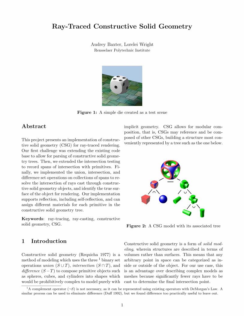
Ray-Traced Constructive Solid Geometry
Audrey Baxter, Lorelei WrightRensselaer Polytechnic Institute
Figure 1: A simple die created as a test scene
Abstract
This project presents an implementation of construc-tive solid geometry (CSG) for ray-traced rendering.Our first challenge was extending the existing codebase to allow for parsing of constructive solid geome-try trees. Then, we extended the intersection testingto record spans of intersection with primitives. Fi-nally, we implemented the union, intersection, anddifference set operations on collections of spans to re-solve the intersection of rays cast through construc-tive solid geometry objects, and identify the true sur-face of the object for rendering. Our implementationsupports reflection, including self-reflection, and canassign different materials for each primitive in theconstructive solid geometry tree.
Keywords: ray-tracing, ray-casting, constructivesolid geometry, CSG.
1 Introduction
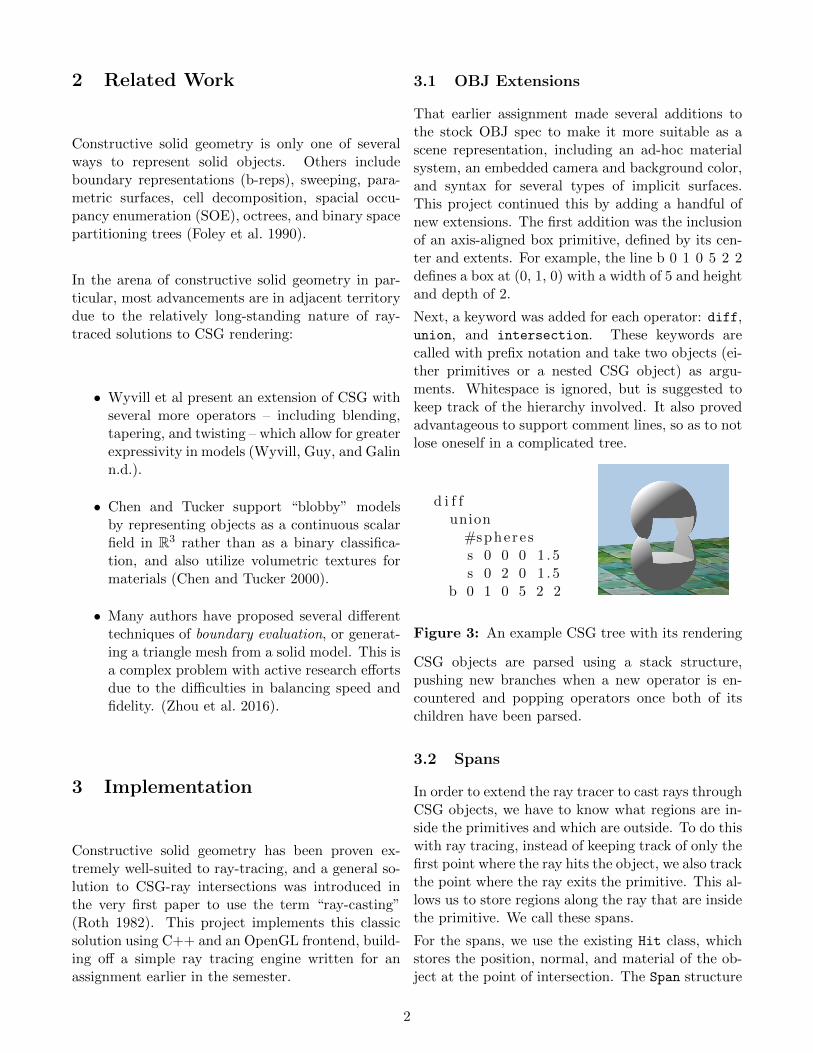
Constructive solid geometry (Requicha 1977) is amethod of modeling which uses the three 1 binary setoperations union (S ∪ T ), intersection (S ∩ T ), anddifference (S−T ) to compose primitive objects suchas spheres, cubes, and cylinders into shapes whichwould be prohibitively complex to model purely with
implicit geometry. CSG allows for modular com-position, that is, CSGs may reference and be com-posed of other CSGs, building a structure most con-veniently represented by a tree such as the one below.
Figure 2: A CSG model with its associated tree
Constructive solid geometry is a form of solid mod-eling, wherein structures are described in terms ofvolumes rather than surfaces. This means that anyarbitrary point in space can be categorized as in-side or outside of the object. For our use case, thisis an advantage over describing complex models asmeshes because significantly fewer rays have to becast to determine the final intersection point.
1A complement operator (¬S) is not necessary, as it can be represented using existing operators with DeMorgan’s Law. Asimilar process can be used to eliminate difference (Duff 1992), but we found difference too practically useful to leave out.
1
2 Related Work
Constructive solid geometry is only one of severalways to represent solid objects. Others includeboundary representations (b-reps), sweeping, para-metric surfaces, cell decomposition, spacial occu-pancy enumeration (SOE), octrees, and binary spacepartitioning trees (Foley et al. 1990).
In the arena of constructive solid geometry in par-ticular, most advancements are in adjacent territorydue to the relatively long-standing nature of ray-traced solutions to CSG rendering:
• Wyvill et al present an extension of CSG withseveral more operators – including blending,tapering, and twisting – which allow for greaterexpressivity in models (Wyvill, Guy, and Galinn.d.).
• Chen and Tucker support “blobby” modelsby representing objects as a continuous scalarfield in R3 rather than as a binary classifica-tion, and also utilize volumetric textures formaterials (Chen and Tucker 2000).
• Many authors have proposed several differenttechniques of boundary evaluation, or generat-ing a triangle mesh from a solid model. This isa complex problem with active research effortsdue to the difficulties in balancing speed andfidelity. (Zhou et al. 2016).
3 Implementation
Constructive solid geometry has been proven ex-tremely well-suited to ray-tracing, and a general so-lution to CSG-ray intersections was introduced inthe very first paper to use the term “ray-casting”(Roth 1982). This project implements this classicsolution using C++ and an OpenGL frontend, build-ing off a simple ray tracing engine written for anassignment earlier in the semester.
3.1 OBJ Extensions
That earlier assignment made several additions tothe stock OBJ spec to make it more suitable as ascene representation, including an ad-hoc materialsystem, an embedded camera and background color,and syntax for several types of implicit surfaces.This project continued this by adding a handful ofnew extensions. The first addition was the inclusionof an axis-aligned box primitive, defined by its cen-ter and extents. For example, the line b 0 1 0 5 2 2defines a box at (0, 1, 0) with a width of 5 and heightand depth of 2.
Next, a keyword was added for each operator: diff,union, and intersection. These keywords arecalled with prefix notation and take two objects (ei-ther primitives or a nested CSG object) as argu-ments. Whitespace is ignored, but is suggested tokeep track of the hierarchy involved. It also provedadvantageous to support comment lines, so as to notlose oneself in a complicated tree.
d i f funion
#sphere ss 0 0 0 1 .5s 0 2 0 1 .5
b 0 1 0 5 2 2
Figure 3: An example CSG tree with its rendering
CSG objects are parsed using a stack structure,pushing new branches when a new operator is en-countered and popping operators once both of itschildren have been parsed.
3.2 Spans
In order to extend the ray tracer to cast rays throughCSG objects, we have to know what regions are in-side the primitives and which are outside. To do thiswith ray tracing, instead of keeping track of only thefirst point where the ray hits the object, we also trackthe point where the ray exits the primitive. This al-lows us to store regions along the ray that are insidethe primitive. We call these spans.
For the spans, we use the existing Hit class, whichstores the position, normal, and material of the ob-ject at the point of intersection. The Span structure
2
is a POD (plain old data type), simply storing oneHit for when the ray enters the volume, and anotherwhen it exits. This gives us not only the segment ofthe ray inside the volume, but also the surface in-formation (normal and material) at the intersectionpoint. This will be important later on when handlingthe application of the set operations on collectionsof sets.
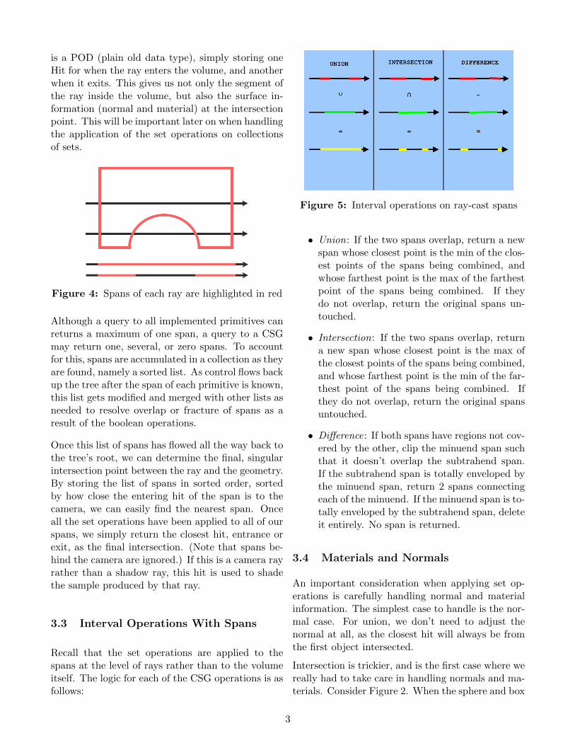
Figure 4: Spans of each ray are highlighted in red
Although a query to all implemented primitives canreturns a maximum of one span, a query to a CSGmay return one, several, or zero spans. To accountfor this, spans are accumulated in a collection as theyare found, namely a sorted list. As control flows backup the tree after the span of each primitive is known,this list gets modified and merged with other lists asneeded to resolve overlap or fracture of spans as aresult of the boolean operations.
Once this list of spans has flowed all the way back tothe tree’s root, we can determine the final, singularintersection point between the ray and the geometry.By storing the list of spans in sorted order, sortedby how close the entering hit of the span is to thecamera, we can easily find the nearest span. Onceall the set operations have been applied to all of ourspans, we simply return the closest hit, entrance orexit, as the final intersection. (Note that spans be-hind the camera are ignored.) If this is a camera rayrather than a shadow ray, this hit is used to shadethe sample produced by that ray.
3.3 Interval Operations With Spans
Recall that the set operations are applied to thespans at the level of rays rather than to the volumeitself. The logic for each of the CSG operations is asfollows:
Figure 5: Interval operations on ray-cast spans
• Union: If the two spans overlap, return a newspan whose closest point is the min of the clos-est points of the spans being combined, andwhose farthest point is the max of the farthestpoint of the spans being combined. If theydo not overlap, return the original spans un-touched.
• Intersection: If the two spans overlap, returna new span whose closest point is the max ofthe closest points of the spans being combined,and whose farthest point is the min of the far-thest point of the spans being combined. Ifthey do not overlap, return the original spansuntouched.
• Difference: If both spans have regions not cov-ered by the other, clip the minuend span suchthat it doesn’t overlap the subtrahend span.If the subtrahend span is totally enveloped bythe minuend span, return 2 spans connectingeach of the minuend. If the minuend span is to-tally enveloped by the subtrahend span, deleteit entirely. No span is returned.
3.4 Materials and Normals
An important consideration when applying set op-erations is carefully handling normal and materialinformation. The simplest case to handle is the nor-mal case. For union, we don’t need to adjust thenormal at all, as the closest hit will always be fromthe first object intersected.
Intersection is trickier, and is the first case where wereally had to take care in handling normals and ma-terials. Consider Figure 2. When the sphere and box
3
are intersected on the left side of the tree, the curvyparts of the new rounded box should be blue like thesphere, and the flat parts should be red like the box.To do this, returning the max hit as described willdo the trick, as the hits contain material informa-tion, and the maximum distance hit will contain thematerial information for that primitive.
Difference again is another important place to beweary. In Figure 2 again, on the difference operation,we see that the green of the cylinders is “pasted”onto the inside of the geometry. So, instead of sim-ply clipping the span for the minuend object, we re-place one of the minuend span’s hits with whicheverhit in the subtrahend span lies at the newly-createdboundary. However, the hit cannot be slotted intothe new span unchanged. Leaving it untouched leadsto artifacts where the normal are flipped. To com-bat this, whenever we do this kind of “pasting” logic,we negate the normal of the hit from the subtractedgeometry, ensuring our normal stays geometricallyvalid.
4 Results
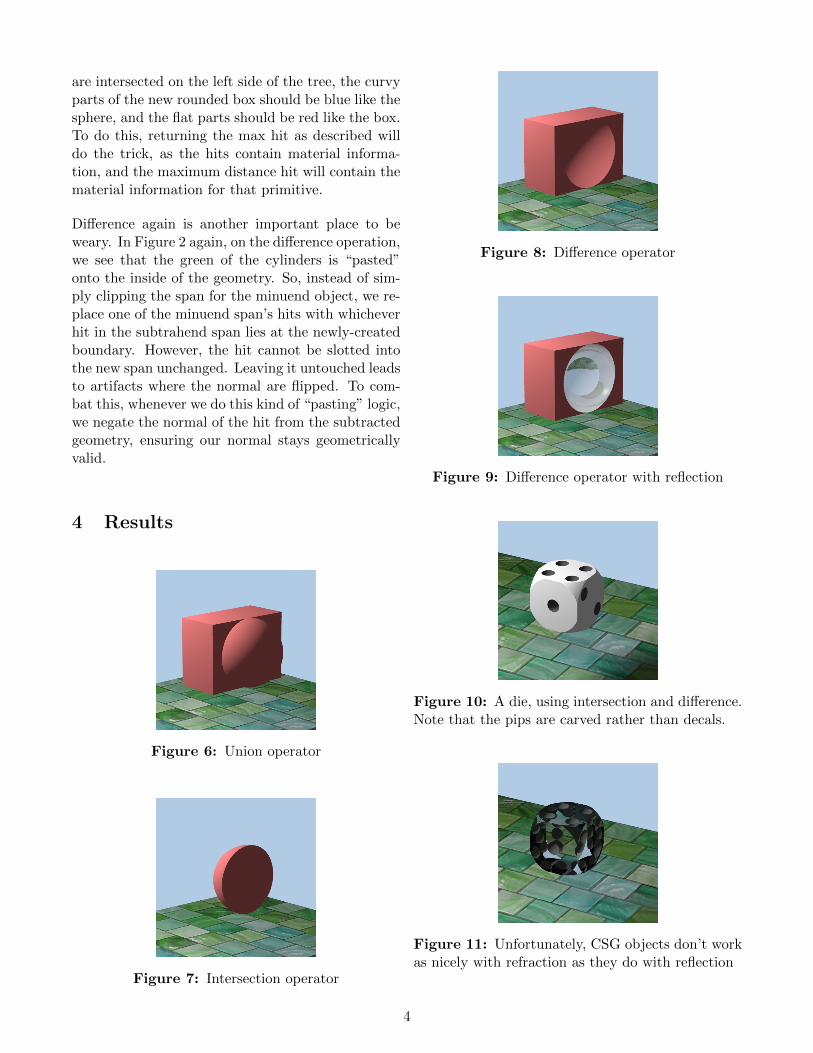
Figure 6: Union operator
Figure 7: Intersection operator
Figure 8: Difference operator
Figure 9: Difference operator with reflection
Figure 10: A die, using intersection and difference.Note that the pips are carved rather than decals.
Figure 11: Unfortunately, CSG objects don’t workas nicely with refraction as they do with reflection
4
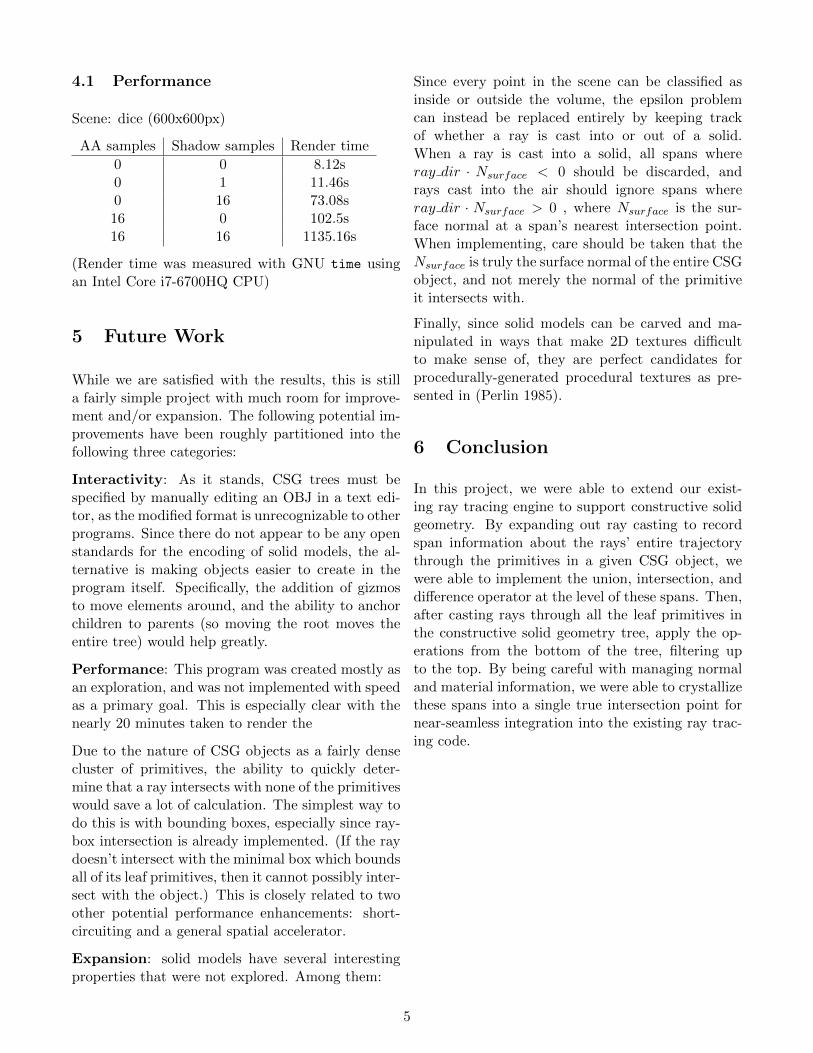
4.1 Performance
Scene: dice (600x600px)
AA samples Shadow samples Render time
0 0 8.12s0 1 11.46s0 16 73.08s16 0 102.5s16 16 1135.16s
(Render time was measured with GNU time usingan Intel Core i7-6700HQ CPU)
5 Future Work
While we are satisfied with the results, this is stilla fairly simple project with much room for improve-ment and/or expansion. The following potential im-provements have been roughly partitioned into thefollowing three categories:
Interactivity: As it stands, CSG trees must bespecified by manually editing an OBJ in a text edi-tor, as the modified format is unrecognizable to otherprograms. Since there do not appear to be any openstandards for the encoding of solid models, the al-ternative is making objects easier to create in theprogram itself. Specifically, the addition of gizmosto move elements around, and the ability to anchorchildren to parents (so moving the root moves theentire tree) would help greatly.
Performance: This program was created mostly asan exploration, and was not implemented with speedas a primary goal. This is especially clear with thenearly 20 minutes taken to render the
Due to the nature of CSG objects as a fairly densecluster of primitives, the ability to quickly deter-mine that a ray intersects with none of the primitiveswould save a lot of calculation. The simplest way todo this is with bounding boxes, especially since ray-box intersection is already implemented. (If the raydoesn’t intersect with the minimal box which boundsall of its leaf primitives, then it cannot possibly inter-sect with the object.) This is closely related to twoother potential performance enhancements: short-circuiting and a general spatial accelerator.
Expansion: solid models have several interestingproperties that were not explored. Among them:
Since every point in the scene can be classified asinside or outside the volume, the epsilon problemcan instead be replaced entirely by keeping trackof whether a ray is cast into or out of a solid.When a ray is cast into a solid, all spans whereray dir · Nsurface < 0 should be discarded, andrays cast into the air should ignore spans whereray dir · Nsurface > 0 , where Nsurface is the sur-face normal at a span’s nearest intersection point.When implementing, care should be taken that theNsurface is truly the surface normal of the entire CSGobject, and not merely the normal of the primitiveit intersects with.
Finally, since solid models can be carved and ma-nipulated in ways that make 2D textures difficultto make sense of, they are perfect candidates forprocedurally-generated procedural textures as pre-sented in (Perlin 1985).
6 Conclusion
In this project, we were able to extend our exist-ing ray tracing engine to support constructive solidgeometry. By expanding out ray casting to recordspan information about the rays’ entire trajectorythrough the primitives in a given CSG object, wewere able to implement the union, intersection, anddifference operator at the level of these spans. Then,after casting rays through all the leaf primitives inthe constructive solid geometry tree, apply the op-erations from the bottom of the tree, filtering upto the top. By being careful with managing normaland material information, we were able to crystallizethese spans into a single true intersection point fornear-seamless integration into the existing ray trac-ing code.
5
References
Chen, M. and J. V. Tucker (2000). “Constructive Volume Geometry.” In: Computer Graphics Forum 19.4,pp. 281–293.
Duff, T. (1992). “Interval arithmetic and recursive subdivision for implicit functions and constructive solidgeometry.” In: ACM/SIGGRAPH Computer Graphics 26.2, pp. 131–138.
Foley, J. D. et al. (1990). Computer Graphics: Principles and Practice. Addison-Wesley.Perlin, Ken (July 1985). “An Image Synthesizer.” In: SIGGRAPH Comput. Graph. 19.3, pp. 287–296. issn:
0097-8930. doi: 10.1145/325165.325247. url: http://doi.acm.org/10.1145/325165.325247.Requicha, A. A. G. (1977). Mathematical Models of Rigid Solids. Technical Memo 28. Production Automa-
tion Project, University of Rochester.Roth, S. D. (1982). “Ray casting for modeling solids.” In: Computer Graphics and Image Processing 18.2,
pp. 109–144.Wyvill, B., A. Guy, and E. Galin (n.d.). “Extending the CSG tree: warping, blending, and Boolean oper-
ations in an implicit surface modeling system.” In: Computer Graphics Forum 18.2 (), pp. 149–158.Zhou, Qingnan et al. (2016). “Mesh Arrangements for Solid Geometry.” In: ACM Transactions on Graphics
(TOG) 35.4.
6


![CONSTRUCTIVE VOLUME GEOMETRY · Constructive Solid Geometry [REQU77], have a sound theoretical foundation, and are well supported by commercial modelling tools. However, the primary](https://img.pdfslide.net/doc/110x75/606348c4c1510a2698107791/constructive-volume-geometry-constructive-solid-geometry-requ77-have-a-sound.jpg)