Embed Size (px)
Citation preview

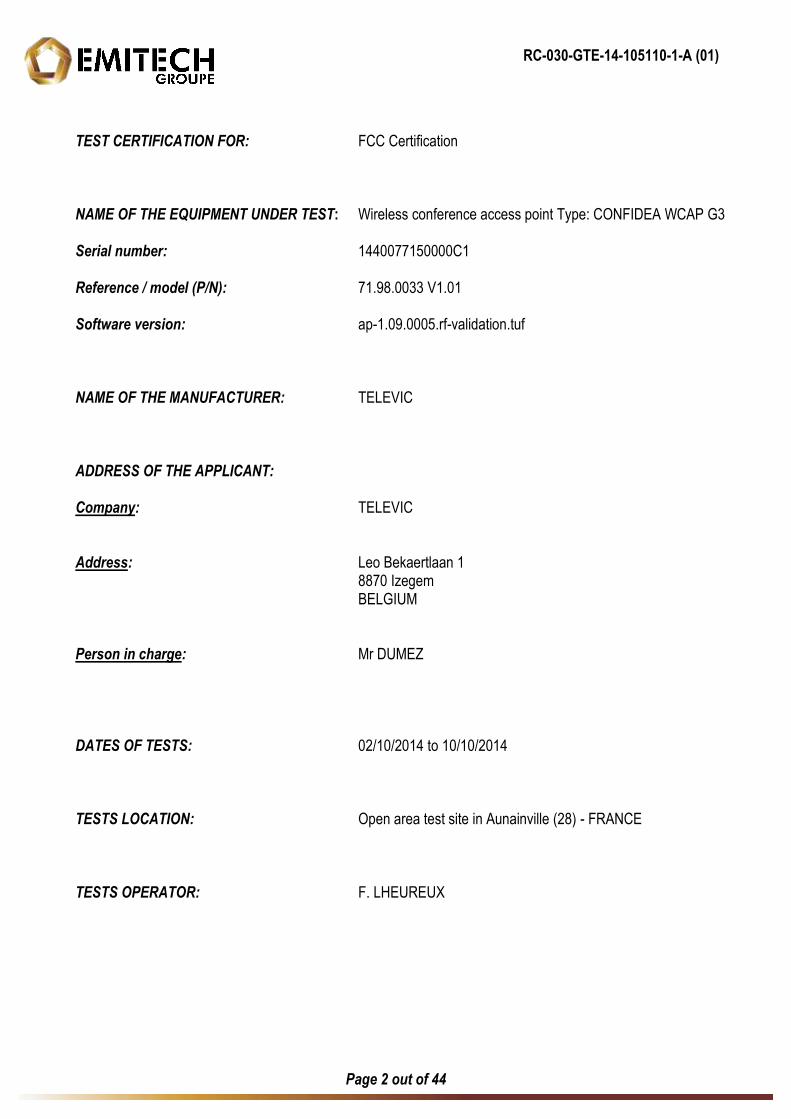
RC-030-GTE-14-105110-1-A (01)
Page 2 out of 44
TEST CERTIFICATION FOR: FCC Certification NAME OF THE EQUIPMENT UNDER TEST: Wireless conference access point Type: CONFIDEA WCAP G3 Serial number: 1440077150000C1 Reference / model (P/N): 71.98.0033 V1.01 Software version: ap-1.09.0005.rf-validation.tuf NAME OF THE MANUFACTURER: TELEVIC ADDRESS OF THE APPLICANT: Company: TELEVIC Address: Leo Bekaertlaan 1 8870 Izegem BELGIUM Person in charge: Mr DUMEZ DATES OF TESTS: 02/10/2014 to 10/10/2014 TESTS LOCATION: Open area test site in Aunainville (28) - FRANCE TESTS OPERATOR: F. LHEUREUX
RC-030-GTE-14-105110-1-A (01)
Page 3 out of 44
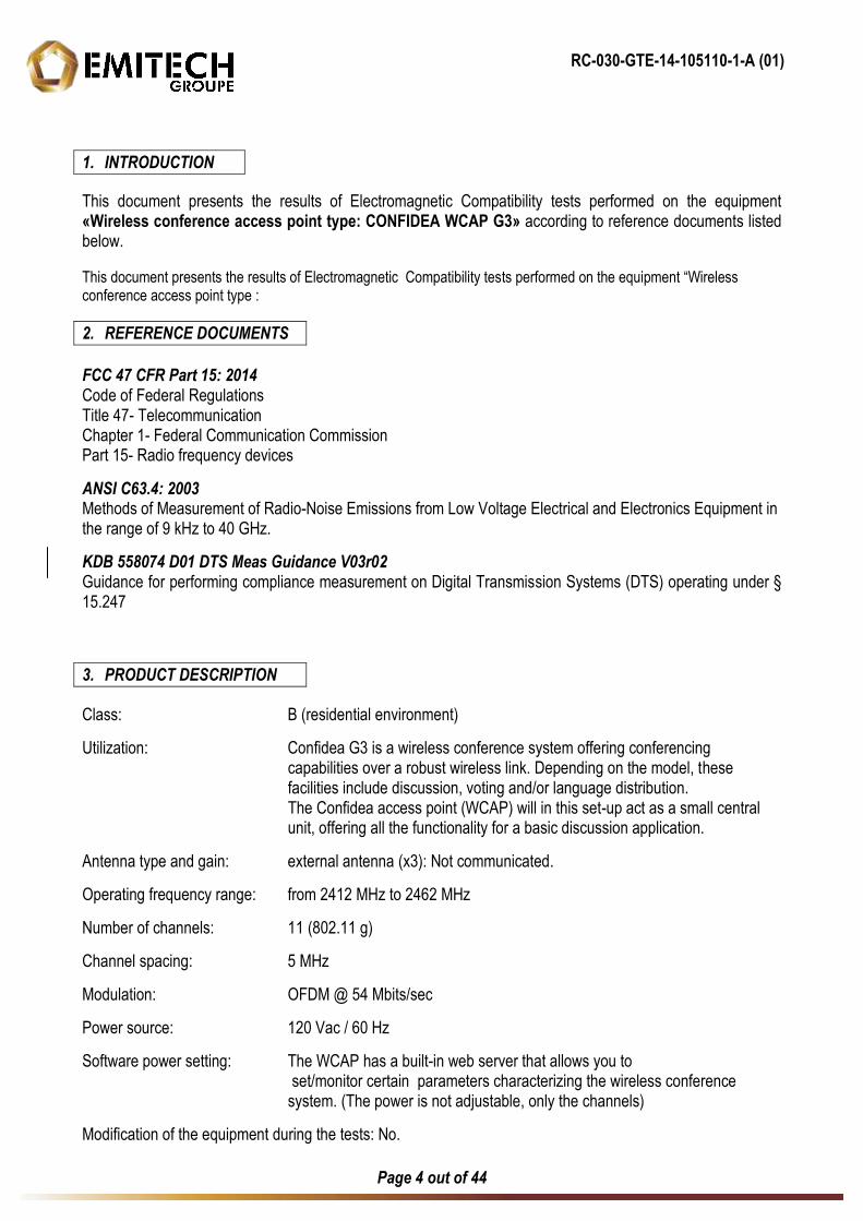
TABLE OF CONTENTS
1. INTRODUCTION ____________________________________________________________________ 4
2. REFERENCE DOCUMENTS ___________________________________________________________ 4
3. PRODUCT DESCRIPTION ____________________________________________________________ 4
4. TESTS AND CONCLUSION ___________________________________________________________ 5
5. CONDUCTED EMISSION _____________________________________________________________ 7
6. DIGITAL MODULATION SYSTEMS ____________________________________________________ 10
7. TRANSMITTER OUTPUT POWER _____________________________________________________ 12
8. PEAK POWER SPECTRAL DENSITY __________________________________________________ 14
9. ADDITIONAL PROVISIONS TO THE GENERAL RADIATED EMISSIONS LIMITATION ___________ 16
10. UNINTENTIONAL RADIATED EMISSIONS AND TRANSMITTER UNWANTED EMISSION IN THE BAND 9 KHz – 25 GHz______________________________________________________________ 17
ANNEX 1: ANTENNA FACTORS, INSERTION LOSSES AND AMPLIFIER VALUES
ANNEX 2: EXTERNAL PHOTOGRAPHIES
ANNEX 3: TEST SETUP PHOTOGRAPHIES
ANNEX 4: 6 DB BANDWIDTH
ANNEX 5: BAND EDGE
ANNEX 6: CALIBRATION DATES
RC-030-GTE-14-105110-1-A (01)
Page 4 out of 44
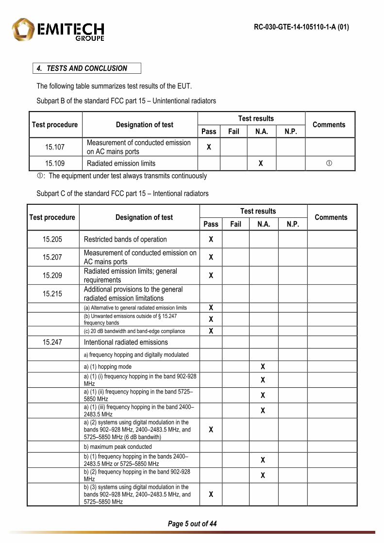
1. INTRODUCTION
This document presents the results of Electromagnetic Compatibility tests performed on the equipment «Wireless conference access point type: CONFIDEA WCAP G3» according to reference documents listed below.
This document presents the results of Electromagnetic Compatibility tests performed on the equipment “Wireless conference access point type :
2. REFERENCE DOCUMENTS
FCC 47 CFR Part 15: 2014 Code of Federal Regulations Title 47- Telecommunication Chapter 1- Federal Communication Commission Part 15- Radio frequency devices
ANSI C63.4: 2003
Methods of Measurement of Radio-Noise Emissions from Low Voltage Electrical and Electronics Equipment in the range of 9 kHz to 40 GHz. KDB 558074 D01 DTS Meas Guidance V03r02 Guidance for performing compliance measurement on Digital Transmission Systems (DTS) operating under § 15.247
3. PRODUCT DESCRIPTION
Class: B (residential environment)
Utilization: Confidea G3 is a wireless conference system offering conferencing capabilities over a robust wireless link. Depending on the model, these facilities include discussion, voting and/or language distribution. The Confidea access point (WCAP) will in this set-up act as a small central unit, offering all the functionality for a basic discussion application.
Antenna type and gain: external antenna (x3): Not communicated.
Operating frequency range: from 2412 MHz to 2462 MHz
Number of channels: 11 (802.11 g)
Channel spacing: 5 MHz
Modulation: OFDM @ 54 Mbits/sec
Power source: 120 Vac / 60 Hz
Software power setting: The WCAP has a built-in web server that allows you to set/monitor certain parameters characterizing the wireless conference system. (The power is not adjustable, only the channels)
Modification of the equipment during the tests: No.
RC-030-GTE-14-105110-1-A (01)
Page 5 out of 44
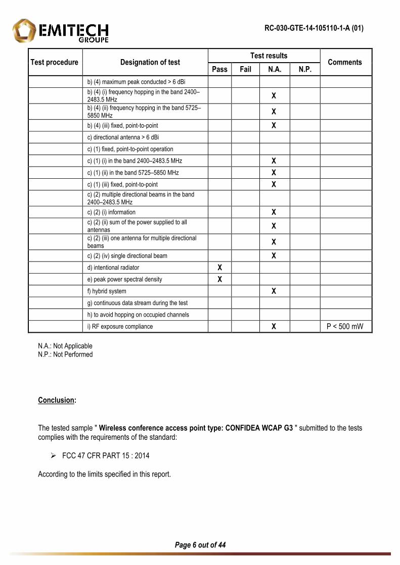
4. TESTS AND CONCLUSION
The following table summarizes test results of the EUT.
Subpart B of the standard FCC part 15 – Unintentional radiators
Test procedure Designation of test Test results
Comments Pass Fail N.A. N.P.
15.107 Measurement of conducted emission on AC mains ports
X
15.109 Radiated emission limits X
: The equipment under test always transmits continuously Subpart C of the standard FCC part 15 – Intentional radiators
Test procedure Designation of test Test results
Comments Pass Fail N.A. N.P.
15.205 Restricted bands of operation X
15.207 Measurement of conducted emission on AC mains ports
X
15.209 Radiated emission limits; general requirements
X
15.215 Additional provisions to the general radiated emission limitations
(a) Alternative to general radiated emission limits X
(b) Unwanted emissions outside of § 15.247 frequency bands
X
(c) 20 dB bandwidth and band-edge compliance X
15.247 Intentional radiated emissions
a) frequency hopping and digitally modulated
a) (1) hopping mode X
a) (1) (i) frequency hopping in the band 902-928 MHz
X
a) (1) (ii) frequency hopping in the band 5725–5850 MHz
X
a) (1) (iii) frequency hopping in the band 2400–2483.5 MHz
X
a) (2) systems using digital modulation in the bands 902–928 MHz, 2400–2483.5 MHz, and 5725–5850 MHz (6 dB bandwith)
X
b) maximum peak conducted
b) (1) frequency hopping in the bands 2400–2483.5 MHz or 5725–5850 MHz
X
b) (2) frequency hopping in the band 902-928 MHz
X
b) (3) systems using digital modulation in the bands 902–928 MHz, 2400–2483.5 MHz, and 5725–5850 MHz
X
RC-030-GTE-14-105110-1-A (01)
Page 6 out of 44
Test procedure Designation of test Test results
Comments Pass Fail N.A. N.P.
b) (4) maximum peak conducted > 6 dBi
b) (4) (i) frequency hopping in the band 2400–2483.5 MHz
X
b) (4) (ii) frequency hopping in the band 5725–5850 MHz
X
b) (4) (iii) fixed, point-to-point X
c) directional antenna > 6 dBi
c) (1) fixed, point-to-point operation
c) (1) (i) in the band 2400–2483.5 MHz X
c) (1) (ii) in the band 5725–5850 MHz X
c) (1) (iii) fixed, point-to-point X
c) (2) multiple directional beams in the band 2400–2483.5 MHz
c) (2) (i) information X
c) (2) (ii) sum of the power supplied to all antennas
X
c) (2) (iii) one antenna for multiple directional beams
X
c) (2) (iv) single directional beam X
d) intentional radiator X
e) peak power spectral density X
f) hybrid system X
g) continuous data stream during the test
h) to avoid hopping on occupied channels
i) RF exposure compliance X P < 500 mW
N.A.: Not Applicable N.P.: Not Performed
Conclusion: The tested sample " Wireless conference access point type: CONFIDEA WCAP G3 " submitted to the tests complies with the requirements of the standard: FCC 47 CFR PART 15 : 2014
According to the limits specified in this report.
RC-030-GTE-14-105110-1-A (01)
Page 7 out of 44
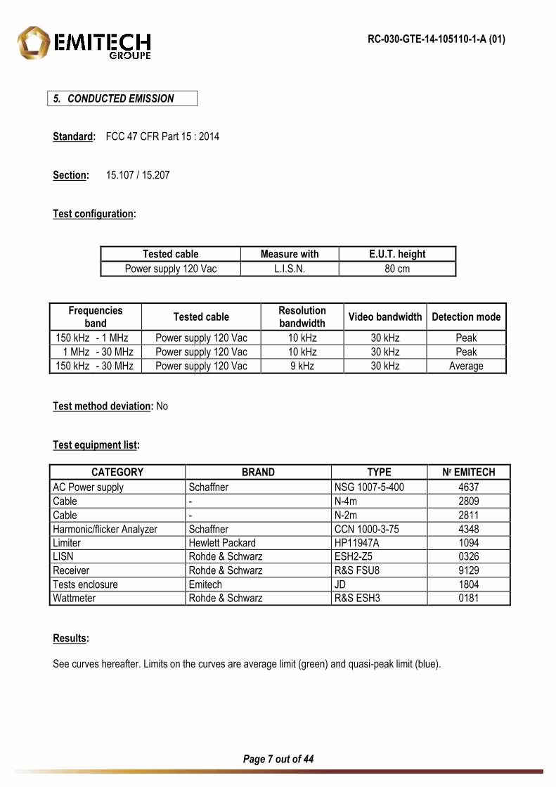
5. CONDUCTED EMISSION
Standard: FCC 47 CFR Part 15 : 2014 Section: 15.107 / 15.207 Test configuration:
Tested cable Measure with E.U.T. height Power supply 120 Vac L.I.S.N. 80 cm
Frequencies band Tested cable Resolution
bandwidth Video bandwidth Detection mode
150 kHz - 1 MHz Power supply 120 Vac 10 kHz 30 kHz Peak
1 MHz - 30 MHz Power supply 120 Vac 10 kHz 30 kHz Peak
150 kHz - 30 MHz Power supply 120 Vac 9 kHz 30 kHz Average
Test method deviation: No Test equipment list:
CATEGORY BRAND TYPE Nr EMITECH AC Power supply Schaffner NSG 1007-5-400 4637
Cable - N-4m 2809
Cable - N-2m 2811
Harmonic/flicker Analyzer Schaffner CCN 1000-3-75 4348
Limiter Hewlett Packard HP11947A 1094
LISN Rohde & Schwarz ESH2-Z5 0326
Receiver Rohde & Schwarz R&S FSU8 9129
Tests enclosure Emitech JD 1804
Wattmeter Rohde & Schwarz R&S ESH3 0181
Results: See curves hereafter. Limits on the curves are average limit (green) and quasi-peak limit (blue).
RC-030-GTE-14-105110-1-A (01)
Page 8 out of 44
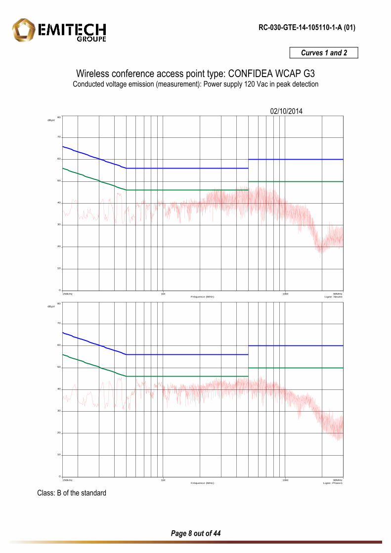
Curves 1 and 2
Wireless conference access point type: CONFIDEA WCAP G3 Conducted voltage emission (measurement): Power supply 120 Vac in peak detection
02/10/2014
150kHz 30MHz1M 10M
Fréquence (MHz) Ligne: Neutre
0
80
dBµV
70
60
50
40
30
20
10
150kHz 30MHz1M 10M
Fréquence (MHz) Ligne: Phase1
0
80
dBµV
70
60
50
40
30
20
10
Class: B of the standard
RC-030-GTE-14-105110-1-A (01)
Page 9 out of 44
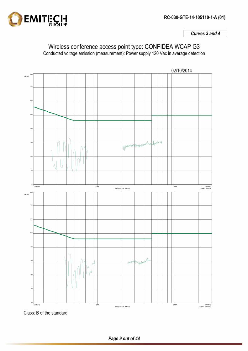
Curves 3 and 4
Wireless conference access point type: CONFIDEA WCAP G3 Conducted voltage emission (measurement): Power supply 120 Vac in average detection
02/10/2014
150kHz 30MHz1M 10M
Fréquence (MHz) Ligne: Neutre
0
80
dBµV
70
60
50
40
30
20
10
150kHz 30MHz1M 10M
Fréquence (MHz) Ligne: Phase1
0
80
dBµV
70
60
50
40
30
20
10
Class: B of the standard

RC-030-GTE-14-105110-1-A (01)
Page 10 out of 44
6. DIGITAL MODULATION SYSTEMS
Standard: FCC 47 CFR PART 15 : 2014 Section: 15.247 a) (2) Test configuration: The system is tested in an open area test site (OATS). The test unit is placed on a rotating table, 0.8 m from a ground plane. Zero degree azimuth corresponds to the front of the equipment under test. The level was maximised in antenna height, azimuth and polarization. The maximum level measured on the spectrum analyser was recorded. Distance of antenna: 3 meters Instrumentation test list:
CATEGORY BRAND TYPE Nr EMITECH Antenna Emco Cornet 3115 3374
Antenna mast Maturo AM 4.0-O 7625
Cable Micro-Coax N-13m 8063
Open area test site Emitech Aunainville 0187
Power supply AC SECAS CF1000 50/60 2102
Receiver Rohde & Schwarz R&S FSU8 9129
Turntable Maturo MCU 7626
Equipment under test operating condition: EUT is in continuous transmission mode. Measure conditions: Ambient temperature (°C): 15 Relative humidity (%): 69 Resolution bandwidth: 100 kHz
RC-030-GTE-14-105110-1-A (01)
Page 11 out of 44
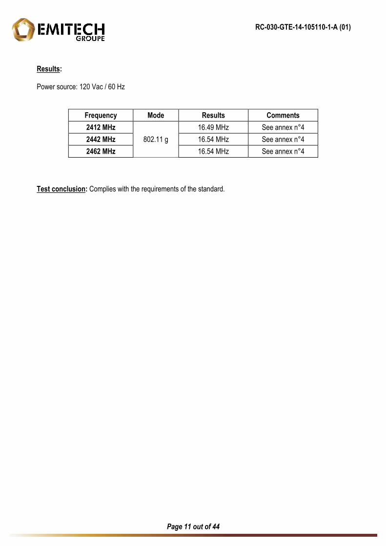
Results: Power source: 120 Vac / 60 Hz
Frequency Mode Results Comments 2412 MHz
802.11 g
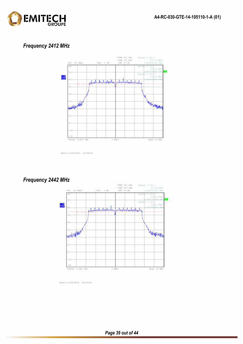
16.49 MHz See annex n°4
2442 MHz 16.54 MHz See annex n°4
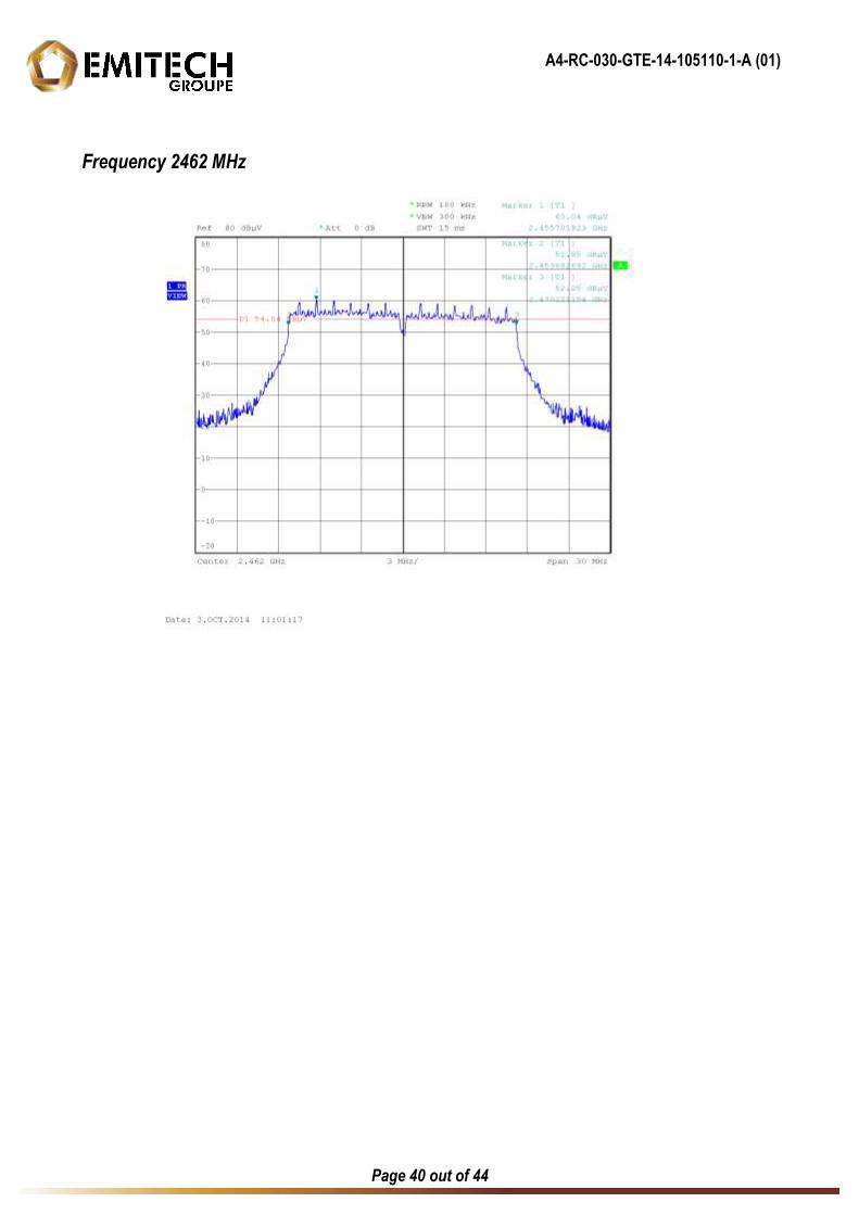
2462 MHz 16.54 MHz See annex n°4
Test conclusion: Complies with the requirements of the standard.
RC-030-GTE-14-105110-1-A (01)
Page 12 out of 44
7. TRANSMITTER OUTPUT POWER
Standard: FCC 47 CFR PART 15 : 2014 Section: 15.247 b) (3) Test configuration: The system is tested in an open area test site (OATS). The test unit is placed on a rotating table, 0.8 m from a ground plane. Zero degree azimuth corresponds to the front of the equipment under test. The level was maximised in antenna height, azimuth and polarization. The maximum level measured on the spectrum analyser was recorded. Distance of antenna: 3 meters Instrumentation test list:
CATEGORY BRAND TYPE Nr EMITECH Antenna Emco Cornet 3115 3374
Antenna mast Maturo AM 4.0-O 7625
Cable Micro-Coax N-13m 8063
Open area test site Emitech Aunainville 0187
Power supply AC SECAS CF1000 50/60 2102
Receiver Rohde & Schwarz R&S FSU8 9129
Turntable Maturo MCU 7626
Equipment under test operating condition: EUT is in continuous transmission mode. Measure conditions: Ambient temperature (°C): 15 Relative humidity (%): 69 Resolution bandwidth: 50 MHz
RC-030-GTE-14-105110-1-A (01)
Page 13 out of 44
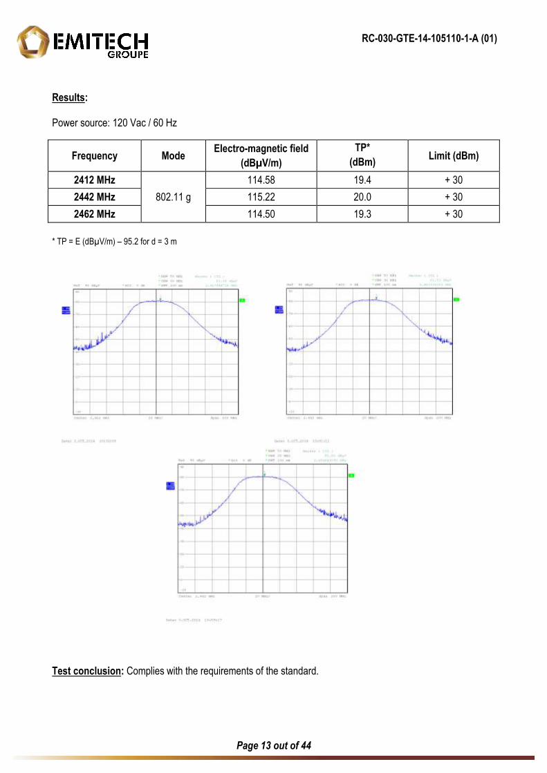
Results: Power source: 120 Vac / 60 Hz
Frequency Mode Electro-magnetic field (dBµV/m)
TP* (dBm) Limit (dBm)
2412 MHz 802.11 g
114.58 19.4 + 30
2442 MHz 115.22 20.0 + 30
2462 MHz 114.50 19.3 + 30
* TP = E (dBµV/m) – 95.2 for d = 3 m
Test conclusion: Complies with the requirements of the standard.
RC-030-GTE-14-105110-1-A (01)
Page 14 out of 44
8. PEAK POWER SPECTRAL DENSITY
Standard: FCC 47 CFR PART 15 : 2014 Section: 15.247 e) Test configuration: The system is tested in an open area test site (OATS). The test unit is placed on a rotating table, 0.8 m from a ground plane. Zero degree azimuth corresponds to the front of the equipment under test. The level was maximised in antenna height, azimuth and polarization. The maximum level measured on the spectrum analyser was recorded. Distance of antenna: 3 meters Instrumentation test list:
CATEGORY BRAND TYPE Nr EMITECH Antenna Emco Cornet 3115 3374
Antenna mast Maturo AM 4.0-O 7625
Cable Micro-Coax N-13m 8063
Open area test site Emitech Aunainville 0187
Power supply AC SECAS CF1000 50/60 2102
Receiver Rohde & Schwarz R&S FSU8 9129
Turntable Maturo MCU 7626
Equipment under test operating condition: EUT is in continuous transmission mode. Measure conditions: Ambient temperature (°C): 15 Relative humidity (%): 69 Resolution bandwidth: 3 kHz Video bandwidth: 3 kHz
RC-030-GTE-14-105110-1-A (01)
Page 15 out of 44
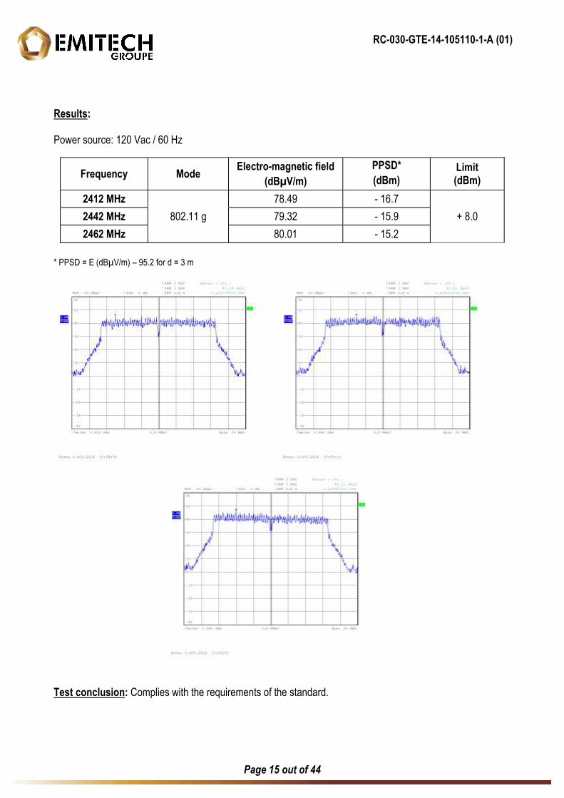
Results: Power source: 120 Vac / 60 Hz
Frequency Mode Electro-magnetic field (dBµV/m)
PPSD* (dBm)
Limit (dBm)
2412 MHz 802.11 g
78.49 - 16.7
+ 8.0 2442 MHz 79.32 - 15.9
2462 MHz 80.01 - 15.2
* PPSD = E (dBµV/m) – 95.2 for d = 3 m
Test conclusion: Complies with the requirements of the standard.
RC-030-GTE-14-105110-1-A (01)
Page 16 out of 44
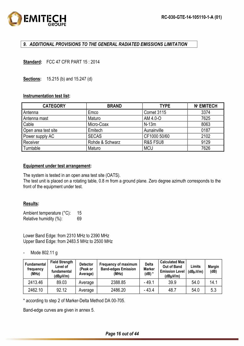
9. ADDITIONAL PROVISIONS TO THE GENERAL RADIATED EMISSIONS LIMITATION
Standard: FCC 47 CFR PART 15 : 2014 Sections: 15.215 (b) and 15.247 (d) Instrumentation test list:
CATEGORY BRAND TYPE Nr EMITECH Antenna Emco Cornet 3115 3374
Antenna mast Maturo AM 4.0-O 7625
Cable Micro-Coax N-13m 8063
Open area test site Emitech Aunainville 0187
Power supply AC SECAS CF1000 50/60 2102
Receiver Rohde & Schwarz R&S FSU8 9129
Turntable Maturo MCU 7626
Equipment under test arrangement:
The system is tested in an open area test site (OATS). The test unit is placed on a rotating table, 0.8 m from a ground plane. Zero degree azimuth corresponds to the front of the equipment under test. Results:
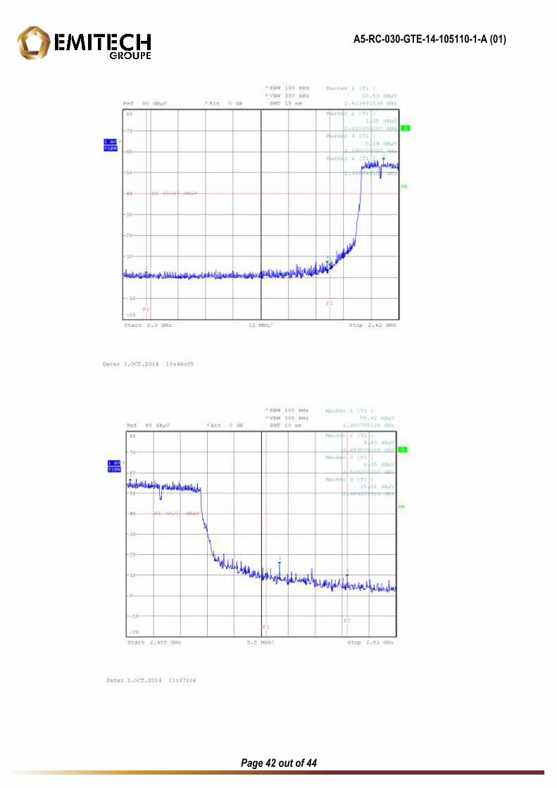
Ambient temperature (°C): 15 Relative humidity (%): 69 Lower Band Edge: from 2310 MHz to 2390 MHz Upper Band Edge: from 2483.5 MHz to 2500 MHz - Mode 802.11 g
Fundamental frequency
(MHz)
Field Strength Level of
fundamental (dBµV/m)
Detector (Peak or Average)
Frequency of maximum Band-edges Emission
(MHz)
Delta Marker (dB) *
Calculated Max Out of Band
Emission Level (dBµV/m)
Limits (dBV/m)
Margin (dB)
2413.46 89.03 Average 2388.85 - 49.1 39.9 54.0 14.1
2462.10 92.12 Average 2486.20 - 43.4 48.7 54.0 5.3
* according to step 2 of Marker-Delta Method DA 00-705.
Band-edge curves are given in annex 5.
RC-030-GTE-14-105110-1-A (01)
Page 17 out of 44
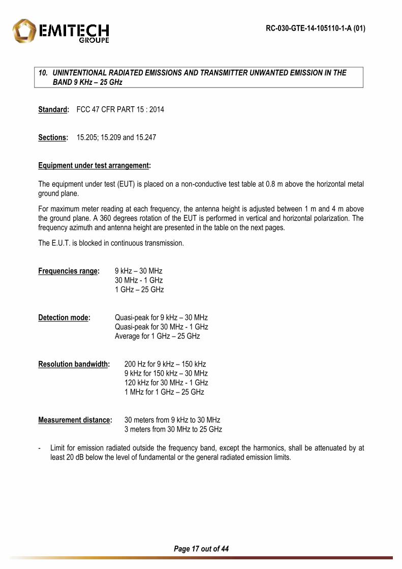
10. UNINTENTIONAL RADIATED EMISSIONS AND TRANSMITTER UNWANTED EMISSION IN THE BAND 9 KHz – 25 GHz
Standard: FCC 47 CFR PART 15 : 2014 Sections: 15.205; 15.209 and 15.247 Equipment under test arrangement: The equipment under test (EUT) is placed on a non-conductive test table at 0.8 m above the horizontal metal ground plane.
For maximum meter reading at each frequency, the antenna height is adjusted between 1 m and 4 m above the ground plane. A 360 degrees rotation of the EUT is performed in vertical and horizontal polarization. The frequency azimuth and antenna height are presented in the table on the next pages.
The E.U.T. is blocked in continuous transmission. Frequencies range: 9 kHz – 30 MHz 30 MHz - 1 GHz
1 GHz – 25 GHz Detection mode: Quasi-peak for 9 kHz – 30 MHz Quasi-peak for 30 MHz - 1 GHz
Average for 1 GHz – 25 GHz Resolution bandwidth: 200 Hz for 9 kHz – 150 kHz 9 kHz for 150 kHz – 30 MHz 120 kHz for 30 MHz - 1 GHz
1 MHz for 1 GHz – 25 GHz Measurement distance: 30 meters from 9 kHz to 30 MHz 3 meters from 30 MHz to 25 GHz - Limit for emission radiated outside the frequency band, except the harmonics, shall be attenuated by at
least 20 dB below the level of fundamental or the general radiated emission limits.
RC-030-GTE-14-105110-1-A (01)
Page 18 out of 44
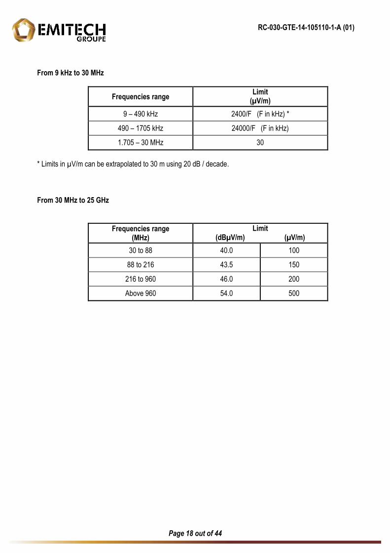
From 9 kHz to 30 MHz
Frequencies range Limit (µV/m)
9 – 490 kHz 2400/F (F in kHz) *
490 – 1705 kHz 24000/F (F in kHz)
1.705 – 30 MHz 30
* Limits in µV/m can be extrapolated to 30 m using 20 dB / decade. From 30 MHz to 25 GHz
Frequencies range (MHz)
Limit (dBµV/m) (µV/m)
30 to 88 40.0 100
88 to 216 43.5 150
216 to 960 46.0 200
Above 960 54.0 500
RC-030-GTE-14-105110-1-A (01)
Page 19 out of 44
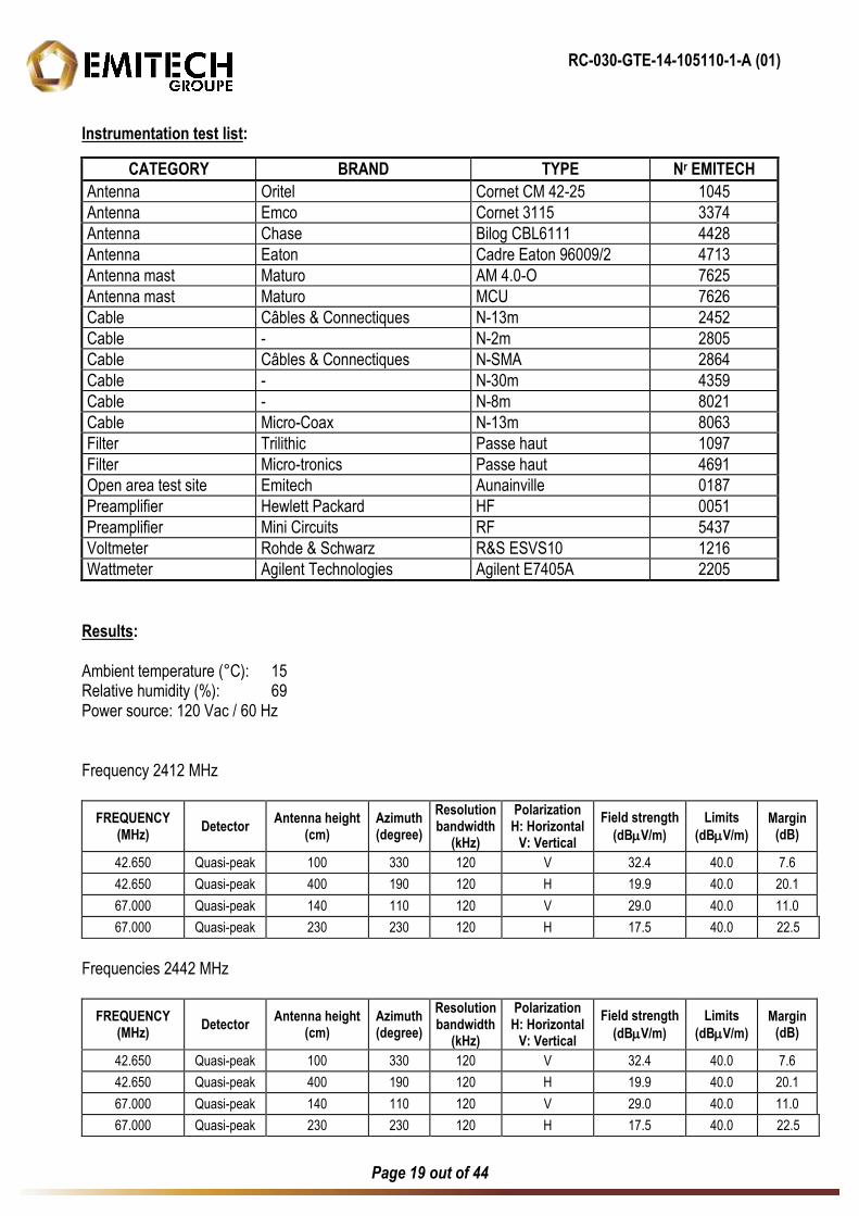
Instrumentation test list:
CATEGORY BRAND TYPE Nr EMITECH Antenna Oritel Cornet CM 42-25 1045
Antenna Emco Cornet 3115 3374
Antenna Chase Bilog CBL6111 4428
Antenna Eaton Cadre Eaton 96009/2 4713
Antenna mast Maturo AM 4.0-O 7625
Antenna mast Maturo MCU 7626
Cable Câbles & Connectiques N-13m 2452
Cable - N-2m 2805
Cable Câbles & Connectiques N-SMA 2864
Cable - N-30m 4359
Cable - N-8m 8021
Cable Micro-Coax N-13m 8063
Filter Trilithic Passe haut 1097
Filter Micro-tronics Passe haut 4691
Open area test site Emitech Aunainville 0187
Preamplifier Hewlett Packard HF 0051
Preamplifier Mini Circuits RF 5437
Voltmeter Rohde & Schwarz R&S ESVS10 1216
Wattmeter Agilent Technologies Agilent E7405A 2205
Results: Ambient temperature (°C): 15 Relative humidity (%): 69 Power source: 120 Vac / 60 Hz Frequency 2412 MHz
FREQUENCY (MHz) Detector Antenna height
(cm) Azimuth (degree)
Resolution bandwidth
(kHz)
Polarization H: Horizontal
V: Vertical Field strength
(dBV/m) Limits
(dBV/m) Margin
(dB)
42.650 Quasi-peak 100 330 120 V 32.4 40.0 7.6
42.650 Quasi-peak 400 190 120 H 19.9 40.0 20.1
67.000 Quasi-peak 140 110 120 V 29.0 40.0 11.0
67.000 Quasi-peak 230 230 120 H 17.5 40.0 22.5
Frequencies 2442 MHz
FREQUENCY (MHz) Detector Antenna height
(cm) Azimuth (degree)
Resolution bandwidth
(kHz)
Polarization H: Horizontal
V: Vertical Field strength
(dBV/m) Limits
(dBV/m) Margin
(dB)
42.650 Quasi-peak 100 330 120 V 32.4 40.0 7.6
42.650 Quasi-peak 400 190 120 H 19.9 40.0 20.1
67.000 Quasi-peak 140 110 120 V 29.0 40.0 11.0
67.000 Quasi-peak 230 230 120 H 17.5 40.0 22.5
RC-030-GTE-14-105110-1-A (01)
Page 20 out of 44
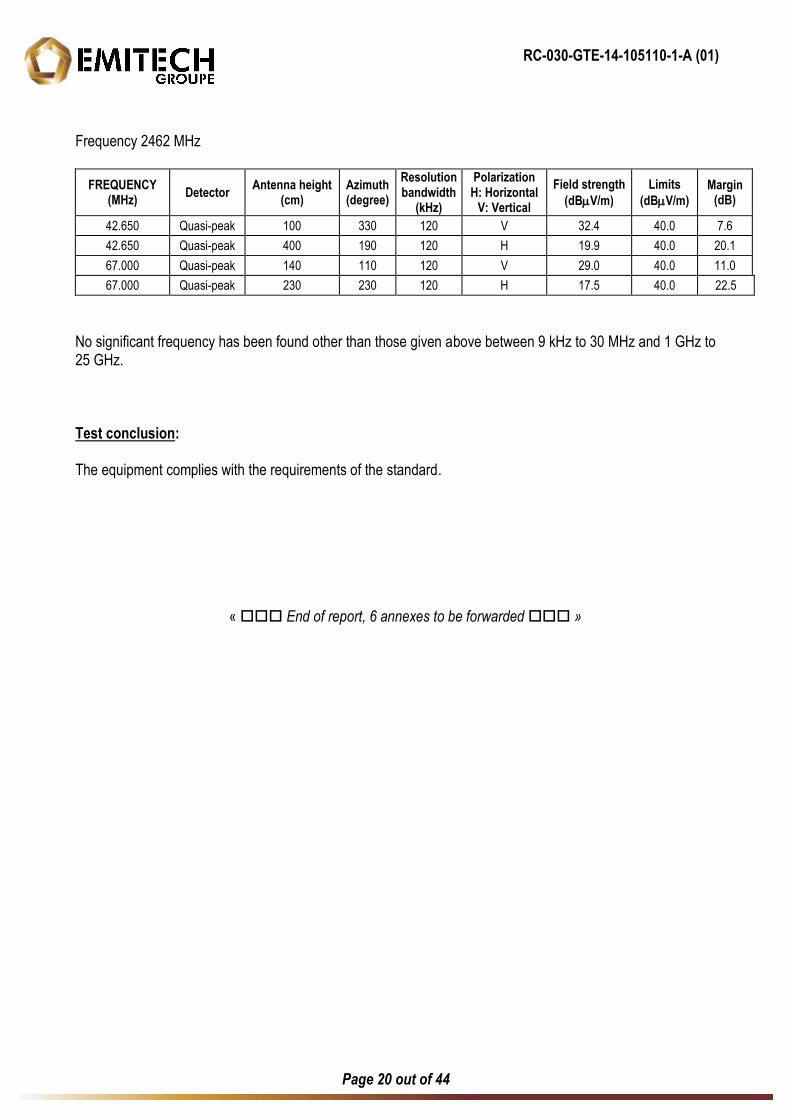
Frequency 2462 MHz
FREQUENCY (MHz) Detector Antenna height
(cm) Azimuth (degree)
Resolution bandwidth
(kHz)
Polarization H: Horizontal
V: Vertical Field strength
(dBV/m) Limits
(dBV/m) Margin
(dB)
42.650 Quasi-peak 100 330 120 V 32.4 40.0 7.6
42.650 Quasi-peak 400 190 120 H 19.9 40.0 20.1
67.000 Quasi-peak 140 110 120 V 29.0 40.0 11.0
67.000 Quasi-peak 230 230 120 H 17.5 40.0 22.5
No significant frequency has been found other than those given above between 9 kHz to 30 MHz and 1 GHz to 25 GHz. Test conclusion: The equipment complies with the requirements of the standard.
« End of report, 6 annexes to be forwarded »
A1-RC-030-GTE-14-105110-1-A (01)
Page 21 out of 44
ANNEX 1
ANTENNA FACTORS, INSERTION LOSSES AND AMPLIFIER VALUES
A1-RC-030-GTE-14-105110-1-A (01)
Page 22 out of 44
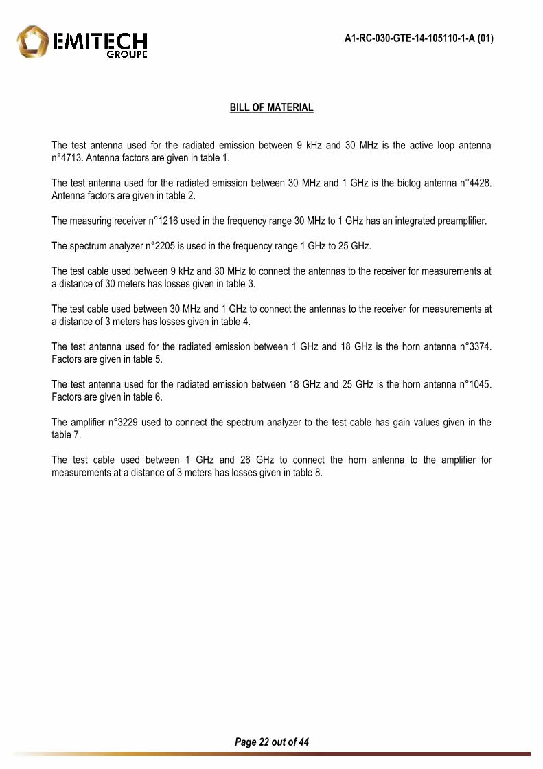
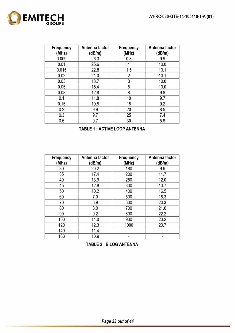
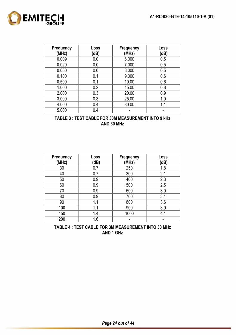
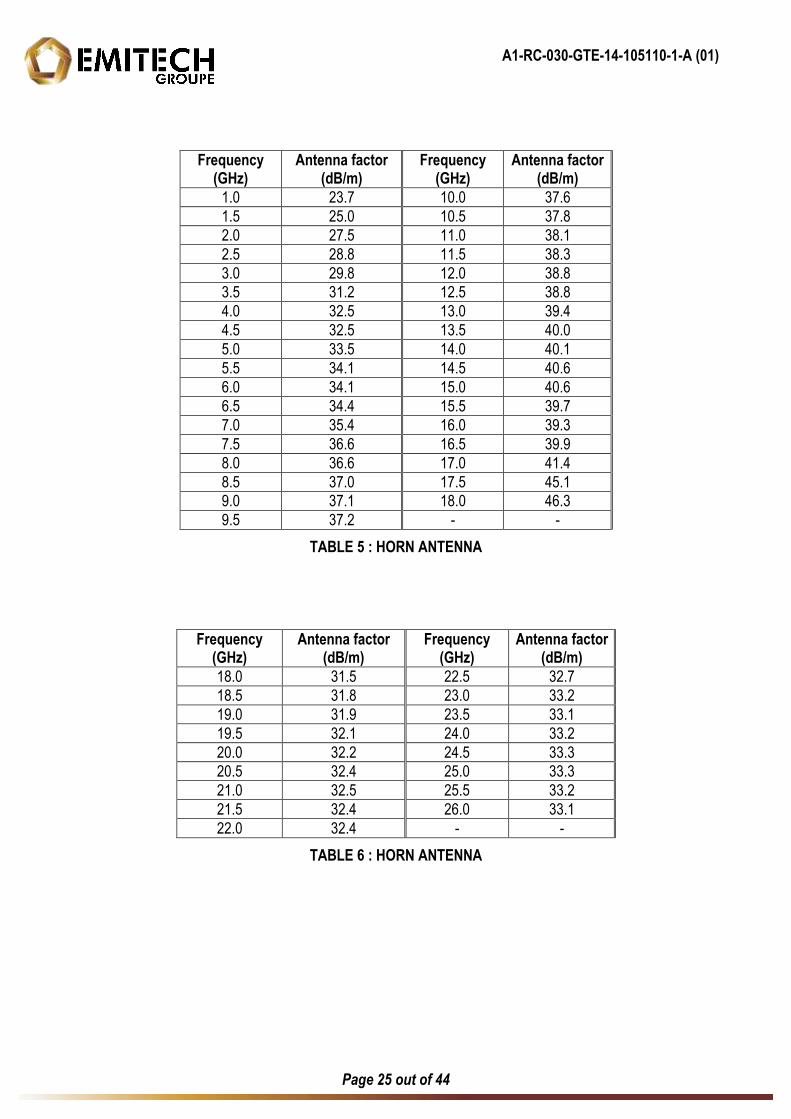
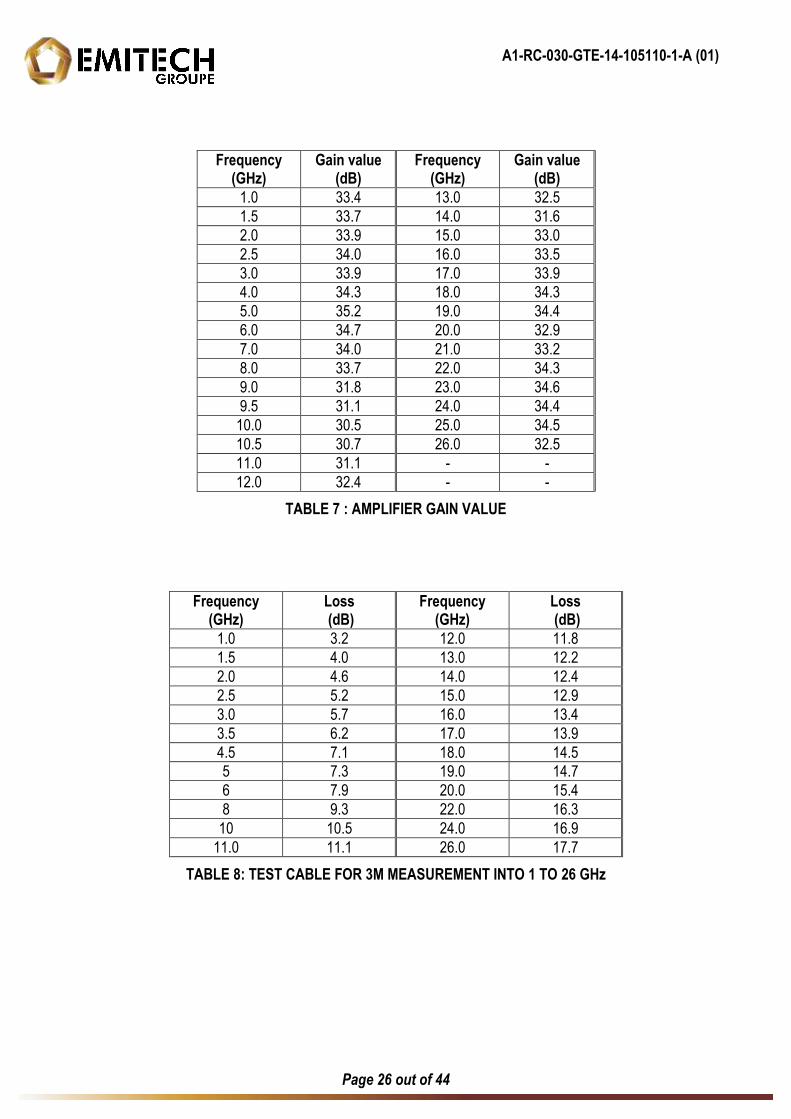
BILL OF MATERIAL The test antenna used for the radiated emission between 9 kHz and 30 MHz is the active loop antenna n°4713. Antenna factors are given in table 1. The test antenna used for the radiated emission between 30 MHz and 1 GHz is the biclog antenna n°4428. Antenna factors are given in table 2. The measuring receiver n°1216 used in the frequency range 30 MHz to 1 GHz has an integrated preamplifier. The spectrum analyzer n°2205 is used in the frequency range 1 GHz to 25 GHz. The test cable used between 9 kHz and 30 MHz to connect the antennas to the receiver for measurements at a distance of 30 meters has losses given in table 3. The test cable used between 30 MHz and 1 GHz to connect the antennas to the receiver for measurements at a distance of 3 meters has losses given in table 4. The test antenna used for the radiated emission between 1 GHz and 18 GHz is the horn antenna n°3374. Factors are given in table 5. The test antenna used for the radiated emission between 18 GHz and 25 GHz is the horn antenna n°1045. Factors are given in table 6. The amplifier n°3229 used to connect the spectrum analyzer to the test cable has gain values given in the table 7. The test cable used between 1 GHz and 26 GHz to connect the horn antenna to the amplifier for measurements at a distance of 3 meters has losses given in table 8.
A1-RC-030-GTE-14-105110-1-A (01)
Page 23 out of 44
Frequency (MHz)
Antenna factor (dB/m)
Frequency (MHz)
Antenna factor (dB/m)
0.009 26.3 0.8 9.9
0.01 25.6 1 10.0
0.015 22.8 1.5 10.1
0.02 21.0 2 10.1
0.03 18.7 3 10.0
0.05 15.4 5 10.0
0.08 12.8 8 9.8
0.1 11.8 10 9.7
0.15 10.5 15 9.2
0.2 9.9 20 8.5
0.3 9.7 25 7.4
0.5 9.7 30 5.6
TABLE 1 : ACTIVE LOOP ANTENNA
Frequency (MHz)
Antenna factor (dB/m)
Frequency (MHz)
Antenna factor (dB/m)
30 20.2 180 9.6
35 17.4 200 11.7
40 13.9 250 12.0
45 12.8 300 13.7
50 10.2 400 16.5
60 7.0 500 18.3
70 6.9 600 20.3
80 8.0 700 21.6
90 9.2 800 22.2
100 11.0 900 23.2
120 12.3 1000 23.7
140 11.4 - -
160 10.9 - -
TABLE 2 : BILOG ANTENNA
A1-RC-030-GTE-14-105110-1-A (01)
Page 24 out of 44
Frequency (MHz)
Loss (dB)
Frequency (MHz)
Loss (dB)
0.009 0.0 6.000 0.5
0.020 0.0 7.000 0.5
0.050 0.0 8.000 0.5
0.100 0.1 9.000 0.6
0.500 0.1 10.00 0.6
1.000 0.2 15.00 0.8
2.000 0.3 20.00 0.9
3.000 0.3 25.00 1.0
4.000 0.4 30.00 1.1
5.000 0.4 - -
TABLE 3 : TEST CABLE FOR 30M MEASUREMENT INTO 9 kHz AND 30 MHz
Frequency (MHz)
Loss (dB)
Frequency (MHz)
Loss (dB)
30 0.7 250 1.8
40 0.7 300 2.1
50 0.9 400 2.3
60 0.9 500 2.5
70 0.9 600 3.0
80 0.9 700 3.4
90 1.1 800 3.6
100 1.1 900 3.9
150 1.4 1000 4.1
200 1.6 - -
TABLE 4 : TEST CABLE FOR 3M MEASUREMENT INTO 30 MHz AND 1 GHz
A1-RC-030-GTE-14-105110-1-A (01)
Page 25 out of 44
Frequency (GHz)
Antenna factor (dB/m)
Frequency (GHz)
Antenna factor (dB/m)
1.0 23.7 10.0 37.6
1.5 25.0 10.5 37.8
2.0 27.5 11.0 38.1
2.5 28.8 11.5 38.3
3.0 29.8 12.0 38.8
3.5 31.2 12.5 38.8
4.0 32.5 13.0 39.4
4.5 32.5 13.5 40.0
5.0 33.5 14.0 40.1
5.5 34.1 14.5 40.6
6.0 34.1 15.0 40.6
6.5 34.4 15.5 39.7
7.0 35.4 16.0 39.3
7.5 36.6 16.5 39.9
8.0 36.6 17.0 41.4
8.5 37.0 17.5 45.1
9.0 37.1 18.0 46.3
9.5 37.2 - -
TABLE 5 : HORN ANTENNA
Frequency (GHz)
Antenna factor (dB/m)
Frequency (GHz)
Antenna factor (dB/m)
18.0 31.5 22.5 32.7
18.5 31.8 23.0 33.2
19.0 31.9 23.5 33.1
19.5 32.1 24.0 33.2
20.0 32.2 24.5 33.3
20.5 32.4 25.0 33.3
21.0 32.5 25.5 33.2
21.5 32.4 26.0 33.1
22.0 32.4 - -
TABLE 6 : HORN ANTENNA
A1-RC-030-GTE-14-105110-1-A (01)
Page 26 out of 44
Frequency (GHz)
Gain value (dB)
Frequency (GHz)
Gain value (dB)
1.0 33.4 13.0 32.5
1.5 33.7 14.0 31.6
2.0 33.9 15.0 33.0
2.5 34.0 16.0 33.5
3.0 33.9 17.0 33.9
4.0 34.3 18.0 34.3
5.0 35.2 19.0 34.4
6.0 34.7 20.0 32.9
7.0 34.0 21.0 33.2
8.0 33.7 22.0 34.3
9.0 31.8 23.0 34.6
9.5 31.1 24.0 34.4
10.0 30.5 25.0 34.5
10.5 30.7 26.0 32.5
11.0 31.1 - -
12.0 32.4 - -
TABLE 7 : AMPLIFIER GAIN VALUE
Frequency (GHz)
Loss (dB)
Frequency (GHz)
Loss (dB)
1.0 3.2 12.0 11.8
1.5 4.0 13.0 12.2
2.0 4.6 14.0 12.4
2.5 5.2 15.0 12.9
3.0 5.7 16.0 13.4
3.5 6.2 17.0 13.9
4.5 7.1 18.0 14.5
5 7.3 19.0 14.7
6 7.9 20.0 15.4
8 9.3 22.0 16.3
10 10.5 24.0 16.9
11.0 11.1 26.0 17.7
TABLE 8: TEST CABLE FOR 3M MEASUREMENT INTO 1 TO 26 GHz
A2-RC-030-GTE-14-105110-1-A (01)
Page 27 out of 44
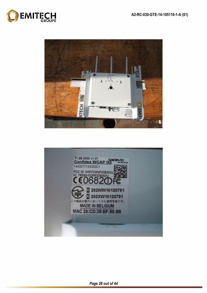
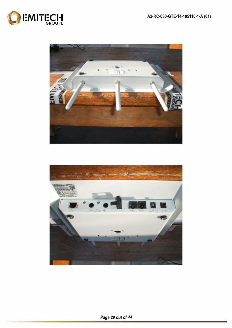
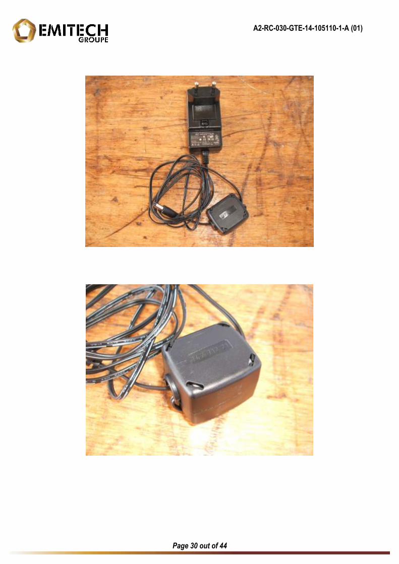
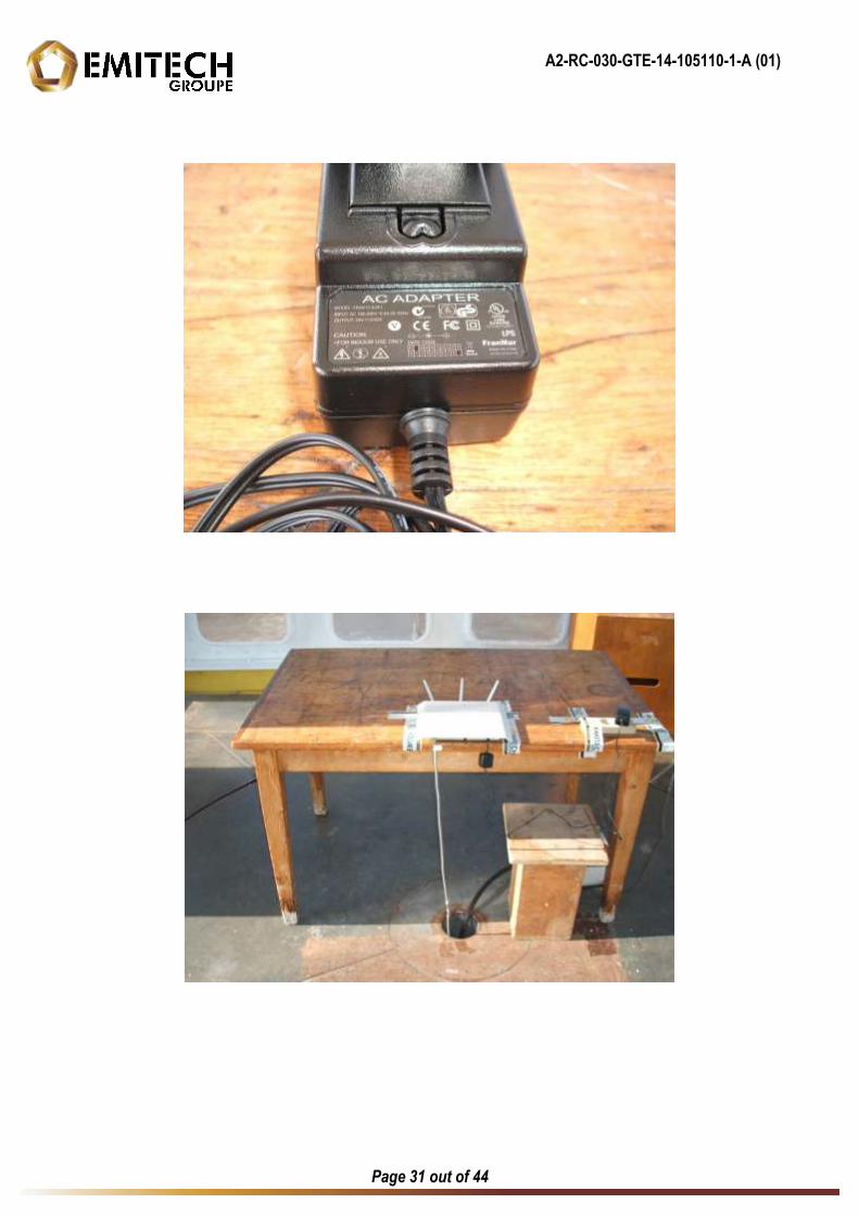
ANNEX 2
EXTERNAL PHOTOGRAPHIES
A2-RC-030-GTE-14-105110-1-A (01)
Page 28 out of 44
A2-RC-030-GTE-14-105110-1-A (01)
Page 29 out of 44
A2-RC-030-GTE-14-105110-1-A (01)
Page 30 out of 44
A2-RC-030-GTE-14-105110-1-A (01)
Page 31 out of 44
A3-RC-030-GTE-14-105110-1-A (01)
Page 32 out of 44
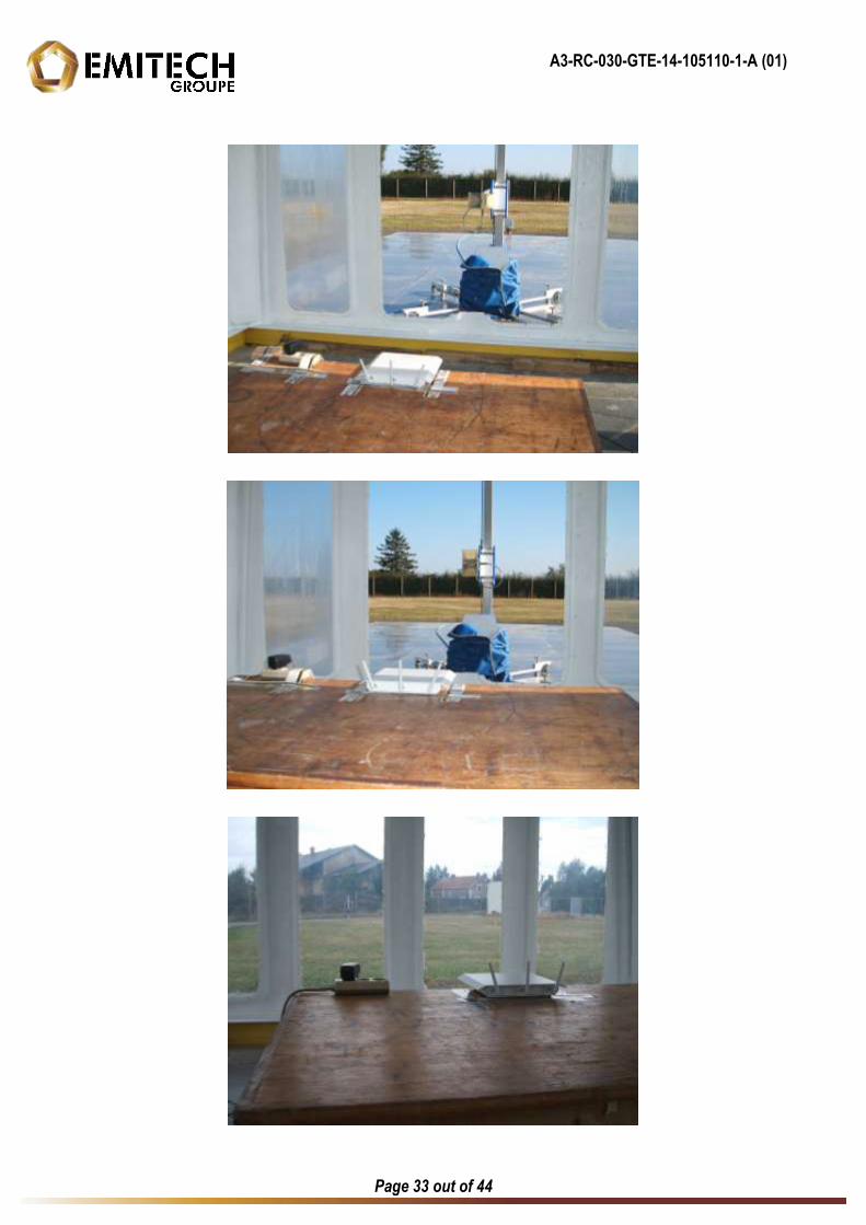
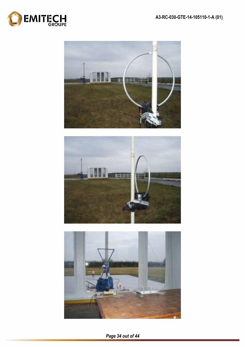
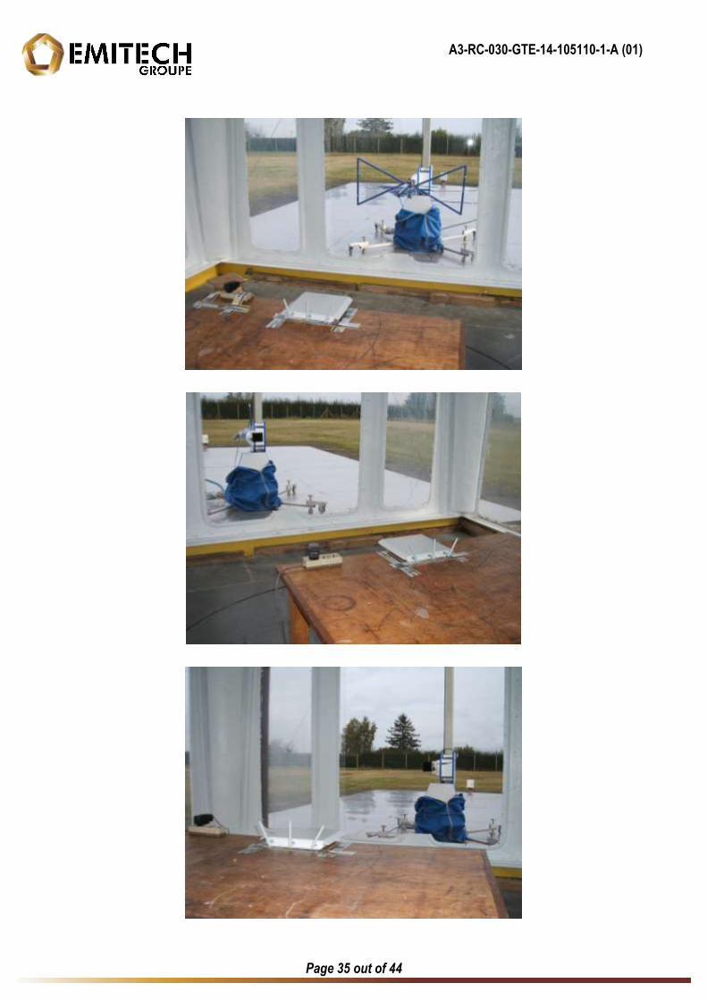
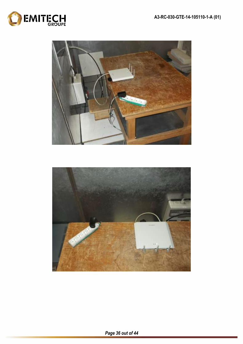
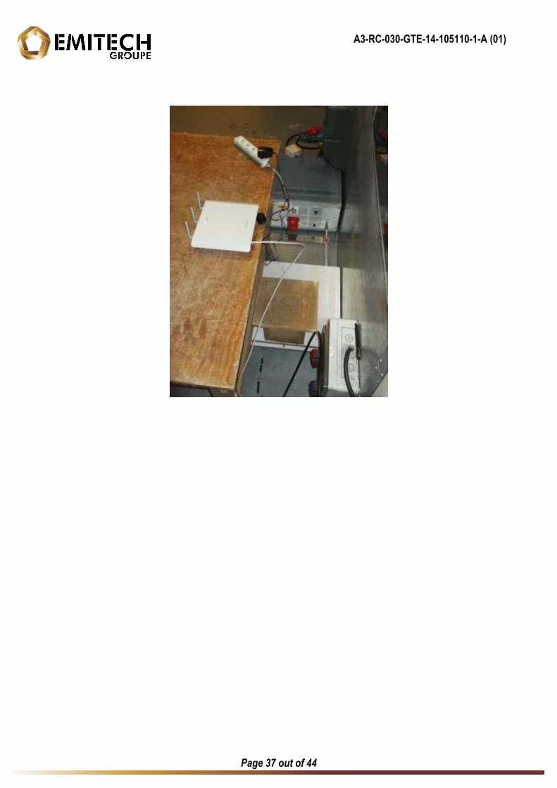
ANNEX 3
TEST SETUP PHOTOGRAPHIES
A3-RC-030-GTE-14-105110-1-A (01)
Page 33 out of 44
A3-RC-030-GTE-14-105110-1-A (01)
Page 34 out of 44
A3-RC-030-GTE-14-105110-1-A (01)
Page 35 out of 44
A3-RC-030-GTE-14-105110-1-A (01)
Page 36 out of 44
A3-RC-030-GTE-14-105110-1-A (01)
Page 37 out of 44

A4-RC-030-GTE-14-105110-1-A (01)
Page 38 out of 44
ANNEX 4
6 dB BANDWIDTH
A4-RC-030-GTE-14-105110-1-A (01)
Page 39 out of 44
Frequency 2412 MHz
Frequency 2442 MHz
A4-RC-030-GTE-14-105110-1-A (01)
Page 40 out of 44
Frequency 2462 MHz
A5-RC-030-GTE-14-105110-1-A (01)
Page 41 out of 44
ANNEX 5
BAND EDGE
A5-RC-030-GTE-14-105110-1-A (01)
Page 42 out of 44
A6-RC-030-GTE-14-105110-1-A (01)
Page 43 out of 44
ANNEX 6
CALIBRATION DATES
A6-RC-030-GTE-14-105110-1-A (01)
Page 44 out of 44
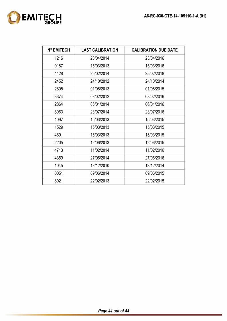
N° EMITECH LAST CALIBRATION CALIBRATION DUE DATE
1216 23/04/2014 23/04/2016
0187 15/03/2013 15/03/2016
4428 25/02/2014 25/02/2018
2452 24/10/2012 24/10/2014
2805 01/08/2013 01/08/2015
3374 08/02/2012 08/02/2016
2864 06/01/2014 06/01/2016
8063 23/07/2014 23/07/2016
1097 15/03/2013 15/03/2015
1529 15/03/2013 15/03/2015
4691 15/03/2013 15/03/2015
2205 12/06/2013 12/06/2015
4713 11/02/2014 11/02/2016
4359 27/06/2014 27/06/2016
1045 13/12/2010 13/12/2014
0051 09/06/2014 09/06/2015
8021 22/02/2013 22/02/2015