Embed Size (px)
Citation preview
MICHIGAN OHIO UNIVERSITY TRANSPORTATION CENTER Alternate energy and system mobility to stimulate economic development.
Report No: MIOH UTC AF12p1-2 2010-Final
MDOT No. RC1545
IMPROVING THE ENERGY DENSITY OF HYDRAULIC HYBRID VEHICLES (HHVS)
AND EVALUATING PLUG-IN HHVS
Final Report
Project Team
Dr. Mark Schumack
Sujay Bodke Department of Mechanical Engineering
University of Detroit Mercy 4001 W. McNichols Road
Detroit, MI 48221
Undertaken in conjunction with a project led by Dr. Mohammad Elahinia, Dr. Walter Olson, and Dr. Mark Vonderembse
The University of Toledo
ii
Report No: MIOH UTC AF12p1-2 2010-Final
AF 12, Series, Projects 1 & 2, May, 2010
FINAL REPORT
Developed by: Dr. Mark Schumack
Principal Investigator, UDM [email protected]
313-993-3370 In conjunction with: Dr. Mohammad Elahinia Principal Investigator, UT
[email protected] 419-530-8224
SPONSORS This is a Michigan Ohio University Transportation Center project supported by the U.S. Department of Transportation, the Michigan Department of Transportation and the University of Detroit Mercy.
ACKNOWLEDGEMENT The Project Team would like to acknowledge collaboration with researchers from The University of Toledo, Dynamic and Smart Systems Laboratory, MIME Department.
DISCLAIMER The contents of this report reflect the views of the authors, who are responsible for the facts and the accuracy of the information presented herein. This document is disseminated under the sponsorship of the Department of Transportation University Transportation Centers Program, in the interest of information exchange. The U.S. Government assumes no liability for the contents or use thereof. The opinions, findings and conclusions expressed in this publication are those of the authors and not necessarily those of the Michigan State Transportation Commission, the Michigan Department of Transportation, or the Federal Highway Administration.
iii
Technical Report Documentation Page 1. Report No.
RC-1545 2. Government Accession No.
3. MDOT Project Manager
Niles Annelin
4. Title and Subtitle
Michigan Ohio University Transportation Center Subtitle: “Improving the Energy Density of Hydraulic Hybrid Vehicles (HHVs) and Evaluating Plug-In HHVs”
5. Report Date
May 2010
6. Performing Organization Code
7. Author(s)
Dr. MarkSchumack, University of Detroit Mercy
8. Performing Org. Report No.
MIOH UTC AF12p1-2 2010-Final
9. Performing Organization Name and Address
Michigan Ohio University Transportation Center University of Detroit Mercy, Detroit, MI 48221 and University of Detroit Mercy, Detroit, MI 48221
10. Work Unit No. (TRAIS)
11. Contract No.
2007-0538
11(a). Authorization No.
12. Sponsoring Agency Name and Address
Michigan Department of Transportation Van Wagoner Building, 425 West Ottawa P. O. Box 30050, Lansing, Michigan 48909
13. Type of Report & Period Covered
Research, October 2007- December 2009
14. Sponsoring Agency Code
15. Supplementary Notes
Additional Sponsors: US DOT Research & Innovative Technology Administration, University of Detroit Mercy 16. Abstract
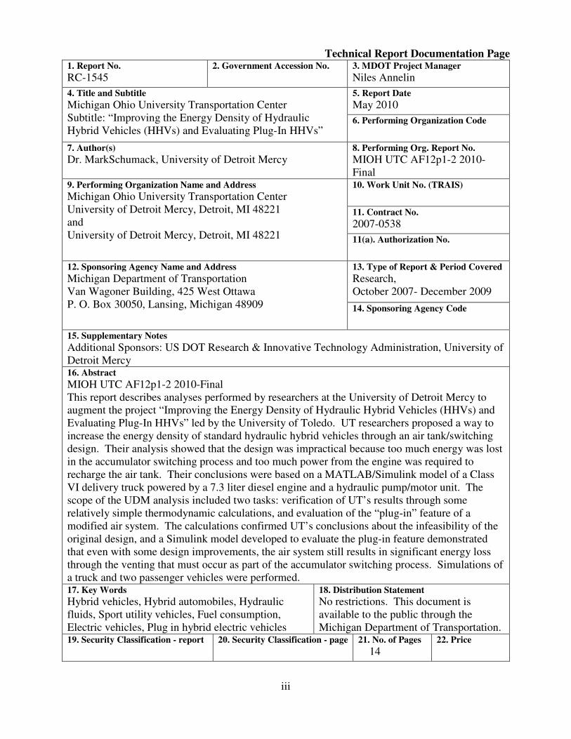
MIOH UTC AF12p1-2 2010-Final This report describes analyses performed by researchers at the University of Detroit Mercy to augment the project “Improving the Energy Density of Hydraulic Hybrid Vehicles (HHVs) and Evaluating Plug-In HHVs” led by the University of Toledo. UT researchers proposed a way to increase the energy density of standard hydraulic hybrid vehicles through an air tank/switching design. Their analysis showed that the design was impractical because too much energy was lost in the accumulator switching process and too much power from the engine was required to recharge the air tank. Their conclusions were based on a MATLAB/Simulink model of a Class VI delivery truck powered by a 7.3 liter diesel engine and a hydraulic pump/motor unit. The scope of the UDM analysis included two tasks: verification of UT’s results through some relatively simple thermodynamic calculations, and evaluation of the “plug-in” feature of a modified air system. The calculations confirmed UT’s conclusions about the infeasibility of the original design, and a Simulink model developed to evaluate the plug-in feature demonstrated that even with some design improvements, the air system still results in significant energy loss through the venting that must occur as part of the accumulator switching process. Simulations of a truck and two passenger vehicles were performed. 17. Key Words
Hybrid vehicles, Hybrid automobiles, Hydraulic fluids, Sport utility vehicles, Fuel consumption, Electric vehicles, Plug in hybrid electric vehicles
18. Distribution Statement
No restrictions. This document is available to the public through the Michigan Department of Transportation.
19. Security Classification - report
20. Security Classification - page
21. No. of Pages
14 22. Price
iv
Abstract This report describes analyses performed by researchers at the University of Detroit Mercy to augment the project “Improving the Energy Density of Hydraulic Hybrid Vehicles (HHVs) and Evaluating Plug-In HHVs” led by the University of Toledo. UT researchers proposed a way to increase the energy density of standard hydraulic hybrid vehicles through an air tank/switching design. Their analysis showed that the design was impractical because too much energy was lost in the accumulator switching process and too much power from the engine was required to recharge the air tank. Their conclusions were based on a MATLAB/Simulink model of a Class VI delivery truck powered by a 7.3 liter diesel engine and a hydraulic pump/motor unit. The scope of the UDM analysis included two tasks: verification of UT’s results through some relatively simple thermodynamic calculations, and evaluation of the “plug-in” feature of a modified air system. The calculations confirmed UT’s conclusions about the infeasibility of the original design, and a Simulink model developed to evaluate the plug-in feature demonstrated that even with some design improvements, the air system still results in significant energy loss through the venting that must occur as part of the accumulator switching process. Simulations of a truck and two passenger vehicles were performed.
v
Table of Contents ACKNOWLEDGEMENTS ........................................................................................................... ii ABSTRACT .................................................................................................................................. iv LIST OF TABLES ...........................................................................................................................v LIST OF FIGURES ........................................................................................................................ v 1. INTRODUCTION ..................................................................................................................1 2. DESCRIPTION OF THE UT SYSTEM ................................................................................2 3. ANALYSIS OF UT SYSTEM ...............................................................................................3 4. THE ALTERNATE DESIGN ................................................................................................7 5. RESULTS .............................................................................................................................10 6. EVALUATION OF PLUG-IN FEATURE ..........................................................................12 7. CONCLUSIONS ..................................................................................................................13 8. REFERENCES .....................................................................................................................14
List of Tables
Table 1 Key Specifications used in Calculating Energy Quantities for the Air/Hydraulic System ........................................................................................................................ 6 Table 2 Calculated Ideal Energies ................................................................................................6 Table 3 Comparison between UT and UDM Designs for Calculated Ideal Energies and Range at Constant Speed ..........................................................................................10 Table 4 Specifications of the Truck and the Cars .......................................................................11 Table 5 Car and Truck Results for FUDS Simulation ................................................................11 Table 6 Plug in Results for Truck and Car .................................................................................12
List of Figures
Figure 1 University of Toledo’s Proposed Concept Hydraulic Hybrid System3 .........................2 Figure 2 Conceptual Separation of Air, Nitrogen, and Oil by Pistons ...........................................3 Figure 3 Accumulator with Bellows Arrangement ........................................................................8 Figure 4 Schematic for the Proposed System ................................................................................9 Figure 5 The Simulink Model ........................................................................................................9
Figure 6 Velocity vs. Time Curve from FUDS ............................................................................10
1
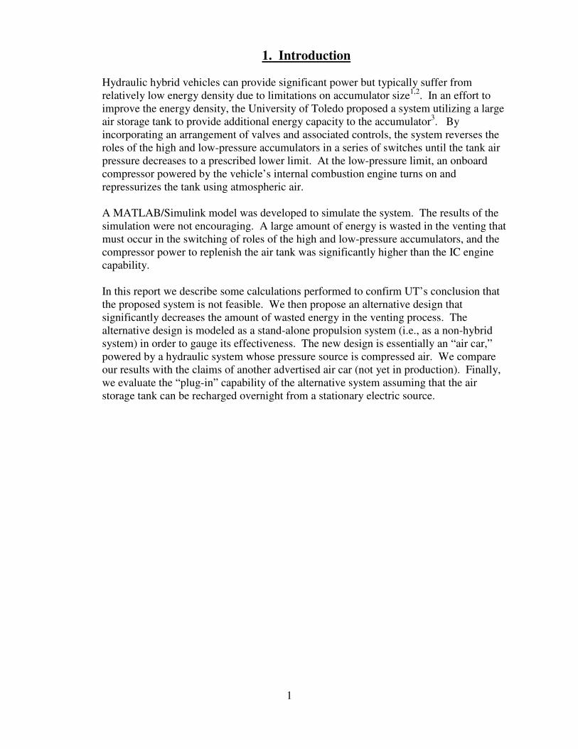
1. Introduction
Hydraulic hybrid vehicles can provide significant power but typically suffer from relatively low energy density due to limitations on accumulator size1,2. In an effort to improve the energy density, the University of Toledo proposed a system utilizing a large air storage tank to provide additional energy capacity to the accumulator3. By incorporating an arrangement of valves and associated controls, the system reverses the roles of the high and low-pressure accumulators in a series of switches until the tank air pressure decreases to a prescribed lower limit. At the low-pressure limit, an onboard compressor powered by the vehicle’s internal combustion engine turns on and repressurizes the tank using atmospheric air.
A MATLAB/Simulink model was developed to simulate the system. The results of the simulation were not encouraging. A large amount of energy is wasted in the venting that must occur in the switching of roles of the high and low-pressure accumulators, and the compressor power to replenish the air tank was significantly higher than the IC engine capability.
In this report we describe some calculations performed to confirm UT’s conclusion that the proposed system is not feasible. We then propose an alternative design that significantly decreases the amount of wasted energy in the venting process. The alternative design is modeled as a stand-alone propulsion system (i.e., as a non-hybrid system) in order to gauge its effectiveness. The new design is essentially an “air car,” powered by a hydraulic system whose pressure source is compressed air. We compare our results with the claims of another advertised air car (not yet in production). Finally, we evaluate the “plug-in” capability of the alternative system assuming that the air storage tank can be recharged overnight from a stationary electric source.
2
2. Description of the UT System
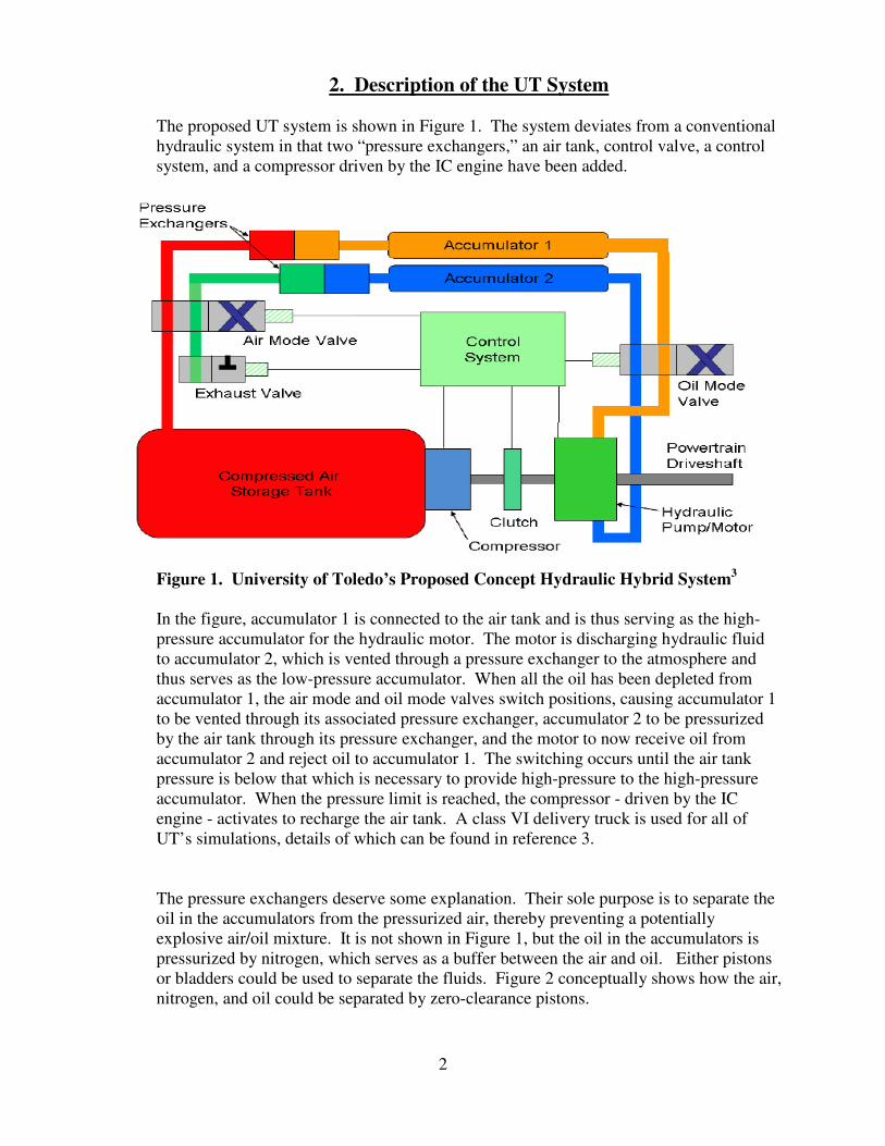
The proposed UT system is shown in Figure 1. The system deviates from a conventional hydraulic system in that two “pressure exchangers,” an air tank, control valve, a control system, and a compressor driven by the IC engine have been added.
Figure 1. University of Toledo’s Proposed Concept Hydraulic Hybrid System3
In the figure, accumulator 1 is connected to the air tank and is thus serving as the high-pressure accumulator for the hydraulic motor. The motor is discharging hydraulic fluid to accumulator 2, which is vented through a pressure exchanger to the atmosphere and thus serves as the low-pressure accumulator. When all the oil has been depleted from accumulator 1, the air mode and oil mode valves switch positions, causing accumulator 1 to be vented through its associated pressure exchanger, accumulator 2 to be pressurized by the air tank through its pressure exchanger, and the motor to now receive oil from accumulator 2 and reject oil to accumulator 1. The switching occurs until the air tank pressure is below that which is necessary to provide high-pressure to the high-pressure accumulator. When the pressure limit is reached, the compressor - driven by the IC engine - activates to recharge the air tank. A class VI delivery truck is used for all of UT’s simulations, details of which can be found in reference 3.
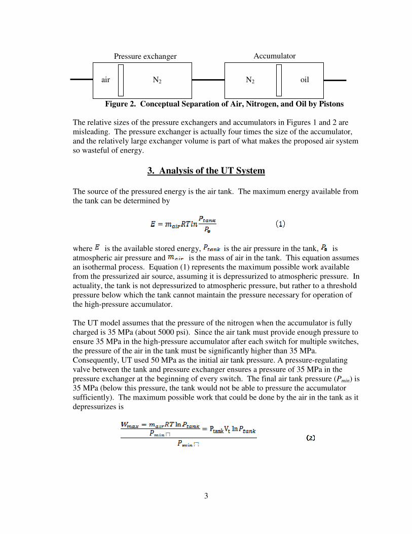
The pressure exchangers deserve some explanation. Their sole purpose is to separate the oil in the accumulators from the pressurized air, thereby preventing a potentially explosive air/oil mixture. It is not shown in Figure 1, but the oil in the accumulators is pressurized by nitrogen, which serves as a buffer between the air and oil. Either pistons or bladders could be used to separate the fluids. Figure 2 conceptually shows how the air, nitrogen, and oil could be separated by zero-clearance pistons.
3
Figure 2. Conceptual Separation of Air, Nitrogen, and Oil by Pistons
The relative sizes of the pressure exchangers and accumulators in Figures 1 and 2 are misleading. The pressure exchanger is actually four times the size of the accumulator, and the relatively large exchanger volume is part of what makes the proposed air system so wasteful of energy.
3. Analysis of the UT System
The source of the pressured energy is the air tank. The maximum energy available from the tank can be determined by
where is the available stored energy, is the air pressure in the tank, is atmospheric air pressure and is the mass of air in the tank. This equation assumes an isothermal process. Equation (1) represents the maximum possible work available from the pressurized air source, assuming it is depressurized to atmospheric pressure. In actuality, the tank is not depressurized to atmospheric pressure, but rather to a threshold pressure below which the tank cannot maintain the pressure necessary for operation of the high-pressure accumulator.
The UT model assumes that the pressure of the nitrogen when the accumulator is fully charged is 35 MPa (about 5000 psi). Since the air tank must provide enough pressure to ensure 35 MPa in the high-pressure accumulator after each switch for multiple switches, the pressure of the air in the tank must be significantly higher than 35 MPa. Consequently, UT used 50 MPa as the initial air tank pressure. A pressure-regulating valve between the tank and pressure exchanger ensures a pressure of 35 MPa in the pressure exchanger at the beginning of every switch. The final air tank pressure (Pmin) is 35 MPa (below this pressure, the tank would not be able to pressure the accumulator sufficiently). The maximum possible work that could be done by the air in the tank as it depressurizes is
N2 N2 air oil
Accumulator Pressure exchanger
4
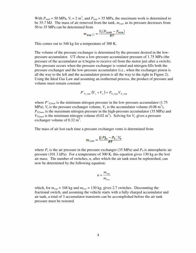
With Ptank = 50 MPa, Vt = 2 m3, and Pmin = 35 MPa, the maximum work is determined to be 35.7 MJ. The mass of air removed from the tank, mexp, as its pressure decreases from 50 to 35 MPa can be determined from
This comes out to 348 kg for a temperature of 300 K. The volume of the pressure exchanger is determined by the pressure desired in the low-pressure accumulator. UT chose a low-pressure accumulator pressure of 1.75 MPa (the pressure of the accumulator as it begins to receive oil from the motor just after a switch). This pressure occurs when the pressure exchanger is vented and nitrogen fills both the pressure exchanger and the low-pressure accumulator (i.e., when the exchanger piston is all the way to the left and the accumulator piston is all the way to the right in Figure 2). Using the Ideal Gas Law and assuming an isothermal process, the product of pressure and volume must remain constant:
( ) minmaxmin 222' NNaeN VPVVP =+
where P’N2min is the minimum nitrogen pressure in the low-pressure accumulator (1.75 MPa), Ve is the pressure exchanger volume, Va is the accumulator volume (0.08 m3), PN2max is the maximum nitrogen pressure in the high-pressure accumulator (35 MPa) and VN2min is the minimum nitrogen volume (0.02 m3). Solving for Ve gives a pressure exchanger volume of 0.32 m3. The mass of air lost each time a pressure exchanger vents is determined from
where Pe is the air pressure in the pressure exchanger (35 MPa) and P0 is atmospheric air pressure (101.3 kPa). For a temperature of 300 K, this equation gives 130 kg as the lost air mass. The number of switches, n, after which the air tank must be replenished, can now be determined by the following equation:
lossm
mn
exp=
which, for mexp = 348 kg and mloss = 130 kg, gives 2.7 switches. Discounting the fractional switch, and assuming the vehicle starts with a fully charged accumulator and air tank, a total of 3 accumulator transients can be accomplished before the air tank pressure must be restored.
5
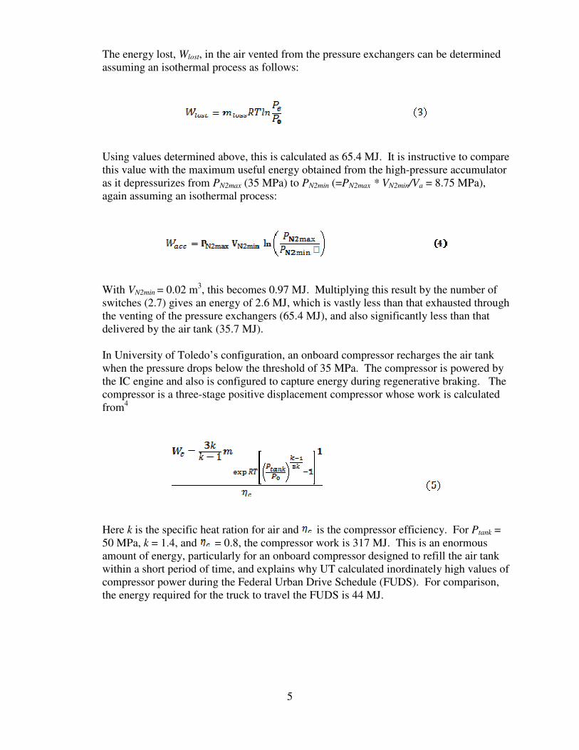
The energy lost, Wlost, in the air vented from the pressure exchangers can be determined assuming an isothermal process as follows:
Using values determined above, this is calculated as 65.4 MJ. It is instructive to compare this value with the maximum useful energy obtained from the high-pressure accumulator as it depressurizes from PN2max (35 MPa) to PN2min (=PN2max * VN2min/Va = 8.75 MPa), again assuming an isothermal process:
With VN2min = 0.02 m3, this becomes 0.97 MJ. Multiplying this result by the number of switches (2.7) gives an energy of 2.6 MJ, which is vastly less than that exhausted through the venting of the pressure exchangers (65.4 MJ), and also significantly less than that delivered by the air tank (35.7 MJ). In University of Toledo’s configuration, an onboard compressor recharges the air tank when the pressure drops below the threshold of 35 MPa. The compressor is powered by the IC engine and also is configured to capture energy during regenerative braking. The compressor is a three-stage positive displacement compressor whose work is calculated from4
Here k is the specific heat ration for air and is the compressor efficiency. For Ptank = 50 MPa, k = 1.4, and = 0.8, the compressor work is 317 MJ. This is an enormous amount of energy, particularly for an onboard compressor designed to refill the air tank within a short period of time, and explains why UT calculated inordinately high values of compressor power during the Federal Urban Drive Schedule (FUDS). For comparison, the energy required for the truck to travel the FUDS is 44 MJ.
6
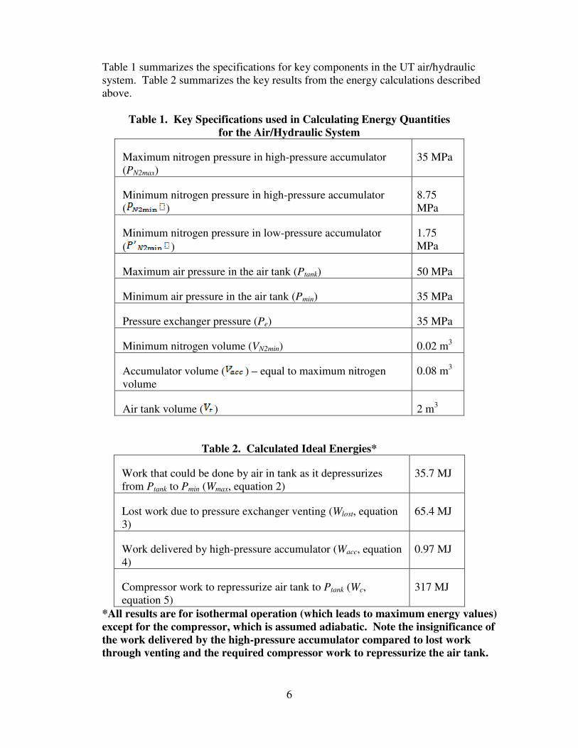
Table 1 summarizes the specifications for key components in the UT air/hydraulic system. Table 2 summarizes the key results from the energy calculations described above.
Table 1. Key Specifications used in Calculating Energy Quantities
for the Air/Hydraulic System
Maximum nitrogen pressure in high-pressure accumulator (PN2max)
35 MPa
Minimum nitrogen pressure in high-pressure accumulator ( )
8.75 MPa
Minimum nitrogen pressure in low-pressure accumulator
( )
1.75 MPa
Maximum air pressure in the air tank (Ptank) 50 MPa
Minimum air pressure in the air tank (Pmin) 35 MPa
Pressure exchanger pressure (Pe) 35 MPa
Minimum nitrogen volume (VN2min) 0.02 m3
Accumulator volume ( ) – equal to maximum nitrogen volume
0.08 m3
Air tank volume ( ) 2 m3
Table 2. Calculated Ideal Energies*
Work that could be done by air in tank as it depressurizes from Ptank to Pmin (Wmax, equation 2)
35.7 MJ
Lost work due to pressure exchanger venting (Wlost, equation 3)
65.4 MJ
Work delivered by high-pressure accumulator (Wacc, equation 4)
0.97 MJ
Compressor work to repressurize air tank to Ptank (Wc, equation 5)
317 MJ
*All results are for isothermal operation (which leads to maximum energy values)
except for the compressor, which is assumed adiabatic. Note the insignificance of
the work delivered by the high-pressure accumulator compared to lost work
through venting and the required compressor work to repressurize the air tank.
7
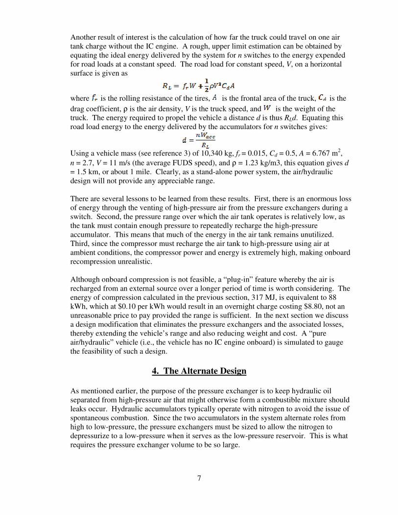
Another result of interest is the calculation of how far the truck could travel on one air tank charge without the IC engine. A rough, upper limit estimation can be obtained by equating the ideal energy delivered by the system for n switches to the energy expended for road loads at a constant speed. The road load for constant speed, V, on a horizontal surface is given as
where is the rolling resistance of the tires, is the frontal area of the truck, is the
drag coefficient, ρ is the air density, V is the truck speed, and is the weight of the truck. The energy required to propel the vehicle a distance d is thus RLd. Equating this road load energy to the energy delivered by the accumulators for n switches gives:
Using a vehicle mass (see reference 3) of 10,340 kg, fr = 0.015, Cd = 0.5, A = 6.767 m2,
n = 2.7, V = 11 m/s (the average FUDS speed), and ρ = 1.23 kg/m3, this equation gives d = 1.5 km, or about 1 mile. Clearly, as a stand-alone power system, the air/hydraulic design will not provide any appreciable range.
There are several lessons to be learned from these results. First, there is an enormous loss of energy through the venting of high-pressure air from the pressure exchangers during a switch. Second, the pressure range over which the air tank operates is relatively low, as the tank must contain enough pressure to repeatedly recharge the high-pressure accumulator. This means that much of the energy in the air tank remains unutilized. Third, since the compressor must recharge the air tank to high-pressure using air at ambient conditions, the compressor power and energy is extremely high, making onboard recompression unrealistic.
Although onboard compression is not feasible, a “plug-in” feature whereby the air is recharged from an external source over a longer period of time is worth considering. The energy of compression calculated in the previous section, 317 MJ, is equivalent to 88 kWh, which at $0.10 per kWh would result in an overnight charge costing $8.80, not an unreasonable price to pay provided the range is sufficient. In the next section we discuss a design modification that eliminates the pressure exchangers and the associated losses, thereby extending the vehicle’s range and also reducing weight and cost. A “pure air/hydraulic” vehicle (i.e., the vehicle has no IC engine onboard) is simulated to gauge the feasibility of such a design.
4. The Alternate Design
As mentioned earlier, the purpose of the pressure exchanger is to keep hydraulic oil separated from high-pressure air that might otherwise form a combustible mixture should leaks occur. Hydraulic accumulators typically operate with nitrogen to avoid the issue of spontaneous combustion. Since the two accumulators in the system alternate roles from high to low-pressure, the pressure exchangers must be sized to allow the nitrogen to depressurize to a low-pressure when it serves as the low-pressure reservoir. This is what requires the pressure exchanger volume to be so large.
8
If, however, the danger of an explosive oil/air mixture could be eliminated, the accumulators could operate using air rather than nitrogen as the pressure source, and the pressure exchangers could be removed from the design.
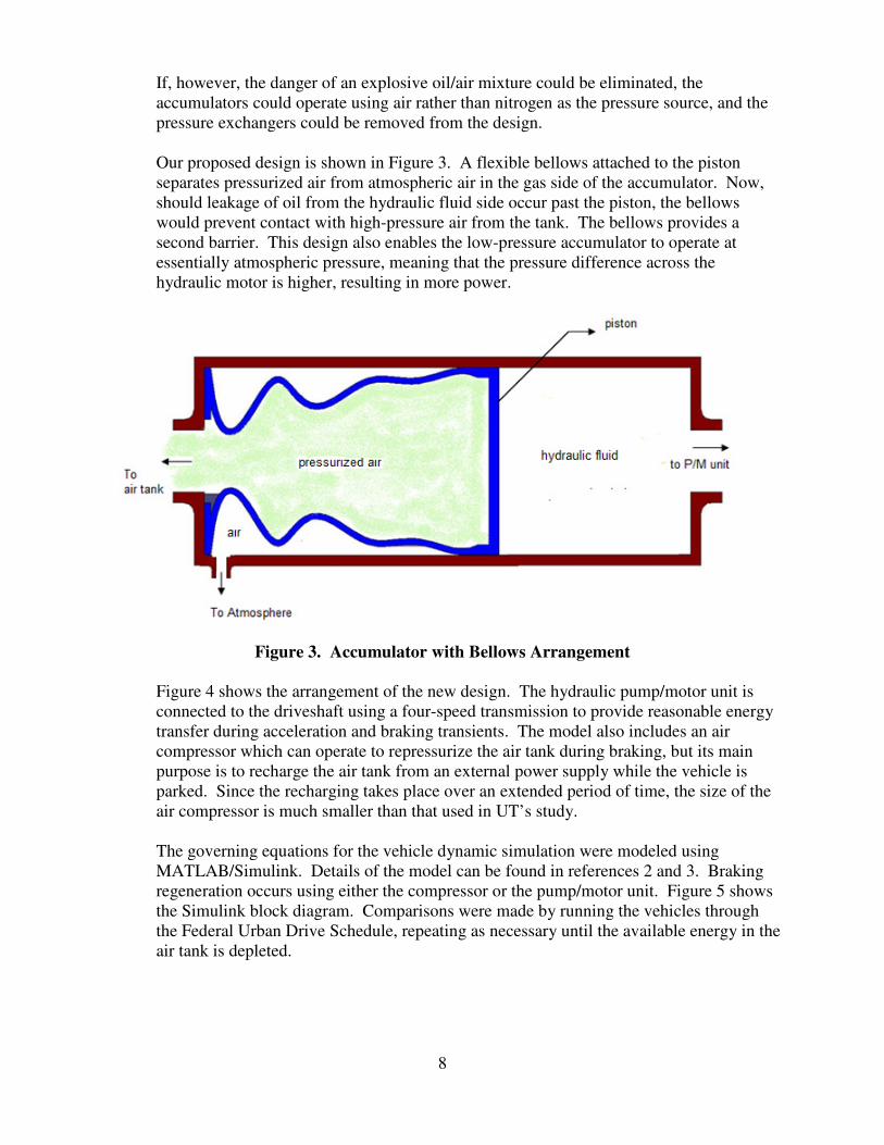
Our proposed design is shown in Figure 3. A flexible bellows attached to the piston separates pressurized air from atmospheric air in the gas side of the accumulator. Now, should leakage of oil from the hydraulic fluid side occur past the piston, the bellows would prevent contact with high-pressure air from the tank. The bellows provides a second barrier. This design also enables the low-pressure accumulator to operate at essentially atmospheric pressure, meaning that the pressure difference across the hydraulic motor is higher, resulting in more power.
Figure 3. Accumulator with Bellows Arrangement
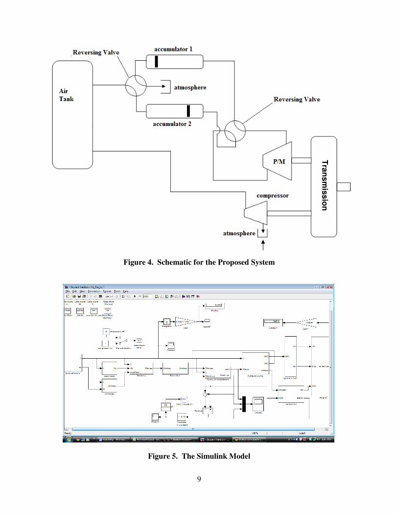
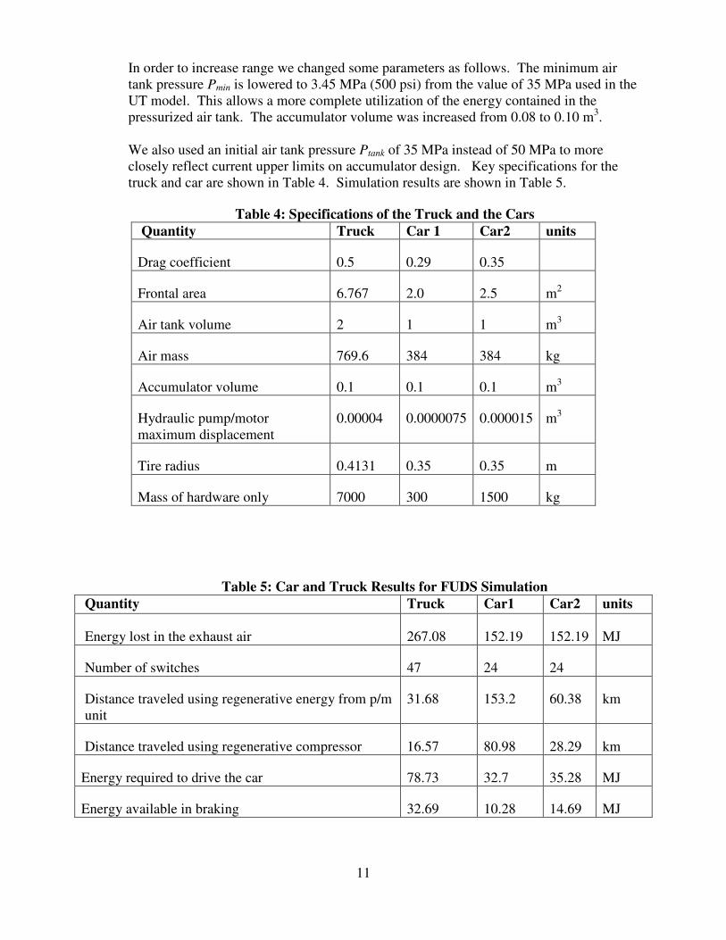
Figure 4 shows the arrangement of the new design. The hydraulic pump/motor unit is connected to the driveshaft using a four-speed transmission to provide reasonable energy transfer during acceleration and braking transients. The model also includes an air compressor which can operate to repressurize the air tank during braking, but its main purpose is to recharge the air tank from an external power supply while the vehicle is parked. Since the recharging takes place over an extended period of time, the size of the air compressor is much smaller than that used in UT’s study. The governing equations for the vehicle dynamic simulation were modeled using MATLAB/Simulink. Details of the model can be found in references 2 and 3. Braking regeneration occurs using either the compressor or the pump/motor unit. Figure 5 shows the Simulink block diagram. Comparisons were made by running the vehicles through the Federal Urban Drive Schedule, repeating as necessary until the available energy in the air tank is depleted.
9
Figure 4. Schematic for the Proposed System
Figure 5. The Simulink Model
Tra
ns
mis
sio
n
10
5. Results
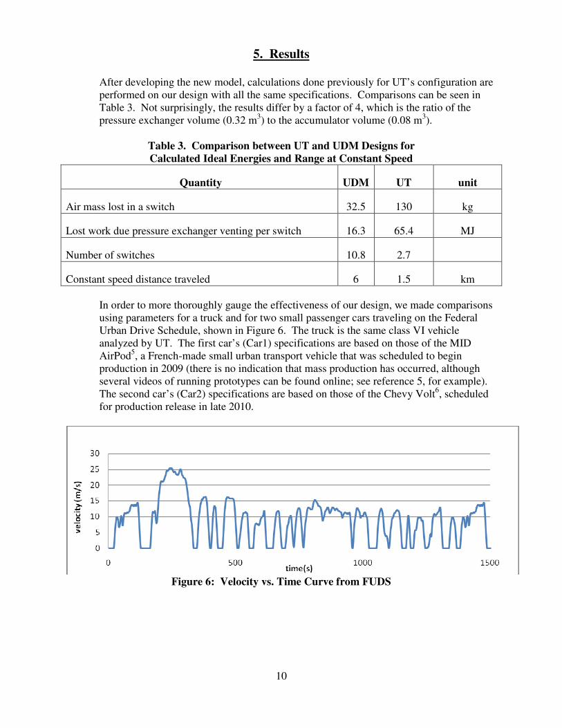
After developing the new model, calculations done previously for UT’s configuration are performed on our design with all the same specifications. Comparisons can be seen in Table 3. Not surprisingly, the results differ by a factor of 4, which is the ratio of the pressure exchanger volume (0.32 m3) to the accumulator volume (0.08 m3).
Table 3. Comparison between UT and UDM Designs for
Calculated Ideal Energies and Range at Constant Speed
Quantity UDM UT unit
Air mass lost in a switch 32.5 130 kg
Lost work due pressure exchanger venting per switch 16.3 65.4 MJ
Number of switches 10.8 2.7
Constant speed distance traveled 6 1.5 km
In order to more thoroughly gauge the effectiveness of our design, we made comparisons using parameters for a truck and for two small passenger cars traveling on the Federal Urban Drive Schedule, shown in Figure 6. The truck is the same class VI vehicle analyzed by UT. The first car’s (Car1) specifications are based on those of the MID AirPod5, a French-made small urban transport vehicle that was scheduled to begin production in 2009 (there is no indication that mass production has occurred, although several videos of running prototypes can be found online; see reference 5, for example). The second car’s (Car2) specifications are based on those of the Chevy Volt6, scheduled for production release in late 2010.
Figure 6: Velocity vs. Time Curve from FUDS
11
In order to increase range we changed some parameters as follows. The minimum air tank pressure Pmin is lowered to 3.45 MPa (500 psi) from the value of 35 MPa used in the UT model. This allows a more complete utilization of the energy contained in the pressurized air tank. The accumulator volume was increased from 0.08 to 0.10 m3. We also used an initial air tank pressure Ptank of 35 MPa instead of 50 MPa to more closely reflect current upper limits on accumulator design. Key specifications for the truck and car are shown in Table 4. Simulation results are shown in Table 5.
Table 4: Specifications of the Truck and the Cars
Quantity Truck Car 1 Car2 units
Drag coefficient 0.5 0.29 0.35
Frontal area 6.767 2.0 2.5 m2
Air tank volume 2 1 1 m3
Air mass 769.6 384 384 kg
Accumulator volume 0.1 0.1 0.1 m3
Hydraulic pump/motor maximum displacement
0.00004 0.0000075 0.000015 m3
Tire radius 0.4131 0.35 0.35 m
Mass of hardware only 7000 300 1500 kg
Table 5: Car and Truck Results for FUDS Simulation
Quantity Truck Car1 Car2 units
Energy lost in the exhaust air 267.08 152.19 152.19 MJ
Number of switches 47 24 24
Distance traveled using regenerative energy from p/m unit
31.68 153.2 60.38 km
Distance traveled using regenerative compressor 16.57 80.98 28.29 km
Energy required to drive the car 78.73 32.7 35.28 MJ
Energy available in braking 32.69 10.28 14.69 MJ
12
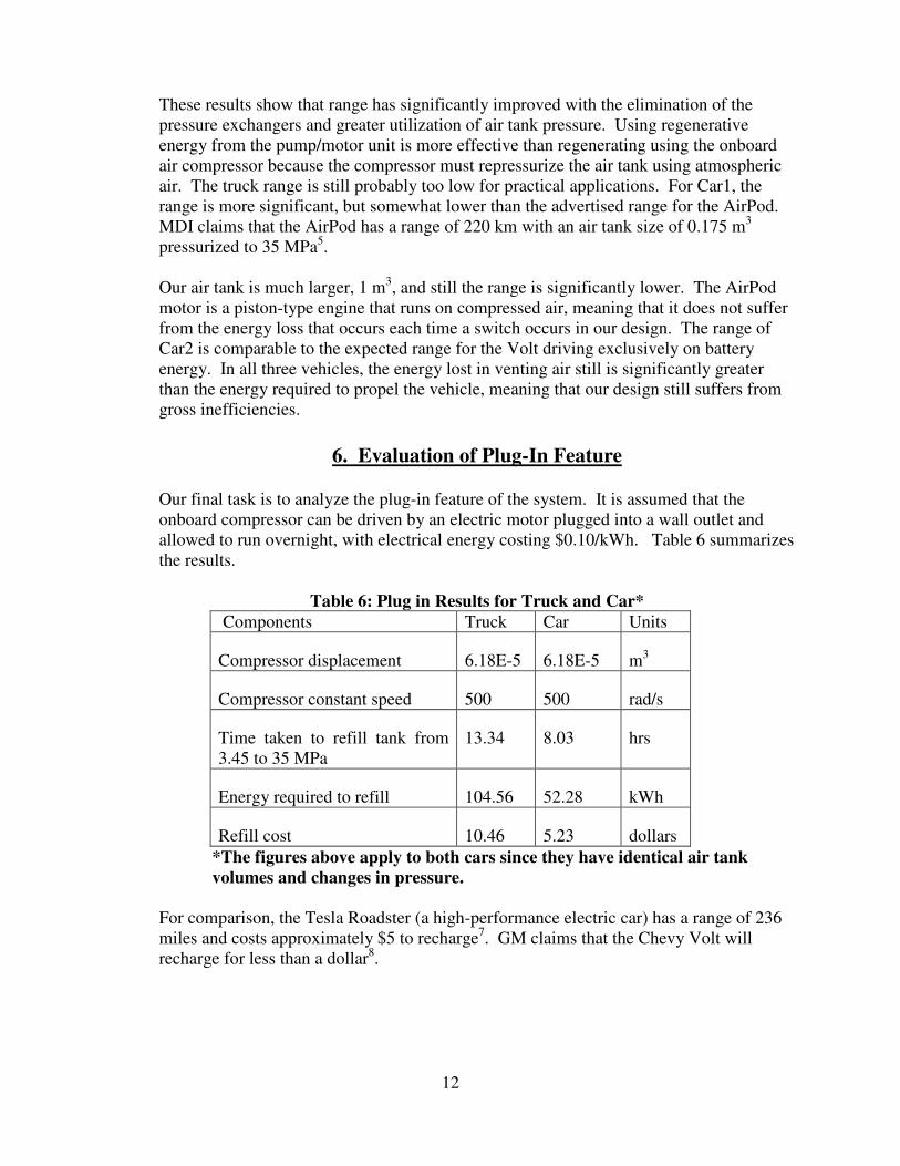
These results show that range has significantly improved with the elimination of the pressure exchangers and greater utilization of air tank pressure. Using regenerative energy from the pump/motor unit is more effective than regenerating using the onboard air compressor because the compressor must repressurize the air tank using atmospheric air. The truck range is still probably too low for practical applications. For Car1, the range is more significant, but somewhat lower than the advertised range for the AirPod. MDI claims that the AirPod has a range of 220 km with an air tank size of 0.175 m3 pressurized to 35 MPa5. Our air tank is much larger, 1 m3, and still the range is significantly lower. The AirPod motor is a piston-type engine that runs on compressed air, meaning that it does not suffer from the energy loss that occurs each time a switch occurs in our design. The range of Car2 is comparable to the expected range for the Volt driving exclusively on battery energy. In all three vehicles, the energy lost in venting air still is significantly greater than the energy required to propel the vehicle, meaning that our design still suffers from gross inefficiencies.
6. Evaluation of Plug-In Feature Our final task is to analyze the plug-in feature of the system. It is assumed that the onboard compressor can be driven by an electric motor plugged into a wall outlet and allowed to run overnight, with electrical energy costing $0.10/kWh. Table 6 summarizes the results.
Table 6: Plug in Results for Truck and Car*
Components Truck Car Units
Compressor displacement 6.18E-5 6.18E-5 m3
Compressor constant speed 500 500 rad/s
Time taken to refill tank from 3.45 to 35 MPa
13.34 8.03 hrs
Energy required to refill 104.56 52.28 kWh
Refill cost 10.46 5.23 dollars
*The figures above apply to both cars since they have identical air tank
volumes and changes in pressure.
For comparison, the Tesla Roadster (a high-performance electric car) has a range of 236 miles and costs approximately $5 to recharge7. GM claims that the Chevy Volt will recharge for less than a dollar8.
13
7. Conclusions
In spite of the improved performance that we have been able to achieve through design changes and application to a lighter vehicle, it still appears that the original UT strategy – extending the energy density of a hydraulic system by adding a switching air tank design – is impractical. There is too much wasted energy in the air vented from the accumulators each time a switch occurs. If a way could be found to recover this lost energy – perhaps by venting to a reservoir rather than to the atmosphere – the air-augmented hydraulic system could possibly be made more feasible.
14
8. References
1. B. Wu, C. Lin, Z. Fillip, H. Peng and D. Assanis; “Optimal Power Management for a
Hydraulic Hybrid Delivery Truck”, Vehicle System Dynamics, vol. 42, nos. 1-2, pp. 23-
40 (2004).
2. M. Schumack, C. Schroeder, M. Elahinia, and W. Olson; “A Hydraulic Hybrid Vehicle
Simulation Program to Enhance Understanding of Engineering Fundamentals,” 2008
ASEE Annual Conference Proceedings (2008).
3. Xianwu Zeng, master’s thesis “Improving the Energy Density of Hydraulic Hybrid
Vehicle (HHVs) and Evaluating Plug-In HHVs,” University of Toledo, February 2009.
4. M. David Burghardt; Engineering Thermodynamics with Applications, 2nd edition,
Harper & Row (1982).
5. http://www.mdi.lu/english/airpod.php
6. http://www.chevy-volt.net/chevrolet-volt-weight-details.htm
7. http://www.teslamotors.com/electric/charging_demo.php
8. http://www.chevrolet.com/pages/open/default/future/volt.do