Embed Size (px)
Citation preview
Facility Design Manual
Version 1.0
June 10, 2016
Contact Information:
Jonathan Chamberlain
Chief Officer, Facilities Services
Rowan-Cabarrus Community College
Salisbury, NC 28145
(704) 216-3765
This Facility Design Manual was prepared by
Rowan-Cabarrus Community College
Department of Planning & Capital Projects
Acknowledgements
Appalachian State College Facility Design Manual
North Carolina Department of Administration, State Construction Manual
US DOE & US Green Building Council (USGBC) Sustainable Building Technical
Manual ©2016 by Rowan-Cabarrus Community College and LAMBERT Architecture +
Interiors. Reproduction Permitted with Credit in Print.
Facility Design Manual Disclaimer:
This document is intended to provide general information only and is to be used
as a reference in understanding Rowan-Cabarrus Community College’s design
standards. Drawings, design examples, and/or size/capacity standards included
herein may not conform to local laws, codes or conditions. Therefore, particular
items or suggestions are not to be considered professional, construction,
engineering or design advice.
Designers, contractors, vendors, and suppliers are required to meet the more stringent
requirement between this Manual and applicable laws, codes and standards.
Facility Design Manual
Issue: V1.0 06-10-2016 Revisions and Updates iii
TABLE OF CONTENTS
1. POLICIES AND PROCEDURES ...................................................................................... 1
1.1 Administration ............................................................................................................. 1
1.1.1 Designer’s Relationship with the College ........................................................... 1
1.1.2 Contact with the College ....................................................................................... 1
1.1.3 Design Contracts..................................................................................................... 1
1.1.4 Project Delivery Schedule ..................................................................................... 3
1.1.5 Site and Existing Conditions Information ........................................................... 3
1.2 Project Reviews ................................................................................................................... 3
1.2.1 Initial Planning Conference .................................................................................. 5
1.2.2 Design Reviews ....................................................................................................... 5
1.2.3 Agency Reviews ...................................................................................................... 6
1.2.4 College Reviews ...................................................................................................... 7
1.3 Design Phases ...................................................................................................................... 7
1.3.1 Formal Projects ...................................................................................................... 7
1.3.2 Informal Projects .................................................................................................. 12
1.4 Bidding ............................................................................................................................... 13
1.5 Construction Administration .......................................................................................... 14
1.5.1 Pre-Construction Conference ............................................................................. 14
1.5.2 Notice to Proceed ................................................................................................. 15
1.5.3 Field Inspections ................................................................................................... 15
1.5.4 Progress Meetings ................................................................................................ 15
1.5.5 Administration ...................................................................................................... 15
1.5.6 Special Scheduling and Construction Constraints .......................................... 16
1.6 Final Closeout .................................................................................................................... 16
2. DESIGN GUIDELINES .................................................................................................. 18
2.1. Introduction ................................................................................................................ 18
Facility Design Manual
Issue: V1.0 06-10-2016 Revisions and Updates iv
2.2. General Considerations ............................................................................................. 18
2.2.1 Design within Available Funds ............................................................................ 18
2.2.2 Energy and Materials Conservation ................................................................... 19
2.2.3 Sustainable Design ............................................................................................... 19
2.3. Site Design .................................................................................................................. 23
2.3.1 Facility Siting ........................................................................................................ 23
2.3.2 Site Surveys ........................................................................................................... 24
2.3.3 Grading .................................................................................................................. 24
2.3.4 Flood Protection and Stormwater Management ............................................. 25
2.3.5 Site Utilities ........................................................................................................... 25
2.3.6 Demolition ............................................................................................................. 26
2.3.7 Accessibility........................................................................................................... 26
2.3.8 Campus Services ................................................................................................... 26
2.3.9 Environmental Protection .................................................................................. 27
2.3.10 Outdoor Lighting .................................................................................................. 27
2.3.11 Site Amenities and Structures ............................................................................ 28
2.3.12 Public Art ............................................................................................................... 28
2.4. Site Circulation Elements ......................................................................................... 28
2.4.1 Access Management ............................................................................................. 28
2.4.2 Connectivity .......................................................................................................... 29
2.4.3 Pedestrian and Bicycle Circulation .................................................................... 30
2.4.4 Public Transit ........................................................................................................ 32
2.4.5 Parking ................................................................................................................... 32
2.4.6 Wayfinding ............................................................................................................ 33
2.4.7 Landscaping .......................................................................................................... 33
2.5. Buildings ..................................................................................................................... 36
2.5.1 Building Form and Massing ................................................................................. 36
2.5.2 Facades .................................................................................................................. 36
2.5.3 Entrances ............................................................................................................... 37
Facility Design Manual
Issue: V1.0 06-10-2016 Revisions and Updates v
2.5.4 Roofs ...................................................................................................................... 37
2.5.5 Fenestration .......................................................................................................... 38
2.5.6 Structure ................................................................................................................ 38
2.5.7 Arcades .................................................................................................................. 39
2.5.8 Basements ............................................................................................................. 39
2.6. Building Interior ......................................................................................................... 39
2.6.1 General ................................................................................................................... 39
2.6.2 Walls ....................................................................................................................... 39
2.6.3 Floors ..................................................................................................................... 40
2.6.4 Ceilings ................................................................................................................... 40
2.6.5 Systems .................................................................................................................. 41
2.7. Spaces .......................................................................................................................... 44
2.7.1 General ................................................................................................................... 44
2.7.2 Classrooms ............................................................................................................ 44
2.7.3 Laboratories .......................................................................................................... 48
2.7.4 Lecture Halls and Auditoriums ........................................................................... 48
2.7.5 Offices .................................................................................................................... 48
2.7.6 Conference Rooms ............................................................................................... 54
2.7.7 Employee Break Rooms ....................................................................................... 60
2.7.8 Informal Collaboration Spaces ........................................................................... 61
2.7.9 Student Break Areas / Vending ........................................................................... 61
2.7.10 Work Rooms .......................................................................................................... 62
2.7.11 File Storage Rooms .............................................................................................. 63
2.7.12 Storage Rooms ...................................................................................................... 64
2.7.13 Restrooms ............................................................................................................. 64
2.7.14 Mother’s Privacy Rooms ...................................................................................... 67
2.7.15 Custodial Closets .................................................................................................. 68
2.7.16 Stairs ...................................................................................................................... 68
3. COLLEGE STANDARDS ................................................................................................ 71
Facility Design Manual
Issue: V1.0 06-10-2016 Revisions and Updates vi
General Information ............................................................................................................... 71
3.1. General Requirements .............................................................................................. 72
3.1.1 Form of Construction Contract ........................................................................... 72
3.1.2 General Conditions of the Contract ................................................................... 72
3.1.3 Building Permits ................................................................................................... 72
3.1.4 Materials ................................................................................................................ 72
3.1.5 Temporary Facilities ............................................................................................ 72
3.1.6 Temporary Protection ......................................................................................... 73
3.1.7 Safety ..................................................................................................................... 73
3.1.8 Cutting and Patching ........................................................................................... 73
3.1.9 Site Limits .............................................................................................................. 73
3.1.10 Photo Documentation.......................................................................................... 74
3.2. Division 02 – Site Construction ................................................................................ 74
3.2.1 Site Permitting ...................................................................................................... 74
3.2.2 Relocated Equipment and Amenities ................................................................ 74
3.2.3 Demolition ............................................................................................................. 74
3.2.4 Site Preparation ................................................................................................... 75
3.2.5 Excavating ............................................................................................................. 75
3.2.6 Backfill ................................................................................................................. 116
3.2.7 Underground Utilities ........................................................................................ 127
3.3. Division 03 – Concrete ............................................................................................... 76
3.3.1 Mock-ups................................................................................................................ 76
3.3.2 Foundation Systems ............................................................................................ 76
3.3.3 Vertical Concrete Structure ................................................................................ 76
3.3.4 Slab on Grade ........................................................................................................ 76
3.3.5 Elevated Slabs ....................................................................................................... 76
3.3.6 Concrete Roof Decks ............................................................................................ 77
3.3.7 Sidewalks .............................................................................................................. 77
3.3.8 Dumpster Pads ...................................................................................................... 77
Facility Design Manual
Issue: V1.0 06-10-2016 Revisions and Updates vii
3.3.9 Recycle Container Pads ....................................................................................... 78
3.4. Division 04 – Masonry ................................................................................................ 78
3.4.1 Concrete Masonry Units (CMU): .......................................................................... 78
3.4.2 Precast Wall Panels .............................................................................................. 78
3.4.3 Unit Brick ............................................................................................................... 78
3.4.4 Brick Pavers .......................................................................................................... 78
3.4.5 Manufactured or Natural Stone.......................................................................... 79
3.4.6 Mortar .................................................................................................................... 79
3.4.7 Retention and Ground Walls ............................................................................... 79
3.5. Division 05 - Metals .................................................................................................... 79
3.5.1 Structures .............................................................................................................. 79
3.5.2 Column Base Plates .............................................................................................. 79
3.5.3 Lintels..................................................................................................................... 79
3.5.4 Exterior Ferrous Metals ....................................................................................... 79
3.5.5 Shop Primer .......................................................................................................... 79
3.5.6 Exterior Railings ................................................................................................... 80
3.5.7 Expansion Joint Covers ....................................................................................... 80
3.6. Division 06 – Wood and Plastics (Not Used) ........................................................... 80
3.7. Division 07 - Thermal and Moisture Protection ..................................................... 80
3.7.1 Membrane Waterproofing ................................................................................... 80
3.7.2 Metal Roofing ........................................................................................................ 80
3.7.3 Snow Guards ......................................................................................................... 81
3.7.4 Thermoplastic Polyolefin (TPO) Roofing .......................................................... 81
3.7.5 Vapor Barriers ....................................................................................................... 81
3.7.6 Air and Moisture Barrier ...................................................................................... 81
3.7.7 Insulation ............................................................................................................... 81
3.7.8 Rigid Insulation ..................................................................................................... 81
3.7.9 Walkway Pads ....................................................................................................... 81
3.7.10 Downspouts........................................................................................................... 81
Facility Design Manual
Issue: V1.0 06-10-2016 Revisions and Updates viii
3.7.11 Caulking ................................................................................................................. 82
3.8. Division 08 - Openings ............................................................................................... 82
3.8.1 Interior Doors ........................................................................................................ 82
3.8.2 Exterior Doors ....................................................................................................... 82
3.8.3 Fire-Rated Doors ................................................................................................... 83
3.8.4 Aluminum-Framed Entrances ............................................................................. 83
3.8.5 Curtain Wall Systems ........................................................................................... 83
3.8.6 Windows/Glazing .................................................................................................. 83
3.8.7 Door Hardware ..................................................................................................... 84
3.9. Division 09 - Finishes ................................................................................................. 87
3.9.1 Gypsum Board ....................................................................................................... 87
3.9.2 Acoustical Tile Ceilings ........................................................................................ 88
3.9.3 Flooring .................................................................................................................. 88
3.9.4 Tile Carpeting ........................................................................................................ 89
3.9.5 Access Flooring ..................................................................................................... 89
3.9.6 Painting.................................................................................................................. 90
3.9.7 Wall Coverings ...................................................................................................... 93
3.10. Division 10 – Specialties ............................................................................................ 93
3.10.1 Signage .................................................................................................................. 93
3.10.2 Room Numbering.................................................................................................. 94
3.10.3 Toilet Compartments ........................................................................................... 95
3.10.4 Toilet and Bath Accessories ................................................................................ 95
3.10.5 Fire Extinguishers & Cabinets ............................................................................. 95
3.10.6 Automatic Electronic Defibrillators (AEDs) & Cabinets ................................... 96
3.10.7 Wall Protection ..................................................................................................... 96
3.11. Division 11 – Equipment ............................................................................................ 96
3.11.1 Parking Control .................................................................................................... 96
3.11.2 Trash Compactors ................................................................................................ 97
3.11.3 Recycle Equipment ............................................................................................... 97
Facility Design Manual
Issue: V1.0 06-10-2016 Revisions and Updates ix
3.11.4 Dumpsters ............................................................................................................. 97
3.11.5 Vending Equipment .............................................................................................. 97
3.12. Division 12 – Furnishings .......................................................................................... 98
3.12.1 Entrance Floor Mats and Fames ......................................................................... 98
3.12.2 Site Furnishings .................................................................................................... 98
3.13. Division 13 – Special Construction (Not Used) ....................................................... 99
3.14. Division 14 - Conveying Equipment ......................................................................... 99
3.14.1 Elevators ................................................................................................................ 99
3.15. Division 21 - Fire Suppression (DRAFT – to be completed by others) ............... 100
3.15.1 Automatic Sprinkler Systems ........................................................................... 100
3.16. Division 22 – Plumbing (DRAFT – to be completed by others) ........................... 101
3.16.1 Domestic Water Piping ...................................................................................... 101
3.16.2 Sanitary Sewer Waste & Vent Piping ............................................................... 101
3.16.3 Back-Flow Prevention Devices ......................................................................... 102
3.16.4 Water Meters ....................................................................................................... 102
3.16.5 Grease Traps ....................................................................................................... 102
3.16.6 Plumbing Fixtures .............................................................................................. 102
3.16.7 Drinking Fountains & Water Coolers ................................................................ 103
3.17. Division 23 - Heating, Ventilation, and Air Conditioning (DRAFT – to be
completed by others) .............................................................................................. 103
3.17.1 Mechanical Design Requirements .................................................................... 103
3.17.2 Sound and Vibration Control ............................................................................ 105
3.17.3 Piping Insulation ................................................................................................ 105
3.17.4 Piping and Valves ............................................................................................... 105
3.17.5 Pumps & Pump Systems .................................................................................... 106
3.17.6 Chilled Water Systems ....................................................................................... 106
3.17.7 Boilers .................................................................................................................. 106
3.17.8 Refrigeration Equipment................................................................................... 106
3.17.9 Cooling Towers ................................................................................................... 107
Facility Design Manual
Issue: V1.0 06-10-2016 Revisions and Updates x
3.17.10 Air Handling Units ........................................................................................... 107
3.17.11 Ductwork.......................................................................................................... 107
3.17.12 Building Automation System ........................................................................ 108
3.17.13 Labeling ............................................................................................................ 109
3.18. Division 26 – Electrical (DRAFT – to be completed by others) ........................... 109
3.18.1 Campus Primary Electric Distribution ............................................................. 109
3.18.2 Transformers ...................................................................................................... 109
3.18.3 Emergency Generators ...................................................................................... 110
3.18.4 Electrical Device Manufacturers....................................................................... 110
3.18.5 Interior Lighting ................................................................................................. 111
3.18.6 Exterior Lighting ................................................................................................. 112
3.19. Division 27 – Communications ............................................................................... 113
3.19.1 Emergency Telephones...................................................................................... 113
3.20. Division 28 - Electronic Safety and Security ........................................................ 114
3.20.1 Alarm and Detection System ............................................................................ 114
3.20.2 Fire Alarm System .............................................................................................. 114
3.20.3 Card Reader System ........................................................................................... 114
3.20.4 Gate Control System .......................................................................................... 115
3.21. Division 31 – Earthwork .......................................................................................... 115
3.21.1 Earth Moving ......................................................... Error! Bookmark not defined.
3.21.2 Termite Control .................................................................................................. 117
3.21.3 Site Drainage ....................................................................................................... 117
3.22. Division 32 - Exterior Improvements..................................................................... 119
3.22.1 Walks, Steps, and Ramps .................................................................................. 119
3.22.2 Asphalt Paving .................................................................................................... 119
3.22.3 Landscaping ........................................................................................................ 119
3.22.4 Xeriscaping .......................................................................................................... 121
3.22.5 Large Trees Recommended for Campus .......................................................... 122
3.22.6 Medium Trees Recommended for Campus ..................................................... 123
Facility Design Manual
Issue: V1.0 06-10-2016 Revisions and Updates xi
3.22.7 Small Trees Recommended for Campus ......................................................... 125
3.23. Division 33 – Utilities (Not Used)............................................................................ 127
4. APPENDIX .................................................................................................................. 134
4.1. Drawings ................................................................................................................... 134
4.1.1 Classrooms .......................................................................................................... 134
4.1.2 Offices .................................................................................................................. 134
4.1.3 Conference Rooms ............................................................................................. 134
4.1.4 Employee Break Room ....................................................................................... 134
4.1.5 Work Room .......................................................................................................... 134
Facility Design Manual
Issue: V1.0 06-10-2016 Revisions and Updates xii
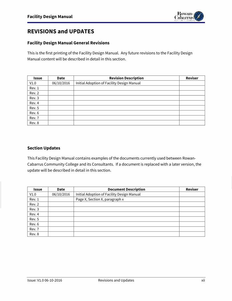
REVISIONS and UPDATES
Facility Design Manual General Revisions
This is the first printing of the Facility Design Manual. Any future revisions to the Facility Design
Manual content will be described in detail in this section.
Issue Date Revision Description Reviser
V1.0 06/10/2016 Initial Adoption of Facility Design Manual
Rev. 1
Rev. 2
Rev. 3
Rev. 4
Rev. 5
Rev. 6
Rev. 7
Rev. 8
Section Updates
This Facility Design Manual contains examples of the documents currently used between Rowan-
Cabarrus Community College and its Consultants. If a document is replaced with a later version, the
update will be described in detail in this section.
Issue Date Document Description Reviser
V1.0 06/10/2016 Initial Adoption of Facility Design Manual
Rev. 1 Page X, Section X, paragraph x
Rev. 2
Rev. 3
Rev. 4
Rev. 5
Rev. 6
Rev. 7
Rev. 8
Facility Design Manual
Issue: February 29, 2016 Revisions and Updates 1
Revised:
1. POLICIES AND PROCEDURES
1.1 Administration This section outlines the administration requirements which are unique to capital projects at Rowan-
Cabarrus Community College. These requirements supplement the most current edition of the State
Construction Manual required by the North Carolina Department of Administration, State Construction
Office (SCO). Although Community Colleges are not required to follow SCO procedures on Informal
Projects (those under $500,000 in construction value), the College voluntarily follows Formal Project
(those over $500,000 in construction value) administrative requirements for all projects; however, the
Designer is not required to make submittals to SCO. The College fully supports and encourages minority
business participation in projects on the campus and the Designer should make sure that the latest
guidelines from the SCO are followed during the preparation of the documents for bidding.
1.1.1 Designer’s Relationship with the College
The Designer should understand that the College is the Owner and Client for the project, even
though planning and design for the College is a cooperative procedure involving many persons
within the College, the State Construction Office (SCO), and other reviewing agencies.
The planning procedures related to the design and construction of capital improvement projects
are outlined in Chapter 200 of the State Construction Manual. For Projects under $500,000, the
College has the authority to perform the duties and responsibilities of the Department of
Administration and the Director of the State Construction Office. For projects of this size (informal
Projects as described in this Manual), the College has the authority to require design and
construction to comply with all, or a portion of, these procedures and to waive any of these
requirements as it deems applicable.
1.1.2 Contact with the College
The Chief Officer of Facilities Services is the primary contact for all correspondence and transfer of
information during the initial design phases. After award of the construction contract, the point
of contact is transferred to the College’s Project Manager for the duration of the construction
process and final closeout. All documents and correspondence from the Designer shall include
the North Carolina Community College System Office Project Number and, for Formal Projects, the
State Construction Office ID number.
1.1.3 Design Contracts
Design Contracts or Letters of Agreement will be issued in accordance with the provisions set forth
in Chapter 100 of the State Construction Manual and shall be coordinated with the Chief Officer of
Facilities Services with the College. The State of North Carolina Standard Form of Agreement
between Owner and Designer shall be modified by Supplemental Terms and Conditions to include
the following provisions, as well as others deemed appropriate by the College.
1.1.3.1. All work upon which the design hinges shall be the responsibility of the
Designer, and shall be performed under contract to the Designer. This may include, but not
be limited to, boundary, topographic, soil, and HAZMAT surveys and testing. Existing
conditions of both site and buildings are addressed in more detail below.
Facility Design Manual
Issue: February 29, 2016 Revisions and Updates 2
Revised:
1.1.3.2. All designs, drawings, specifications, design calculations, notes, and other
works developed in the performance of this contract shall become the sole property of the
Owner and may be used on any other design or construction without additional
compensation to the Designer. The use of the design, including tracings and specifications,
by any person or entity, for the purpose other than the Project as set forth in the Agreement,
shall be at full risk of such person or entity and the Designer shall be relieved of any liability
whatsoever, including claims for personal injury, property damage, or death, as a result of
such other use.
1.1.3.3. During the Post Construction Phase, the Designer shall develop electronic
Record Drawings and Specifications in delineated/vector format to be submitted to the
Owner. Specifications shall be annotated to reflect the specific manufacturer, model, color,
etc. installed on the Project. Record Drawings will incorporate the Contractor’s “red lined”
As-Built Drawings and will include not only updated pages for each of the Construction
Drawings, but shall also incorporate Fire Protection, Fire Alarm, and other drawings
developed by the Contractor’s Team and submitted as part of the Submittal Process.
1.1.3.4. During the Programming/Advanced Planning Phase, the Designer shall
perform necessary site inspections and develop “As-Built” Drawings of existing conditions
from which all subsequent design efforts will be based. The Owner shall provide available
record drawings, surveys, soils reports, HAZMAT surveys, etc. The available Record
Drawings are not guaranteed to be an accurate representation of the Work in place and the
Designer will be required to field verify the observable existing conditions. Lack of available
Record Drawings, surveys, reports, etc., will not relieve the Designer of the obligation to seek
out information necessary for the complete design of the project. Before contracting for
additional services of outside consultants, obtain approval from the Owner. The Designer
will need approval from the College prior to destructive testing of hidden or concealed
conditions.
1.1.3.5. During the Construction Phase, The Designer shall administer the Change
Order Process very closely, maintaining focus on its obligation to always represent the
Owner’s interest. Although Change Orders may include groupings of subordinate changes,
each discreet change shall be identified in the change order breakdown with adequate
description to effectively analyze the cost and time impact. All Change Orders will identify
the reason, or cause, for the requested change. Allowable causes are:
1.1.3.5.1. Owner Directed Change of Scope
1.1.3.5.2. Code Official Directed Change
1.1.3.5.3. Designer Error
1.1.3.5.4. Designer Omission
1.1.3.5.5. Concealed or Unforeseen Condition
1.1.3.5.6. Value Engineering
1.1.3.6. During the Design Development Phase, the Designer shall develop photo
realistic renderings of each project and submit to the Owner for the Owner’s unrestricted
use. As a minimum, for new buildings and additions, or major renovations of existing
buildings, there shall be a rendering of the exterior of the building from the predominant
access point (the “front” of the building) from a perspective that could be reproduced with
actual photographs; or, for interior projects of significance, an interior rendering from the
Facility Design Manual
Issue: February 29, 2016 Revisions and Updates 3
Revised:
most impactful perspective. Projects of larger scope may include requirement for other
perspectives.
1.1.4 Project Delivery Schedule
The Designer shall prepare and submit a proposed Project Critical Path Gantt Chart Delivery
Schedule to the Division of Facilities Services for approval. This schedule shall be developed in a
version of Microsoft Project, acceptable to the Owner, with all linkages, dependencies, and
constraints active. This schedule shall be submitted in both paper (minimum 11” x 17”) and
delineated electronic format within twenty-one (21) calendar days of the date of the design
contract, and it shall incorporate the end-of-phase milestone dates stipulated in the design
contract. In addition, this schedule shall include:
1.1.4.1. The start dates and durations of each major phase of design, including
Programming, Schematic Design, Design Development, Construction Documents, and
Bidding.
1.1.4.2. The durations and completion dates of each design review period required to
maintain the project schedule. For typical projects, the normal review time by the College
is approximately two (2) weeks for Conceptual, Schematic, and Design Development
submittals and four (4) weeks for Construction Document reviews. State Construction
Office Design Review Periods for Formal Projects will follow their requirements for duration
and should be included as separate activities, but will be concurrent with College reviews.
1.1.4.3. The projected durations and completion dates of other project-related
activities, such as funding decisions, surveys, sub-surface investigations, and all regulatory
approvals, including zoning shall be included.
1.1.4.4. The estimated durations of the construction contract award process and the
construction period.
1.1.4.5. The estimated durations of construction, broken into phases, if that is
anticipated.
1.1.4.6. The Project Development Schedule shall be updated and resubmitted with
each end-of-phase submittal described in Section 1.3 Design Phases. The schedule shall be
updated and submitted with every design submittal and shall capture re-submittals, delays,
and actual durations of activities.
1.1.5 Site and Existing Conditions Information
Accuracy of site and existing conditions upon which any design is based shall be the responsibility
of the Designer. The College will, upon request, furnish existing information for new construction
or renovations, as well as, available record drawings for remodeling and renovation projects. The
College does not in any way warrant that this information is complete, accurate, or correct. The
Designer shall supplement this information with field surveys, measurements, and testing. The
Designer is responsible for the accuracy of all information shown on the resulting existing
conditions drawings prepared by the Designer.
1.1.5.1. The Designer shall develop “As-Built” drawings which capture the starting
conditions from which all subsequent design efforts are based. As a minimum, these “As-
Facility Design Manual
Issue: February 29, 2016 Revisions and Updates 4
Revised:
Builts” will include:
1.1.1.1.1. Cover Sheet
1.1.1.1.2. Code & Summary Sheet, with identified deficiencies from current or
triggered Code.
1.1.1.1.3. Life Safety Plan, with identified deficiencies from current or triggered
Code.
1.1.1.1.4. Site Utility Plan, including an assessment of the observable condition
of existing systems, with identified deficiencies from current or
triggered Code and College Standards.
1.1.1.1.5. Grading, Drainage, and Paving Plan, including an assessment of the
condition of existing drainage systems, paving and curbing, with
identified deficiencies from current or triggered Code and College
Standards.
1.1.1.1.6. Site Lighting Plan, including an assessment of the condition of existing
systems, with identified deficiencies from current or triggered Code
and College Lighting Standards. Site Lighting Plan to also include an
assessment of the photometric conditions.
1.1.1.1.7. Landscaping Plan with existing trees and plantings (size and species)
and an evaluation of their condition.
1.1.1.1.8. Architectural Floor Plans, with identified deficiencies from current or
triggered Code and College Standards.
1.1.1.1.9. Reflected Ceiling Plans, with identified deficiencies from College
Standards.
1.1.1.1.10. Roof Plans, including annotations from thermographic survey and
evaluation of fall protection, with identified deficiencies from College
Standards.
1.1.1.1.11. Structural Plans, with identified concerns (including seismic).
1.1.1.1.12. Electrical Power Plans with Panel Schedules, including age of panels
and annotations from thermographic survey of existing panels, with
identified deficiencies from College Standards.
1.1.1.1.13. Lighting Plans with Panel Schedules, including age of panels and
annotation of actual lighting levels and annotations from
thermographic survey of existing panels, with identified deficiencies
from College Standards.
1.1.1.1.14. Plumbing Plans with identified deficiencies from current or triggered
Code and College Standards.
1.1.1.1.15. Mechanical Plans with identified deficiencies from current or triggered
Code and College Standards.
Facility Design Manual
Issue: February 29, 2016 Revisions and Updates 5
Revised:
1.1.1.1.16. Fire Protection Plans with identified deficiencies from current or
triggered Code and College Standards.
1.1.5.2. Site Surveys: All new projects site plans shall be developed from a new
topographical map developed specifically for that project; not from “as built” information
or previous project grading plans. Accurate information is critical and special conditions
such as asbestos, lead paint, underground tanks shall be addressed. All surveys shall be
performed by a land surveyor licensed in the State of North Carolina.
1.1.5.3. Geotechnical Surveys: The Designer shall direct and provide subsurface
investigation judged necessary for the design of the project.
1.2 Project Reviews This section outlines the review procedure requirements which are unique to capital projects at Rowan-
Cabarrus Community College. These requirements supplement the most current edition of the State
Construction Manual required by the North Carolina Department of Administration, State Construction
Office (SCO).
1.2.1 Initial Planning Conference
An initial planning conference will be scheduled by the Division of Facilities Services to include
representatives of the stakeholding departments and other appropriate participants to discuss
general requirements of the program and procedures for facilitating the Designer’s work. This
conference should also include discussion of the College’s Goals/Expectations for Sustainable
Design. This conference will be held as soon as possible after selection of a Designer for the project.
It is recommended that the Designer’s professional consultants for plumbing, HVAC, electrical, and
telecommunications design attend this conference.
1.2.2 Design Reviews
The Designer is required to make submittals and presentations, and to participate in review
conferences at various stages of the project design process. It is recommended to the Designer
that the number of reviews required for the project be determined prior to executing a form of
agreement.
The Designer will be expected to record the content of all conferences and, within seven days, to
provide meeting minutes containing a complete summary of the decisions and actions which
affect the project. The Designer will issue these meeting minutes to all meeting participants and
other interested parties for the Project.
1.2.2.1. Presentation and Review Conferences: During the design process, the Designer
will be expected to make presentations to various groups who must review and approve the
proposed project designs. These groups might include stakeholding divisions and
departments, other Consultants to the College, the President, the Board of Trustees (BOT)
and Student, Faculty and Staff Associations. All conferences and presentations will be
scheduled by, or with approval of, the Division of Facilities Services.
1.2.2.2. Schematic Design Conference: Normally, several conferences precede the
approval of the architectural program and, subsequently, the Schematic Design
documents. Conferences may be required to clarify the program requirements, to review
Facility Design Manual
Issue: February 29, 2016 Revisions and Updates 6
Revised:
and discuss the Designer’s design proposals, to discuss the Designer’s evaluation of the
achievability of the program requirements within budget constraints, and to assist in the
definition of alternates which will become an important component of the Construction
Documents.
1.2.2.3. Presentations to the College Administration & Board of Trustees: The Designer
will be expected to make presentations of the project design to appropriate RCCC Divisions
and Departments, the President, and to the Board of Trustees, as necessary. The following
exhibits are typically required for these presentations: floor plans, exterior elevations, and
renderings, as necessary, to communicate the extent of design. When required, these
presentations may be scheduled to occur as early as possible in the Design Development
Phase of the project.
1.2.2.4. End-of-Phase Reviews: At least one conference in each phase will be devoted
to the end-of-phase review of the Design Development and Construction Documents, and
will be for the purpose of discussing any areas of concern that arise during the review
process. The Designer and the Designer’s primary consultants will be expected to attend
these review conferences. It should be noted that the College reviews projects to ensure
that they are developed in conformance with its criteria and that they will be suitable for
College purposes, but does not provide a checking or quality control service for the
Designer.
1.2.3 Agency Reviews
The Designer shall assist the Owner in acquiring all required permits. The Designer is to take the
lead role in determining and advising the Owner of the required permits, through consulting with
the various permit agencies through pre-application meetings to document both applicability and
specific permitting criteria. The Architect is to prepare the applications for Owner’s signature,
along with all supporting documents, transmit permitting agency invoices of fees to the Owner for
payment, submit the application(s) on behalf of the Owner and respond to any agency inquiries.
See Chapter 200 of the State Construction Manual for additional information. The Designer will
work with the Division of Facilities Services to coordinate each submittal to the governing
organization, which may include, but not be limited to, the following:
1.2.3.1. The local county and/or city having jurisdiction
1.2.3.2. State Construction Office (SCO)
1.2.3.3. North Carolina Department of Environmental and Natural Resources
(NCDENR)
1.2.3.4. North Carolina Department of Transportation (NCDOT)
1.2.3.5. County and/or State Department of Health
Approaching completion of the project, the Architect is to prepare and submit Certificates of
Completion, coordinate permitting agency inspections, and assure that clearance letters are
received prior to the placement of new systems into service, and prior to Certificate of Substantial
Completion.
Facility Design Manual
Issue: February 29, 2016 Revisions and Updates 7
Revised:
1.2.4 College Reviews
In addition to the various State and local agencies reviews required for the project, design
submittals may also be reviewed by various stakeholding divisions and departments (user groups)
within the College. The Division of Facilities Services will coordinate the End-of-Phase Reviews
outlined in Item 1.2.2. The Designer shall not proceed to the next phase before receiving written
approval of the previous phase from the Chief Officer, Facilities Services.
1.3 Design Phases
This section outlines the design phase requirements which are unique to capital projects at Rowan-
Cabarrus Community College. These requirements supplement the most current edition of the State
Construction Manual required by the North Carolina Department of Administration, State Construction
Office (SCO).
The Guidelines are developed based on two project types which include:
Design Phases for Formal Projects (over $500,000 in constructed value)
Design Phases for Informal Projects (under $500,000 in constructed value)
1.3.1 Formal Projects
1.3.1.1 General - The Designer shall comply with Chapter 300 of the State
Construction Manual regarding design phases and submittal requirements. At the
beginning of the Design Phase, the Designer will meet with the Capital Projects
Coordinator to establish an aggressive project delivery schedule and confirm which
stakeholder group(s) will be involved in the project. Primary contacts shall be established
to ensure the Designer receives the necessary information and approvals in a timely
manner. The design phases outlined below describe supplementary requirements of the
College for a “typical” project process.
1.3.1.2 Programming / Advance Planning - The Designer shall facilitate an integrated
design approach utilizing the designated representatives of the College and user group(s)
to establish the design criteria for the project. The Designer shall define the program,
space needs, site considerations, and project budget in this phase. The Designer shall
comply with the College’s Standards for space planning and furniture. At completion of
this phase of the project, the Designer will summarize all programmatic and advance
planning criteria in written format to include the following Programming/Advance
Planning Submittals:
1.3.1.2.1 Project Budget
1.3.1.2.2 Site Analysis
1.3.1.2.3 Sustainable Design Criteria
1.3.1.2.4 Detailed Space Program
1.3.1.2.5 Classroom Occupancy and Office Counts
1.3.1.2.6 Code Summary
1.3.1.2.7 Project Delivery Schedule
1.3.1.2.8 Special Requirements
1.3.1.2.9 “As-Built” Drawings (on Remodel/Renovation Projects).
1.3.1.3 Schematic Design - Prior to the beginning of the Schematic Design Phase, the
Designer shall finalize the program, budget, and project scope with the designated user
Facility Design Manual
Issue: February 29, 2016 Revisions and Updates 8
Revised:
group(s) and the College’s Project Manager. A written summary shall be provided to the
Division of Facilities Services. Based on an approved summary of the project
requirements, the Designer shall prepare a Schematic Design package illustrating the
recommended implementation of the program and project requirements. The Designer is
expected to involve the Division of Facilities Services, the stakeholding
division/departments, and appropriate tenant groups within the College (and, possibly,
the community) during the development of the schematic design. A number of studies
may be required to satisfactorily explore the range of alternatives possible. Schematic
Design Submittals: In addition to those copies required by the various State agencies, the
Schematic Design Phase Submittal to the College shall consist of one (1) hard copy and
one (1) electronic copy of the following documents:
1.3.1.3.1 A general description of the project indicating the construction
materials, structural systems, and mechanical, electrical, and plumbing systems.
1.3.1.3.2 A line rendering of the project showing proposed massing,
fenestration, and roof type.
1.3.1.3.3 A site plan showing the size of the facility, adjacent buildings,
generalized topography, roads, walks, and utility service.
1.3.1.3.4 Floor plans for all affected floor levels, including mechanical,
electrical, and telephone/IT rooms and service areas. Identify each room or space
by functional name, room number following the College’s Room Numbering
Scheme (integrating into existing Building Numbering Scheme on minor
renovations/ remodels), rough square footage, and functional occupancy.
1.3.1.3.5 A Security Plan showing concept for incorporating Crime Prevention
Through Environmental Design (CPTED) Principles and identifying all elements of
the Security Concept for the building, including Video Surveillance, Access
Controlled Doors, Emergency Phones, and Mass Notification.
1.3.1.3.6 A Responsibility Matrix identifying Contractor, Owner, or other Third
Party responsibility for performing any element of the work required to provide a
fully functioning building or space. This includes furnishing and installing
Furniture, Fixtures and Equipment.
1.3.1.3.7 A tabulation of the floor areas.
1.3.1.3.8 A statement of probable construction cost. (Estimates shall include
separate items for site work, utility extensions, and other items outside the
structure.) Show estimated cost per square foot. Indicate new construction costs
and/or remodeling costs, including major and minor areas of remodeling, with
approximate areas.
1.3.1.3.9 An updated Project Delivery Schedule.
Facility Design Manual
Issue: February 29, 2016 Revisions and Updates 9
Revised:
1.3.1.3.10 An updated Sustainable Design Criteria.
1.3.1.3.11 Annotated written response to all previously received review
comments either indicating that they are incorporated or justifying their proposed
rejection.
1.3.1.3.12 Building modelling and administrative work necessary to submit the
project to Duke Energy for consideration in the Smart Energy Advantage incentive
program.
1.3.1.4 Design Development - Prior to proceeding to the Design Development Phase,
the Designer shall obtain written approval from the Division of Facilities Services and SCO
on the Schematic Design submittal. The Designer shall prepare the Design Development
documents which set forth in detail all of the basic elements, systems, and materials to be
used in the project. During the Design Development process, the Designer is expected to
involve the Director of Design & Construction and, through his representative, the
department user group(s), and appropriate members of the College. A number of studies
may be required to satisfactorily explore the range of alternatives possible; for example, two
or more structural, electrical, and mechanical systems that are feasible for the project shall
be evaluated and the Designer shall select the systems that are best suited to the project. In
addition to those copies required by the various State agencies, the Design Development
Phase Submittal to the College shall consist of one (1) hard copy and one (1) electronic copy
of the following documents:
1.3.1.4.1 Site drawing(s) showing adjacent buildings, significant existing
features, proposed limits of construction, proposed site improvements, existing
and proposed contours, horizontal and vertical control points, general elements of
drainage and sedimentation control, utility requirements, established easements,
and other site data furnished on the previous submittal.
1.3.1.4.2 An update to the exterior rendering of the project, including textures,
as well as renderings of significant interior spaces.
1.3.1.4.3 Scaled architectural plans of all floor levels. Identify each room or
space by name and number.
1.3.1.4.4 Elevation drawings of every exterior side of each structure showing
materials, features, openings, floor and roof lines, grade lines, footings, and
everything exposed to view above eaves or parapets.
1.3.1.4.5 Section(s) through the entire building, selected to best show the
relationships of architectural and engineering features.
1.3.1.4.6 A Room Finish Schedule showing the type of material to be used for
floors, walls, and ceilings.
1.3.1.4.7 Equipment and furniture layouts for all rooms, when crucial in
indicating the adequacy of the arrangement and configuration of such rooms.
Facility Design Manual
Issue: February 29, 2016 Revisions and Updates 10
Revised:
1.3.1.4.8 The structural system design, including boring logs from the
subsurface investigation report; the allowable soil bearing pressure; a foundation
plan showing the basic elements of the foundation system; typical floor framing
plan showing size, spacing, and type of principal members; a roof framing plan;
and, the locations of shear walls and/or bracing, with such additional information
as may be necessary to describe the method of lateral load resistance. Structural
drawings shall show the design floor loadings of all areas.
1.3.1.4.9 The plumbing design showing the general development of the
plumbing system, including source of supply and disposal of waste.
1.3.1.4.10 The mechanical design showing the basic layout and location of HVAC
equipment, piping, and duct-work; a schematic of the temperature control
systems; diagrams of air, hot water, and/or steam systems, chilled water and
condenser water systems; and, major design calculations.
1.3.1.4.11 The electrical system design showing an analysis of loads and the
major design calculations; the basic fixtures and equipment; and, location of the
electrical power distribution components, including primary service circuits,
transformers, main switch-gear, motor control centers, power and branch circuits
panels, lighting, and switching patterns.
1.3.1.4.12 Single line drawings showing the basic elements of the fire alarm,
smoke/heat detection, telecommunications (telephone and data), Campus closed
circuit TV, emergency lighting, paging, or other systems in the project.
1.3.1.4.13 An outline specification, indicating materials, types of construction,
and equipment to be used. Include a description of each plumbing, HVAC, fire
protection, telecommunications, and electrical system design concept. Include
elevator characteristics and the names of proposed manufacturers and cut sheets
of ‘major’ HVAC, plumbing, fire protection, special systems, data, electrical
equipment, and fixed equipment.
1.3.1.4.14 The reports of the required Life Cycle Cost & Energy Consumption
analysis.
1.3.1.4.15 A tabulation of building data, including square feet of floor area, roof
deck “U” factor, heating load in BTUH, air conditioning in tons, plumbing load in
drainage fixture units, water demand in peak GPM, electrical loads in KVA, the
design live loads, and number of occupants.
1.3.1.4.16 A statement of probable construction cost using, as a minimum, the
requirements expressed in appropriate units, such as area, volume, linear feet,
tons, BTUH, KW requirements, etc., taking into consideration the actual systems
and materials proposed in the submittal. Site work, utility services, and other
items outside of the structure shall be as shown as separate items. A complete
tabulation showing the breakdown of appropriated and/or authorized funds shall
Facility Design Manual
Issue: February 29, 2016 Revisions and Updates 11
Revised:
be included.
1.3.1.4.17 Updated Project Delivery Schedule
1.3.1.4.18 Updated Sustainable Design Criteria
1.3.1.4.19 Annotated written response to all previously received review
comments either indicating that they are incorporated or justifying their proposed
rejection.
1.3.1.4.20 Develop and submit application for Duke Energy Smart Energy
Advantage incentive program.
1.3.1.4.21 For projects involving occupied spaces, provide narrative of impact
on occupied spaces.
1.3.1.4.22 Phasing Plan(s) for projects that require several phases to complete.
1.3.1.5 Construction Documents - Prior to proceeding to the Construction Documents
Phase, the Designer shall obtain written approval from the Division of Facilities Services and
SCO. Based upon the approved Design Development submittal, the Designer shall prepare
the Construction Documents and other materials required for the receipt of competitive
bids on the project. These documents shall be prepared in compliance with the
requirements outlined in the State Construction Manual. In addition to those copies
required by the various State agencies, the Design Development Phase Submittal to the
College shall consist of one (1) hard copy and one (1) electronic copy of the following
documents:
1.3.1.5.1 Drawings and specifications as outlined in the State Construction
Manual.
1.3.1.5.2 The Cover Sheet of the Construction Drawings shall include the
following summary:
1.3.1.5.2.1 Floor area (square feet) tabulation
1.3.1.5.2.2 Volume of floor area (cubic feet) tabulation
1.3.1.5.2.3 Roof system “U” factor
1.3.1.5.2.4 Maximum steam demand tabulation
1.3.1.5.2.5 Heating load in BTUH
1.3.1.5.2.6 Air conditioning in tons
1.3.1.5.2.7 Plumbing load in drainage fixture units
1.3.1.5.2.8 Water demand in peak GPM
1.3.1.5.2.9 Electrical loads in KVA
1.3.1.5.2.10 Structural design live loads
1.3.1.5.2.11 Occupancy load summary
1.3.1.5.3 Where interior or exterior colors, materials, or finishes are specified, a
“color board” (one copy only) shall be provided, accurately depicting the materials,
colors, and finishes to be used on the project and indicating their location(s) within
Facility Design Manual
Issue: February 29, 2016 Revisions and Updates 12
Revised:
the project.
1.3.1.5.4 A list of “Owner Preferred Alternates” should be clearly defined in the
submittal.
1.3.1.5.5 Updated Project Delivery Schedule.
1.3.1.5.6 Provide one set of AutoCAD files and 11” x 17” drawings to the Director
of Facilities Operations & Maintenance showing the architectural floor plan(s) with
final approved room numbers as they will appear at the entrance of each space.
1.3.1.5.7 Provide one set of AutoCAD files showing the site plan, exterior
elevations and roof plan. This drawing information will be used to update the
Campus Map and for planning purposes.
1.3.1.5.8 Updated Sustainable Design Criteria
1.3.1.5.9 Annotated written response to all previously received review
comments either indicating that they are incorporated or justifying their proposed
rejection.
1.3.1.5.10 Develop and submit application for Duke Energy Smart Energy
Advantage incentive program.
1.3.1.5.11 For projects involving occupied spaces, provide narrative of impact
on occupied spaces.
1.3.1.5.12 Phasing Plan(s) for projects that require several phases to complete.
After the initial submittal of completed Construction Documents, the Designer shall revise the
Construction Documents in accordance with review comments. The Designer shall prepare a
written response to the College’s comments and submit to the Division of Facilities Services within
three (3) weeks of receipt of the review comments.
1.3.2 Informal Projects
1.3.2.1 General – The Designer shall comply with Chapter 300 of the North Carolina
State Construction Manual regarding design phases and submittal requirements. The items
outlined below describe supplementary requirements of the College for a process based on
the anticipated project cost being less than $500,000. These items may vary per project.
1.3.2.2 Programming - The criteria outlined in Item 1.3.1.2 of this Manual are
applicable. If necessary, a review by the Division of Facilities Services will be performed to
assure that the user’s needs are being met for the project.
1.3.2.3 Design - The criteria outlined in Items 1.3.1.3, 1.3.1.4, and 1.3.1.5 of this Manual
are applicable for Informal Projects. The College will work with the Designer to consistently
seek ways in which to improve the design/review process for Informal Projects. The
Designer is responsible for obtaining review comments and agency approvals in accordance
Facility Design Manual
Issue: February 29, 2016 Revisions and Updates 13
Revised:
with the State Construction Manual. The Division of Facilities Services will review plans and
specifications for usability, maintenance, and compatibility with existing conditions. The
College is not expected to perform a complete technical review. The Designer will be
expected to produce a technically accurate set of plans and specifications that shall be bid
without alteration by the College. At the beginning of the Design Phase, the Designer will
meet with the Capital Projects Coordinator to establish an aggressive project delivery
schedule and confirm which stakeholder group(s) will be involved in the project. Primary
contacts shall be established to ensure the Designer receives the necessary information and
approvals in a timely manner. Review times by the College should be kept to a minimum in
an effort to maintain the project delivery schedule. The number of submittals required by
the project shall be determined with the Designer, prior to final negotiation of the design
contract or letter agreement. Submittal options may include:
1.3.2.3.1 Combine Schematic Design and Design Development submittal; or,
1.3.2.3.2 Eliminate all but Construction Document review with sit-down review
at 50% completion; or,
1.3.2.3.3 Some projects may only require a Construction Document review.
1.4 Bidding This section outlines the bidding requirements which are unique to capital projects at Rowan-Cabarrus
Community College. These requirements supplement the most current edition of the State Construction
Manual required by the North Carolina Department of Administration, State Construction Office (SCO).
Prior to proceeding to the Bidding Phase, the Designer shall obtain written approval from the Division of
Facilities Services and the SCO.
The Designer shall comply with Chapter 400 of the State Construction Manual and applicable North
Carolina General Statutes regarding bidding phase and submittal requirements. For projects not
requiring submission to SCO, Formal Projects and Informal Projects (with their associated dollar values)
are as defined in this Manual.
Although it is desired by the College to maximize competition in the bidding process, the College
recognizes the necessity of ensuring only contractors capable of adequately performing are contracted
to perform construction at the College. The Designer shall develop Bidding Requirements which ensure
that only firms with adequate relevant experience, staff, and financial stability are considered for award.
As a minimum, the following must be ascertained during the review of bid packages:
Organizational, individual staff and proposed subcontractor experience on projects of similar
size, scope, and complexity.
Organizational, individual staff and proposed subcontractor certifications and qualifications in
particular specialties deemed necessary.
On Formal Projects, experience on projects constructed under State Construction Office’s
purview.
Former clients have been satisfied with the Contractor’s performance on similar projects.
Include contact information for referenced former clients.
Facility Design Manual
Issue: February 29, 2016 Revisions and Updates 14
Revised:
Satisfactory performance on previous State Construction Office administered projects, as
documented with SCO.
Bidders who do not adequately meet the requirements set forth in the Pre-Qualification or Bidding
Requirements must be deemed “unresponsive”.
The Designer shall coordinate all activities and information through the bidding process with the
College’s Project Manager.
The date for receipt of bids shall be established by the Designer in consultation with the College and the
SCO. A period of four (4) weeks is the typical duration between the publication of the Advertisement for
Bids and the receipt of bids.
Bid Document Submittals: The Bid Document Submittal to the College shall consist of one (1) hard copy.
These sets shall be in the possession of the Chief Officer of Facilities Services during bidding.
At the College’s discretion, a Bid Bond shall be included with all Bids; Designer to note specific
requirements in the Bid Documents.
1.5 Construction Administration This section outlines the construction administration requirements which are unique to capital projects
at Rowan-Cabarrus Community College. These requirements supplement the most current edition of the
State Construction Manual required by the North Carolina Department of Administration, State
Construction Office (SCO).
Prior to proceeding to the Construction Administration Phase, the Designer shall obtain written
approval from the Division of Facilities Services and SCO.
The Designer shall comply with Chapter 500 of the State Construction Manual regarding the
construction phase and submittal requirements.
The Designer shall coordinate all activities and information through the construction phase with the
College’s Project Manager.
The Construction Phase will begin with the Designer’s receipt of the fully executed copy of the
construction contract(s).
1.5.1 Pre-Construction Conference
The Designer, in consultation with the College’s Project Manager and the State Construction
Office, shall arrange for a Pre-Construction Conference. The purpose of this meeting is to review
the requirements of the project and to provide a framework for the coordination of all construction
activities. Required Attendees: College PM/CM, Designer, Designer’s Consultants, General
Contractor, all Major Sub-Contractors, Vendors providing service to the College for the project (i.e.
A-V Vendor, IT Equipment, Furniture, etc.), and additional parties as appropriate for the scope of
the work.
The Designer shall send copies of the minutes of this conference to all attending contractors, the
Facility Design Manual
Issue: February 29, 2016 Revisions and Updates 15
Revised:
College’s Project Manager, the Chief of Facilities Services, the State Construction Office, and any
other interested parties.
1.5.2 Notice to Proceed
Upon approval of all regulatory agencies, the Designer will coordinate with the SCO and the
College’s Construction Manager a date for each contract to proceed with Work. The Designer will
then issue a “Notice to Proceed” according to the type of construction contract for the project.
These letters shall establish the start date, duration, and completion date for the overall project,
and for any discrete phases. Copies of each letter issued by the Designer shall be forwarded to the
SCO and Division of Facilities Services.
1.5.3 Field Inspections
The Designer shall provide necessary liaison and, as a minimum, weekly site visits to the project
to determine compliance with plans and specifications. All site visits will be documented with
Field Reports, with photos documenting progress and issues of concern, which shall be distributed
to the project team and others as requested by the Owner.
The RCCC Division of Facilities Operations and Maintenance staff will also observe work progress
periodically and will provide comments to the Designer through the College’s Project Manager.
Included among these observations by the Physical Plant will be an above-the-ceiling inspection
of all areas, before suspended ceilings are installed.
1.5.4 Progress Meetings
The Designer shall establish a schedule of progress meetings at the job site in accordance with
Chapter 500 of the State Construction Manual. The frequency of meetings will have been set in the
special conditions of the contract and may be revised by the College, depending on progress and
nature of the work. Minutes of the meetings will be kept by the Designer and distributed to all
parties.
1.5.5 Administration
The Designer shall provide other construction phase services for the project, including:
1.5.5.1 Prepare written weekly site inspection Field Reports.
1.5.5.2 Prepare written monthly construction progress reports, with copies of the
weekly reports attached.
1.5.5.3 Review shop drawing submittals. The Designer shall provide the College
Project Manager with an electronic copy of each approved submittal.
1.5.5.4 Provide general administration of the construction contract.
1.5.5.5 Review results of all field testing on the project and advise the Owner and
Contractor of non-compliance.
1.5.5.6 Respond promptly to all Requests for Information (RFIs).
1.5.5.7 Review requested change orders from the Contractor and advise the Owner.
Facility Design Manual
Issue: February 29, 2016 Revisions and Updates 16
Revised:
1.5.5.8 Conduct final inspections and review of punch list.
1.5.5.9 Review and certify contractor applications for payment.
1.5.6 Special Scheduling and Construction Constraints
The culture of “Students First” must be effectively communicated to the Contractor along with the
understanding that any inconvenience to the students, faculty, and/or staff of the College must be
mitigated to the greatest extent possible, planned in advance, and communicated broadly. This
is particularly important when projects involve spaces in, or contiguous to, congested areas of the
campus, or other critical activities. Special steps may be required to avoid or minimize interference
with on-going campus operations. The Designer and Contractor(s) should determine those areas
where impact is critical or cannot be avoided. Dealing with utility outages is the most common
consideration, while the problems of noise, vibration, dust, and circulation must also be explored.
1.5.6.1 Phasing: The Designer will work with the Owner to understand, capture, and
convey to the Contractor the constraints which will require phasing of a project. Because of
the cost implications of phasing any project, this impact to the project schedule must be
clearly described by the Designer in developing the Construction Documents so that the
implications of the phases are understood by all bidders on bid day.
1.5.6.2 College Schedule: Break periods should be captured in the initial Project
Delivery Schedule as they not only impact the design of the project (employees of the
College do not work during Winter and Spring Breaks), but also the construction (break
periods often allow unfettered access to buildings). Conversely, the First Week of Classes
and Finals Week will limit Designer and Contractor access to educational spaces and other
areas of the campuses.
1.6 Final Closeout This section outlines the final closeout requirements which are unique to capital projects at Rowan-
Cabarrus Community College. These requirements supplement the most current edition of the State
Construction Manual required by the North Carolina Department of Administration, State Construction
Office (SCO).
The Designer shall comply with Chapter 600 of the State Construction Manual regarding the final report
and closeout requirements. The Designer shall provide the following project close-out services upon
completion of the project:
1.6.1 Assemble and forward all Final Report Documents for review by the Division of
Facilities Services.
1.6.2 Prepare a written description of the HVAC system and operational requirements. The
Designer shall also schedule and conduct a review of the HVAC plans and specifications with the
Physical Plant personnel.
1.6.3 Provide copies of all Operations and Maintenance manuals to be supplied by the
General Contractor or Project Manager.
Facility Design Manual
Issue: February 29, 2016 Revisions and Updates 17
Revised:
1.6.4 Provide a List of Equipment for Planned Maintenance, listing the equipment, systems
and elements to be added to the College’s electronic maintenance management program. This
listing will include a matrix of all manufacturer recommended planned maintenance.
1.6.5 Provide the results of the fire alarm tests and invite a representative of fire alarm
contractor to the final inspection with the Department of Insurance. The Designer shall
coordinate the delivery of as-built drawings of the fire alarm system and spare parts (6% of
installed stand-alone smoke/heat detectors) to be handed over to the College within 30 days of
the final inspection.
1.6.6 Submit close-out documents to Duke Energy Smart Energy Advantage incentive
program and track final acceptance and delivery of incentive reimbursement.
1.6.7 Computation and disposition of liquidated damages (if required).
1.6.8 Issue the Certificate of Final Completion & Compliance.
1.6.9 Provide record drawings and specifications within 30 days of substantial completion
(or 15 days after receiving Contractor’s field mark-ups, whichever is later) in accordance with the
requirements outlined in Chapter 600 of the State Construction Manual. The digital format shall
be compatible with the College’s computing environment.
1.6.10 Provide an electronic copy of the Final Report in accordance with the requirements
outlined in Chapter 600 of the State Construction Manual.
Facility Design Manual
Issue: February 29, 2016 Revisions and Updates 18
Revised:
2. DESIGN GUIDELINES
2.1. Introduction The purpose of the Design Guidelines section is to convey guidance for planning, design and construction
at Rowan-Cabarrus Community College. The guidelines offer direction for aesthetics and general design
intent. The Designer should reference Section 3 – College Standards for detailed requirements.
Rowan-Cabarrus Community College strives to protect the history and traditions of the communities in
which our campuses and centers are located. These guidelines are intended to allow and encourage
each campus to continue to evolve in such a way that every building contributes in a unique way to the
context of the campus, while being respectful of its natural surroundings.
The Campus Master Plan is the official document for continued growth and new development at Rowan-
Cabarrus Community College. It is expected that the Designer shall adhere to the design intent of the
Master Plan and Guiding Principles.
No written guidelines can fully describe in detail all aspects of the required design criteria. These
guidelines seek to portray a prescriptive approach for defining the parameters of a project and design
outcome. For design and construction of new facilities (or renovation of existing buildings), the Designer
should carefully consider the following parameters for each new project at the College:
Responsive to use
Sustainable
Flexible
Technologically advanced
Responsive to topography
Pedestrian oriented
Exhibits detail
Expresses physical harmony
A 100-year solution
Model for learning
2.2. General Considerations In addition to the parameters defined in the previous paragraphs, the College has defined several general
considerations the Designer should address and/or integrate into each new project: design within
available funds, energy conservation, and materials conservation.
2.2.1 Design within Available Funds
Designers are directed and required to base their designs upon the budgeted funds available. The
Designer shall continually monitor program requirements and cost estimates to assure that the
project is designed within the available funds and does not deviate from the quality standards
established herein. If at any time, the Designer believes that satisfying the stated program
requirements, at the level of quality desired, will exceed the budgeted funds available, he or she
must inform the Division of Facilities Services without delay.
Facility Design Manual
Issue: February 29, 2016 Revisions and Updates 19
Revised:
2.2.2 Energy and Materials Conservation
The College is dedicated to the principle of conserving materials and energy. College personnel
will examine proposed construction for means of reducing, not only the initial cost of energy and
non-renewable resources, but also long-range operating costs. In addition to basic conservation
requirements, the Designer should consider the utilization of passive solar energy techniques,
non-conventional and renewable energy resources, recycled materials content of specified
materials, and non-conventional materials.
2.2.3 Sustainable Design
The College shall uphold a sustainable doctrine by incorporation of new technologies for existing
and future facilities, by providing efficiencies in energy, economic, and environmental
performance that are substantially better than conventional practice, as a model for the state and
region. All new campus construction will be built to at least the U.S. Green Building Council’s
(USGBC) LEED Silver Standard, or equivalent. The College will determine whether or not the
project is to be certified with USGBC or any other sustainability certification organization.
2.2.3.1 Low-Impact Development (LID): New development on campus shall follow the
guidelines for Low Impact Development (LID) by utilizing innovative storm water
management techniques. Low Impact Development (LID) is an approach to land
development that can be utilized at RCCC as the campuses continue to grow and that works
with nature to manage stormwater as close to its source as possible. LID employs principles
such as preserving and recreating natural landscape features, minimizing effective
imperviousness to create functional and appealing site drainage that treats stormwater as
a resource rather than as a waste product. By implementing LID principles and practices
throughout the campus environment, water can be managed in a way that reduces the
impact of built areas and promotes the natural movement of water within an ecosystem or
watershed. Applied on a broad scale, LID can maintain or restore a watershed’s hydrologic
and ecological functions, creating a better environment for the Rowan and Cabarrus County
communities. There are many practices that have been used to adhere to these principles,
such as:
2.2.3.1.1 Stormwater Wetlands These temporarily store rain runoff in shallow
pools that support conditions suitable for the growth of wetland plants. These
constructed wetland systems, which can be utilized as development occurs on
campus, are designed to maximize the removal of pollutants from stormwater
runoff via several mechanisms: microbial breakdown of pollutants, plant uptake,
retention, settling, and absorption. These structural practices are similar to wet
ponds, but incorporate wetland plants, strategically placed stone to encourage
growth of various wetlands species, and irregular shorelines to break up linear flow
of stormwater. These accommodations mimic a natural pond or wetland with the
affect that, as stormwater flows through the wetland, pollutant removal is
achieved by settling and biological uptake.
2.2.3.1.2 Bioswales: These are landscape elements designed to remove silt and
pollution from surface runoff water. They consist of a swaled drainage course with
gently sloped sides and are filled with vegetation, compost, and/or riprap. The
Facility Design Manual
Issue: February 29, 2016 Revisions and Updates 20
Revised:
water’s flow path, along with the wide and shallow ditch, is designed to maximize
the time water spends in the swale, which aids the trapping of pollutants and silt.
A simple application on campus could be around parking lots, where substantial
automotive pollution is collected by the paving and then flushed by rain. The
bioswale wraps around the parking lot and treats the runoff before releasing it to
the watershed or storm sewer.
2.2.3.1.3 Riparian Buffers: These are vegetated areas, near a stream or pond,
which help shade and partially protect a body of water from the impact of adjacent
land uses. They play a key role in increasing water quality in associated streams,
rivers, and lakes, thus providing environmental benefits. These buffers are
important natural biofilters, protecting aquatic environments from excessive
sedimentation, polluted surface runoff, and erosion. They supply shelter and food
for many aquatic animals and shade that is an important part of aquatic
environment temperature regulation. With development comes the decline of
many aquatic ecosystems. Riparian buffers can become a conservation choice
aimed at increasing water quality and lessening pollution of RCCC”s water sources.
2.2.3.1.4 Cisterns: These are receptacles constructed to catch and store
rainwater for later use. Promoting the use of cisterns can provide an alternative
source for irrigation, reducing the demand on local water sources within the
campus area. To conserve groundwater, rainwater can be collected, stored, and
used for such things as watering gardens, washing cars, or other non-potable water
needs throughout the RCCC campus.
2.2.3.1.5 Permeable Pavements: These can be utilized throughout the campus
for roads, parking lots, and walkways to allow the movement of water and air
around the paving material. These paving surfaces keep the pollutants in place in
the soil and allow water seepage to groundwater recharge while preventing stream
erosion problems. They capture heavy metals that fall on them, preventing the
heavy metals from washing downstream and accumulating inadvertently in the
environment. Porous pavement also gives campus trees the rooting space they
need to grow to full size. This integrates healthy ecology and the thriving RCCC
campus with the living tree canopy above, the campus traffic on the ground, and
living tree roots below.
2.2.3.1.6 Green roofs: These are roofs of buildings that are partially, or
completely, covered with vegetation and soil, or a growing medium, planted over
a waterproofing membrane. Numerous benefits can result from the adoption of
green roof technologies: the recovery of green space, moderation of the urban heat
island effect, improved stormwater management, water and air purification, and a
reduction in energy consumption. The mitigation of stormwater runoff can be a
great benefit to RCCC because of the prevalence of impervious surfaces in the
campus area. A major benefit of green roofs is their ability to absorb stormwater
and release it slowly.
2.2.3.1.7 Planted Filtering Strips: These are land areas situated between a
Facility Design Manual
Issue: February 29, 2016 Revisions and Updates 21
Revised:
potential pollutant source area and a stream or pond that receives runoff. A
planted filter strip provides water quality protection by reducing the amount of
pollutants before the runoff enters the surface water body. Filter strips also
provide localized erosion protection since the vegetation covers an area of soil that
otherwise might have a high erosion potential.
2.2.3.2 Water Conservation: The College will strive to prove itself a leader in water
management over time by enforcing the integration of water conservation practices
throughout the campus. All evidence points to increasingly stressed water supplies in North
Carolina and throughout the Southeast. Additionally, trends suggest that water
management will be more heavily regulated in the future. By beginning to address these
eventualities now, the campus will prove itself a leader in water management. Reduce
freshwater use 40% by implementing technology to enable water capture and reuse as part
of the building design.
2.2.3.2.1 Reduce stormwater runoff impacts by implementing at least one Low
Impact Development technology as described above.
2.2.3.2.2 Protect surface water by preventing culverts on any currently daylit
surface water. Existing surface water enclosed in culverts will be daylit to the
extent practical.
2.2.3.2.3 Utilize permeable surfaces as much as possible.
2.2.3.2.4 Select drought resistant plantings.
2.2.3.3 Energy Efficiency: The College will strive to reduce its carbon footprint over
time by enforcing the integration of energy efficient practices throughout the campus.
Whether it be for global concerns of climate change or national concerns of energy
independence, the College can have a significant impact on the consumption of energy
through subtle and inexpensive changes to conventional design. All new construction on
campus shall be designed in an energy efficient manner that complements the overall
design intent and reduces total building energy consumption by addressing the following
requirements:
2.2.3.3.1 Design site, building envelope, and systems and equipment in
compliance with ANSI/ASHRAE/IES/USGBC Standard 189.1-2014 Standard for the
Design of High Performance Green Buildings.
2.2.3.3.2 Reduce overall building energy loads.
2.2.3.3.3 Optimize the use of natural daylighting in lieu of electrical lighting.
Where impractical, utilize the highest efficiency electrical lighting source.
2.2.3.3.4 Utilize occupancy sensor controls.
2.2.3.3.5 Incorporate exterior shading devices or extended roof overhangs to
control heat gain, particularly on southern and western exposures.
Facility Design Manual
Issue: February 29, 2016 Revisions and Updates 22
Revised:
2.2.3.3.6 Design high performance mechanical systems that minimize energy
use while maintaining standards for indoor air quality and comfort.
2.2.3.3.7 Group similar building functions into the same mechanical zone.
2.2.3.3.8 Provide Energy Star-rated equipment and appliances.
2.2.3.3.9 Eliminate the use of ozone-depleting materials.
2.2.3.3.10 Incorporate renewable or alternative energy sources.
2.2.3.3.11 Utilize energy modeling and analysis.
2.2.3.3.12 Utilize enhanced commission on all new projects and, as a minimum,
limited commissioning on renovation/remodel projects.
2.2.3.3.13 Facilitate the tracking of energy utilization by installing individual
building metering on all utilities servicing new and significantly modified buildings.
2.2.3.3.14 Maximize the thermal efficiency of the building envelope.
2.2.3.4 Material Conservation: The College will strive to conserve the use of natural
materials and resources by enforcing the integration of material conservation practices on
all new projects. The design and construction for new projects should include strategies
that utilize materials with minimal environmental impact. Reusing building materials can
greatly reduce the demand for virgin materials, which must be processed, transported, and
installed. Reduce waste associated with construction and demolition by diverting materials
from landfills for reuse or recycling.
2.2.3.4.1 Specify local materials as a first preference, then regional products to
reduce shipping energy cost.
2.2.3.4.2 Specify materials with recycled content.
2.2.3.4.3 Plan for future growth and expansion.
2.2.3.4.4 Utilize flexible design and flexible spaces to provide a maximum
lifespan for the use of the building.
2.2.3.5 Indoor Environmental Quality: The College will maintain healthy and
comfortable interior environments that promote learning. Facilities should be designed
and constructed with an appreciation of the importance of providing a high-quality interior
environment for all users. Elements of this will include:
2.2.3.5.1 Utilizing low-emitting materials.
Facility Design Manual
Issue: February 29, 2016 Revisions and Updates 23
Revised:
2.2.3.5.2 Maximizing daylighting for all occupied spaces, when possible.
2.2.3.5.3 Maximizing views to the exterior for all occupied spaces.
2.2.3.5.4 Providing operable windows for occupied spaces.
2.2.3.5.5 Designing spaces to meet the acoustical performance identified in
ANSI S12.60 Acoustical Performance Criteria, Design Requirements and Guidelines
for Schools.
2.2.3.5.6 Suppling adequate levels of outside air to ensure indoor air quality.
2.2.3.5.7 Providing CO2 monitoring and control of spaces with occupancy
above 40 persons.
2.2.3.5.8 Prevent the infiltration of moisture into buildings.
2.2.3.5.9 Specify low Volatile Organic Compounds (VOC) products for all
interior spaces.
2.3. Site Design A primary task of all campus architecture and landscape design is the physical definition of streets and
public spaces as places of shared use. Streets lined by buildings or landscaping rather than parking lots
are more interesting to travel, especially for pedestrians, and provide a safer environment. The following
guidelines serve to unify the campus through site design principles that will be applied to all projects.
2.3.1 Facility Siting
It is the intent of the facility siting criteria to emphasize continuity for the planning of new facilities
on campus. Significant opportunities arise during the site planning stages of design and have a
tremendous impact on the overall success of a project. The College requires that each new facility
planned for the campus follow the Facility Siting Guidelines to ensure a comprehensive approach
to the site design. The Designer shall visit the site and evaluate proposed locations of elements of
the project. Site design alternatives must comply with the design intent of the approved Campus
Master Plan.
For new construction or additions to existing buildings, site selection is generally indicated in the
building program requirements. Designs should address the following criteria:
2.3.1.1 Reinforces the functional relationships of the building program with the
existing or planned future campus as represented in the approved Campus Master Plan.
2.3.1.2 Meets access requirements for pedestrian, bicycle, public transportation, and
services.
2.3.1.3 Works with existing topography to minimize cut and fill material.
2.3.1.4 Responds to existing sub-soil conditions.
Facility Design Manual
Issue: February 29, 2016 Revisions and Updates 24
Revised:
2.3.1.5 Avoids unnecessary environmental impacts.
2.3.1.6 Maximizes sustainable design principles for solar orientation.
2.3.1.7 Responds appropriately to the locations of existing utilities and infrastructure.
2.3.1.8 Maximizes views to and from the building.
2.3.1.9 Considers constructability issues for contractors’ access.
2.3.1.10 Provides emergency vehicle access (fire trucks, ambulances, etc.)
2.3.1.11 Minimizes on-campus surface parking.
2.3.1.12 Maximizes open spaces.
2.3.1.13 Preserves nature where possible.
2.3.1.14 Consider extreme weather conditions of the region.
2.3.2 Site Surveys
2.3.2.1 Boundary and Topographic Survey: A Site-specific topographic and utility
survey of the property shall be conducted. Limits shall be the full extent of the site and
beyond the site limits as necessary to ensure that the site design will fully and completely
integrate with the existing surroundings. The Architect is to define the specific requirements
needed for this effort, direct, and provide the site survey as an additional service to his
contract services. The survey shall a) be conducted by a professional surveyor licensed in
the State of North Carolina; b) not only satisfy the minimum statutory requirements, but
also field verify (inclusive of using nondestructive subsurface investigative techniques as
necessary) the location and depth of the existing utility systems; c) contour the survey plan,
establish two controlling benchmarks for the project; d) be signed and sealed and made a
part of the Construction Documents. All surveys shall include contour lines at every two feet
(2’-0”) of elevation change.
2.3.2.2 Soil Survey and Engineering: A Site-specific soils survey of the property shall
be conducted. Limits shall be the full extent of the built site and beyond as necessary to
ensure that the site design will fully and completely integrate with the existing
surroundings. The Architect is to define the specific requirements needed for this effort,
direct, and provide the site survey as an additional service to his contract services.
2.3.3 Grading
Design of the topography of the site will be carefully considered so that development “touches as
lightly on the land” as possible, while meeting the needs of the project, particularly as it applies to
accessibility.
2.3.3.1 Rough Grading: Slopes shall not be steeper than one (1) vertical to five (5)
horizontal in general open lawn and other grassed areas. Steeper slopes will be permitted
only on a case-by-case basis where special need warrants. Tops and bottoms of banks and
other break points shall be rounded to provide smooth and graceful transitions. All cuts
and slopes shall be graded such that they will not create a topography susceptible to
erosion, particularly after temporary erosion controls have been removed or have
deteriorated. Slopes must be gentle enough to achieve natural repose.
Facility Design Manual
Issue: February 29, 2016 Revisions and Updates 25
Revised:
2.3.3.2 Ensure accessible routes exist between all public amenities. In areas of walks
without ramps, slopes shall not be steeper than one (1) vertical to twenty (20) horizontal.
Ensure ramped areas comply with the ADA Accessibility Code requirements.
2.3.3.3 Finish Grading: This operation shall consist of the final dressing to provide a
uniform layer of either the topsoil and nutrients required under Section 2.4.7 Landscaping
for the placement of plant materials or of the subgrade in preparation of pavement
construction. This work shall achieve elevations within 0.1 inches of required elevation so
that the proper thicknesses of overlayments can be provided.
2.3.3.4 Mulch, pinned sod, or landscape fabric or netting shall not be utilized as a
means of permanent erosion control.
2.3.4 Flood Protection and Stormwater Management
Protecting the investment of the college from predictable weather events is critical and can be
achieved relatively easily through proper planning. Similarly, the environmental impact of the
large paved and impervious areas associated with the college can be managed through thoughtful
design that acknowledges that we are stewards of the lands and waters, and that “code minimum”
is not the best way to enhance the environment of the College and surrounding areas.
2.3.4.1 Utilizing the site survey, the Designer shall evaluate the potential for localized
flooding. Building elevations shall be established to ensure that the structure is protected
from the 100-year base flood. Site design shall also ensure that site alterations do not
artificially create a base flood threat to the building or other surrounding buildings.
2.3.4.2 Storm Water Management will be thoughtfully planned with an eye to
improving the waterways of the college back to pre-colonial clearing of the land for
agriculture (not just restoring to pre-institutional development).
2.4.3.1.1 Retention Ponds shall be designed as an amenity to the college and
shall mimic a natural pond to the greatest extent possible with gently sloped
banks, irregular shore line, riparian plantings, stone outcroppings, disguised inlets
and outlets. Outlets should provide aeration of stormwater as well as dissipate
energy so that stream banks are not eroded.
2.4.3.1.2 Within the lines of demarcation for any project compromised
delineated streams and other natural bodies of water shall be restored to pre-
development conditions.
2.3.5 Site Utilities
Aboveground elements of site utilities should be screened or otherwise hidden from the view of
the pedestrian.
2.3.5.1 Consult with the utility companies early in the design process about the
location of transformers, boxes, and meters. Ensure that all utility equipment is located,
sized, and designed to be as inconspicuous as possible. All utilities, both new and existing,
should be placed underground in conduits and vaults. All utility services should be
underground. Compatible utility elements should be grouped so that they can effectively
be maintained, secured, and screened. Whenever possible, designers are encouraged to
Facility Design Manual
Issue: February 29, 2016 Revisions and Updates 26
Revised:
create mechanical courtyards where several utility elements are grouped together. The
mechanical courtyard should consist of a concrete housekeeping pad or gravel to facilitate
grounds maintenance.
2.3.5.2 Specify that any connection to existing utility systems must first be scheduled
with the Facilities Operations & Maintenance Department so disruption of services is
minimized.
2.3.5.3 It is to be amply noted in the plans and specifications that the Contractor is not
authorized to operate any valve of an existing utility system. When needed, such activity is
to be requested of the Facilities Operations & Maintenance Department who will perform
the necessary operation. Ample advanced notice is to be required to schedule this service.
Two days is the normal minimum notice period, but could be a lot stronger depending on
complexity and extent of impact on services and operations.
2.3.6 Demolition
Structures should be carefully evaluated prior to making the decision to demolish them, and the
case for demolition should be demonstrated with defensible mathematical analysis (i.e. Castaldi
Analysis) and captured in writing.
2.3.7 Accessibility
It is the policy of the College to make all areas of the campus, and all buildings located within the
campus, physically accessible to all students, faculty and staff, regardless of individual limitations
which may affect mobility.
2.3.7.1 The Designer is required to consider and accommodate the special
requirements of all segments of the College population, including wheelchair users, those
using walking aids, the hearing impaired, and those with sight limitations.
2.3.7.2 The Designer is required to meet all appropriate regulations as set forth by the
current North Carolina Accessibility Code and adopted Amendments, as well as the current
edition of the Americans with Disabilities Act (ADA). If there are any variations, the Designer
is required to design to the more stringent requirement.
2.3.7.3 Recognizing the challenges faced by those with limited mobility, Accessible
parking spaces should be located within two hundred feet (200’), or at the closest location
possible, of the nearest accessible entrance to a building.
2.3.7.4 Each building’s primary accessible entrance will be equipped with a door
operator to facilitate access into the building. Where a building has multiple accessible
entrances providing access to key campus functions, or where the main corridor within the
building serves as a thoroughfare allowing movement from building to building, or other
amenity, under cover, secondary access doors may also have operators installed.
Secondary and lessor entrances (other than those previously mentioned in this section),
service entrances, and interior doors will typically not be provided with operators.
2.3.8 Campus Services
Service areas should be screened or otherwise hidden from the view of the pedestrian.
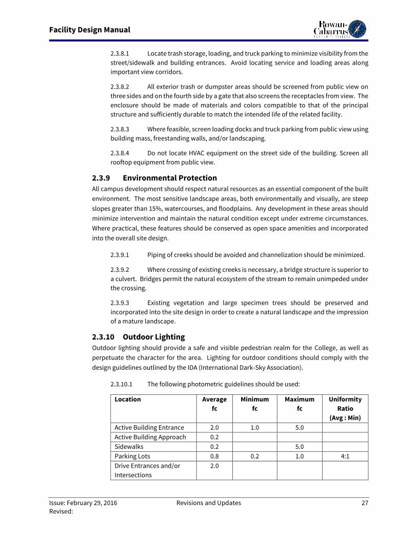
Facility Design Manual
Issue: February 29, 2016 Revisions and Updates 27
Revised:
2.3.8.1 Locate trash storage, loading, and truck parking to minimize visibility from the
street/sidewalk and building entrances. Avoid locating service and loading areas along
important view corridors.
2.3.8.2 All exterior trash or dumpster areas should be screened from public view on
three sides and on the fourth side by a gate that also screens the receptacles from view. The
enclosure should be made of materials and colors compatible to that of the principal
structure and sufficiently durable to match the intended life of the related facility.
2.3.8.3 Where feasible, screen loading docks and truck parking from public view using
building mass, freestanding walls, and/or landscaping.
2.3.8.4 Do not locate HVAC equipment on the street side of the building. Screen all
rooftop equipment from public view.
2.3.9 Environmental Protection
All campus development should respect natural resources as an essential component of the built
environment. The most sensitive landscape areas, both environmentally and visually, are steep
slopes greater than 15%, watercourses, and floodplains. Any development in these areas should
minimize intervention and maintain the natural condition except under extreme circumstances.
Where practical, these features should be conserved as open space amenities and incorporated
into the overall site design.
2.3.9.1 Piping of creeks should be avoided and channelization should be minimized.
2.3.9.2 Where crossing of existing creeks is necessary, a bridge structure is superior to
a culvert. Bridges permit the natural ecosystem of the stream to remain unimpeded under
the crossing.
2.3.9.3 Existing vegetation and large specimen trees should be preserved and
incorporated into the site design in order to create a natural landscape and the impression
of a mature landscape.
2.3.10 Outdoor Lighting
Outdoor lighting should provide a safe and visible pedestrian realm for the College, as well as
perpetuate the character for the area. Lighting for outdoor conditions should comply with the
design guidelines outlined by the IDA (International Dark-Sky Association).
2.3.10.1 The following photometric guidelines should be used:
Location Average
fc
Minimum
fc
Maximum
fc
Uniformity
Ratio
(Avg : Min)
Active Building Entrance 2.0 1.0 5.0
Active Building Approach 0.2
Sidewalks 0.2 5.0
Parking Lots 0.8 0.2 1.0 4:1
Drive Entrances and/or
Intersections
2.0
Facility Design Manual
Issue: February 29, 2016 Revisions and Updates 28
Revised:
Streets 0.4
2.3.10.2 Use a low intensity of high-quality white light, which will provide good, uniform
visibility while avoiding light pollution.
2.3.10.3 Cutoff fixtures are required because they are more efficient than non-cutoff
fixtures at casting light on the sidewalk and avoiding light spillage and pollution.
2.3.11 Site Amenities and Structures
Incorporate site furnishings (benches, tables, umbrellas, chairs, trash/recycling centers), including
engineering tie downs and foundations, where required, into design.
2.3.11.1 Utilize bench walls to establish the perimeter of gathering spaces. Tops shall
facilitate comfortable seating, while shedding moisture.
2.3.11.2 Anti-skate principles will be incorporated into all site design and amenities.
2.3.12 Public Art
Works of art have contributed to the visual quality of RCCC over a long period of time. This amenity
adds a visual texture and character that should be continued, as appropriate.
2.3.12.1 Public art should be constructed and placed to add beauty and character to
the campus. The piece of art should have meaning and give meaning to the campus and
inspiration to those that have the opportunity to see it.
2.3.12.2 Artwork may be free-standing pieces (e.g. sculpture or water fountain) or it
may be integrated into its surroundings as an architectural element (e.g. relief sculpture
imbedded in pavement or a wall, a mosaic or mural on a wall, lighting or sound effects, or
decorative railing or lighting).
2.3.12.3 All lighting of artwork should be in conformance with Campus Standards.
2.4. Site Circulation Elements These Design Guidelines encourage the development of a network of interconnecting streets that work
to disperse traffic while connecting and integrating various areas of the campus. Equally important,
these guidelines encourage the development of a network of pedestrian paths, sidewalks, and bicycle
lanes that provide an attractive and safe mode of travel for pedestrians and cyclists.
2.4.1 Access Management
The control of driveways, roadways, and other curb cuts through a comprehensive access
management program should be a high priority to maintain the efficient operation of the major
campus corridors, thereby securing the long-term infrastructure investment.
Street designs on the campus should permit the comfortable use of the street by cars, bicyclists,
and pedestrians. Pavement widths, design speeds, and the number of vehicle lanes should be
minimized without compromising safety. The specific design of any given street must consider the
building which fronts on the street and the relationship of the street to the campus’s street
network.
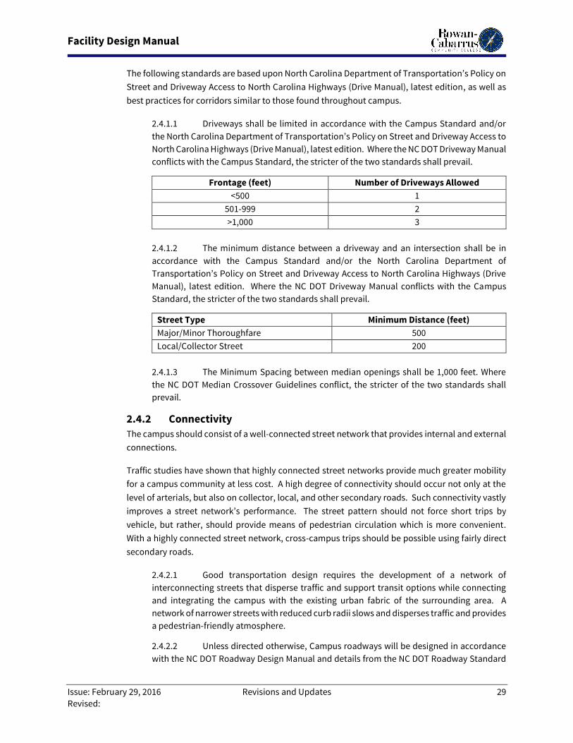
Facility Design Manual
Issue: February 29, 2016 Revisions and Updates 29
Revised:
The following standards are based upon North Carolina Department of Transportation’s Policy on
Street and Driveway Access to North Carolina Highways (Drive Manual), latest edition, as well as
best practices for corridors similar to those found throughout campus.
2.4.1.1 Driveways shall be limited in accordance with the Campus Standard and/or
the North Carolina Department of Transportation’s Policy on Street and Driveway Access to
North Carolina Highways (Drive Manual), latest edition. Where the NC DOT Driveway Manual
conflicts with the Campus Standard, the stricter of the two standards shall prevail.
Frontage (feet) Number of Driveways Allowed
<500 1
501-999 2
>1,000 3
2.4.1.2 The minimum distance between a driveway and an intersection shall be in
accordance with the Campus Standard and/or the North Carolina Department of
Transportation’s Policy on Street and Driveway Access to North Carolina Highways (Drive
Manual), latest edition. Where the NC DOT Driveway Manual conflicts with the Campus
Standard, the stricter of the two standards shall prevail.
Street Type Minimum Distance (feet)
Major/Minor Thoroughfare 500
Local/Collector Street 200
2.4.1.3 The Minimum Spacing between median openings shall be 1,000 feet. Where
the NC DOT Median Crossover Guidelines conflict, the stricter of the two standards shall
prevail.
2.4.2 Connectivity
The campus should consist of a well-connected street network that provides internal and external
connections.
Traffic studies have shown that highly connected street networks provide much greater mobility
for a campus community at less cost. A high degree of connectivity should occur not only at the
level of arterials, but also on collector, local, and other secondary roads. Such connectivity vastly
improves a street network’s performance. The street pattern should not force short trips by
vehicle, but rather, should provide means of pedestrian circulation which is more convenient.
With a highly connected street network, cross-campus trips should be possible using fairly direct
secondary roads.
2.4.2.1 Good transportation design requires the development of a network of
interconnecting streets that disperse traffic and support transit options while connecting
and integrating the campus with the existing urban fabric of the surrounding area. A
network of narrower streets with reduced curb radii slows and disperses traffic and provides
a pedestrian-friendly atmosphere.
2.4.2.2 Unless directed otherwise, Campus roadways will be designed in accordance
with the NC DOT Roadway Design Manual and details from the NC DOT Roadway Standard
Facility Design Manual
Issue: February 29, 2016 Revisions and Updates 30
Revised:
Drawings should be utilized. Main campus roads should have a cross-section width of 48’
and a posted speed limit of 20 MPH. Facility access roads should have a minimum cross-
section width of 36’ and a posted speed limit of 20 MPH. Service roads should have a
minimum cross-section width of 24’ and a posted speed limit of 15 MPH.
2.4.2.3 For good, clear visibility, intersections are to be perpendicular and have
lighting arranged at 90 degrees to each street. All landscaping and site amenities in excess
of 42” tall at maturity shall be located a minimum of 50’ behind the face of curbing at the
intersections.
2.4.3 Pedestrian and Bicycle Circulation
Provide a complete network of paths that interconnect building entrances, parking, transit stops,
sidewalks and crossings, adjacent properties, adjoining off-street paths, and other key
destinations on or adjacent to the site. Where sidewalks do not exist on connecting public
roadways, linkages should be advocated for during the site development permitting process.
2.4.3.1 Walks: Pedestrian pathways should be provided from the street to the parking
area between buildings, as necessary to ensure reasonably safe, direct and convenient
access to building entrances and off-street parking. Pedestrian routes should minimize
potential conflicts with vehicles. For pedestrian safety and comfort, where a main
pedestrian route must go along or across a parking lot or driveway, provide a separate path
with buffer landscaping and other amenities. Walks should not dead-end into the middle
of parking lots and other vehicular-oriented areas. Walks should be clearly defined and
enjoyable to use.
2.4.3.1.1 To aid pedestrian navigation and comfort, provide the following
elements along paths:
2.4.3.1.1.1 Landscaping, such as rows of trees and shrubs, flower beds,
and planters
2.4.3.1.1.2 Campus standard outdoor lighting fixtures
2.4.3.1.1.3 Small wayfinding signs
2.4.3.1.1.4 Vertical architectural elements, such as markers or arches
2.4.3.1.1.5 Seating and resting spots
2.4.3.1.1.6 Special paving to delineate seating and gathering spots.
2.4.3.1.2 Whenever pathways cross internal drives, provide a highly-visible
crosswalk made of a material that provides strong contrast with the vehicular
surface (imbedded elastomeric paint or unit pavers in concrete).
2.4.3.1.2.1 Consider elevating the crosswalk to the level of the
connecting walk. These elevated crosswalks will also serve to calm traffic
Facility Design Manual
Issue: February 29, 2016 Revisions and Updates 31
Revised:
which further enhances safety.
2.4.3.1.2.2 ADA Truncated Domes are required at the intersections
where primary pedestrian routes intersect roadways.
2.4.3.1.2.3 Cross walks shall be a minimum of a 10’ wide crosswalk, as
recommended by the Federal Highway Administration (FHA) Manual on
Uniform Traffic Control Devices (MUTCD).
2.4.3.1.2.4 Use warning signs and light fixtures to alert drivers to
crossings.
2.4.3.1.3 Provide pedestrian links to each adjacent property only where the
College and the adjacent property Owner have a written agreement. The links
should be highly visible and conveniently located. Avoid steps; provide curb ramps
to accommodate wheelchairs, bicycles, and baby strollers.
2.4.3.1.4 Consistent walkway widths should be maintained across the campus,
respond to pedestrian movement, and emphasize a hierarchy for pedestrian
circulation. No pedestrian path should be less than six feet (6’) in paved width.
Whenever parking abuts a walkway, (head-in, diagonal or parallel), add one-and-
one-half feet (1.5’) to the walkway width to accommodate car overhang or open
car doors, or provide wheel stops which hold the wheels at least two feet (2’) off the
sidewalk.
2.4.3.2 Bicycle Paths and Accommodations:
2.4.3.2.1 Multi-use paths (bicycle and pedestrian) should not be less than eight
feet (8’) in paved width. These should connect the campus network of paths with
every adjacent public roadway.
2.4.3.2.2 Bike racks or lockers should be located close to each building so they
are highly visible and convenient, but not on pedestrian courtyards. The racks
should be observable and well lit. To facilitate access, install a curb ramp in any
drive near the bike parking.
2.4.3.3 Ramps and Steps
2.4.3.3.1 Siting and building design should minimize the need for steps or
ramps. When possible, alternative grading measures should be considered.
2.4.3.3.2 Ramps should be installed for supply and service deliveries.
2.4.3.3.3 Ramps should be installed for accessibility for renovation projects.
2.4.3.3.4 Provide overhead exterior lighting for all steps and ramps. Recessed
wall or step lights below twenty-four inches (24”) are discouraged due to
maintainability issues.
2.4.3.3.5 All walking surfaces should have a surface providing traction.
Carborundum or similar abrasive will NOT be permitted.
2.4.3.3.6 The building design shall take into account the need to protect steps
Facility Design Manual
Issue: February 29, 2016 Revisions and Updates 32
Revised:
and ramps from the fall of snow from the roofs at entrances and along walkways.
2.4.4 Public Transit
The regional transit system should be maintained and enhanced as one of the greatest resources
of the campus and surrounding area.
2.4.4.1 Bus stops must be closely coordinated with the regional transit provider, but
should be ½ to 1 mile apart, unless increased speed and/or higher ridership justifies closer
placement. Shelters should be constructed where stops are not immediately adjacent to a
building with identified waiting area. Maximum distance from building exit to bus stop
should be two hundred feet (200’), otherwise a bus shelter should be planned.
2.4.4.2 All stops should be tied to the campus pedestrian circulation with paved walks
and crosswalks.
2.4.4.3 Bus shelter design shall be coordinated with transit system and college staff.
As a minimum, bus shelters shall be roofed, enclosed on three sides, have seating and space
for wheel chairs, and adequately lit. Solar bus shelters are highly encouraged and should
be investigated whenever a stop is planned.
2.4.5 Parking
Parking lots (and decks) should not dominate the frontage of pedestrian-oriented streets,
interrupt pedestrian routes, or negatively impact surrounding developments.
2.4.5.1 Parking lots or decks should be located behind buildings whenever possible.
Parking lots should not occupy more than 1/3 of the frontage of the adjacent building or no
more than sixty-four feet (64’), whichever is less.
2.4.5.2 Large surface parking lots larger than 75,000 square feet of vehicular surface
should be visually and functionally segmented into several smaller lots enclosed by
landscaping.
2.4.5.3 Parking lots along the street must be screened from the adjacent street and
sidewalk by a combination of berms, low walls, native stone, and landscaping.
2.4.5.4 One electric vehicle parking space with electrical power capacity and
infrastructure to support a 220V charging station should be planned in each major parking
area.
2.4.5.5 Incorporate Compact (with appropriate signage) and Standard parking spaces
in all parking areas.
2.4.5.6 As a minimum, include two (2) Van Accessible ADA parking spaces closest to
the main entrance and one Standard Accessible ADA space as close as possible to the main
entrance of each building.
2.4.5.7 Parking lots should be designed to support video surveillance, emergency call
stations with mass notification, and wayfinding/emergency notification digital messaging
signs.
Facility Design Manual
Issue: February 29, 2016 Revisions and Updates 33
Revised:
2.4.6 Wayfinding
Appropriate interior and exterior wayfinding signage shall be incorporated into all projects.
Wayfinding signage will include a combination of permanent, and changeable, electronic signage.
2.4.6.1 Major entries to each campus shall have a marquee with changeable electronic
message board to announce the daily activities at the campus.
2.4.6.2 Interior fixed and changeable message boards shall be located to guide visitors
to campus events.
2.4.6.3 Permanent signage on drives will announce the location and major tenants of
every building.
2.4.7 Landscaping
The landscape of the College’s campuses creates a sense of place for the students, faculty, and
visitors to the campus. This sense of place encourages social interaction which is a vital aspect of
any pedestrian campus. Because the area is composed of diverse site and building elements, the
landscape character is the integral component that serves to unify and create an attractive whole.
As outlined in the Guiding Principles, it is important that the “College emphasize the quality of the
natural environment” and “preserve the natural habitat”. As the campus continues to grow and
evolve, dedicated landscaped open space should be protected, preserved, and enhanced as
appropriate. Open space preservation and creation will be vital to the health, function, and beauty
of the overall campus. The plan proposes a mix of formal and informal areas that recognize the
existing conditions and build upon the inherent beauty of the campus. For this reason, it is
imperative that existing plant material be integrated into the overall concept of the landscape
plan for a specific project, as well as the use of indigenous plant material that enhances the
overriding sustainable approach to the campus environment. Developing a campus landscape
that is aesthetically attractive while also being practical and cost-effective to maintain is also
critical. Safety in the landscape is a serious consideration which should be addressed through
incorporation of the principles of Crime Prevention through Environmental Design (CPTED) that
discourage designs that create “hiding places”.
2.4.7.1 General:
2.4.7.1.1 All new construction and major renovations and remodels affecting
the site and exterior envelope of the building, will include a complete landscaping
plan, which includes plantings at all facades of the buildings and parking areas. For
renovations and remodels, this may only be an enhancement or refurbishment of
a previously executed landscaping plan.
2.4.7.1.2 Trees and other plantings should to be selected, sized and located so
as not to disrupt site lighting, paths, and security both at the time of initial planting
but also at maturity. These landscape elements should be coordinated with Site
Photometrics and Security planning during the Design Phases of the project. For
specific material suggestions and size requirements, please refer to Section 3 –
College Standards.
2.4.7.1.3 Minimize site disturbance and erosion through retention of existing
Facility Design Manual
Issue: February 29, 2016 Revisions and Updates 34
Revised:
vegetation and by avoiding development in sensitive areas.
2.4.7.1.4 Enhance existing streams, ponds, and watersheds with overhanging
trees, rock and plant materials appropriate to a piedmont stream.
2.4.7.2 Trees
2.4.7.2.1 Existing trees shall be preserved whenever feasible.
2.4.7.2.2 New tree plantings will be made on a regular basis and existing
mature trees and quality tree stands should be protected as an available campus
resource.
2.4.7.2.3 New construction on campus, whether it be expansion or infill related,
begins to put intense pressure on existing, mature trees and often results in the
compaction of their critical root zone. All new projects should consider this fact
and plan to enforce tree protection measures and enhance the site with new tree
plantings.
2.4.7.2.4 Many of the older trees on campus will inevitably become less viable
and will be lost to disease or other causes at some point in the future. The
preservation, protection, and ongoing health of campus trees should never be a
second priority for any proposed project.
2.4.7.2.5 When selecting which trees to preserve, the following shall be
considered: existing and proposed grading, age and vigor, condition and type of
tree, location of site improvements, utility connections, wildlife, and
environmental benefits.
2.4.7.2.6 Trenching, placing backfill in the critical root zone, driving or parking
equipment in the critical root zone, and dumping of materials detrimental to plant
health in close proximity of a tree to be preserved is prohibited.
2.4.7.2.7 Should any tree designated for preservation within the lines of
demarcation for a construction project die during or within the warranty period of
the project, the contractor shall be responsible to replace it with a size and species
type approved by the College.
2.4.7.2.8 Prior to grading, protective barricades shall be placed around all trees
designated to be saved.
2.4.7.2.9 Establish new tree plantings along all major walkways and major
campus streetscapes.
2.4.7.3 Plantings
2.4.7.3.1 Select plants for the campus that are native to the bio-region, long-
lived, relatively pest free, drought tolerant, and practical to maintain.
2.4.7.3.2 Define outdoor living spaces and quads with plantings to create
informal gathering spaces with access to seating.
2.4.7.3.3 Provide landscape screening around exposed building equipment
such as transformers or mechanical units. Plants specified for this screening to be
Facility Design Manual
Issue: February 29, 2016 Revisions and Updates 35
Revised:
‘slow growing’ or not need frequent trimming, that would otherwise hinder
operation or maintenance of, or access to, the units being screened.
2.4.7.3.4 Distinguish the corners of street intersections, particularly gateways
and site entries (from both street and sidewalk) by special landscape treatments:
flower displays, specimen trees and shrubs, accent rocks, low walls, signage,
decorative lighting, sculpture, architectural elements, and/or brick paving.
Features for vehicular entry points must meet NCDOT’s sight triangle
requirements.
2.4.7.3.5 Balance the plantings (softscape) with the special paved areas
(hardscape). Whenever possible, pervious paving systems should be utilized to
decrease stormwater runoff and its effects.
2.4.7.4 Open Space
2.4.7.4.1 To ensure that open space is well used, it is essential to locate and
design it carefully. The space should be located where it is visible and easily
accessible from public areas (building entrances, sidewalks). Consider views and
sun exposure as well.
2.4.7.4.2 New open spaces should contain direct access from the adjacent
streets. They should be open along the adjacent sidewalks and allow for multiple
points of entry. They should also be visually permeable from the sidewalk, allowing
passersby to see directly into the space.
2.4.7.4.3 The space should be well-buffered from moving cars so that users can
enjoy and relax in the space. The space may be visible from streets or internal
drives, but should not be wholly exposed to them. Partially enclose the space with
building walls, freestanding walls, landscaping, raised planters, or on-street
parking to help buffer it and create a comfortable “outdoor room”.
2.4.7.4.4 Do not overlook general open spaces (not part of the dedicated open
space). These areas help tie the campus together into a memorable experience,
thus giving them great value.
2.4.7.4.5 The design of these spaces can be enhanced with plazas, fountains or
public art.
2.4.7.4.6 Maintaining open spaces at varying scales is also important and
encourages both passive and active spaces within the campus setting.
2.4.7.4.7 Conserve open land, including those areas containing unique and
sensitive features such as natural areas, wildlife habitat, streams or creeks,
wetlands, and floodways.
2.4.7.4.8 Lands to be preserved as open space should include wetlands,
floodways, soils unsuitable for development, mature woodlands, significant
wildlife habitat, and historic archaeological and cultural features.
2.4.7.4.9 Create additional open grassed areas, where possible, to provide an
enjoyable place for relaxation and recreation.
Facility Design Manual
Issue: February 29, 2016 Revisions and Updates 36
Revised:
2.4.7.4.10 For supplemental lighting or operable site features at remote
locations, consider commercial grade, solar powered devices in lieu of electric.
2.5. Buildings While Rowan-Cabarrus Community College does not have a single consistent vocabulary of architecture
on campus, there are a number of key elements and details found in many of the newer buildings on
campus. In order for new buildings or additions to be integrated into the fabric of the campus, it is
important for the Designer to be aware of such building attributes.
The architectural style of each campus, as defined by the College, is identified in the Campus Standards.
It is the desire of the College that all new structures constructed on any campus follow the identified
genre and not deviate significantly in terms of palate of materials or colors, unless specifically directed.
The intent of the guidelines is to loosely define the elements of a building in order to maintain a
consistent vocabulary for each new project on campus.
2.5.1 Building Form and Massing
Building form and scale should be of human proportion. The massing of existing buildings on the
College’s campuses are one to three stories in height and it is generally recognized, given the
escalating value of land, that future buildings should be planned as three to four stories in height,
where compatible with the program elements planned for the building. All new buildings will be
based on a highly efficient, cost effective, grid layout. The interface of interior and exterior space
through the use of covered entries, arcades, or courtyards should be considered in the initial form
of the building. In addition, the massing should respond to the size of the adjacent context, as well
as the functional requirements of the program. Some design elements to consider in designing
proportionately scaled buildings include:
2.5.1.1 Recess entries at ground level.
2.5.1.2 Alter exterior walls in depth and dimension.
2.5.1.3 Introduce a base or plinth to the lower level of the building.
2.5.1.4 Vary the heights of the building to create distinct or separate massing.
2.5.1.5 Articulate the building façade with humanly proportioned windows or
openings.
2.5.2 Facades
Each building façade should be articulated in a simple, consistent manner.
2.5.2.1 Curved facades should be avoided.
2.5.2.2 Brick will be the standard exterior finish of all College buildings.
2.5.2.3 Windows or openings should be spaced at regular intervals to create a
horizontal pattern along the façade. This may vary depending on the function and scale of
the structure.
2.5.2.4 The Designer should carefully consider the relationship between roof forms
and massing when developing the design for the elevations of the building. Structural
Facility Design Manual
Issue: February 29, 2016 Revisions and Updates 37
Revised:
expression at the exterior may be included but should be incorporated in a thoughtful
manner.
2.5.2.5 In general, design elements of the façade should appear to become “lighter”
in the order from bottom to top of building (heavier base: lighter top).
2.5.2.6 The use of more than three (3) primary building materials is discouraged.
2.5.2.7 Accent details of precast or stone should be included to add design interest.
2.5.3 Entrances
Placing the main entrance is perhaps the single most important step the Designer takes during the
evolution of a building plan.
2.5.3.1 Placement of the main entrance should face primary pedestrian routes. The
main entrance must be a bold, visible shape, which is a significant feature of the design for
the facility.
2.5.3.2 All entries must be easily identifiable and visually impressive for those entering
the building. Covered entrances are preferred by the College to protect students, faculty,
staff, and visitors from snow or inclement weather upon entering the building.
2.5.3.3 Primary and secondary entries should be connected internally with a direct
route to allow pedestrian passageway from building to building on campus.
2.5.4 Roofs
Flat or low slope roofs are the most efficient, durable roof and will be the standard on all new
buildings. Other roof forms may be considered to bring emphasis to discreet areas of buildings.
Special attention should be given by the Designer to the roof forms.
2.5.4.1 Roof forms should be designed carefully with other massing elements of the
building.
2.5.4.2 When possible, mechanical equipment should not be located on the roof. In
addition, penetrations of any roof system should be kept to a minimum.
2.5.4.3 Roof access must be as safe as possible.
2.5.4.3.1 In multi-story buildings, permanent access shall be provided to every
major roof level.
2.5.4.3.1.1 In multi-story buildings, primary roof access will be via an
extension of a stair tower to the main roof level. Access to the stair leading
to the roof level will be via a door at the highest publicly accessible stair
landing.
2.5.4.3.1.2 In a single-story building and in major renovations, brows
and awnings are excluded.
2.5.4.3.2 Public access to any roof area is not acceptable. Ladders inside
closets are not acceptable.
Facility Design Manual
Issue: February 29, 2016 Revisions and Updates 38
Revised:
2.5.4.3.3 Fall prevention (creating situations where a fall would be difficult or
impossible) and fall protection (creating a system which will protect against a fall)
will be factored into all new roof designs and added in any re-roof project. A
parapet with a minimum height of 42-48 inches above the adjacent roof surface will
be the preferred method of roof fall prevention and is easily facilitated in flat roof
designs.
2.5.4.3.4 Systems
2.5.4.3.4.1 Plumbing: A water spigot shall be provided at every major
roof level.
2.5.4.3.4.2 Power: A convenience electrical outlet shall be located in
close proximity to any roof-mounted equipment.
2.5.4.3.4.3 Solar: Accommodation for Solar Photovoltaic and Thermal
(hot water) shall be considered in the design of all major roof areas.
2.5.5 Fenestration
Windows and doors located in exterior walls should be recessed to create shade and shadow along
the building façade.
2.5.5.1 Openings are another means for providing an appropriate human scale to the
exterior appearance of a structure. Appropriately sized individual windows or openings,
treated as penetrations of the wall surface, are preferred to large expanses of glass.
2.5.5.2 Larger openings may be used to express principle entries or gateways, or as
vertical separation of massing along a building façade.
2.5.5.3 Orientation and solar gain of openings should be a priority for the design of the
exterior.
2.5.5.4 Appropriate overhangs or screening devices should be considered.
2.5.5.5 Windows with clear (Low-E) glass are recommended to be used where feasible.
2.5.6 Structure
Building structure will be a cost effective grid layout which maximizes flexible interior space and
minimizes odd angles and curves which create inefficient layouts.
2.5.6.1 Structure and cladding should be designed with an eye towards an easily
maintainable, 100-year life facility.
2.5.6.2 Structural steel will be the standard. Other systems can be considered where
they show significant life cycle or flexibility benefits.
2.5.6.3 Concrete decks on steel pan will be the standard for floor construction.
Alternate substrate options on steel deck may be considered for roof decks. Other systems
can be considered where they show significant life cycle or flexibility benefits.
2.5.6.4 Masonry precast panel cladding with integral, full panel insulation and thin
brick inserts will be the standard. A site cast tilt-wall system is also acceptable. Other
Facility Design Manual
Issue: February 29, 2016 Revisions and Updates 39
Revised:
systems can be considered where they show significant life cycle or flexibility benefits.
2.5.6.5 Architectural elements which serve a primary aesthetic purpose (towers,
bastions, etc.) while creating interior space with limited function, should be avoided. With
the exception of mechanical penthouses, all interior space must be ADA accessible.
2.5.7 Arcades
Arcades, archways, or colonnades may be incorporated into the design of the exterior.
2.5.7.1 These elements may be freestanding or integrated into the building façade.
2.5.7.2 The height-to-length ratio should be expressed proportionately to human
scale.
2.5.7.3 Materials must be able to withstand the weather, insects, etc. to provide a
minimum 20-year lifespan.
2.5.7.4 Fabric awnings are not acceptable.
2.5.8 Basements
Full Basements will generally be avoided, unless a specific need is identified. Where topography
dictates, occupiable floors of a building may be cut into a hillside.
2.5.7.1 Any occupiable area below grade shall be protected against ground
water/moisture intrusion by a combination of membrane, drainage board, and pipes or
conduits to move the moisture away from the building foundation.
2.5.7.2 Exterior basement walls will generally be reinforced, cast in place concrete.
2.6. Building Interior
2.6.1 General
2.6.1.1 Incorporate ANSI S12.60 Acoustical Performance Criteria, Design
Requirements and Guidelines for Schools into the design of all interior spaces, particularly
as it relates to sound transmission, reverberation times, and background noise levels. This
requires that careful consideration be given not just to the finishes of interior spaces, but
also to the building placement, the structural and building envelope, and mechanical and
electrical systems.
2.6.1.2 Ensure all architectural elements within sight-lines correlate (i.e. all
doors/frames/hardware on a corridor appear uniform, doors/window frames/storefront on
a façade match in finish, terrazzo flooring is extended from existing corridors into new
spaces, terminating at a logical break point, etc.).
2.6.2 Walls
2.6.2.1 The standard for interior walls shall be painted 5/8” gypsum board over
minimum 3-5/8” 25 ga. metal studs, 16” on center, with empty cavities, unless there are
issues in the space regarding durability, security, acoustics, moisture, special use, etc. Size
and thickness of studs to be heavier as necessary to meet minimum deflection criteria.
2.6.2.2 Spaces requiring sound mitigation will have wall sections based on those
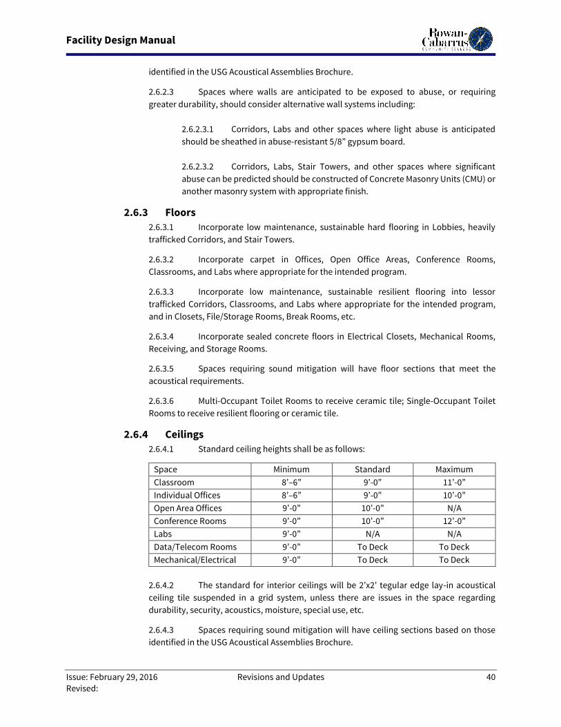
Facility Design Manual
Issue: February 29, 2016 Revisions and Updates 40
Revised:
identified in the USG Acoustical Assemblies Brochure.
2.6.2.3 Spaces where walls are anticipated to be exposed to abuse, or requiring
greater durability, should consider alternative wall systems including:
2.6.2.3.1 Corridors, Labs and other spaces where light abuse is anticipated
should be sheathed in abuse-resistant 5/8” gypsum board.
2.6.2.3.2 Corridors, Labs, Stair Towers, and other spaces where significant
abuse can be predicted should be constructed of Concrete Masonry Units (CMU) or
another masonry system with appropriate finish.
2.6.3 Floors
2.6.3.1 Incorporate low maintenance, sustainable hard flooring in Lobbies, heavily
trafficked Corridors, and Stair Towers.
2.6.3.2 Incorporate carpet in Offices, Open Office Areas, Conference Rooms,
Classrooms, and Labs where appropriate for the intended program.
2.6.3.3 Incorporate low maintenance, sustainable resilient flooring into lessor
trafficked Corridors, Classrooms, and Labs where appropriate for the intended program,
and in Closets, File/Storage Rooms, Break Rooms, etc.
2.6.3.4 Incorporate sealed concrete floors in Electrical Closets, Mechanical Rooms,
Receiving, and Storage Rooms.
2.6.3.5 Spaces requiring sound mitigation will have floor sections that meet the
acoustical requirements.
2.6.3.6 Multi-Occupant Toilet Rooms to receive ceramic tile; Single-Occupant Toilet
Rooms to receive resilient flooring or ceramic tile.
2.6.4 Ceilings
2.6.4.1 Standard ceiling heights shall be as follows:
Space Minimum Standard Maximum
Classroom 8’–6” 9’-0” 11’-0”
Individual Offices 8’–6” 9’-0” 10’-0”
Open Area Offices 9’-0” 10’-0” N/A
Conference Rooms 9’-0” 10’-0” 12’-0”
Labs 9’-0” N/A N/A
Data/Telecom Rooms 9’-0” To Deck To Deck
Mechanical/Electrical 9’-0” To Deck To Deck
2.6.4.2 The standard for interior ceilings will be 2’x2’ tegular edge lay-in acoustical
ceiling tile suspended in a grid system, unless there are issues in the space regarding
durability, security, acoustics, moisture, special use, etc.
2.6.4.3 Spaces requiring sound mitigation will have ceiling sections based on those
identified in the USG Acoustical Assemblies Brochure.
Facility Design Manual
Issue: February 29, 2016 Revisions and Updates 41
Revised:
2.6.4.4 All ceiling tiles and grid will be a product and material specifically
manufactured for that purpose.
2.6.4.5 Restroom ceilings will be painted 5/8” gypsum board attached to a suspended
grid for security.
2.6.5 Systems
2.6.5.1 General
2.6.5.1.1 Demolish and remove all abandoned elements from previous systems
and any systems unused or made obsolete by the planned remodel/renovation. No
abandonment in place is acceptable.
2.6.5.1.2 Install individual metering into all utilities servicing any new building
or significant renovation/remodel of an existing building. Meters should tie into
the campus BAS.
2.6.5.1.3 All vibration generating or vibration sensitive equipment will be
mounted on vibration dampening feet, bases, or suspension systems. Piping and
ducting systems shall include vibration dampeners at any connection to similar
equipment.
2.6.5.2 Electrical
2.6.5.2.1 All electrical panels shall be located in dedicated Electrical Rooms,
with the exception of subpanels serving special needs spaces which will be located
in those spaces. In major remodels and renovations, these Electrical Rooms shall
be created, and existing panels in public spaces shall be removed, with the circuitry
relocated to the Electrical Room. Any panel remaining in a space accessible to
students, faculty, or non-facilities staff will be provided with a locking face.
2.6.5.2.2 Consider the installation of roof-mounted solar energy harvesting
system (photovoltaic) on any new building and in any existing building being
substantially remodeled/renovated. This will include a structural evaluation of the
roof as well as an analysis of remaining life of the roofing system.
2.6.5.2.3 Emergency Generators and other power generating systems should
be monitored and controlled by the campus BAS.
2.6.5.3 Mechanical
2.6.5.3.1 Follow the Rowan-Cabarrus Community College HVAC Design
Standards.
2.6.5.3.2 All HVAC systems to be monitored and controlled by the campus BAS.
2.6.5.3.3 Existing pneumatically controlled systems will be replaced with
digital control systems within the established lines of demarcation of all
renovation/remodel projects.
Facility Design Manual
Issue: February 29, 2016 Revisions and Updates 42
Revised:
2.6.5.3.4 Consider installation of roof-mounted solar energy harvesting system
(hot water) on any new building and in any existing building being substantially
remodeled/renovated.
2.6.5.4 Life Safety
2.6.5.4.1 Install fire sprinkler system in all new buildings and in any existing
building being substantially remodeled/renovated. This may entail expanding the
lines of demarcation for this element of the project if the Authorities Having
Jurisdiction (AHJ) requires the whole building be sprinkled.
2.6.5.4.2 Install new voice annunciated Fire Alarm System in all new buildings
and in any existing building being substantially remodeled/renovated. New fire
alarms system(s) will integrate within the existing campus fire alarm system
allowing building level visibility to outside monitoring.
2.6.5.5 Security
2.6.5.5.1 Electronic Access Controls
2.6.5.5.1.1 Each building will have door controls and hardware which
are tied into the College-wide Electronic Access Control System.
2.6.5.5.1.2 Typically, one Card Key Controlled Access Point will be
provided on each building. This location will be selected based on CPTED
Principles, but is usually the main entrance to a building.
2.6.5.5.1.3 Public access doors to a building will be provided with
locksets capable of being locked remotely via the electronic access control
system and locally with a key.
2.6.5.5.1.4 Emergency egress doors and doors to service spaces will
have position monitoring sensors installed which tie into the electronic
access control system. These doors shall be provided with door closers
and appropriate locksets to ensure that they remain normally closed and
latched.
2.6.5.5.1.5 Door hardware to classrooms, labs, offices, office, suites,
conference rooms, and other “normally occupiable” spaces will be
provided with a means of securing the space, by any occupant, from inside
the space in the case of an emergency.
2.6.5.5.2 Emergency Communications
2.6.5.5.2.1 Mass Notification:
2.6.5.5.2.1.1 Each building will have speakers and other
communications appliances which tie into the College-wide Mass
Notification System.
2.6.5.5.2.1.2 Classroom, Labs, Office Areas, and Conference
Rooms will be provided with telephone handsets with speakers,
Facility Design Manual
Issue: February 29, 2016 Revisions and Updates 43
Revised:
which will act as the annunciator for the Mass Notification System.
2.6.5.5.2.1.3 Corridors, Lobbies and other interior public spaces
will be provided with ceiling-mounted speakers to act as
annunciators for mass notification.
2.6.5.5.2.1.4 Areas outside buildings will be served will wall-
mounted speakers to annunciate the mass notification
communications.
2.6.5.5.2.1.5 Parking Lots and other common outdoor areas
remote from buildings will be provided with pole-mounted
emergency phones, which shall also act as annunciators for the Mass
Notification System.
2.6.5.5.2.1.6 Mass Notification System shall be tied into the
Building or Campus Emergency Power System.
2.6.5.5.2.2 Campus Emergency Phones
2.6.5.5.2.2.1 One wall-mounted emergency phone will
be provided on each floor of every building; this phone will also act as
an annunciator for the Mass Notification System.
2.6.5.5.2.2.2 Parking Lots and other common outdoor areas
remote from buildings will be provided with pole-mounted
emergency phones.
2.6.5.5.3 Video Surveillance System
2.6.5.5.3.1 Each building will be provided with video surveillance
cameras which tie into the College-wide Video Surveillance System. Video
Surveillance System shall be tied into the Building or Campus Emergency
Power System.
2.6.5.5.3.2 The primary purpose of the Video Surveillance System is to
document access into the campus and each building. Cameras will be
strategically located to view the approaches to and access points into a
building, and onto floors within a building.
2.6.5.5.3.3 Cameras may be installed in areas where there is elevated
risk of theft or misbehavior.
2.6.5.5.3.4 Cashier Stations will have cameras to capture the handling of
cash and the customer interface.
2.6.5.5.3.5 All Elevators will have ceiling-mounted surveillance cameras.
2.6.5.5.3.6 Emergency Phone Poles in Parking Lots and other common
Facility Design Manual
Issue: February 29, 2016 Revisions and Updates 44
Revised:
outdoor areas will be provided with pole-mounted cameras.
2.6.5.5.3.7 Data/Communication: Data Cabling and Infrastructure shall
be in compliance with the College’s Telecommunications Standard,
including the qualifications.
2.7. Spaces Although not intended to be comprehensive, the following are general guidelines for the space which
may be created within the College’s buildings.
2.7.1 General
2.7.1.1 Incorporate ANSI S12.60 Acoustical Performance Criteria, Design
Requirements and Guidelines for Schools into the design of all interior spaces.
2.7.1.2 Ensure all architectural elements within sight-lines correlate (i.e. all
doors/frames/hardware on a corridor appear uniform, doors/window frames/storefront on
a façade match in finish, terrazzo flooring is extended from existing floor into new spaces,
terminating at a logical break point, etc.).
2.7.1.3 Every effort will be made to provide daylighting of all instructional and office
spaces. Windows shall be a minimum of 8” AFF and shall not extend above the ceiling height
of the room.
2.7.1.4 All Offices, Classrooms, Conference Rooms, Laboratories, and Break Rooms
shall have doors with sidelites and/or transoms to facilitate security and moving natural
light into corridors and interior spaces.
2.7.1.5 Door hardware to classrooms, labs, offices, office suites, conference rooms,
and other “normally occupiable” spaces will be provided with a means of securing the
space, by any occupant, from inside the space in the case of an emergency.
2.7.1.6 HVAC Supply and Returns to be alternately located high and low, and on
opposite ends of the Classroom, to maximize air flow through room.
2.7.1.7 Use RCCC Furnishing Standards and prototypical office and cubicle layouts
when laying out spaces, including power, lighting, and ventilation. This is particularly
critical as it pertains to switching, placement of thermostats, and other controls. All
furnishings to be specified/designed to allow for flexibility and multiple room layouts and
uses.
2.7.2 Classrooms
Classrooms will be the primary locations for instructor-led educational experiences. They shall
support diverse educational pedagogies. Each classroom building shall have a mix of Small,
Standard, and Large Classrooms to ensure maximum utilization. Associated classrooms shall be
located in close proximity to Lab spaces to support the classroom instruction portion of Lab
sections. Ensure ample consideration is given to classroom acoustics, particularly as it relates to
sound transmission, reverberation times, and background noise levels.
2.7.2.1 General

Facility Design Manual
Issue: February 29, 2016 Revisions and Updates 45
Revised:
2.7.2.1.1 Entry doors shall be located at the rear of the classroom to minimize
disruption of entry during instruction.
2.7.2.1.2 To facilitate multiple program uses of the classroom, storage closets
should be included where instructional aids are needed.
2.7.2.1.3 Provide space allocation at the front of the room, as well as power
and data, for Smart Podium, Interactive Whiteboards, and Projector (if intended)
in each Classroom.
2.7.2.1.4 Chair rail on all walls; height as necessary based on specified chairs.
2.7.2.1.5 Clip strips are to be provided on side walls to facilitate presentation
of teaching aids.
2.7.2.2 Small Classroom
2.7.2.2.1 Size: 18 to 20 Student Stations which, at 30 sf per Student Station,
yields a space of no larger than 600 sf.
2.7.2.2.2 Envelope:
2.7.2.2.2.1 Walls: Walls from floor to underside of deck, minimum STC
Rating 52, painted.
2.7.2.2.2.2 Ceiling: Acoustical ceiling tile.
2.7.2.2.2.3 Floors: Depending on the planned educational program,
carpet or resilient flooring, rubber base.
2.7.2.2.2.4 Fenestration: Solid wood door with sidelite. Exterior
windows or glazing is preferred.
2.7.2.2.2.5 Fit Out: White Board on the Teaching Wall.
2.7.2.2.3 Storage: None.
2.7.2.2.4 Systems:
2.7.2.2.4.1 Lights: 2 x 4 general lighting.
2.7.2.2.4.2 Power: Electrical receptacles to support technology, provide
general housekeeping, and provide the flexibility to provide a powered
row of tables for student convenience.
2.7.2.2.4.3 HVAC: Branch lines from trunk line (outside of Classroom
envelope). Branch lines should not extend from one Classroom to
Facility Design Manual
Issue: February 29, 2016 Revisions and Updates 46
Revised:
another. Where not provided with a ducted return to air handling units,
return air to plenum via sound mitigating transfer duct.
2.7.2.2.4.4 Data: Data receptacles as necessary to support technology.
Wireless access point in ceiling to support student connectivity.
2.7.2.2.5 Technology:
2.7.2.2.5.1 Smart Podium, with connections to Network and Projector.
2.7.2.2.5.2 Short throw networked projector.
2.7.2.2.5.3 Ceiling mounted speakers connected to Smart Podium.
2.7.2.2.6 Furnishings: Tables and chairs as needed to fulfill the intended use of
the space.
2.7.2.2.7 Related Spaces: None.
2.7.2.2.8 Adjacencies: Divisional/Departmental Office Suite.
2.7.2.3 Standard Classroom
2.7.2.3.1 Size: 24 to 30 Student Stations which, at 25 sf per Student Station,
yields a space of no larger than 750 sf.
2.7.2.3.2 Envelope:
2.7.2.3.2.1 Walls: Walls from floor to underside of deck. Minimum STC
Rating 52, painted.
2.7.2.3.2.2 Ceiling: Acoustical ceiling tile. Large spaces may require
enhanced acoustical ceiling tiles.
2.7.2.3.2.3 Floors: Depending on the planned educational program,
carpet or resilient flooring, rubber base.
2.7.2.3.2.4 Fenestration: Solid wood door with sidelite.
2.7.2.3.2.5 Fit Out: White Board on the Teaching Wall.
2.7.2.3.2.6 Storage: None.
2.7.2.3.3 Systems:
2.7.2.3.3.1 Lights: 2 x 4 general lighting.
Facility Design Manual
Issue: February 29, 2016 Revisions and Updates 47
Revised:
2.7.2.3.3.2 Electrical receptacles to support technology, provide general
housekeeping, and provide the flexibility to provide a powered row of
tables for student convenience.
2.7.2.3.3.3 HVAC: Branch lines from trunk line (outside of Classroom
envelope). Branch lines should not extend from one Classroom to
another. Where not provided with a ducted return to air handling units,
return air to plenum via sound mitigating transfer duct.
2.7.2.3.3.4 Data: Data receptacles as necessary to support technology.
Wireless access point in ceiling to support student connectivity.
2.7.2.3.4 Technology:
2.7.2.3.4.1 Smart Podium, with connections to Network and Projector.
2.7.2.3.4.2 Short throw networked projector.
2.7.2.3.4.3 Ceiling mounted speakers connected to Smart Podium.
2.7.2.3.5 Furnishings: Tables and chairs as needed to fulfill the intended use of
the space.
2.7.2.3.6 Related Spaces: Storage Closet.
2.7.2.3.7 Adjacencies: Divisional/Departmental Office Suite.
2.7.2.4 Large Classroom
2.7.2.4.1 Size: 30 to 40 Student Stations which, at 25 sf per Student Station,
yields a space of no larger than 1,000 sf.
2.7.2.4.2 Envelope:
2.7.2.4.2.1 Walls: Walls from floor to underside of deck. Minimum STC
Rating 52, painted.
2.7.2.4.2.2 Ceiling: Acoustical ceiling tile.
2.7.2.4.2.3 Floors: Depending on the planned educational program,
carpet or resilient flooring, rubber base.
2.7.2.4.2.4 Fenestration: Solid wood door with sidelite. Exterior
windows or glazing is preferred.
2.7.2.4.2.5 Fit Out:
2.7.2.4.2.6 Storage: None.
Facility Design Manual
Issue: February 29, 2016 Revisions and Updates 48
Revised:
2.7.2.4.3 Systems:
2.7.2.4.3.1 Lights: 2 x 4 general lighting.
2.7.2.4.3.2 Power: Electrical receptacles to support technology, provide
general housekeeping, and provide the flexibility to provide a powered
row of tables for student convenience.
2.7.2.4.3.3 HVAC: Branch lines from trunk line (outside of Classroom
envelope). Branch lines should not extend from one Classroom to
another. Where not provided with a ducted return to air handling units,
return air to plenum via sound mitigating transfer duct.
2.7.2.4.3.4 Data: Data receptacles as necessary to support technology.
Wireless access point in ceiling to support student connectivity.
2.7.2.4.4 Technology:
2.7.2.4.4.1 Smart Podium, with connections to Network and Projector.
2.7.2.4.4.2 Short throw networked projector.
2.7.2.4.4.3 Ceiling mounted speakers connected to Smart Podium.
2.7.2.4.5 Furnishings: Tables and chairs as needed to fulfill the intended use of
the space.
2.7.2.4.6 Related Spaces: Storage Closets (Multiple).
2.7.2.4.7 Adjacencies: Divisional/Departmental Office Suite.
2.7.3 Laboratories
Laboratories will be the primary location for hands-on student application of instructor-led
education, and shall support the educational needs of the appropriate curriculum. Labs shall be
located in close proximity to the associated classrooms, and should be designed to serve specific
programs, without duplicating space needs and equipment. Locking Storage closets should be
provided for instructional aids and equipment. Provide power and data in each Lab, and at each
lab counter as appropriate for the equipment utilized. Exterior windows in Labs are preferred. Lab
program and requirements will be established at the Programming Phase.
2.7.4 Lecture Halls and Auditoriums
Lecture Hall and Auditoriums provide large spaces to accommodate instructor delivered
programs. The program and requirements will be established at the Programming Phase.
2.7.5 Offices
2.7.5.1 Individual Offices
2.7.5.1.1 President:
Facility Design Manual
Issue: February 29, 2016 Revisions and Updates 49
Revised:
The President’s Office is typically associated with a President’s Suite which would
have a waiting area; a President’s Assistant’s cubicle with reception counter, acting
as the reception point for the space; and, other offices and cubicles for the
President’s support staff. This President’s Suite would include a Storage/File
Room, a Work Room, and the President’s Conference Room.
2.7.5.1.1.1 Size: Roughly 250 sf, including informal seating area for four.
2.7.5.1.1.2 Envelope:
2.7.5.1.1.2.1 Walls: Masonry walls from floor to underside of deck,
sheathed in gypsum board. Minimum STC Rating 52, painted, wood
crown molding and base.
2.7.5.1.1.2.2 Ceilings: Acoustical ceiling tile.
2.7.5.1.1.2.3 Floors: Carpet with wood base.
2.7.5.1.1.2.4 Fenestration: Solid wood door with no sidelite.
Windows to exterior on two walls.
2.7.5.1.1.3 Systems:
2.7.5.1.1.3.1 Lights: 2 x 4 general lighting with accent lights as
necessary, controlled by dimming system.
2.7.5.1.1.3.2 Power as required for all areas of work within the
office.
2.7.5.1.1.3.3 HVAC: Separate individual zone with thermostat.
2.7.5.1.1.3.4 Technology: Data receptacle at desk. Ensure
wireless connectivity to the network.
2.7.5.1.1.3.5 Security: Electronic locks with Card Reader on any
doors that could provide access to any of the President’s spaces.
2.7.5.1.1.4 Furnishings: Wood Executive Double Pedestal Desk with
Bridge, Credenza with Hutch, Executive Leather Office Chair, 2 guest
chairs, 4 Lounge Chairs, Coffee Table, End Table, other furnishings as
required. Confirm re-use of existing President’s Suite Furnishings and
ensure spaces are configured to accommodate.
2.7.5.1.1.5 Related Spaces:
2.7.5.1.1.5.1 Coat/Storage Closet.
2.7.5.1.1.5.2 Private Restroom.
2.7.5.1.1.5.3 Medium Conference Room – Seating a minimum of
Facility Design Manual
Issue: February 29, 2016 Revisions and Updates 50
Revised:
11 persons, access directly from President’s Office and President’s
Reception Area, as well as an egress to a Corridor (bail-out path).
2.7.5.1.1.6 Adjacencies:
2.7.5.1.1.6.1 President’s Reception Area
2.7.5.1.1.6.2 President’s Executive Assistant Cubicle
2.7.5.1.1.6.3 Other identified support staff offices and cubicles.
2.7.5.1.1.6.4 Storage/File Room
2.7.5.1.1.6.5 Work Room
2.7.5.1.2 VP/Chiefs:
The VP/Chief’s Office is typically associated with a Divisional Office Suite which
would have a small waiting area; an Executive Assistant’s cubicle with reception
counter, acting as the reception point for the space; and, other offices and cubicles
for the Divisional staff. This Office Suite would include a Storage/File Room, a Work
Room, and ideally have direct access to a Medium Conference Room. The
VP/Chief’s Office includes a conference area with table and wall-mounted monitor.
2.7.5.1.2.1 Size: Roughly 200 sf, including conference area (seating 6).
2.7.5.1.2.2 Envelope:
2.7.5.1.2.2.1 Walls: Walls from floor to underside of deck.
Minimum STC Rating 52, painted.
2.7.5.1.2.2.2 Ceilings: Acoustical ceiling tile.
2.7.5.1.2.2.3 Floors: Carpet with rubber base.
2.7.5.1.2.2.4 Fenestration: Solid wood door with sidelite. One
window.
2.7.5.1.2.3 Systems:
2.7.5.1.2.3.1 Lights: 2 x 4 general lighting.
2.7.5.1.2.3.2 Power as required for all areas of work within the
office.
2.7.5.1.2.3.3 HVAC
2.7.5.1.2.3.4 Technology: Data receptacle at desk, at wall-
mounted monitor, and at Conference Table in Office.
2.7.5.1.2.4 Furnishings: Wood Veneer Manager’s Single Pedestal Desk
Facility Design Manual
Issue: February 29, 2016 Revisions and Updates 51
Revised:
with Pedestal Bridge, Credenza with Lateral Files and Storage/Shelving
Hutch, Standing Coat Hutch, Executive Chair, 6-Seat Conference Table, 5
Side/Conference Chairs, 3’W x 4’T Wood Bookshelf.
2.7.5.1.2.5 Related Spaces: None.
2.7.5.1.2.6 Adjacencies:
2.7.5.1.2.6.1 Waiting Area
2.7.5.1.2.6.2 Executive Assistant Cubicle
2.7.5.1.2.6.3 Medium Conference Room
2.7.5.1.2.6.4 Work Room
2.7.5.1.2.6.5 File/Storage Room
2.7.5.1.3 AVP/Supervising Directors/Deans:
The AVP/Supervising Directors/Deans’ Office is typically associated with a
Departmental/Faculty Office Suite which would house offices and cubicles for the
related staff, as well as a small conference room for private conversations. The
space shall allow for small meetings with an expectation of privacy.
2.7.5.1.3.1 Size: Roughly 150 sf, including conference area (seating 3).
2.7.5.1.3.2 Envelope:
2.7.5.1.3.2.1 Walls: Above ceiling height partition to achieve
minimum STC Rating 49, painted.
2.7.5.1.3.2.2 Ceilings: Acoustical ceiling tile with high NRC/CAC or
acoustical insulation overlay extending around perimeter of room
four feet inside the space. Acoustical insulation not required if all
surrounding walls go to deck above with STC rating noted above.
2.7.5.1.3.2.3 Floors: Carpet with rubber base.
2.7.5.1.3.2.4 Fenestration: Solid wood door with sidelite.
2.7.5.1.3.3 Systems:
2.7.5.1.3.3.1 Lights: 2 x 4 general lighting.
2.7.5.1.3.3.2 Power as required for all areas of work within the
office.
2.7.5.1.3.3.3 HVAC
Facility Design Manual
Issue: February 29, 2016 Revisions and Updates 52
Revised:
2.7.5.1.3.3.4 Technology: Data receptacle at desk.
2.7.5.1.3.4 Furnishings: L-Shaped Desk, Keyboard Tray, Lateral Files, 2
Mobile Pedestals, Office Chair, 4-Seat Conference Table, 2 Side Chairs, 3’W
x 4’T Bookshelf.
2.7.5.1.3.5 Related Spaces: None.
2.7.5.1.3.6 Adjacencies:
2.7.5.1.3.6.1 Waiting Area
2.7.5.1.3.6.2 Small Conference Room
2.7.5.1.3.6.3 File/Storage Room
2.7.5.1.4 Sr. Administrator/Program Chair:
The Sr. Administrator/Program Chair Office is typically associated with a
Departmental/Faculty Office Suite which would house offices and cubicles for the
related staff, as well as a small conference room for private conversations. The
space shall allow for individual and two-person counseling with an expectation of
privacy.
2.7.5.1.4.1 Size: Roughly 125 sf.
2.7.5.1.4.2 Envelope:
2.7.5.1.4.2.1 Walls: Above ceiling height partition to achieve
minimum STC Rating 45, painted.
2.7.5.1.4.2.2 Ceilings: Acoustical ceiling tile with high NRC/CAC or
acoustical insulation overlay extending around perimeter of room
four feet inside the space. Acoustical insulation not required if all
surrounding walls go to deck above with STC rating noted above.
2.7.5.1.4.2.3 Floors: Carpet with rubber base.
2.7.5.1.4.2.4 Fenestration: Solid wood door with sidelite.
2.7.5.1.4.3 Systems:
2.7.5.1.4.3.1 Lights: 2 x 4 general lighting.
2.7.5.1.4.3.2 Power as required for all areas of work within the
office.
2.7.5.1.4.3.3 HVAC
Facility Design Manual
Issue: February 29, 2016 Revisions and Updates 53
Revised:
2.7.5.1.4.3.4 Technology: Data receptacle at desk.
2.7.5.1.4.4 Furnishings: Laminate Veneer L-Shaped Desk with 2 Lockable
Pedestals, Keyboard Tray, Office Chair, File Cabinet, 2 Guest Chairs.
2.7.5.1.4.5 Related Spaces: None.
2.7.5.1.4.6 Adjacencies: Divisional/Departmental Office Suite.
2.7.5.2 Open Office Areas
Open Office Areas are generally associated with Divisional/Departmental Office Suites,
although they may be stand-alone spaces. They facilitate efficient use of square footage
while providing work spaces for Administrators/Full-Time Faculty, Lower Level
Administrators, Administrative Assistants, Clerks, and “Touchdown spaces” for Part-Time
Faculty and Staff. Ideally, these spaces should include informal Collaboration Space
(grouping of lounge chairs), a small Conference Room for private conversation, a Coat
Closet sized appropriately for the number of cubicles, and a multi-function printer (in a
Work Room if provided, otherwise at the end of a cubicle grouping).
2.7.5.2.1 Size Varies depending on number and mix of work stations. Work
areas roughly 50-60 SF per person (if no guest chairs), or 80-90 SF per person
(including guest chairs); can be adjusted if deemed necessary for the proposed
function.
2.7.5.2.2 Envelope:
2.7.5.2.2.1 Walls: Walls from floor to deck. Minimum STC Rating 52,
painted.
2.7.5.2.2.2 Ceiling: Acoustical ceiling tile.
2.7.5.2.2.3 Floors: Carpet with rubber base.
2.7.5.2.2.4 Fenestration: Solid wood doors with sidelites. Electronic
locks with Card Reader on any doors that could provide access.
2.7.5.2.3 Systems:
2.7.5.2.3.1 Lights: 2 x 4 general lighting.
2.7.5.2.3.2 Power: General convenience power. Cubicles to be powered
as groups.
2.7.5.2.3.3 HVAC
2.7.5.2.3.4 Technology: Cubicles to receive data as groups.
Facility Design Manual
Issue: February 29, 2016 Revisions and Updates 54
Revised:
2.7.5.2.4 Furnishings: a combination of high and low wall cubicle systems
furniture, (4) lounge chairs, coffee table.
2.7.5.2.4.1 Administrators/Full-Time Faculty: 6’ high partitions
enclosing roughly 90 sf, “U”-Shaped cubicle work station with separate
computing and work surfaces, Keyboard Tray, Task Light, 1 Lockable
Pedestal, Lockable Flipper Door Upper Cabinets, Task Chair, 1 Guest Chair,
1 Lateral Filing Cabinet (or bookshelf), coat hook.
2.7.5.2.4.2 Receptionists: 4’ tall furniture system cubicle wall panels
with reception counter. “U”-Shaped cubicle work station with separate
computing and work surfaces, Keyboard Tray, Task Light, 1 Lockable
Pedestal, Lockable Flipper Door Upper Cabinets, Task Chair, 1 Lateral
Filing Cabinet (or bookshelf), coat hook.
2.7.5.2.4.3 Lower Level Administrators/Administrative Assistants/
Clerks: 4’ high partitions enclosing roughly 50-60 sf, “L”-Shaped cubicle
work station with separate computing and work surfaces, Keyboard Tray,
Task Light, File Drawer, Flipper Door Upper Cabinets, Task Chair.
2.7.5.2.4.4 Touchdown Spaces: 4’ high partitions enclosing roughly 50
sf, Computing and Work Surfaces, Keyboard Tray, Task Chair, Two-Drawer
Mobile Pedestal with Seat Top Drawer/Seat, Locker.
2.7.5.2.5 Related Spaces:
2.7.5.2.5.1 Coat Closet – sized appropriately for the number of
anticipated occupants.
2.7.5.2.6 Adjacencies:
2.7.5.2.6.1 Work Room.
2.7.5.2.6.2 Small Conference Room
2.7.6 Conference Rooms
2.7.6.1 Board Rooms: The Board Room is intended to be used as the primary meeting
space for the College’s Board of Trustees. In that these are public meetings, space must be
provided for guests, visitors, and the media. Ensure ample consideration is given to
acoustics, particularly as it relates to sound transmission, reverberation times, and
background noise levels. The Board Room will be provided with a Coat Closet and Table
and Chair Storage. The Board Room should be accessed from a Lobby Area which should
have restroom facilities. An Employee Break Room should be in close proximity and fitted
out to act as an occasional Catering Kitchen. Glass walled Conference Rooms are
discouraged.
2.7.6.1.1 Size: 960-1000 SF (20 sf per occupant) based on space for 21 to 25
Facility Design Manual
Issue: February 29, 2016 Revisions and Updates 55
Revised:
persons at the table (10 on each side, Chairman at the end seat), and a similar
number in side chairs in a gallery or on the perimeter of the space.
2.7.6.1.2 Envelope:
2.7.6.1.2.1 Walls: Walls from floor to underside of deck. Minimum STC
Rating 52, upgraded wall finish, wood crown molding, wainscot, and base.
2.7.6.1.2.2 Ceilings: Acoustical ceiling tile with ceiling upgrade above
table.
2.7.6.1.2.3 Floors: Carpet with wood base.
2.7.6.1.2.4 Fenestration: Solid wood doors (double doors to be avoided)
with narrow frosted sidelite. Windows to exterior on one wall or solar
tubes with sun and black-out shades or solar tube damper.
2.7.6.1.3 Systems:
2.7.6.1.3.1 Lights: 2 x 4 general lighting with task lighting over the
conference table connected to a dimming system.
2.7.6.1.3.2 Power as required for all areas of work within the space.
Floor mounted receptacles under the conference room table to power the
table. Power will be provided to support coffee and food offerings at a
counter.
2.7.6.1.3.3 HVAC: Separate individual zone with thermostat. No trunks
or ducts serving other spaces should transit this space. Monitor CO2 and
adjust ventilation as necessary. Where not provided with a ducted return
to air handling units, return air to plenum via sound mitigating transfer
duct.
2.7.6.1.3.4 Data: Data receptacles as necessary to support technology.
Wireless access point in ceiling to support guest connectivity.
2.7.6.1.4 Technology:
2.7.6.1.4.1 Smart Podium, with connections to Network and Projector.
2.7.6.1.4.2 Table mounted presentation system at Board Room Table
with connections to network and projector.
2.7.6.1.4.3 Short throw networked projector
2.7.6.1.4.4 Ceiling mounted speakers connected to smart podium.
Facility Design Manual
Issue: February 29, 2016 Revisions and Updates 56
Revised:
2.7.6.1.4.5 Conferencing camera and microphone system connected to
smart podium.
2.7.6.1.4.6 Conference Phone.
2.7.6.1.5 Furnishings and Fittings
2.7.6.1.5.1 Furnishings: A modular conference table with Data/Power
Ports (fed from floor) sufficient for the number seated at the table,
corresponding number of Conference Chairs, corresponding number of
Guest Chairs, Credenza, Presentation/Technology Podium, Wall-, White
Board with wooden doors.
2.7.6.1.5.2 Fittings: Upper and lower cabinets, with a coffee sink and
adequate counter space to facilitate light refreshments.
2.7.6.1.6 Related Spaces:
2.7.6.1.6.1 Coat Closet – sized to accommodate jackets for the
occupants seated at the Board Room Table.
2.7.6.1.6.2 Chair & Table Storage
2.7.6.1.7 Adjacencies:
2.7.6.1.7.1 Lobby
2.7.6.1.7.2 Employee Break Room to function as occasional Catering
Kitchen.
2.7.6.2 Large Conference Room: For larger meetings with table space for 10 to 15
occupants, as well as seating at the perimeter. It is intended that the Large Conference
Room should be sized and configured so that it could easily be converted into a Small
Classroom.
2.7.6.2.1 Size: 300-600 SF (25 sf per occupant).
2.7.6.2.2 Envelope:
2.7.6.2.2.1 Walls: Walls from floor to underside of deck, minimum STC
Rating 52, chair rail.
2.7.6.2.2.2 Ceilings: Acoustical ceiling tile.
2.7.6.2.2.3 Floors: Carpet with rubber base.
2.7.6.2.2.4 Fenestration: Solid wood doors with sidelites.
Facility Design Manual
Issue: February 29, 2016 Revisions and Updates 57
Revised:
2.7.6.2.3 Systems:
2.7.6.2.3.1 Lights: 2 x 4 general lighting.
2.7.6.2.3.2 Power as required for all areas of work within the space.
Floor mounted receptacles under the conference room table to power the
table. Power will be provided to support coffee and food offerings at a
counter.
2.7.6.2.3.3 HVAC:
2.7.6.2.3.4 Data: Data receptacles as necessary to support technology.
2.7.6.2.4 Technology:
2.7.6.2.4.1 Table mounted presentation system with connections to
network and projector.
2.7.6.2.4.2 Short throw networked projector
2.7.6.2.4.3 Conferencing camera and microphone system connected to
Smart Podium.
2.7.6.2.4.4 Conference Phone.
2.7.6.2.5 Furnishings and Fittings
2.7.6.2.5.1 Furnishings: A modular conference table with Data/Power
Ports (fed from floor) sufficient for the number seated at the table,
corresponding number of Conference Chairs, corresponding number of
Guest Chairs, Credenza, Smart Podium, White Boards, Clip/Tack Strips.
2.7.6.2.5.2 Fittings: None.
2.7.6.2.6 Related Spaces: - None.
2.7.6.2.7 Adjacencies: None.
2.7.6.3 Medium Conference Room: For mid-sized group meetings with 6 to 12
attendees.
2.7.6.3.1 Size: 120-300 SF (20 sf per occupant).
2.7.6.3.2 Envelope:
2.7.6.3.2.1 Walls: Walls from floor to underside of deck, minimum STC
Rating 49, chair rail.
Facility Design Manual
Issue: February 29, 2016 Revisions and Updates 58
Revised:
2.7.6.3.2.2 Ceilings: Acoustical ceiling tile.
2.7.6.3.2.3 Floors: Carpet with rubber base.
2.7.6.3.2.4 Fenestration: Solid wood door with sidelites.
2.7.6.3.3 Systems:
2.7.6.3.3.1 Lights: 2 x 4 general lighting.
2.7.6.3.3.2 Power as required for all areas of work within the space. Wall
receptacles under the conference room table.
2.7.6.3.3.3 HVAC:
2.7.6.3.3.4 Data: Data receptacles as necessary to support technology.
2.7.6.3.4 Technology:
2.7.6.3.4.1 Table mounted presentation system with connections to
network and projector.
2.7.6.3.4.2 Short throw networked projector or credenza mounted flat
screen monitor.
2.7.6.3.4.3 Conferencing camera and microphone system.
2.7.6.3.4.4 Telephone.
2.7.6.3.5 Furnishings and Fittings
2.7.6.3.5.1 Furnishings: A modular peninsula conference table with
Data/Power Ports (fed from floor) sufficient for the number seated at the
table, corresponding number of Conference Chairs, Credenza, White
Boards, Clip/Tack Strips.
2.7.6.3.5.2 Fittings: None.
2.7.6.3.6 Related Spaces: - None.
2.7.6.3.7 Adjacencies: None.
2.7.6.4 Small Conference Room: For small group meeting with space for 4 to 6
occupants. It is intended that the Small Conference Room should be sized and configured
so that it could easily be converted into an Office.
2.7.6.4.1 Size: 100-150 SF (25 sf per occupant).
Facility Design Manual
Issue: February 29, 2016 Revisions and Updates 59
Revised:
2.7.6.4.2 Envelope:
2.7.6.4.2.1 Walls: Walls from floor to underside of deck, minimum STC
Rating 49, chair rail.
2.7.6.4.2.2 Ceilings: Acoustical ceiling tile with high NRC/CAC or
acoustical insulation overlay extending around perimeter of room four
feet inside the space. Acoustical insulation not required if all surrounding
walls g to deck above with STC rating noted above.
2.7.6.4.2.3 Floors: Carpet with rubber base.
2.7.6.4.2.4 Fenestration: Solid wood door with sidelites.
2.7.6.4.3 Systems:
2.7.6.4.3.1 Lights: 2 x 4 general lighting.
2.7.6.4.3.2 Power as required for all areas of work within the space. Wall
receptacles under the conference room table.
2.7.6.4.3.3 HVAC:
2.7.6.4.3.4 Data: Data receptacles as necessary to support technology.
2.7.6.4.4 Technology:
2.7.6.4.4.1 Table mounted presentation system with connections to
network and monitor.
2.7.6.4.4.2 Credenza or wall mounted flat screen monitor.
2.7.6.4.4.3 Telephone.
2.7.6.4.5 Furnishings and Fittings
2.7.6.4.5.1 Furnishings: A peninsula conference table with Data/Power
Ports (fed from floor) sufficient for the number seated at the table,
corresponding number of Chairs, Credenza, White Boards.
2.7.6.4.5.2 Fittings: None.
2.7.6.4.6 Related Spaces: None.
2.7.6.4.7 Adjacencies: None.
Facility Design Manual
Issue: February 29, 2016 Revisions and Updates 60
Revised:
2.7.7 Employee Break Rooms
These spaces are designed to provide space for hourly staff to eat lunch, staff and faculty to gather
informally for discussion, or sit individually. They should include tables which allow groups of up
to four to sit, but could also include counters with stools for individuals. Each building should have
one Employee Break Room. Where adjacent to a Board Room or Public Service Room, this space
may also be fitted out to serve as a Catering Kitchen. The space will be provided with refrigerators,
microwaves, coffee maker. Upper and lower cabinets should be provided.
2.7.7.1 Size: Varies depending on the size of the building and also the number of non-
exempt hourly employees working in the building.
2.7.7.2 Envelope:
2.7.6.2.1 Walls from floor to underside of deck, minimum STC Rating 49, chair
rail.
2.7.6.2.2 Ceilings: Acoustical ceiling tile.
2.7.6.2.3 Floors: Resilient flooring with rubber base.
2.7.6.2.4 Fenestration: Solid wood door with sidelites. Ideally located on an
exterior wall so that windows can be provided (these space are lower priority for
windows than classrooms).
2.7.7.3 Systems:
2.7.6.3.1 Lights: 2 x 4 general lighting.
2.7.6.3.2 Power as required for all areas of work within the space. Over counter
receptacles at cabinet and “lunch” counters.
2.7.6.3.3 HVAC:
2.7.6.3.4 Data: Ensure wireless connectivity to the network.
2.7.6.3.5 Plumbing: Plumbed for kitchen sink and water supply to refrigerator
ice maker. (Coffee maker should not have water.)
2.7.7.4 Furnishings and Fittings:
2.7.6.4.1 Furnishings: An appropriate number of 2- and 4-seat tables with
chairs, stools (if a “lunch counter” is provided), Bulletin Board.
2.7.6.4.2 Fittings: Upper and lower cabinets with kitchen sink and lunch
preparation. Counter space or shelf for microwave (should be ADA compliant).
Narrow “lunch counter” with stools, if appropriate.
Facility Design Manual
Issue: February 29, 2016 Revisions and Updates 61
Revised:
2.7.7.5 Related spaces: None.
2.7.7.6 Adjacencies: Major corridors.
2.7.8 Informal Collaboration Spaces
These spaces are designed to provide both students and staff areas to gather informally for
discussion, or sit individually. They should include groupings of furniture which allow groups of
up to four to sit, but also counters or carrels that would allow individuals to sit quietly and study.
These spaces should be fitted with power and wireless data to facilitate “plugging in”. Ideally, each
building should have at least one informal collaboration space.
2.7.8.1 Size: Varies
2.7.8.2 Envelope: These spaces are typically located as wide areas of corridors, but
outside the flow of traffic.
2.7.8.2.1 Walls: Because of the conversation that occurs, any walls shared with
classrooms, labs, or offices should adequately mitigate sound transmission. Finish
will typically match that of the adjacent corridor.
2.7.8.2.2 Ceilings: Ceilings will vary but will likely carry that of the adjacent
corridor.
2.7.8.2.3 Floors: Flooring will typically match that of the adjacent corridor.
2.7.8.2.4 Fenestration: Typically, these spaces are not separated from the
adjacent corridor by a door. Ideally located on an exterior wall so that windows
can be provided (these space are lower priority for windows than classrooms).
2.7.8.3 Furnishings: Lounge chairs, end tables (with power receptacles), counters,
stools, carrel or counter (with power receptacles).
2.7.8.4 Related spaces: None.
2.7.8.5 Adjacencies: Major corridors.
2.7.9 Student Break Areas / Vending
Similar to, but separate from, Informal Collaboration Spaces, these areas off major corridors
provide space for students to obtain refreshment and sit and eat. Ideally, each building would have
one Student Break Area/Vending.
2.7.9.1 Size: Varies.
2.7.9.2 Envelope: These spaces are typically located as wide areas of corridors, but
outside the flow of traffic.
2.7.9.2.1 Walls: Because of the conversation that occurs and noise from
vending machines, any walls shared with classrooms, labs, or offices should
adequately mitigate sound transmission. Finish will typically match that of the
Facility Design Manual
Issue: February 29, 2016 Revisions and Updates 62
Revised:
adjacent corridor.
2.7.9.2.2 Ceilings: Ceilings will vary but will likely carry that of the adjacent
corridor.
2.7.9.2.3 Floors: Flooring will typically match that of the adjacent corridor.
2.7.9.2.4 Fenestration: Typically, these spaces are not separated from the
adjacent corridor by a door. Ideally located on an exterior wall so that windows
can be provided (these space are lower priority for windows than classrooms).
2.7.9.3 Systems:
2.7.9.3.1 Lights: 2 x 4 general lighting.
2.7.9.3.2 Power as required for all areas of work within the space. Over counter
receptacles at cabinet and “lunch” counters.
2.7.9.3.3 HVAC
2.7.9.3.4 Data: Ensure wireless connectivity to the network.
2.7.9.4 Furnishings and Fittings:
2.7.9.4.1 Furnishings: An appropriate number of high 2- and 4-seat tables with
stools, stools (if a “lunch counter” is provided), Bulletin Board.
2.7.9.4.2 Fittings: One (1) dry food vending machine, one (1) drink vending
machine. Narrow “lunch counter” with stools, if appropriate.
2.7.9.5 Related spaces: None.
2.7.9.6 Adjacencies: Major corridors. Convenient access to exterior parking area to
facilitate loading vending machines.
2.7.10 Work Rooms
These rooms in an office suite provide general storage location for common office equipment in
built-in upper and lower cabinetry. This would also be the location for a multi-function printer and
related paper storage. As a minimum, one of these spaces will be provided per building (with
access from a corridor). May be consolidated with an Employee Break Room.
2.7.10.1 Size: Roughly 200 SF.
2.7.10.2 Envelope:
2.7.10.2.1
2.7.10.2.2 Walls: Because printers and other equipment are located in these
spaces, any walls shared with classrooms, labs, or offices should adequately
mitigate sound transmission. Painted.
2.7.10.2.3 Ceilings: Acoustical ceiling tile.
Facility Design Manual
Issue: February 29, 2016 Revisions and Updates 63
Revised:
2.7.10.2.4 Floors: Resilient flooring with rubber base.
2.7.10.2.5 Fenestration: Solid wood door.
2.7.10.3 Systems:
2.7.10.3.1 Lights: 2 x 4 general lighting.
2.7.10.3.2 Power as required for all equipment located within the space.
2.7.10.3.3 HVAC: Sufficient ventilation to accommodate heat load of equipment
housed in the space.
2.7.10.3.4 Data: Data receptacles as necessary to support technology.
2.7.10.4 Technology:
2.7.10.4.1 Multi-Function Printer.
2.7.10.4.2 Wall mounted telephone.
2.7.10.5 Furnishings and Fittings:
2.7.10.5.1 Fittings: Roughly 10’ of Upper and Lower Cabinets
2.7.10.5.2 Furnishings: None.
2.7.10.6 Related spaces: None.
2.7.10.7 Adjacencies: Incorporated into large Office Suites.
2.7.11 File Storage Rooms
These spaces are generally associated with Divisional or Departmental Office Suites and provide
for the diminishing paper file capacity necessary for College administration.
2.7.11.1 Size: Roughly 110 SF.
2.7.11.2 Envelope:
2.7.11.2.1 Walls: Any walls shared with classrooms, labs, or offices should
adequately mitigate sound transmission. Painted.
2.7.11.2.2 Ceilings: Acoustical ceiling tile.
2.7.11.2.3 Floors: Resilient flooring with rubber base.
2.7.11.2.4 Fenestration: Solid wood door.
2.7.11.3 Furnishings: File cabinets sized as necessary.
Facility Design Manual
Issue: February 29, 2016 Revisions and Updates 64
Revised:
2.7.11.4 Related spaces: Office Suites.
2.7.11.5 Adjacencies: Divisional or Departmental Office Suite.
2.7.12 Storage Rooms
These spaces are generally associated with Specialty Classrooms and Labs and provide for the
diminishing storage capacity necessary for instruction. General Classrooms will not typically be
provided with Storage Rooms.
2.7.12.1 Size: Roughly 125 SF, although can be larger based on intended use.
2.7.12.2 Envelope:
2.7.11.2.1 Walls: Any walls shared with classrooms, labs, or offices should
adequately mitigate sound transmission. Painted.
2.7.11.2.2 Ceilings: Acoustical ceiling tile.
2.7.11.2.3 Floors: Resilient flooring with rubber base.
2.7.11.2.4 Fenestration: Solid wood door.
2.7.12.3 Furnishings: Engineered Metal Shelving (capacity, type, size dependent on
intended use).
2.7.12.4 Related spaces: Classrooms, Labs, Workshops.
2.7.12.5 Adjacencies: Incorporated into large Office Suites.
2.7.13 Restrooms
2.7.1.1. Group Restrooms
2.7.1.1.1. Size: Varies depending on fixture count.
2.7.1.1.2. Envelope:
2.7.1.1.2.1. Walls: Walls from floor to underside of deck, minimum STC
Rating 49. Glazed CMU or drywall with glazed ceramic tile on all walls to
ceiling. Cove base tile flush with floor.
2.7.1.1.2.2. Ceilings: Suspended drywall. Appropriate insulation to
complement wall sound rating. All access hatches to be lockable to
prevent unauthorized access above ceiling. Painted.
2.7.1.1.2.3. Floors: Porcelain Tile.
2.7.1.1.2.4. Fenestration: Solid wood doors. When located at the
perimeter of a building or on the uppermost floor, natural daylighting
should be facilitated by the use of solar tubes or obscured glass windows.
Facility Design Manual
Issue: February 29, 2016 Revisions and Updates 65
Revised:
2.7.1.1.3. Systems:
2.7.1.1.3.1. Lights: 2 x 4 general lighting.
2.7.1.1.3.2. Power as required for housekeeping. Convenience outlet at
vanity.
2.7.1.1.3.3. HVAC: Sufficient to meet Code. Exhaust ventilation with
sound mitigating transfer duct for make-up air.
2.7.1.1.3.4. Plumbing: Low Flow Toilets. Wall hung sink. All flush valves
and faucets to be automatic. Adjustable Floor Drain.
2.7.1.1.3.5. Data: None.
2.7.1.1.4. Furnishings and Fittings:
2.7.1.1.4.1. Fittings: Solid phenolic toilet partitions, at all toilets and
urinals; large double roll SS TP dispenser; electric hand dryers; coat/bag
hooks; solid surface vanity with integral bowls over a wall hung, ADA base
(fully enclosed to prevent unauthorized access beneath).
2.7.1.1.4.2. Furnishings: None.
2.7.1.1.5. Related spaces: None.
2.7.1.1.6. Adjacencies: Corridor
2.7.1.2. Individual Unisex Restroom
2.7.1.2.1. Size: ADA Minimum.
2.7.1.2.2. Envelope:
2.7.1.2.2.1. Walls: Walls from floor to underside of deck, minimum STC
Rating 49. Glazed CMU or drywall with glazed ceramic tile on all walls to
ceiling. Cove base tile flush with floor.
2.7.1.2.2.2. Ceilings: Suspended drywall. Appropriate insulation to
complement wall sound rating. All access hatches to be lockable to
prevent unauthorized access above ceiling. Painted.
2.7.1.2.2.3. Floors: Porcelain Tile.
2.7.1.2.2.4. Fenestration: Solid wood doors. When located at the
perimeter of a building or on the uppermost floor, natural daylighting
should be facilitated by the use of solar tubes or obscured glass windows.
2.7.1.2.3. Systems:
2.7.1.2.3.1. Lights: 2 x 4 general lighting.
Facility Design Manual
Issue: February 29, 2016 Revisions and Updates 66
Revised:
2.7.1.2.3.2. Power as required for housekeeping. Convenience outlet at
vanity.
2.7.1.2.3.3. HVAC: Sufficient to meet Code. Exhaust ventilation with
sound mitigating transfer duct for make-up air.
2.7.1.2.3.4. Plumbing: Low Flow Toilets. Wall hung sink. All flush valves
and faucets to be automatic. Adjustable Floor Drain.
2.7.1.2.3.5. Data: None.
2.7.1.2.4. Furnishings and Fittings:
2.7.1.2.4.1. Fittings: Small, double roll SS TP dispenser, paper towel
dispenser, coat/bag hook, 13-gallon SS semi-recessed waste receptacle,
adult rated changing table.
2.7.1.2.4.2. Furnishings: None.
2.7.1.2.5. Related spaces: None.
2.7.1.2.6. Adjacencies: Corridor.
2.7.1.3. Private Restroom (President only)
2.7.1.3.1. Size: ADA minimum.
2.7.1.3.2. Envelope:
2.7.1.3.2.1. Walls: Walls from floor to underside of deck, minimum STC
Rating 49. Drywall. Painted.
2.7.1.3.2.2. Ceilings: Suspended drywall. Painted.
2.7.1.3.2.3. Floors: Resilient Floor. Wood Base.
2.7.1.3.2.4. Fenestration: Solid wood doors.
2.7.1.3.3. Systems:
2.7.1.3.3.1. Lights: 2 x 4 general lighting.
2.7.1.3.3.2. Convenience outlet at vanity.
2.7.1.3.3.3. HVAC: Sufficient to meet Code. Exhaust ventilation.
2.7.1.3.3.4. Plumbing: Low flow Toilet. Vanity.
2.7.1.3.3.5. Data: None.
Facility Design Manual
Issue: February 29, 2016 Revisions and Updates 67
Revised:
2.7.1.3.4. Furnishings and Fittings:
2.7.1.3.4.1. Fittings: Vanity Cabinet, residential grade TP holder, towel
rack, paper towel dispenser, coat hook.
2.7.1.3.4.2. Furnishings: None.
2.7.1.3.5. Related spaces: None.
2.7.1.3.6. Adjacencies: President’s Office.
2.7.14 Mother’s Privacy Rooms
Each campus will be provided with a Mother’s Privacy Room which will provide a private location
for nursing mothers to pump and feed.
2.7.14.1 Size: Roughly 60 SF.
2.7.14.2 Envelope:
2.7.14.2.1 Walls: Above ceiling height partition to achieve minimum STC Rating
49; painted.
2.7.14.2.2 Ceilings: Acoustical ceiling tile with acoustical insulation overlay
extending four feet inside the space.
2.7.14.2.3 Floors: Carpet with rubber base.
2.7.14.2.4 Fenestration: Solid wood door; no sidelite.
2.7.14.3 Systems:
2.7.14.3.1 Lights: 2 x 4 general lighting.
2.7.14.3.2 Power for refrigerator, pump apparatus, and convenience outlets.
2.7.14.3.3 HVAC: Adequate ventilation to accommodate heat load from
refrigerator.
2.7.14.3.4 Data: Ensure wireless connectivity to network.
2.7.14.4 Furnishings and Fittings
2.7.14.4.1 Fittings: Roughly 48” Base cabinet with small wash sink, open counter
space, and room for under-counter refrigerator.
2.7.14.4.2 Furnishings: Large lounge chair, end table, under counter
refrigerator.
2.7.14.5 Related spaces: None.
2.7.14.6 Adjacencies: A supervised space, such as Learning Resource Center or Student
Facility Design Manual
Issue: February 29, 2016 Revisions and Updates 68
Revised:
Services, so that the entrance to the Privacy Room can be monitored.
2.7.15 Custodial Closets
2.7.1.4. Size: Roughly 60 SF, unless Custodial Storage is incorporated (one per
building).
2.7.1.5. Envelope:
2.7.1.5.1. Walls: Walls from floor to underside of deck, minimum STC Rating 49.
CMU or drywall. Painted
2.7.1.5.2. Ceilings: Ceiling to match adjacent Lobby Space.
2.7.1.5.3. Floors: Sealed concrete or resilient flooring. Rubber Base.
2.7.1.5.4. Fenestration: Solid wood doors.
2.7.1.6. Systems:
2.7.1.6.1. Lights: 2 x 4 general lighting.
2.7.1.6.2. Power as required for all equipment located within the space.
2.7.1.6.3. HVAC: Sufficient ventilation to accommodate heat load of equipment
housed in the space.
2.7.1.6.4. Plumbing: Mop Sink. Floor Drain.
2.7.1.6.5. Data: Data receptacles as necessary to support technology.
2.7.1.7. Furnishings and Fittings:
2.7.1.7.1. Fittings: Shelving to support intended use. Mop Rack.
2.7.1.7.2. Furnishings: None.
2.7.1.8. Related spaces: Custodial Storage.
2.7.1.9. Adjacencies: Corridor.
2.7.16 Stairs
2.7.1.10. Lobby Stairs
2.7.1.10.1. Size: Varies depending on intended purpose.
2.7.1.10.2. Envelope:
2.7.1.10.2.1. Walls: Upgraded masonry (glazed CMU, Polished Face CMU,
Facility Design Manual
Issue: February 29, 2016 Revisions and Updates 69
Revised:
Stucco Plaster). Other finishes upon approval of the Owner.
2.7.1.10.2.2. Ceilings: Ceiling to match adjacent Lobby Space.
2.7.1.10.2.3. Floors: Stair tread/risers to be pre-cast Terrazzo or similar.
Landings to match stairs.
2.7.1.10.2.4. Fenestration: Windows for natural daylighting. Solid wood
doors.
2.7.1.10.3. Systems:
2.7.1.10.3.1. Lights: Continuation from adjacent Lobby. If additional
lighting is required, install wall mounted fixtures accessible without
special lifts or scaffolding from a landing.
2.7.1.10.3.2. Power as required for housekeeping.
2.7.1.10.3.3. HVAC: None
2.7.1.10.3.4. Plumbing: None
2.7.1.10.3.5. Data: None.
2.7.1.10.4. Fittings:
2.7.1.10.4.1. Handrails to be stainless steel. Cap may be wood or metal.
2.7.1.10.5. Related spaces: None.
2.7.1.10.6. Adjacencies: Lobby.
2.7.1.11. Access/Egress Stairs
2.7.1.11.1. Size: Varies depending on intended purpose.
2.7.1.11.2. Envelope:
2.7.1.11.2.1. Walls: Masonry (CMU or stucco plaster). Painted.
2.7.1.11.2.2. Ceilings: Acoustical ceiling tile.
2.7.1.11.2.3. Floors: Painted steel pans with polished stained concrete
treads with aluminum, non-skid nosings. Landings to match stair, or
adjacent corridor flooring. Other masonry systems may be considered
with Owner’s approval.
Facility Design Manual
Issue: February 29, 2016 Revisions and Updates 70
Revised:
2.7.1.11.2.4. Fenestration: Windows for natural daylighting. Solid wood
doors.
2.7.1.11.3. Systems:
2.7.1.11.3.1. Lights: Wall mounted fixtures located such as to be
accessible without special lifts or scaffolding from a landing.
2.7.1.11.3.2. Power as required for housekeeping.
2.7.1.11.3.3. HVAC: As appropriate for comfort.
2.7.1.11.3.4. Plumbing: None
2.7.1.11.3.5. Data: None.
2.7.1.11.4. Fittings:
2.7.1.11.4.1. Handrails to be painted steel.
2.7.1.11.5. Related spaces: None.
2.7.1.11.6. Adjacencies: Corridors.
Facility Design Manual
Issue: February 29, 2016 Revisions and Updates 71
Revised:
2.7.1.11.7.
3. COLLEGE STANDARDS
General Information
Energy Conservation
It is the desire of the College that all projects be designed and constructed to minimize the use of energy.
All projects constructed on College property shall comply with the energy performance requirements as
outlined by the North Carolina Department of Administration, State Construction Office and the North
Carolina Energy Efficiency Code. Life cycle cost and energy consumption analyses shall be provided for
all new and renovation projects on all major systems, including the building envelope.
The Designer is encouraged to consider the utilization of passive solar energy techniques and non-
conventional and renewable energy sources.
Materials Conservation
The College is dedicated to the principle of conserving materials. In addition to basic conservation
requirements, the Designer should consider the utilization of recycled materials content of specified
materials and non-conventional materials. Salvage of scrap materials shall be pursued to the maximum
extent practical, especially with regard to scrap metals and lumber.
Accessibility
It is the policy of the College to make all areas of the campus, and all buildings located within the campus,
physically accessible to all students, faculty and staff, regardless of individual limitations which may
affect mobility. Accessibility should relate to universal design principles when the approach involves
“direct access”.
Flexibility
Flexibility in the arrangement and use of a building is a fundamental requirement. In addition, the ability
to accommodate growth and change should be a principle criteria in the selection of materials and in the
design of the structural, mechanical, and electrical systems.
Durability/Maintainability
Designers are required to focus on long term durability and maintainability when designing and
specifying equipment, materials and finishes. It is generally considered that new buildings should be
designed with a 50-year life cycle and any renovations with a 25-year life cycle. First cost should not be
the overriding consideration.
Access to Equipment
All equipment must be accessible to service personnel without causing disruption to campus activities.
Core spaces (Electrical, Mechanical, and Equipment Rooms) should be located on primary corridors and
be of ample size for maintenance, repair and easy removal of equipment. Spaces housing large
equipment should be located on an exterior wall with access provided for future removal and
replacement of that equipment. Equipment must be located so that service personnel can easily gain
access; permanent ladders and platforms must be provided as required.
Facility Design Manual
Issue: February 29, 2016 Revisions and Updates 72
Revised:
Local Products
When it is possible, and where it is consistent with the desired quality and cost of the project, materials
and equipment manufactured or distributed by local vendors should be incorporated into the design of
the project.
Standard Stock Items
Designers are directed and required to base their designs upon standard stock items whenever possible.
Do not use end of run or items being taken out of stock. Where custom-built items are required, the
Designer shall clearly indicate this information on the contract documents and approval of mock-ups will
be required.
3.1. General Requirements
3.1.1 Form of Construction Contract
The Contractor in submitting a bid or proposal for services acknowledges that they are familiar
with and agree to execute the State Construction Office Form of Construction Contract.
3.1.2 General Conditions of the Contract
The Contractor in submitting a bid or proposal for services acknowledges that they are familiar
with and will execute the construction contract with OC-15 Instructions to Bidders and General
Conditions of the Contract.
3.1.3 Building Permits
Unless directed otherwise in the Contract documents, the Contractor shall secure and pay for the
building permit as well as for other permits, fees, licenses, and inspections necessary for proper
execution and completion of the Project as required by governmental agencies.
3.1.4 Materials
Unless directed otherwise in the Contract documents, all materials incorporated into the work
shall be new. These materials and the systems into which they are incorporated will be protected
for the duration of the project and turned over to the Owner at project completion in like new
condition. Visible patches, nicks, dings, will not be acceptable. Damaged materials will be
replaced at the contractor’s sole expense.
3.1.5 Temporary Facilities
Each Contractor shall install, operate, protect, and maintain temporary facilities and services.
3.1.5.1 The contractor shall provide temporary offices onsite as required for their on-
site supervision and project management. If, in the form of a jobsite trailer, this trailer shall
be fully permitted by the local Authority Having Jurisdiction. For smaller interior projects a
“Rolling Office/Plan Table” could be acceptable. The College may provide office space, if
available in the vicinity of the project. Requests for office space inside the College’s
buildings will be made in writing from the contractor to the College, and shall document the
savings to the College.
3.1.5.2 Staging areas will be made available to the Contractor as close as possible to
the Job Site unless noted otherwise. The staging area will be fenced and have a locking
Facility Design Manual
Issue: February 29, 2016 Revisions and Updates 73
Revised:
gate.
3.1.5.3 Parking will be provided on-campus for the Contractor’s forces unless noted
otherwise.
3.1.5.4 Temporary Utilities: Temporary electric service required for a project should
be requested by the Contractor through the local power provider in their name. Where
permanent utilities are available and can be tapped, the College may decide to allow use of
these rather than having additional temporary services installed.
3.1.6 Temporary Protection
Prior to the start of construction, and for the duration of the progress of the work, existing finishes
shall be adequately protected from damage by the accomplishment of the Work.
3.1.7 Safety
The contractor shall adhere to the rules, regulations and interpretations of the North Carolina
Department of Labor relating to Occupational Safety and Health Standards for the Construction
Industry (Title 29, Code of Federal Regulations, Part 1926, published in Volume 39, Number 122,
Part II, June 24, 1974, Federal Register), and revisions thereto as adopted by General Statutes of
North Carolina 95-126 through 155.
3.1.7.1 The College’s Construction Safety Guidelines shall be included by reference in
the Construction Contract and shall be strictly enforced.
3.1.7.2 Maintaining the safety of students, faculty, and staff is paramount, and all
actions necessary must be taken to ensure that segregation from construction is
maintained for the duration of the project.
3.1.8 Cutting and Patching
The integration of new work into existing finishes is critical to the overall appearance of the project
and shall be given due attention by the design and construction teams.
3.1.8.1 It is acknowledged that patches are very difficult to seamlessly blend into
existing finishes; however, the college’s standard for patching is very high, approaching
“indistinguishable”.
3.1.8.2 Cutting and patching of new work must be indistinguishable from adjacent
new work.
3.1.8.3 Where existing paving is cut, the asphalt shall be neatly cut and removed with
an asphalt cutter. Broken, ripped, or crushed edges are not acceptable. Cut areas shall be
large enough for sub-base to be mechanically compacted. Pavement shall be replaced in
accordance with College and North Carolina Department of Transportation (NCDOT)
Standards for intended use.
3.1.9 Site Limits
The limits of the construction site are to be established by the Designer in coordination with the
College. These limits shall be shown on the construction drawings. The location of site fences,
temporary partitions, staging and parking, if required by the project, shall also be shown.
Facility Design Manual
Issue: February 29, 2016 Revisions and Updates 74
Revised:
3.1.9.1 The construction site shall be enclosed with a six feet (6’) chain link type fence
with top rail. Interior construction will be segregated by construction of temporary
partitions and locking temporary doors. Door locks shall be provided by the College so that
they integrate into the College’s keying system.
3.1.9.2 Drawings shall also specify the area to be used for material storage during
construction.
3.1.10 Photo Documentation
Contractor shall photo document the existing conditions of the building and site, adjacent areas,
drives, roadways and paths intended for use by construction traffic, and other areas potentially
impacted by the construction, prior to the commencement of any work. This documentation will
be shared with the Owner and Architect, and will be evidence of existing conditions should
disputes arise regarding damage.
3.2. Division 02 – Existing Conditions
3.2.1 Site Permitting
No demolition, requiring a permit, shall commence in advance of the permit being picked up and
posted on the jobsite by the Contractor.
3.2.2 Relocated Equipment and Amenities
Special concern shall be taken with equipment to be reused. Establish schedule for removal and
reinstallation through the College. Relocation of existing equipment shall include: disconnection
and moving, photo documentation of the condition of the equipment, storage and protection
outside the area of work, restoration and capping of utilities, recording existing piping
arrangements to facilitate reinstallation, and replacing utilities/extensions required to complete
reinstallation.
3.2.3 Demolition
Structures should be carefully evaluated prior to making the decision to demolish them, and the
case for demolition should be demonstrated and captured in writing.
3.2.3.1 Debris resulting from demolition will be completely removed from the site and
disposed of in an appropriate recycling/dump site. Foundations of structures shall be
removed entirely unless specifically approved by the Owner and documented in the
Demolition Plans. Where new structures will replace existing structures, indicate extent of
foundation removal on the drawings.
3.2.3.2 To the greatest extent possible, demolition debris and excess equipment
should be re-used or recycled and quantities of the various materials diverted away from
landfills should be documented in the project history.
3.2.3.3 No structure, equipment or systems will be permitted to be abandoned in
place and, to the greatest extent possible, as-built surveys of existing facilities should
identify and direct the removal of items which may have been abandoned in place prior to
the design of any new project. The contractor shall be responsible for notifying the Architect
of any abandoned equipment or systems discovered during the course of any project and
Facility Design Manual
Issue: February 29, 2016 Revisions and Updates 75
Revised:
directives shall be issued to ensure that the equipment/systems are removed.
3.2.4 Site Preparation
3.2.4.1 All objectionable growth within the site area planned for building and
landscaping improvements shall be cleared. All debris resulting from any clearing,
stripping, grubbing, and demolition activities shall be removed at frequent intervals to
prevent unsightly accumulation.
3.2.4.2 Clearing and grubbing of all trees, shrubs, and turf shall include the removal of
stumps and roots. No stump or root greater than three (3) inches in diameter shall remain
in the areas where underground structures, utility lines, footings and pavements are to be
constructed. Grubbing in open areas shall remove stumps and roots greater than three (3)
inches in diameter to a depth of two (2) feet below finished grade.
3.2.4.3 Soil, both structural and topsoil, free of tree roots, brush and other debris can
be stockpiled within the site for subsequent needs. All material in excess of subsequent
needs shall be removed from the College. A deductive alternate shall be provided to the
college if clean structural fill and topsoil is allowed to be disposed of in an identified spoil
area on college property, where it would be graded and seeded.
3.2.5 Blasting
Blasting is strongly discouraged. If blasting is authorized by the College, a blasting plan and
schedule must be submitted by the contractor to the Designer’s geotechnical engineer for
approval. The blasting plan will include at a minimum: seismograph monitoring locations and
dust, traffic, and noise control contingencies. Contractor is responsible for documenting the
conditions of adjacent structures, when collateral damage is possible. Contractor is responsible
for collateral damage to existing conditions.
3.2.6 Hazardous Materials Abatement
3.2.4.4 A. Demolition, renovation, or remodeling projects are likely to involve some
abatement of hazardous materials, including asbestos. Designers are required to have a
qualified Hazardous materials consultant on the Design Team. The College will provide
available information on identified hazardous materials on any site, but the Designer may
encounter questionable material which may contain hazardous materials. Designer will
perform an onsite visual survey and will have testing conducted on questionable material
involved with/ interfere with the project. Designer will provide the Project Manager with a
copy of the report.
3.2.4.5 B. The Designer shall provide a design for hazardous material removal, if
required, as part of the Design Contract as per the State Construction Manual.
3.2.4.6 C. The College requires the Designer to provide for hazardous material
abatement on structures on the site scheduled for demolition. All abatement work shall be
done in compliance with the authority having jurisdiction.
3.2.4.7 D. Certified hazardous material abatement contractors must be contracted
with to remove hazardous materials; certified hazardous materials transported must be
used to transport material to a certified landfill. The limit of liability required by these
contractors for Hazardous Materials is no less than $10,000,000 per occurrence. Rowan-
Facility Design Manual
Issue: February 29, 2016 Revisions and Updates 76
Revised:
Cabarrus Community College must be named as additional insured on all policies.
3.3. Division 03 – Concrete All concrete construction shall be designed and constructed in accordance with the American Concrete
Institute’s (ACI) Standards.
3.3.1 Mock-ups
A sample panel for exposed concrete may be required at the site prior to beginning production.
The panel shall show all the various finishing techniques required in the structure (i.e. joints,
texture, color, workmanship, sandblasting, etc.). The concrete used shall be provided from the
Project Supplier and shall represent the approved design mix in all aspects. Panel shall be
protected from construction operations, but shall be left exposed to the elements and left in
place until all architectural concrete has been approved. Special attention shall be given to areas
that routinely have caused concern in concrete construction, such as: 1) Adequate cover over
reinforcing steel, 2) Sealing and waterproofing, 3) Proper drainage, 4) Joints and connections,
5) Proper dimension and sizing for embedded items, 6) Coordination of the electrical and
mechanical requirements for penetrations and across expansion joints, 7) Protection of in-place
work during construction (against vandalism).
3.3.2 Foundation Systems
3.3.2.1 Foundation Systems shall be designed to comply with the recommendations
of a geotechnical engineer and/or licensed structural engineer.
3.3.2.2 Where there is a risk of moisture intrusion into the envelope of the building an
appropriate foundation drainage system shall be incorporated into the design.
3.3.3 Vertical Concrete Structure
3.3.3.1 All structural concrete should have wire or steel rods, or both, as a
reinforcement properly suspended in the pour. All steel rods should be tied with an overlap
of one foot (1’) in all linear runs and at intersections.
3.3.3.2 All exposed surfaces of concrete walls, columns, ceilings, and parapets shall be
hand cleaned and rubbed to remove stains, foreign matter, burrs, fins, and any other
surface irregularities, after removal of form ties and after any repairs and patching work has
been completed. Exposed surfaces shall be left true to line and plane and free from form
marks and other imperfections. Cosmetic coatings used to disguise underlying defects are
not acceptable.
3.3.4 Slab on Grade
3.3.4.1 Ground slabs shall be designed to comply with the recommendations of a
geotechnical engineer and/or licensed structural engineer.
3.3.4.2 Ground slabs will have controls in place to limit moisture intrusion and control
cracking and movement of the slab.
3.3.5 Elevated Slabs
3.3.5.1 Elevated slabs will have controls in place to limit moisture intrusion and
control cracking and movement of the slab.
Facility Design Manual
Issue: February 29, 2016 Revisions and Updates 77
Revised:
3.3.5.2 Interior Floors constructed with concrete shall be level and without trowel
marks, dirt, rust stains, and, especially, oil based paints (stains) or oil or grease spots. These
floors shall be finished with an approved penetrating seal and hardener for concrete.
3.3.5.3 Concrete floors not covered with a flooring material shall receive one smooth
coat of membrane seal.
3.3.6 Concrete Roof Decks
3.3.6.1 Concrete roof decks are the preferred method of achieving a “hardened” storm
resistant roof deck. These decks should be designed with standard weight concrete.
3.3.7 Sidewalks
Concrete sidewalks are the College Standard except in “off path” gathering areas and
intersections where emphasis is desired, in which case brick pavers shall be used.
3.3.7.1 Sidewalks constructed with concrete will be a minimum of four inches (4”)
deep with a six-inch (6”) gravel base on compacted earth.
3.3.7.2 All exterior concrete flatwork shall, as a minimum, be designed with a
minimum of 3,000 PSI strength in 28 days with fiber and six to eight percent (6-8%) entrained
air. A maximum water-to-cement ration shall be 0.45.
3.3.7.3 Plastic insert ADA Truncated Domes are required at the intersections where
sidewalks intersect roadways.
3.3.7.4 Pervious Concrete Mix for sidewalks and other paving conditions may be
substituted as a slab or under-slab installation. The Designer should consult with the
College Project Manager for standard applications.
3.3.7.5 All exterior concrete ramps, walks, loading docks, aprons, and other such
surfaces subject to wetting shall be finished with a non-slip broom finish.
3.3.8 Dumpster Pads
3.3.8.1 Dumpster Pads shall be constructed of a ten feet (10’) wide by eighteen feet
(18’) long concrete pad with a minimum reinforcing of 6x6 – 10/10 WWF for each refuse
container. The pads shall be a minimum of six inches (6”) deep with a six-inch (6”) gravel
base on compacted earth. An apron sufficient in size for the front wheels of a dumping
vehicle shall be constructed similarly.
3.3.8.2 Dumpsters at food service areas will have pad graded to a floor drain (piped to
sewer if necessary). A freeze-proof spigot will be provided to facilitate wash down.
3.3.8.3 A clearance of seventeen feet (17’) shall be provided above all dumpster pads
for handling of refuse container by the trash truck. Refuse container shall be so positioned
that it cannot be easily blocked. Turnaround space for the servicing truck shall be provided.
A travel path of heavy duty paving will allow the trash vehicle access to the dumpster.
3.3.8.4 If a loading dock is provided, the container shall be located in the vicinity of
the dock. There shall be no bumpers on the dock at the pad location. A stop six inches (6”)
from the rear of the pad shall be provided for each dumpster, consisting of three (3) pipe
bollards filled with concrete.
Facility Design Manual
Issue: February 29, 2016 Revisions and Updates 78
Revised:
3.3.8.5 The bollards shall be finished with one (1) coat exterior metal primer and two
(2) coats exterior bronze “synthetic enamel”. The bollards shall be six feet six inches (6’-6”)
in total length with three feet (3’) set in concrete. If the bollards cannot be used, then a
reinforced concrete stop shall be poured in place at the same location. This poured stop
shall be six inches (6”) deep by seven inches (7”) high.
3.3.9 Recycle Container Pads
Recycle Container Pads shall be provided for recycle containers. This pad shall be located near
the refuse container pad and should be easily accessible. Slab construction shall be similar to
dumpster pads. Overall size will vary depending on number of containers.
3.4. Division 04 – Masonry “Oversize” brick or brick in unusual colors is not appropriate. Glass block is not an approved material for
exterior use on any facility on campus.
3.4.1 Concrete Masonry Units (CMU):
3.4.1.1 Glazed face CMU shall be considered for interior use in areas where durability
and ease of cleaning are of primary concern in spaces such as the following:
3.4.1.1.1 Stair Towers
3.4.1.1.2 Restrooms
3.4.1.2 Painted CMU shall be considered for interior use in areas where durability and
ease of maintenance are of primary concern in spaces such as the following:
3.4.1.2.1 Corridors
3.4.1.2.2 Industrial Program Labs
3.4.1.3 Painted or Glazed CMU shall not be utilized as the exposed finish in the
following spaces:
3.4.1.3.1 Classrooms
3.4.1.3.2 Offices
3.4.1.3.3 Conference Rooms
3.4.1.4 Filled cell or other partially insulated CMU is not to be used. Insulating of
exterior masonry walls to be as otherwise noted in these Guidelines.
3.4.2 Precast Wall Panels
Factory precast wall panels and “Tilt-Wall” shall be considered as the preferred exterior building
envelope system. Such panels shall provide insulation integrated into the “sandwich” of materials
to maximize continuous insulation of the building envelope and provide a thermal break.
3.4.3 Unit Brick
In most exterior conditions, face brick shall be considered as the preferred material. Colors of brick
and coursing patterns must be approved by Division of Facilities Services.
3.4.4 Brick Pavers
Brick pavers shall be interlocking pavers, traffic bearing, and constructed on a concrete base over
compacted earth. Top dress brick pavers with carpenter’s sand. Pervious concrete mixtures for
the base should be considered for most applications. Colors of brick and patterns must be
Facility Design Manual
Issue: February 29, 2016 Revisions and Updates 79
Revised:
approved by Division of Facilities Services.
3.4.5 Manufactured or Natural Stone
Manufactured or natural stone is recommended to be integrated into the design of the exterior for
copings, stools, and accents. Precast finishes should be selected from a range of natural colors.
3.4.6 Mortar
Mortar colors shall be compatible with the color of brick, stone, or precast concrete. It is
recommended that the Designer select from a range of natural colors.
3.4.7 Retention and Ground Walls
Ideally, retention and ground walls will be constructed of cast-in-place concrete, but may, with
specific approval of the Owner, be constructed of pre-cast concrete wall panels or unit retention
block. Walls should coordinate in appearance with adjacent structures. Walls may be covered in
brick, cast-in-place thin brick veneers, or natural or cast stone. Walls will be capped with a cast
stone, or similar cap.
3.5. Division 05 - Metals Structural steel shall be stored in a manner that will prevent damage from falling objects and soiling
from mud, concrete, and debris.
Handrails, stairs, and other items incorporated into the work in the early stages of construction shall be
properly protected from weather, falling mortar, concrete, debris, water, and other abuses.
3.5.1 Structures
Structures shall be designed with due regard for vibration, deflection, seismic forces and
avoidance of ponding. Consider expansion and contraction in the design and detailing of the
structure.
3.5.2 Column Base Plates
Column base plates should be designed for ease of installation. Consider using anchor bolts with
double nuts and one-and-one-half inch (1-1/2”) space to grout after leveling.
3.5.3 Lintels
Exterior lintels shall be hot-dip galvanized after fabrication. Interior lintels in non-moisture areas
to be painted to coincide with wall color.
3.5.4 Exterior Ferrous Metals
Exterior ferrous metals shall be hot-dip galvanized after fabrication. Field welds shall be ground
and have cold galvanizing applied.
3.5.5 Shop Primer
Shop primer for ferrous metal shall be manufacturer’s or fabricator’s standard, fast-curing, lead-
free, universal modified alkyd primer selected for good resistance to normal atmospheric
corrosion, for compatibility with finish paint systems indicated, and for capability to provide a
Facility Design Manual
Issue: February 29, 2016 Revisions and Updates 80
Revised:
sound foundation for field-applied topcoats.
3.5.6 Exterior Railings
Exterior railings, including handrails and guard rails, shall ideally be stainless steel, but with
specific approval of the Owner, may be welded aluminum or steel; shop primed, and powder
coated paint.
3.5.6.1 Handrail pockets, sleeves, or anchor plates shall be designed to shed water
and prevent corrosion.
3.5.6.2 Rail posts shall have cast-in-place concrete footings.
3.5.7 Expansion Joint Covers
Exposed expansion or seismic joints over one inch in width shall be covered in an expansion joint
cover. Expansion joint covers on interior floors shall be of color and texture that matches adjacent
carpet or floor covering. Aluminum covered joints shall be avoided.
3.6. Division 06 – Wood and Plastics (Not Used)
3.7. Division 07 - Thermal and Moisture Protection Roof design will comply with the current edition of “Roofing Design Criteria” from the North Carolina
State Construction Office.
Avoid locating HVAC equipment or other equipment on a building roof, if possible. If equipment is
required on the roof, it shall be screened completely from ground view.
Commercially manufactured tie off system will be incorporated into all roofs. These systems will be
fully engineered to provide access to all areas of the roof. The system shall be capable of supporting
multiple workers on the roof each with a minimum weight of 300 pounds.
3.7.1 Membrane Waterproofing
Membrane waterproofing shall be provided at the following locations:
3.7.1.1 All exterior walls below grade that enclose rooms and spaces.
3.7.1.2 Walls at below-grade elevator pits.
3.7.1.3 Elevated toilet rooms, housekeeping closets, and all floors containing floor
drains.
3.7.1.4 Floors of all mechanical rooms above other areas.
3.7.2 Metal Roofing
Metal roofing may be used in special situations, such as to highlight or accent a portion of the
building or for curved roofs. Use of a metal roofing system must be approved by the College
Facility Design Manual
Issue: February 29, 2016 Revisions and Updates 81
Revised:
Project Manager. Metal roofing should be a standing seam, twenty-four (24) gauge metal roof
system. Color must be approved by Division of Facilities Services.
3.7.3 Snow Guards
Snow guards shall be required on all sloped roof structures along areas accessible to pedestrians
below or where roofs or property can be damaged below.
Snow guards should be specified as the bar or pipe style application, mounted to the standing
seam of the metal roof. Individual pad style guards are not acceptable.
3.7.4 Thermoplastic Polyolefin (TPO) Roofing
TPO roofing is the preferred system for low slope roofs. This system provides a heat-reflective and
energy efficient roofing system, which can help reduce cooling requirements. This single-ply
roofing membrane also provides exceptional resistance to ultraviolet, ozone, and chemical
exposure.
The Designer should work with the Division of Facilities Services for selection of the appropriate
system suitable to the application. Color must be approved by DIvision of Facilities Services.
3.7.5 Vapor Barriers
Vapor barriers are required on all roofs, new or replacement.
3.7.6 Air and Moisture Barrier
Air and moisture barrier (preferred) to be fluid-applied acrylic or polymer-modified bitumen
system which provides a more continuous and ‘seam-free’ barrier system than wraps or rolled
goods.
3.7.7 Insulation
Insulation in exterior stud walls and under roof deck (preferred) to be a spray foam insulation with
thermal barrier where required. Spray foam insulation provides a more continuous and ‘void-free’
insulating envelope than batt insulation.
3.7.8 Rigid Insulation
Rigid insulation is acceptable for masonry cavities and foundation insulation.
3.7.9 Walkway Pads
Prefabricated walkway pads from roof access to, and around, roof-mounted equipment shall be
required for maintenance access.
3.7.10 Downspouts
Downspouts shall be sealed at the bottom with a cast iron boot and have a slip joint on the lower
ten-foot (10’) section to allow removal from the boot for cleaning. Screens shall protect the tops
of all downspouts.
3.7.10.1 Downspouts or roof leader connections to the underground piping shall have
a clean-out located below the boot for the underground portion of the drain pipe. The
Facility Design Manual
Issue: February 29, 2016 Revisions and Updates 82
Revised:
underground pipe shall equal, or exceed, the capacity of all downspouts entering it. The
clean-out shall have a bolted or screw-on cover plate.
3.7.10.2 Where downspout size and boot vary in dimension or shape, provide
manufactured transition piece to seal connection.
3.7.11 Caulking
Caulking shall be applied with adequate backing to ensure it does not sink or displace. Only
durable caulks which are resistant to UV degradation shall be specified for exterior applications.
3.8. Division 08 - Openings
3.8.1 Interior Doors
Except in special situations, typical interior doors shall have a minimum width of three feet (3’-0”)
and a standard height of seven feet (7’-0”).
3.8.1.1 Non-fire-rated doors shall be solid core wood doors similar and equal to
Weyerhaeuser, Code DSC-1. Particle core doors are not acceptable.
3.8.1.2 Double doors are discouraged because of the problems involved in securing
these doors. Where double doors are required, a key-removable mullion will be provided.
3.8.1.3 Interior doors will ideally open into the space which they serve and shall open
against a wall. For doors which are required by Code to open outward, the door shall be
recessed into a vestibule which will prevent the door from swinging into an egress corridor.
3.8.1.4 Interior doors to classrooms, labs, office suites and offices, and conference
rooms shall be constructed with sidelites to allow occupancy of the space to be confirmed
from outside the space. Sidelites should be no more than 18 inches wide with horizontal
mullions; each glazed area to be a maximum of 648 square inches.
3.8.1.5 To facilitate moving natural daylighting into interior spaces, transoms should
be provided on doors to spaces with windows to the exterior of the building.
3.8.2 Exterior Doors
Exterior doors shall have a minimum width of three feet (3’-0”) and a standard height of seven feet
(7’-0”). Taller doors can be considered (with the Owner’s approval), when appropriate to the
exterior proportions and massing.
3.8.2.1 Doors leading from the outside to vending equipment shall have a minimum
door opening of three feet-six inches (3’-6”) wide.
3.8.2.2 Exterior doors should be constructed with sidelites and transoms, or within
storefront systems, to create an open, welcoming entrance to the building in which they
serve.
3.8.2.3 Exterior doors shall have a maximum opening angle of one hundred twenty
Facility Design Manual
Issue: February 29, 2016 Revisions and Updates 83
Revised:
(120) degrees.
3.8.2.4 Entrance doors are to close against a full-length jamb at the strike. Double
doors are to have a removable center post mullion. Doors in gang sets are preferred and
should swing in parallel to each other.
3.8.2.5 All exterior doors and frames shall be hollow metal (steel) or an aluminum and
glass storefront (or curtainwall) system.
3.8.2.6 Entrances to a building should never be designed as part of the smoke
evacuation system.
3.8.2.7 An airlock or vestibule shall be provided at each major public entrance to the
building for energy conservation purposes and to improve thermal comfort.
3.8.3 Fire-Rated Doors
Fire-rated doors shall be solid wood stave core doors similar and equal to Weyerhaeuser.
3.8.3.1 Doors which open to corridors and which contain glass shall use one-quarter
inch (1/4”) UL fire-rated tempered glass or other fire-rated glazing (i.e. fire lite) as required
for larger glazing, as required by Code. Wired glass is not acceptable. Glass shall not exceed
one hundred (100) square inches per door.
3.8.3.2 Corridor and stairway doors which are required to be fire doors or smoke doors
may be equipped with magnetic hold-open devices connected to the fire alarm system.
3.8.4 Aluminum-Framed Entrances
Aluminum-framed entrances and storefront systems shall have wide stile with eight-inch (8”)
midrail stile doors. Narrow stile doors are not acceptable. Aluminum entrances shall be a 0.125-
inch wall thickness, aluminum-enclosed tube frame with screw-applied door stops. Continuous
hinges are to be provided.
3.8.5 Curtain Wall Systems
Curtain Wall Systems are acceptable for design on larger scale projects. Parameters relating to
solar gain should be considered. The Designer should include specifications for testing air and
water infiltration of the system.
3.8.6 Windows/Glazing
Window requirements are as follows:
3.8.6.1 Exterior window frames shall have baked-on enamel paint finish. Color is to
match the College standard.
3.8.6.2 Operable windows are preferred and should be included in normally occupied
spaces where possible.
3.8.6.3 The orientation and solar gain potential of windows is always an important
Facility Design Manual
Issue: February 29, 2016 Revisions and Updates 84
Revised:
consideration. Installation of mirror, or highly reflective, glass is not encouraged.
3.8.6.4 Recessed window openings which emphasize depth and shadow lines are
recommended. A minimum depth of two inches (2”) is recommended from face of the
exterior wall to face of window frame.
3.8.6.5 Window sections shall be so constructed as to enable outside glass surfaces to
be cleaned from inside the building (i.e. in-swing, removable, or pivoted), except for those
which can be reached from the ground or that are no higher than forty feet, six inches (40’-
6”) above grade.
3.8.6.6 Window sections shall be equipped with concealed locks and removable keys.
For certain buildings, fire department access and emergency escape windows are required
to be operable from within, without the use of a special key. All keys shall be turned over to
the Physical Plant with a minimum of one key per each thirty (30) windows, or two (2) per
floor, whichever is greater.
3.8.6.7 All Exterior Glass areas shall be double-glazed with vacuum seal and each glass
pane thickness shall be one-quarter inch (1/4”) minimum thickness, clear, polished glass.
Minimum U-value for insulated glass section to be 0.25.
3.8.6.8 All Interior Glazing shall be ¼” thick tempered glass. Additional requirements
for glazing in rated openings to be as required by Code. Wired glass is not acceptable.
3.8.6.9 Bathroom windows shall have obscure glass interior pane.
3.8.6.10 Windows that cannot be reached from the ground, or cannot be cleaned from
the interior, will have eye bolts anchored in the roof above the windows in accordance with
the American National Standard Institute (ANSI) Publication I-14.1 Window Cleaning Safety
Standard.
3.8.6.11 Ledges and openings which can become bird roosts shall be avoided or bird
roosting prevented by sheet metal installed at a forty-five (45) degree angle, by non-rusting
wire, or by other suitable means acceptable to the Owner.
3.8.6.12 Louvers and other shading mechanisms will be considered for the western and
southern exposures of buildings. Western exposures will typically be provided with vertical
shading and southern exposures with horizontal shading. Care should be exercised to
ensure the shading mechanisms are justified by their ability to shade and not for aesthetics.
3.8.7 Door Hardware
Each type of device, (Hinges, Exit Devices, Locksets, and Closers) shall be furnished totally by one
manufacturer, unless hardware schedule indicates otherwise. Ingersoll Rand is preferred
manufacturer for door hardware. Use of other manufacturer must be approved by College Project
Manager.
Closers shall be mounted on the door rather than on the frame. Closers mounted on storefront
Facility Design Manual
Issue: February 29, 2016 Revisions and Updates 85
Revised:
systems require reinforcement at the door and frame.
For doors with electronic access control, electric locks are preferred over electric strikes. These
doors shall require a conduit and cable from hinge jamb and stub-up to ceiling plenum.
Card Reader access shall normally be provided at one (1) entrance to each building. If there is an
entry vestibule, the card reader shall be placed inside the vestibule and control the second inside
set of doors. This will provide additional protection from severe weather conditions.
Overhead stops are preferred. Hold-open, or select hold-open, features on overhead stops are not
desirable, except where required for the function of the building.
Stair doors leading to roofs are to be secured at the highest publicly accessible landing and at roof
level. Doors shall be equipped with closers, double cylinder deadbolt locks and a self-locking
lockset.
Stair doors to the outside of the building shall have panic devices as required by Code. Doors shall
be equipped with an overhead stop and a closer which is not exposed to the weather.
Stair doors to the inside of the building shall have closers, latches, and stops. Latches shall be
activated by panic devices equipped with a thumb piece or lever handle function on the stair side
of the door.
All access doors to roof shall be lockable and keyed to the College mechanical equipment room
key.
3.8.7.1 Finish shall match existing hardware in renovation projects; US26D (Satin
Chrome) finish shall be used on all hardware for new projects, since these are standard
stock items.
3.8.7.2 Electronic Access Controls shall be installed in each building to provide a
remote means of securing all doors; controlling via an electronic means who has access,
and at what times, to buildings; providing card-key access to authorized individuals after
normal working hours; logging who enters a building after hours; and, monitoring the status
of all building perimeter doors. Electronic access controls shall be provided as follows:
3.8.7.2.1 Electronic Access Control System preferred vendor is Avigilon.
3.8.7.2.2 Public access doors to all buildings shall be provided in with electric
locks with the ability to remotely lock and unlock.
3.8.7.2.3 Limited access doors (egress only doors, exterior doors to Mechanical
Rooms, Labs, etc.) will be monitored to confirm their open or closed status.
3.8.7.2.4 Each building shall have a single card key access location to facilitate
after-normal working hour access. This card reader shall be located at the most
logical entry, keeping in mind CPTED principles. This entry shall also be monitored
by video surveillance.
Facility Design Manual
Issue: February 29, 2016 Revisions and Updates 86
Revised:
3.8.7.3 Locksets shall be commercial, Grade 1 mortise design mortise locks.
ANSI/BHMA certified A156.13-2012 exceeding 1,000,000 ANSI cycles for heavy-duty traffic.
Cylinder shall be from the same manufacturer.
3.8.7.4 Interior Door Closers shall be heavy-duty and have adjustments for back check,
closing speed, latching speed, and delayed action cycle. Bracket type shall be specified.
3.8.7.5 Exterior Door Closers shall be heavy-duty and have adjustments for back
check, closing speed, latching speed, delayed action cycle, and spring power adjustments.
Floor-mounted with pivots is acceptable for exterior doors only with the approval of
Division of Facilities Services.
3.8.7.6 Labeled Doors Closers shall be non-hold-open type. Non-labeled doors shall
have hold-open feature at maximum degree of swing.
3.8.7.7 Magnetic Hold-Open Devices for fire doors shall be provided at stairways and
corridors.
3.8.7.8 Kickplates shall be US 18-gauge, 18-8 type, 302 stainless steel, satin finish. Size
shall be eight inches (8”) high by two inches (2”) less than door width.
3.8.7.9 Hinges:
3.8.7.9.1 Aluminum storefront doors shall have Continuous Gear Hinge, Select
(SL-11HD) for non-electric doors; Continuous Gear Hinge, Select (SL-11HD)
prepped for a Transfer Bar (EPT-2 Transfer Bar x SP28 Finish) for electric doors.
3.8.7.9.2 Interior and corridor doors shall have heavyweight, premium quality,
ball bearing hinges. All interior and corridor doors wider than three feet (3’-0”)
and/or taller than seven feet (7’-0”) shall have four (4) ball bearing hinges.
3.8.7.9.3 Continuous hinges for fire doors shall be stainless steel.
3.8.7.10 Panic Hardware shall be provided for all doors serving fifty (50) or more
persons. Panic hardware shall be equipped with cylinder dogging in lieu of Allen-wrench
dogging, unless serving a normally occupiable space, in which case the door should be
capable of being secured with a thumbturn.
3.8.7.10.1 Exterior door panic hardware shall center the bar on door at thirty-
seven inches 37” above the floor.
3.8.7.10.2 Stairway and corridor doors shall be UL listed.
3.8.7.11 Thresholds for all exterior conditions shall be stainless steel. Due to the use of
salt and the extreme weather conditions, aluminum thresholds and pivots are not
Facility Design Manual
Issue: February 29, 2016 Revisions and Updates 87
Revised:
acceptable for exterior applications.
3.8.7.12 Exterior Door Stops for all exterior conditions shall be stainless steel.
3.8.7.13 Sound Gaskets are required on mechanical room door off public corridors.
3.8.7.14 Automatic Door Openers shall be provided on at least one ADA Accessible
entrance to each building. Door operators will not typically be provided at interior doors,
rather, ample room to maneuver shall be provided to achieve the required accessibility.
Where installed, operators shall be completely protected from the weather. The housing
for the pushbutton shall have a weatherproof seal to prevent water from entering to prevent
freezing during cold weather. Operators shall be fully coordinated with the Electronic
Access Control System.
3.9. Division 09 - Finishes Designers should program into the design of all projects, a designated area (storage room, accessible
Attic space, etc.) for storage of attic stock finish items specified for the facility. This area should be
accessible by representatives from the Physical Plant for repair, replacement, and maintenance of
building finishes. The percentage of attic stock required for each material shall be examined on a
project basis and coordinated with the Division of Facilities Services.
Designers should consider minimizing the number of “different” finishes specified for a building in
order to limit the amount of storage space required for attic stock items.
3.9.1 Gypsum Board
5/8” gypsum board with Level 3 finish shall be the standard wall finish throughout the College.
Exceptions to this standard are the following spaces:
3.9.1.1 Classrooms and offices shall use standard gypsum board.
3.9.1.2 Any room that is subject to a high moisture content, such as bathrooms and
showers, shall use waterproof gypsum board.
3.9.1.3 Any rooms subject to high humidity, such as mechanical rooms and locker
rooms, shall use water-resistant gypsum board for walls and ceilings.
3.9.1.4 Areas subject to abuse (such as public corridors, industrial labs, stair towers,
loading docks, and materials handling spaces) shall use wall construction types durable
enough to withstand that abuse for the anticipated life of the building. These will include
abuse-resistant gypsum wallboard, CMU, or concrete wall panels.
3.9.1.5 Restroom ceilings will be constructed of suspended gypsum board.
3.9.1.6 Areas requiring a Level 5 finish include Main Lobby, President’s Office, and
Board Rooms.
Facility Design Manual
Issue: February 29, 2016 Revisions and Updates 88
Revised:
3.9.2 Acoustical Tile Ceilings
Acoustical tile ceilings shall be exposed grid, lay-in system. Acoustical tiles shall be two feet square
(2’x2’) lay-in tiles composed of non-combustible materials.
3.9.2.1 The standard tile shall be Armstrong Tundra, medium texture with tegular
edge.
3.9.2.2 Open Office and Collaboration spaces will have ceilings with high NRC and CAC
characteristics.
3.9.2.3 Class A “Fire-Rated” materials shall be specified to complete a UL fire-rated
ceiling system for fire protection of structural components, where fire-rated assembly is
required by Code.
3.9.2.4 “Attic stock” of ceiling tile and grid shall be furnished at the completion of the
project for future maintenance, consisting of not less than five percent (5%) for each type
and size installed, but not less than one full box.
3.9.3 Flooring
The following materials are preferred at the locations indicated:
3.9.3.1 Terrazzo or non-slip porcelain tile – high traffic areas such as lobbies and
corridors. At ornamental stairs, treads and risers shall match the adjacent materials with
non-slip nosings.
3.9.3.2 Luxury Vinyl Tile (LVT) – low traffic lobbies and corridors, general purpose
rooms, labs, classrooms where appropriate.
3.9.3.3 Carpet Tile – offices, conference rooms, auditorium aisles (with permanent
seating), lounges, classrooms as appropriate, music or language listening rooms.
3.9.3.4 Porcelain Tile – restroom, bathrooms and showers.
3.9.3.5 Quarry Tile or Anti-bacterial Cement – food service areas.
3.9.3.6 Sealed Concrete – mechanical rooms, storage rooms, custodial rooms.
3.9.3.7 Raised, Removable Panels supported on interconnecting grids and pedestals,
providing an under-floor plenum for air distribution and utilities – computer rooms.
3.9.3.8 Steel Trowel Finish Concrete – treads and risers with non-slip nosings for
service and egress stairs.
Facility Design Manual
Issue: February 29, 2016 Revisions and Updates 89
Revised:
3.9.4 Tile Carpeting
All carpet shall be selected from the North Carolina Qualified Products List (QPL) established by
the State Purchasing Department.
Light colors (such as white, yellow, or gold) and solid colors which immediately show all traffic
patterns and any stain must be avoided.
All carpet to be 24” x 24” tiles to facilitate replacement of damaged carpet and storage of attic
stock. Use of broadloom carpet must be approved by the Division of Facilities Services.
All newly carpeted areas shall be appropriately covered with plastic or brown paper to protect the
carpet from construction debris. Carpet shall be in clean, like new condition when turned over to
the College.
Tile carpeting with a hard composition backing, but not containing PVC, is preferred for public
spaces where floor access is desirable and for ease of repair. A mixed pattern with high soil and
stain hiding capabilities is preferred.
3.9.4.1 Carpet Specification Requirements
3.9.4.1.1 Needle punch construction
3.9.4.1.2 100% Solution dyed
3.9.4.1.3 Polypropylene fiber
3.9.4.1.4 Minimum 28-ounce face weight
3.9.4.1.5 Natural and synthetic composite rubber backing
3.9.4.1.6 Seams sealed against water penetration into adhesive
3.9.4.1.7 Stain resistant against red dye, ink, coffee, mustard
3.9.4.1.8 Manufactured with recycled content materials
3.9.4.1.9 Purchased from a company that will recycle the carpet when time to
replace
3.9.4.1.10 Resistant to chemical damage from bleach, sodium chloride, and
sodium magnesium acetate (Ice Melt).
3.9.4.2 Acceptable Manufacturers: Shaw Carpet Tile, “Evolve”, by Shaw Contract
Group is typical; however, comparable products and manufacturers may be considered.
3.9.5 Access Flooring
Access flooring shall consist of twenty-four inch (24”) square steel encapsulated wood core panels
that are removable, interchangeable, and provide easy access to the plenum area beneath the
floor panels.
The system shall be raised above the sub-floor to a height sufficient to allow wiring, bus duct, and
adequate air flow to all air outlets. The understructure system shall be supported in such a way as
to provide a floor that is rigid, level, and free of vibration.
The system shall have electrical continuity between the top of the floor panels and base plates.
The system shall have a Class 1-A fire rating when tested in accordance with ASTM-84-79.
The system shall have available accessories as follows: cable cut outs with grommets, ramps,
Facility Design Manual
Issue: February 29, 2016 Revisions and Updates 90
Revised:
steps, handrails, fascia molding, plenum dividers, cove base, perforated air flow panels with
adjustable air flow dampers, and panel lifting devices.
3.9.6 Painting
All surfaces shall be prepared for painting by thoroughly filling, sanding, scraping, brushing, or
chemical cleaning, following industry accepted standards and manufacturer’s recommendations.
Exterior and interior paint shall be a top quality paint with maximum life and minimum shrinkage
specifications. Acceptable manufacturers include Benjamin Moore, Devoe, Duron, Glidden,
Kyanize, Pittsburg, Sherwin-Williams, or any others approved by the Owner and Designer. Only
first line premium paints shall be acceptable.
Provide paints from the same manufacturer to the greatest extent possible.
In areas of extremely high traffic or potential abuse, it is recommended that an epoxy paint be
applied over a prime coat of recommended proportions. Washrooms not scheduled for wall tile
should receive epoxy coating.
Elevator Pit & Equipment Rooms: The elevator equipment room and the elevator pit floors shall
be acid-etched, finished with one (1) coat thinned 50/50, and then one (1) coat of gray porch and
synthetic enamel. Walls shall be sealed or primed and painted with two (2) coats of light finish
alkyd semi-gloss enamel.
The hoistway equipment and elevator pit equipment shall be painted with one coat of primer and
two coats of alkyd resin, semi-gloss, or gloss finish coat.
3.9.6.1 Exterior Painting Schedule
3.9.6.1.1 Ferrous Metal
One (1) coat Rust Penetrating Metal Primer
Two (2) coats Alkyd Enamel
3.9.6.1.2 Galvanized Metal
One (1) coat Galvanized Metal Primer
Two (2) coats Acrylic Latex Flat
3.9.6.1.3 Concrete Masonry Units
One (1) coat Block Filler Coat
Two (2) coats Acrylic Masonry Coating
3.9.6.1.4 Exterior Wood
One (1) coat Vinyl Latex Primer
Two (2) coats Latex Satin
3.9.6.1.5 Exterior Handrail
One (1) coat Rust Penetrating Metal Primer
Two (2) coats Alkyd Enamel
Duron Alkyd Gloss Enamel, Woodland Green mix BY L24 or Powder
Coat (color to match)
Facility Design Manual
Issue: February 29, 2016 Revisions and Updates 91
Revised:
3.9.6.1.6 Exterior Stucco
Two (2) coats Bondex Waterproof
3.9.6.2 Interior Painting Schedule
3.9.6.2.1 Ferrous Metal
One (1) coat Rust Penetrating Metal Primer
Two (2) coats Semi-Gloss Alkyd Enamel
3.9.6.2.2 Concrete Masonry Units
One (1) coat Latex Masonry Block Filler
Two (2) coats Semi-Gloss Alkyd Enamel
3.9.6.2.3 Epoxy Finish on Masonry
One (1) coat Masonry Block Filler
Two (2) coats Epoxy Gloss Coating
3.9.6.2.4 Gypsum Wallboard (Ceilings)
Spot prime all cemented and taped joints with Latex Vinyl Primer.
One (1) coat Vinyl Latex Primer
Two (2) coats Latex Flat
3.9.6.2.5 Wood Veneer Doors (Natural Finish)
Prior to application of stain, thoroughly wash all faces of doors with mineral spirits
or alcohol.
One (1) coat Wood Sealer
One (1) coat Gloss Spar Varnish
Two (2) coats Satin Varnish
3.9.6.2.6 Wood Veneer Doors (Satin Finish)
Prior to application of stain, thoroughly wash all faces of doors with mineral spirits
or alcohol.
One (1) coat Gloss Spar Varnish
Two (2) coats Satin Varnish
3.9.6.2.7 Wood (Natural Finish)
One (1) coat Wood Sealer
One (1) coat Gloss Spar Varnish
Two (2) coats Satin Varnish
3.9.6.2.8 Wood (Stain Finish)
Stain as selected.
One (1) coat Gloss Spar Varnish
Two (2) coats Satin Varnish
3.9.6.2.9 Wood (Painted)
One (1) coat Enamel Undercoat
Facility Design Manual
Issue: February 29, 2016 Revisions and Updates 92
Revised:
Two (2) coats Alkyd Semi-Gloss Enamel
3.9.6.3 Color Coding & Identification
3.9.6.3.1 Piping systems in mechanical rooms should be completely painted
with the applicable colors listed below and have appropriate self-sticking or strap-
on identifications and arrows indicating direction of flow. Piping and ducts in
chases above ceiling shall be color-banded and have stencil markings at
appropriate intervals.
System Color ID
Condensate Return Corrugate Brown COND
Steam – High Pressure (25-75 psi) Safety Orange HPS #
Steam – Low Pressure (0-25 psi) Safety Orange LPS #
Water – Chilled, Supply Dark Blue CWS
Water – Chilled, Return Dark Blue CWR
Water – Cold Domestic Safety Green DOM CW
Water – Distilled Safety Green DSTW
Water – Condenser to Cooling Tower Light Gray CTW
Water – Condenser to Condenser Light Gray CCW
Water – Hot Domestic Dark Yellow DHW
Water – Hot Domestic – Recirculating Dark Yellow DHWR
Water – Hot - Heating Safety Orange HWS
Gas Safety Yellow GAS
Air Safety Green AIR
Nitrogen Safety Yellow Nitrogen
Helium Safety Yellow Helium
Hydrogen Safety Yellow Hydrogen
Vacuum Safety Green VAC
Chemical Safety Blue (labeled)
Fire Protection Safety Red (labeled)
Sprinkler Safety Red SPKR
Fire Line Safety Red FIRE
Drains/Vents/Supports/Hangers Black -
3.9.6.3.2 On straight runs of piping, markings should be no further than thirty
feet (30’) apart. Stencil identifications, color bands, and direction arrows should be
near each valve, pressure reducing valve, heat exchanger, etc. Where pipe passes
through walls or floors, markings should be near the penetration on both sides.
Markings should be at each directional change of all piping systems.
3.9.6.3.3 The College recognizes OSHA Safety Color Designations for general
safety color coding system for all items except pipe identification. Mechanical
Room pipe color and color of bands are to be as follows:
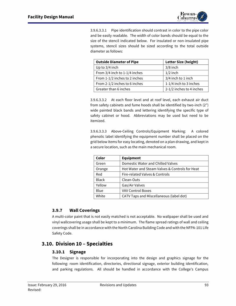
Facility Design Manual
Issue: February 29, 2016 Revisions and Updates 93
Revised:
3.9.6.3.3.1 Pipe identification should contrast in color to the pipe color
and be easily readable. The width of color bands should be equal to the
size of the stencil indicated below. For insulated or non-insulated pipe
systems, stencil sizes should be sized according to the total outside
diameter as follows:
Outside Diameter of Pipe Letter Size (height)
Up to 3/4 inch 3/8 inch
From 3/4 inch to 1-1/4 inches 1/2 inch
From 1-1/2 inches to 2 inches 3/4 inch to 1 inch
From 2-1/2 inches to 6 inches 1-1/4 inch to 3 inches
Greater than 6 inches 2-1/2 inches to 4 inches
3.9.6.3.3.2 At each floor level and at roof level, each exhaust air duct
from safety cabinets and fume hoods shall be identified by two-inch (2”)
wide painted black bands and lettering identifying the specific type of
safety cabinet or hood. Abbreviations may be used but need to be
itemized.
3.9.6.3.3.3 Above-Ceiling Controls/Equipment Marking: A colored
phenolic label identifying the equipment number shall be placed on the
grid below items for easy locating, denoted on a plan drawing, and kept in
a secure location, such as the main mechanical room.
Color Equipment
Green Domestic Water and Chilled Valves
Orange Hot Water and Steam Valves & Controls for Heat
Red Fire-related Valves & Controls
Black Clean-Outs
Yellow Gas/Air Valves
Blue VAV Control Boxes
White CATV Taps and Miscellaneous (label dot)
3.9.7 Wall Coverings
A multi-color paint that is not easily matched is not acceptable. No wallpaper shall be used and
vinyl wallcovering usage shall be kept to a minimum. The flame spread ratings of wall and ceiling
coverings shall be in accordance with the North Carolina Building Code and with the NFPA-101 Life
Safety Code.
3.10. Division 10 – Specialties
3.10.1 Signage
The Designer is responsible for incorporating into the design and graphics signage for the
following: room identification, directories, directional signage, exterior building identification,
and parking regulations. All should be handled in accordance with the College’s Campus
Facility Design Manual
Issue: February 29, 2016 Revisions and Updates 94
Revised:
Standards. All signage to be APCO, Model “Arcadia”; Designer to coordinate details with the
Owner. The Designer is responsible for developing compatible graphics for any required
applications not addressed by the signage program, such as “YOU ARE HERE” maps, including
emergency egress routes.
3.10.1.1 Exterior: All should be handled in accordance with the College’s Campus
Standards.
3.10.1.2 Building Interior: All spaces, including custodial, mechanical, and closet
spaces, shall have assigned numbers and appropriate signage.
3.10.1.3 Wayfinding signage will be installed to provide direction to spaces in large
buildings.
3.10.1.4 Egress maps will be provided as required by Code in frames which allow
periodic updates of the graphics. During phased occupancy of any building, egress signage
will be updated with each change to egress.
3.10.2 Room Numbering
It is desirable that the construction numbering system be retained throughout the life of the
facility. Numbering systems will be coordinated with the Division of Facilities Services. The
following are general guidelines for space numbering in all buildings:
3.10.2.1 Designers are to submit and receive written approval of the “Room Numbering
Plan” from the Division of Facilities Services prior to establishing final base plans. The
Designer, therefore, is to submit a numbering system with the Schematic Design submittal.
The Construction Documents for all design disciplines shall display the approved,
permanent room number assignments.
3.10.2.2 The numbering system shall use three-digit numbers with alpha suffixes, if
necessary; four digit numbers are not acceptable. Suites can be numbered with nested
letters, such as 243-A, 243-B, 243-C, etc.
3.10.2.3 Number sequence shall progress continuously in a corridor, generally moving
clockwise around the building. Using odd or even numbers on either side of the corridor is
neither required nor desired. Where corridor configurations make it impossible for a
continuous numerical progression, the Designer shall strive to achieve a logical numerical
progression.
3.10.2.4 The numbering system shall provide spare numbers in the sequencing,
especially where there are large rooms or open spaces where future renovations could
subdivide the space.
3.10.2.5 All spaces are to be assigned room numbers (closets, elevators, janitorial
rooms, lobbies, rest rooms, stairs, vestibules, etc.). Lobbies will not have signage.
3.10.2.6 The lowest floor with a primary entrance shall be assigned “100” series
Facility Design Manual
Issue: February 29, 2016 Revisions and Updates 95
Revised:
numbers. All other floors above 100 shall be labeled 200, 300 series, etc. All floors located
below grade shall be assigned numbers with “B” prefix (B02, B03, etc.).
3.10.3 Toilet Compartments
The preferred partition for toilet compartment is floor-mounted, overhead-braced type. Provide
one foot (1’-0”) clearance from floor to partition for cleaning. Use stainless steel or phenolic plastic
partition material. Provide one (1) coat hook for each stall.
3.10.4 Toilet and Bath Accessories
All toilet accessories shall be stainless steel with satin finish, unless otherwise noted. Toilet and
bath accessories shall be provided as follows:
3.10.4.1 Framed Mirrors: One piece roll-formed frame heavy gauge, stainless steel
angle with satin finish. Frame shall be continuous integral stiffener on all sides for added
strength. Corners shall be welded, ground, and polished smooth. The mirror shall be one-
quarter inch (1/4”) polished plate glass mirror, electrolytically copper plated.
3.10.4.2 Toilet Tissue Dispensers: Provide one (1) nine-inch (9”) double-roll, stainless
steel toilet paper dispenser unit per toilet stall.
3.10.4.3 Paper Towel Dispensers: Semi-recessed, surface-mounted, touch-free paper
towel dispensers will be furnished by the current vendor for the College. Provide one (1)
dispenser in each single-fixture toilet room.
3.10.4.4 Electric Hand Dryers: Provide one (1) electric hand dryer per two (2) sinks in
each multi-fixture toilet room. Hand dryers to be a designed system that includes a stainless
steel plate, or other wall guard, to protect against damage to grout and paint from water
evaporation.
3.10.4.5 Soap Dispensers: Touch-free, battery operated liquid soap dispensers to be
furnished by the current vendor for the College. Provide one (1) liquid soap dispenser per
two (2) sinks.
3.10.4.6 Trash Cans: Provide 13-20 gallon, semi-recessed trash receptacle with
removable trash container.
3.10.5 Fire Extinguishers & Cabinets
Designers shall clearly identify locations for fire extinguishers and cabinets on the plans. Locations
shall be planned with the intent to provide appropriate coverage, while having the least
interference with the interior design. Finish of Cabinets to be selected and coordinated with the
Interior Design palette.
3.10.5.1 Install 10-12 pound ABC type fire extinguishers in semi-recessed fire
extinguisher cabinets as required.
3.10.5.2 Install CO2 fire extinguishers in hazardous areas and in mechanical room areas.
Facility Design Manual
Issue: February 29, 2016 Revisions and Updates 96
Revised:
3.10.5.3 Install BC rated type fire extinguishers in cooking areas.
3.10.6 Automatic Electronic Defibrillators (AEDs) & Cabinets
Designers shall clearly identify locations for automatic electronic defibrillators and cabinets on
the plans. Locations shall be planned with the intent to provide appropriate coverage, while
having the least interference with the interior design.
3.10.6.1 Install AEDs in AED Cabinets as required.
3.10.6.2 AED Cabinets shall be grouped with fire extinguisher cabinets. Cabinets should
coordinate in appearance and finish.
3.10.6.3 AED Cabinets will be equipped with an audible alarm which activates when the
door is opened. Cabinet design should allow for visual inspection of the AED unit inside.
3.10.7 Wall Protection
Use corner guards fabricated of type 304 (18-8), 18-gauge stainless steel with exposed surfaces in
architectural satin finish. Exposed edges and corners to be rounded, with adhesive strips for
permanent installation. Use Bradley Corporation Model 991-48.
3.11. Division 11 – Equipment
3.11.1 Parking Control
Parking Control equipment shall be provided to match the existing campus standard equipment.
See also Section 3.20 Division 28 – Electronic Safety and Security.
3.11.1.1 Entrance gates will have their own power supply and the opener will be
provided with a contact that will open the gate. The gate will close when it senses that the
car has passed.
3.11.1.2 Exit gates will have their own power supply and a sensing device that will open
the gate when a car approaches from the parking lot side and another sensing device that
will close the gate once the car has passed.
3.11.1.3 At the gate island, provide a campus standard card reader ten to twelve feet
(10-12’) before the gate.
3.11.1.4 Provide 3/4” conduit at the gate island to run from the gate opener housing on
a direct path to the control equipment. The length of the conduit should be less than one
hundred feet (100’).
3.11.1.5 Provide a 3/4” conduit from the gate opener housing to the edge of the curb
for the entrance and exit gates. This conduit will be used for the sensor wire placed in the
pavement so the curb will not be cut.
Facility Design Manual
Issue: February 29, 2016 Revisions and Updates 97
Revised:
3.11.2 Trash Compactors
Trash compactors shall have a six feet, six inches (6’-6”) by six feet, six inches (6’-6”) by six feet (6’-
0”) feet deep (8 cubic yards/6.1 cubic meters) trash holder with compactor located on top, such as
the Vert-I-Pack (VIP) unit by Marathon.
3.11.2.1 A ten feet (10’-0”) wide by twelve feet (12’-0”) high overhead coiling door shall
be provided for truck access. Controls will be provided on the interior and exterior and
should be equipped with a remote control. The control on the exterior of the building shall
have a key control that can activate the pushbuttons.
3.11.2.2 A ventilation fan shall be provided in the compactor area along with a hose bib
and a place to store a hose, mop, and broom. The floor shall slope to a twelve inch by twelve
inch (12”x12”) drain with a minimum of six to eight inch (6”-8”) drain pipe to the sanitary
sewer system.
3.11.2.3 The temperature of the trash room shall be a minimum of 40 degrees F.
3.11.3 Recycle Equipment
Every building shall provide adequate space for recycling waste material. This space shall be
exclusively for the storage of recycling equipment and recyclable material, in addition to a
container for general trash. Recycle closets are not recommended. The guidelines for content is
as follows:
3.11.3.1 Exterior: Allocate space adjacent to exterior dumpster for an eight (8) cubic
yard “cardboard only” dumpster.
3.11.3.2 Interior: Allocate space on each primary floor of the building for a grouping of
five (5) recycle containers; one each for office paper, newspaper, magazines, plastic
bottles/aluminum cans, and glass.
3.11.3.3 Public Sidewalks: Provide a plastic bottle/aluminum can container adjacent to
general trash container. See Section 3.12 for Site Furnishings.
3.11.4 Dumpsters
Dumpsters for trash and cardboard recycling to be furnished by the vendor for the College.
Dumpsters to be 8 cubic yards in size, with a notched front.
3.11.5 Vending Equipment
3.11.5.1 If required by the building program, the Designer shall coordinate the
requirements for all vending equipment with the RCCC Food Services Department.
3.11.5.2 Vending machines should be located as to minimize noise transference to
other areas of the facility. This may include placing machines in a room or alcove.
3.11.5.3 Vending machines produce heat which will damage the food products. Heat
buildup in the area must be vented to the outside.
Facility Design Manual
Issue: February 29, 2016 Revisions and Updates 98
Revised:
3.12. Division 12 – Furnishings
3.12.1 Entrance Floor Mats and Fames
Entrance floor mats and frames shall be provided inside each entrance to the building. These mats
shall be of the type which is removable for cleaning and should be of exterior quality. Recesses
shall be of even footage sizes to accommodate factory stocked mats.
3.12.1.1 Provide Cobblestone, Arrowhead, Kara Mat, or Protector heavy duty
wiper/scraper 3/8” thickness pile. Constructed from fifty (50) ounces of 100% polypropylene
per square yard, using a blend of heavy denier fibers coated for superior mat performance,
level loop pile, or V-Loop double-needled. Backing composed of a non-skid rubber, coated
with a fire retardant latex for maximum safety; and carries a three year warranty.
3.12.2 Site Furnishings
Site furnishings are listed as follows:
3.12.2.1 Exterior Trash Receptacles
Victor Stanley, Inc., Ironsite Series
Model: SD-42 36
Description: 36-Gallon side opening with standard tapered formed lid.
Color: Victor Stanley Green (typical).
3.12.2.2 Exterior Tables
DuMor Site Furnishings
Model: 76-44PLR
Description: 4’ square, 4 seat pedestal table, 4”x4” “redwood” recycled plastic slats. Table
can be ground mounted [S1] or surface mounted [S2].
Color: PC Green.
3.12.2.3 Exterior Benches
DuMor Site Furnishings
Model: 88-60PLR
Description: 6’ bench, surface plates, “redwood” recycled plastic slats. Table Bench can be
ground mounted [S1] or surface mounted [S2].
Color: PC Green.
3.12.2.4 Bike Racks
Madrax Trilary, Inc.
Model: HW238
Description: Heavy Duty Winder, loop, surface flange, powder coat finish. Racks are
available in 5 loop (7 bikes), 7 loop (9 bikes), and 11 loop (13 bikes).
Color: Forest Green.

Facility Design Manual
Issue: February 29, 2016 Revisions and Updates 99
Revised:
3.13. Division 13 – Special Construction (Not Used)
3.14. Division 14 - Conveying Equipment
3.14.1 Elevators
Elevators shall comply with all current State guidelines and regulations for College buildings and
State-owned facilities. Elevator to be selected based on building height and required use.
Hydraulic elevators and machine room-less elevators will be considered. Cargo elevators will be
provided as required (i.e. Advanced Technology Center, etc.).
3.14.1.1 Elevator Passenger Car
3.14.1.1.1 Each passenger car shall be equipped with an exhaust fan (2-speed),
emergency lighting supply, handrails on the walls, security camera, and emergency
telephone cabinet (see Section 3.19 Division 27 Communications). All equipment
and finishes shall be vandal resistant.
3.14.1.1.2 Size car and door for building equipment and furniture. Provide taller
cabs in Dormitory buildings to accommodate larger furniture.
3.14.1.1.3 Ceilings of the car shall not invite vandalism. Provide vandal-proof
fixtures and ceiling installation (i.e. gypsum board with access panel(s) or ACT with
hold-down clips).
3.14.1.1.4 Flooring shall be vinyl tile flooring for most applications.
3.14.1.1.5 Walls shall be scratch-resistant laminate for heavy abuse areas and
furnished with removable wall pads and hangers.
3.14.1.1.6 All doors and exposed trim shall be stainless steel.
3.14.1.1.7 Braille plates and signage shall be high quality zinc die cast braille and
shall meet all ADA and ANSI requirements.
3.14.1.1.8 Each car shall contain a lighted floor indicator above the car door or
in the return column; soffit mounting is not acceptable.
3.14.1.1.9 Elevator door safety system shall protect passengers by setting up a
harmless curtain of infrared beams.
3.14.1.1.10 Each car control panel shall have a “keyed switch” to take the elevator
out of service, keyed to the College keying system.
3.14.1.2 Elevator Fixtures & Equipment
3.14.1.2.1 Elevator Controls Modernization System shall be a microprocessor-
based network with improved performance over relay-based or conventional
dispatching systems. The system shall have the capability of real time
management and advance information processing to analyze building traffic
patterns and evaluates estimated times of arrival (ETA) based on car position and

Facility Design Manual
Issue: February 29, 2016 Revisions and Updates 100
Revised:
hall call assignments for each car in the building. The system shall dispatch the car
with the shortest ETA so passenger wait time is minimal.
3.14.1.2.2 Electrical Car Position Indicator shall be provided in the upper portion
of the elevator cab. An audible signal shall sound prior to elevator arriving at, or
passing, any landing.
3.14.1.2.3 Car Riding Lantern shall be provided with a fixture mounted in the
jamb, or soffit, of the elevator cab entrance to notify waiting passengers by means
of electrically illuminated direction arrows and audible gong as to which direction
the elevator will be traveling.
3.14.1.2.4 Door Hold-Open Timer shall be a modification to the elevator control
circuitry combined with a solid state timer which is wired to the door open button
in the elevator car.
3.14.1.2.5 Corridor Hall Stations shall be surface mounted and have a modular
design to allow for quick and easy installation of all components, including key
switches, etched instructions, and signage. Hall stations shall be made of anodized
aluminum in stainless tones and mirror finished in frame.
3.14.1.3 Elevator Hoistway
3.14.1.3.1 Where the equipment is subject to loud or sudden vibrations, sound-
deadening material shall be provided to isolate sounds and vibrations from the
supporting floor or wall.
3.14.1.3.2 A hoistway door unlocking device shall be installed at all landings.
One emergency door key for each elevator shall be furnished to the RCCC Physical
Plant.
3.14.1.4 Elevator Machine Rooms
3.14.1.4.1 Provide smoke detectors in all elevator machine rooms, using
ionization detectors for the traction type and photoelectric detectors for the
hydraulic type.
3.14.1.4.2 Smoke detectors in the elevator machine room and each elevator
lobby shall be on a separate zone.
3.15. Division 21 - Fire Suppression (DRAFT – to be completed by others)
3.15.1 Automatic Sprinkler Systems
Automatic sprinkler systems shall be provided as follows:
3.15.1.1 Fire protection systems shall be designed in accordance with the requirements
of NFPA.
Facility Design Manual
Issue: February 29, 2016 Revisions and Updates 101
Revised:
3.15.1.2 Fire protection systems shall comply with all current regulations for State-
owned facilities.
3.15.1.3 Dry pipe systems shall be used anywhere that freezing conditions may occur.
The minimum pipe size in a dry pipe system is one-and-one-quarter inch (1-1/4”).
3.15.1.4 Specify that sprinkler heads be centered in ceiling tiles.
3.15.1.5 Fire Department connections shall be on the street side of buildings and shall
be located and arranged so that hose lines can be readily and conveniently attached to
inlets.
3.15.1.6 Fire protection and domestic waterlines should be designed with parallel lines
and separate shut-off valves to each building.
3.16. Division 22 – Plumbing (DRAFT – to be completed by others) All piping shall be routed as to remain clear of transformer vaults, refrigerated spaces, electrical rooms,
elevator shafts, data and telecommunication rooms, or other critical areas, and vault spaces over
same.
No piping except soil, waste, or drain piping shall be installed in, or below, concrete slabs on grade.
All main piping shall have accessible shut-off valves for isolation purposes. All branch piping from main
shall have isolation shut-off valves.
3.16.1 Domestic Water Piping
Domestic Water piping related items shall be provided as follows:
3.16.1.1 Water piping inside the building and above grade shall be Type L hard drawn
copper.
3.16.1.2 Water piping inside the building and below slab shall be Type K soft annealed
copper tubing with no joints below the slab. Water service shall be stubbed above floor as
near the exterior wall as practical, rather than running below slab to an interior space.
3.16.1.3 Cold water and hot water plumbing piping is not permitted in exterior walls,
except to supply hose bibs.
3.16.1.4 Hose bibs shall be provided in all mechanical equipment rooms, kitchens,
rooms that require wash down, and rooms with floor drains. All hose bibs shall be provided
with vacuum breakers. Frostproof hose bibs shall be used in the exterior walls of all
buildings.
3.16.2 Sanitary Sewer Waste & Vent Piping
Sanitary sewer waste and vent piping related items shall be provided as follows:
Facility Design Manual
Issue: February 29, 2016 Revisions and Updates 102
Revised:
3.16.2.1 Sanitary sewer piping shall be PVC.
3.16.2.2 Vent piping shall be PVC.
3.16.2.3 Drain, waste, and vent piping for acid waste systems shall be of high silicon
cast iron, borosilicate glass (above grade only), or polypropylene piping.
3.16.2.4 Roof drain leaders above grade shall be PVC. All roof drain piping below grade
shall be PVC.
3.16.2.5 Undersides of roof drains and horizontal storm water drains or roof leaders
inside the building shall be insulated to prevent the formation of condensation.
3.16.2.6 Floor drains connected to the sanitary sewer shall be provided in all
mechanical equipment rooms, custodial closets, toilet rooms, and locker rooms.
3.16.2.7 Infrequently used drains shall have traps resealed by a trap primer from clear
water fixtures.
3.16.2.8 Drain lines at exterior stairwells shall be a minimum of four inches (4”) with a
twelve inch (12”) square drain well and grate-type cover.
3.16.3 Back-Flow Prevention Devices
Back-flow prevention devices shall be installed in all buildings, sprinkler systems, and make-up
water lines in accordance with the EPA Safe Water Act. They shall be installed in the mechanical
rooms where they are accessible for testing and maintenance. Tank-type vehicles filling from the
RCCC water supply shall have back-flow prevention devices.
3.16.4 Water Meters
Water meters shall be installed for all buildings in accordance with the State of North Carolina and
local water service provider regulations. Water meters shall be touch-read, have a 1,000-gallon
multiplier, and be easily accessible for reading and maintenance.
3.16.5 Grease Traps
Grease traps shall be installed in accordance with state and local regulations for food service
facilities. Floor drains serving food service areas are required to flow into a grease trap.
3.16.6 Plumbing Fixtures
Plumbing fixtures shall be designed to reduce water consumption. Designers should consider the
following when specifying fixtures:
3.16.6.1 Automated controls in public spaces.
3.16.6.2 Low flow toilets with a siphon jet.
3.16.6.3 Dual flush water closets.
Facility Design Manual
Issue: February 29, 2016 Revisions and Updates 103
Revised:
3.16.6.4 Waterless urinals.
3.16.6.5 Low flow faucets and shower heads.
3.16.6.6 Energy Star rated fixtures and appliances.
3.16.7 Drinking Fountains & Water Coolers
Drinking fountains and water coolers shall be wall-hung, semi-recessed type and Accessible. At
least one water fountain in each building shall be equipped with a bottle filling station.
3.17. Division 23 - Heating, Ventilation, and Air Conditioning (DRAFT –
to be completed by others)
3.17.1 Mechanical Design Requirements
3.17.1.1 Maintainability: Mechanical systems and systems components shall be
durable and easy to maintain. The Designer shall incorporate into equipment and system
design sufficient access and clearance for maintenance, repairs, and replacement.
Incorporate instrumentation necessary for balance and initial adjustment, as well as for
service and monitoring.
3.17.1.2 Reliability: Systems shall have a high degree of reliability. If an entire building
system will be affected by lesser reliability of a component (for example, a pump serving
building chilled water system), then a redundant piece of equipment shall be provided to
increase overall system reliability.
3.17.1.3 Accessibility: All serviceable equipment (fans, valves, reheat coils, VAV boxes,
clean-outs, junctions, etc.) to be installed behind an inaccessible finished surface shall be
made accessible by the installation of suitable access doors. All equipment provided shall
be accessible either from the exterior or by elevator.
3.17.1.4 Design Conditions: All mechanical systems and equipment should be designed
based on the ASHRAE Climate Recommendations for Rowan and Cabarrus Counties.
3.17.1.5 Energy Conservation: The energy efficiency of building systems and equipment
is an essential part of the College’s design philosophy. Any new project shall be designed
with state-of-the-art energy efficiency. Design standards published by the American
Institute of Architecture (AIA), American Society of Heating Refrigeration and Air
Conditioning Engineers (ASHRAE), and the State of North Carolina shall be met or exceeded.
3.17.1.5.1 Major energy consuming systems and equipment shall be specified
and purchased based on Life Cycle Cost Analysis. All projects ten thousand (10,000)
square feet or larger shall require a Life Cycle Cost Analysis.
3.17.1.5.2 Building functions that require twenty-four hour a day operation,
Facility Design Manual
Issue: February 29, 2016 Revisions and Updates 104
Revised:
such as libraries, laboratories, computer rooms, and others as identified by the
College, shall be served by a system separate from that of offices or classrooms that
are subject to different operating schedules.
3.17.1.5.3 Economizer Cycle that allows the use of outdoor air for free cooling
during the winter and intermediate seasons without the use of mechanical
refrigeration equipment shall be provided. The Designer shall provide heat
recovery for all systems using one hundred percent (100%) outdoor air with both a
supply and return air fan. In addition, careful attention should be given to
designing a system in which the air stream is properly blended.
3.17.1.5.4 All mechanical systems shall be controlled by a direct connection to
the building automation system.
3.17.1.5.5 Three-phase electric motors for mechanical equipment shall be
specified to be premium efficiency and a service factor of 1.0
3.17.1.5.6 The Designer shall use variable volume air handling systems and
variable volume pumping to optimize energy efficiency. Fans and pumps shall be
selected with the highest efficiency available. Wire-to-water efficiency shall be
evaluated for pumps, prior to making the final selection.
3.17.1.5.7 The thickness of insulation for chilled water, hot water, steam, and
condensate shall be geared toward conserving energy. Insulation thickness shall
be selected for optimum cost versus efficiency.
3.17.1.5.8 Cooling towers shall be selected with motors equipped with variable
frequency drives to allow for energy efficient capacity control. Hydronic systems
shall be designed with two-way valves to prevent energy waste.
3.17.1.5.9 The Designer shall evaluate mechanical systems energy efficiency not
only at full load, but also at partial load conditions. The Designer shall submit a
report indicating energy use for new facilities expressed in BTUs per square foot
per year. The total energy consumption shall indicate monthly use of electricity,
steam, water, cooling, heating, and gas.
3.17.1.6 Commissioning: Commissioning will be provided by an independent, third-
party consulting agency. The commissioning agent will be responsible for ensuring that
building systems perform in accordance with the design intent and the College’s
operational needs. The College considers the following elements as a minimum
requirement for building acceptance:
3.17.1.6.1 Installation Verification
3.17.1.6.2 Startup and Checkout
3.17.1.6.3 Performance Testing and Demonstration
Facility Design Manual
Issue: February 29, 2016 Revisions and Updates 105
Revised:
3.17.2 Sound and Vibration Control
Sound and vibration shall not produce noise levels that will be objectionable to facility occupants.
The Designer will specify the dB level required to meet this goal.
3.17.2.1 HVAC equipment located in the building shall be carefully evaluated for sound
level. If sound levels are expected to be higher than recommended in ASHRAE guidelines,
sound control devices are required.
3.17.2.2 In general, all larger air-handling units will require sound attenuation in
ductwork downstream from the fan for both the supply and return. Some mechanical
equipment rooms might require lightweight acoustic materials for walls to isolate
equipment noise from the rest of the building.
3.17.2.3 Acoustic lining is not an acceptable standard for duct systems.
3.17.2.4 Air noise from a supply outlet is not acceptable.
3.17.2.5 There shall be no objectionable transmission of vibration from equipment to
the building structure.
3.17.2.6 Mechanical Equipment Rooms shall be placed preferably at ground level and
away from occupied spaces to minimize transmission of vibrations and noise into the
building.
3.17.3 Piping Insulation
3.17.3.1 The Designer shall evaluate thermal insulation properties and moisture
migration to prevent surface condensation.
3.17.3.2 Adequate protection for underground piping against ground water and
electrolytic forces shall be provided.
3.17.3.3 All valves and fittings shall be insulated with preformed fitting insulation.
3.17.4 Piping and Valves
3.17.4.1 Appropriate devices for piping expansion shall be provided.
3.17.4.2 The Designer shall provide for a positive means of draining and venting piping
systems. Valves shall be provided to allow for isolation of branch piping and risers.
3.17.4.3 Balancing valves shall be provided to facilitate system testing and balancing.
3.17.4.4 Pressure taps on each flow measuring device shall be extended outside of the
insulation.
3.17.4.5 Butterfly valves shall be of the positive shut-off type.
Facility Design Manual
Issue: February 29, 2016 Revisions and Updates 106
Revised:
3.17.5 Pumps & Pump Systems
3.17.5.1 Pumps shall have a minimum clearance of twenty-four inches (24”) on sides
and end of pumps and motors to allow access for service and repair.
3.17.5.2 Pumps shall have isolation valves to allow pumps to be removed and repaired.
3.17.5.3 Pumps shall have bleed valves and gauge ports at accessible locations.
3.17.5.4 All pumps shall be serviceable without removing the volute from piping
connections.
3.17.5.5 Pumps use considerable amounts of energy. Select pumps with the highest
efficiency available for the particular application.
3.17.5.6 Pumps shall be installed in mechanical equipment rooms.
3.17.5.7 Outdoor pump installation shall be avoided. Pump packages should be
avoided.
3.17.6 Chilled Water Systems
3.17.6.1 The desired cooling medium for air conditioning systems is chilled water. For
new construction and renovation projects, the Designer shall verify that the existing chilled
water system will support the new load.
3.17.6.2 The Designer shall consider using a water side economizer to meet winter
cooling loads in applications where the use of 100 percent (100%) outdoor air for free
cooling is not possible. Plate, frame, shell, or tube heat exchangers are strongly
recommended for this application.
3.17.7 Boilers
Where individual boilers are required:
3.17.7.1 Gas-fired, stainless steel condensing, forced draft boilers will be utilized.
3.17.7.2 Electric boilers are not acceptable.
3.17.7.3 Temperature reset controls will be utilized on hot water systems.
3.17.7.4 Provide sensors on hot water supply and return.
3.17.8 Refrigeration Equipment
Preference shall be given to chilled water production based on water-cooled centrifugal chillers.
Trane is the current “Owner Preferred Alternate” for chiller equipment on campus. Other options
may be considered if circumstances warrant and are approved by the College.
Generally, the Designer shall select water-cooled reciprocating or rotary chillers for cooling loads
up to 190 tons. For cooling loads 200 tons and up, centrifugal chillers shall be specified.
Facility Design Manual
Issue: February 29, 2016 Revisions and Updates 107
Revised:
3.17.8.1 Air-cooled equipment shall be used for small renovation projects where
physical limitations preclude the use of chilled water.
3.17.8.2 Provide environmentally safe refrigerants that conform to the latest
Environmental Protection Agency and OSHA requirements.
3.17.8.3 Ventilation of all mechanical rooms with refrigeration equipment shall be
provided. Ventilation shall be accessible for activation from an emergency switch located
outside any of the mechanical room access doors. Mechanical room ventilation shall be
negative to corridor or any other adjacent spaces.
3.17.9 Cooling Towers
3.17.9.1 Cooling towers shall be located in such a way as to have sufficient
unobstructed space to allow for adequate air supply for tower fans. Care shall be taken to
prevent possible air recirculation.
3.17.9.2 Cooling tower location shall be as near as practical to level conditions and as
close as possible to the chillers and pumps to minimize pumping costs.
3.17.9.3 Tower locations shall be as far as possible from trees and other foliage.
Screens shall be provided on tower intakes to keep debris and leaves out of tower sump.
3.17.9.4 Balancing valves at hot water basins, extended lube lines, and stainless steel
cold water basins are required.
3.17.9.5 Noise level shall be an important consideration in the selection of cooling
towers. Cooling towers shall be selected with motors equipped with variable frequency
drives to allow for energy efficient capacity control.
3.17.9.6 A hose bib shall be provided at each cooling tower for cleaning.
3.17.9.7 Chemical testing shall be provided by a third-party consulting agency.
3.17.10 Air Handling Units
3.17.10.1 The use of multi-zone air handling units, spray coil systems, and ceiling-
mounted fan coil units is not acceptable in new construction. For small renovation projects,
an exception can be made, if the need is substantiated.
3.17.10.2 Air handling units that use one hundred percent (100%) outdoor air shall be
equipped with preheat, cooling, and reheat coils with individual sensors to allow
dehumidification control. Return air shall be ducted.
3.17.10.3 Supply air for the building should be designed for control by duct static
pressure. Return air for the building should be controlled by the building static pressure.
3.17.11 Ductwork
3.17.11.1 Ductwork for air distribution shall be designed to yield minimum owning and
Facility Design Manual
Issue: February 29, 2016 Revisions and Updates 108
Revised:
operating costs by keeping the static and dynamic pressure levels of a duct as low as
possible given the building’s normal physical constraints.
3.17.11.2 The Designer shall provide ductwork that is free of heat gains or losses and
excessive sound levels, has fire and smoke control, and in which air leakage does not exceed
two to five percent (2-5%).
3.17.11.3 To allow for proper system balancing, all branch ducts shall be equipped with
balancing dampers.
3.17.11.4 Variable air volume (VAV) boxes should be provided to adjust temperature
demands on a space. Reheat coils should be located downstream of VAV boxes. Sensors
should be provided where air is discharged.
3.17.11.5 Parallel fans are preferred for fan-powered boxes.
3.17.11.6 The use of flexible ductwork should be avoided. The maximum length of a
flexible duct shall not exceed five feet (5’). Avoid offsets and curves in flexible duct
connections to diffusers and other terminal devices.
3.17.11.7 Provide factory-built access doors large enough to allow service and
inspection of control dampers, reheat coils, humidifiers, fire dampers, and all applicable
system components. The minimum width for access doors will be twenty-four inches (24”).
Doors shall have phenolic labels attached identifying the equipment for which they provide
access.
3.17.11.8 All spaces should include both cooling and heating. Cooling only is not
acceptable due to causing humidity issues.
3.17.11.9 All ductwork in unconditioned spaces shall be provided with vapor-retarding
finish.
3.17.12 Building Automation System
3.17.12.1 Johnson Controls “Metasys” is the “Owner-Preferred Alternate” for Building
Automation Systems (BAS).
3.17.12.2 The Designer shall provide building automation system drawings with the
construction drawings. Copies shall be provided to the RCCC Physical Plant, with no
exception. The drawings shall clearly indicate the design and sequence of operation.
3.17.12.3 If humidity is a specific issue to be controlled in the design of a space, this
information should be clearly communicated on the BAS drawings.
3.17.12.4 The control system shall be fully compatible with the existing Campus
Facilities Automated Controls System.
3.17.12.5 The new system shall have full control capability through the existing server.
All systems must be programmable.
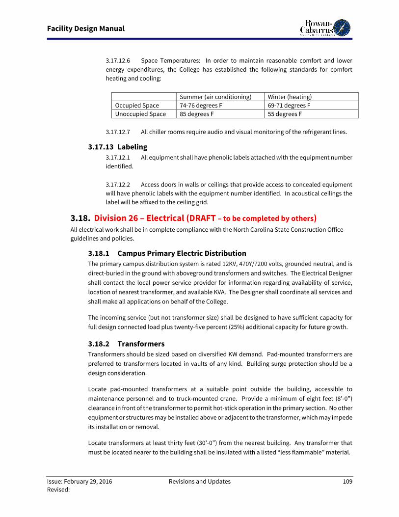
Facility Design Manual
Issue: February 29, 2016 Revisions and Updates 109
Revised:
3.17.12.6 Space Temperatures: In order to maintain reasonable comfort and lower
energy expenditures, the College has established the following standards for comfort
heating and cooling:
Summer (air conditioning) Winter (heating)
Occupied Space 74-76 degrees F 69-71 degrees F
Unoccupied Space 85 degrees F 55 degrees F
3.17.12.7 All chiller rooms require audio and visual monitoring of the refrigerant lines.
3.17.13 Labeling
3.17.12.1 All equipment shall have phenolic labels attached with the equipment number
identified.
3.17.12.2 Access doors in walls or ceilings that provide access to concealed equipment
will have phenolic labels with the equipment number identified. In acoustical ceilings the
label will be affixed to the ceiling grid.
3.18. Division 26 – Electrical (DRAFT – to be completed by others) All electrical work shall be in complete compliance with the North Carolina State Construction Office
guidelines and policies.
3.18.1 Campus Primary Electric Distribution
The primary campus distribution system is rated 12KV, 470Y/7200 volts, grounded neutral, and is
direct-buried in the ground with aboveground transformers and switches. The Electrical Designer
shall contact the local power service provider for information regarding availability of service,
location of nearest transformer, and available KVA. The Designer shall coordinate all services and
shall make all applications on behalf of the College.
The incoming service (but not transformer size) shall be designed to have sufficient capacity for
full design connected load plus twenty-five percent (25%) additional capacity for future growth.
3.18.2 Transformers
Transformers should be sized based on diversified KW demand. Pad-mounted transformers are
preferred to transformers located in vaults of any kind. Building surge protection should be a
design consideration.
Locate pad-mounted transformers at a suitable point outside the building, accessible to
maintenance personnel and to truck-mounted crane. Provide a minimum of eight feet (8’-0”)
clearance in front of the transformer to permit hot-stick operation in the primary section. No other
equipment or structures may be installed above or adjacent to the transformer, which may impede
its installation or removal.
Locate transformers at least thirty feet (30’-0”) from the nearest building. Any transformer that
must be located nearer to the building shall be insulated with a listed “less flammable” material.
Facility Design Manual
Issue: February 29, 2016 Revisions and Updates 110
Revised:
Where use of a pad-mounted transformer is not feasible, underground vaults are discouraged.
Every effort should be made to provide adequate space for a vault in the building, located where
it is readily accessible and where there is no danger of flooding. The vault should not be located
under or opposite the building entrance. In addition to the necessary maintenance access
requirements, provisions should be made for possible removal of equipment from the vault.
Doors, window openings, or removable panels in walls should be considered so that large
equipment can be removed without structural, piping, or lighting changes. Water, steam, vent, or
drain pipes of any kind are not permitted in the transformer vault, switchgear room, or
switchboard room. Switchgear should be locate in a separate room so that it is not subject to high
ventilation rates in vaults.
3.18.3 Emergency Generators
Emergency generators should be located in weather-protected space contiguous with the building
which the generator serves. Generator exhaust should be routed to discharge above the roof and
remote from any air intake for the building. Standard clearances shall be provided to access
panels for maintenance.
3.18.4 Electrical Device Manufacturers
The following electrical device manufacturers are preferred due to compatibility with existing
materials:
3.18.4.1 Panelboards: Westinghouse, GE, I-T-E (Gould), Square D, Siemens-Allis. All
equipment and devices shall be labeled on the panel.
3.18.4.2 Conduit (Steel): Armco Steel, National Steel, Republic Steel, Triangle, Wheeling
Steel, Youngstown Sheet & Tube, Allied Tube & Conduit, Wheatland.
3.18.4.3 Liquidtight Conduit: American Brass, Columbia Cable & Electric, International
Metal Hose.
3.18.4.4 Outlet Boxes: Appleton Electric, General Electric, National Electric Products,
Steel City, Thomas and Betts.
3.18.4.5 Cable Supports: OZ Electric.
3.18.4.6 Insulating Bushings: OZ Electric.
3.18.4.7 Conduit Bodies and Fittings: Appleton Electric, Crouse-Hinds, Thomas and
Betts, Steel City. Only compression type couplings should be provided.
3.18.4.8 Wire and Cable: Anaconda, Cerro de Pasco, General Cable, GE, Kerite, Phelps
Dodge, Rome Cable, Triangle Conduit and Wire, Okonite.
3.18.4.9 Solderless Connectors and Lugs: Burndy, Thomas and Betts, Dosert, OZ
Electric.
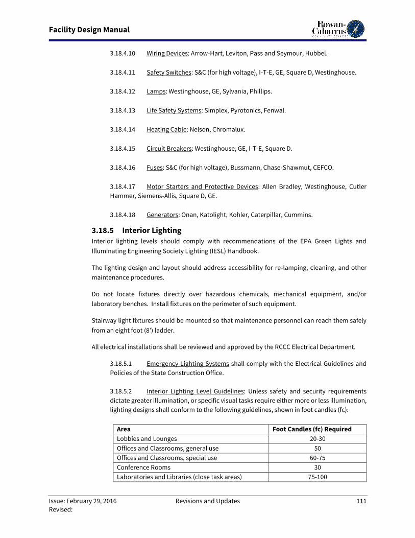
Facility Design Manual
Issue: February 29, 2016 Revisions and Updates 111
Revised:
3.18.4.10 Wiring Devices: Arrow-Hart, Leviton, Pass and Seymour, Hubbel.
3.18.4.11 Safety Switches: S&C (for high voltage), I-T-E, GE, Square D, Westinghouse.
3.18.4.12 Lamps: Westinghouse, GE, Sylvania, Phillips.
3.18.4.13 Life Safety Systems: Simplex, Pyrotonics, Fenwal.
3.18.4.14 Heating Cable: Nelson, Chromalux.
3.18.4.15 Circuit Breakers: Westinghouse, GE, I-T-E, Square D.
3.18.4.16 Fuses: S&C (for high voltage), Bussmann, Chase-Shawmut, CEFCO.
3.18.4.17 Motor Starters and Protective Devices: Allen Bradley, Westinghouse, Cutler
Hammer, Siemens-Allis, Square D, GE.
3.18.4.18 Generators: Onan, Katolight, Kohler, Caterpillar, Cummins.
3.18.5 Interior Lighting
Interior lighting levels should comply with recommendations of the EPA Green Lights and
Illuminating Engineering Society Lighting (IESL) Handbook.
The lighting design and layout should address accessibility for re-lamping, cleaning, and other
maintenance procedures.
Do not locate fixtures directly over hazardous chemicals, mechanical equipment, and/or
laboratory benches. Install fixtures on the perimeter of such equipment.
Stairway light fixtures should be mounted so that maintenance personnel can reach them safely
from an eight foot (8’) ladder.
All electrical installations shall be reviewed and approved by the RCCC Electrical Department.
3.18.5.1 Emergency Lighting Systems shall comply with the Electrical Guidelines and
Policies of the State Construction Office.
3.18.5.2 Interior Lighting Level Guidelines: Unless safety and security requirements
dictate greater illumination, or specific visual tasks require either more or less illumination,
lighting designs shall conform to the following guidelines, shown in foot candles (fc):
Area Foot Candles (fc) Required
Lobbies and Lounges 20-30
Offices and Classrooms, general use 50
Offices and Classrooms, special use 60-75
Conference Rooms 30
Laboratories and Libraries (close task areas) 75-100
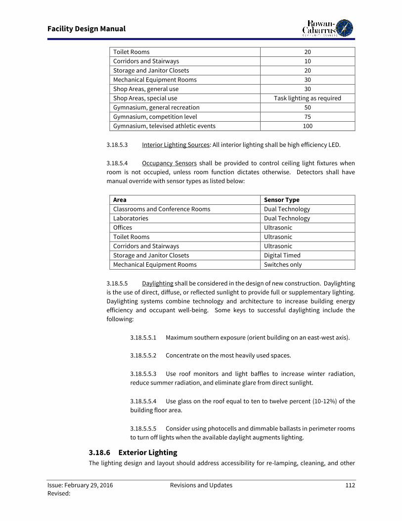
Facility Design Manual
Issue: February 29, 2016 Revisions and Updates 112
Revised:
Toilet Rooms 20
Corridors and Stairways 10
Storage and Janitor Closets 20
Mechanical Equipment Rooms 30
Shop Areas, general use 30
Shop Areas, special use Task lighting as required
Gymnasium, general recreation 50
Gymnasium, competition level 75
Gymnasium, televised athletic events 100
3.18.5.3 Interior Lighting Sources: All interior lighting shall be high efficiency LED.
3.18.5.4 Occupancy Sensors shall be provided to control ceiling light fixtures when
room is not occupied, unless room function dictates otherwise. Detectors shall have
manual override with sensor types as listed below:
Area Sensor Type
Classrooms and Conference Rooms Dual Technology
Laboratories Dual Technology
Offices Ultrasonic
Toilet Rooms Ultrasonic
Corridors and Stairways Ultrasonic
Storage and Janitor Closets Digital Timed
Mechanical Equipment Rooms Switches only
3.18.5.5 Daylighting shall be considered in the design of new construction. Daylighting
is the use of direct, diffuse, or reflected sunlight to provide full or supplementary lighting.
Daylighting systems combine technology and architecture to increase building energy
efficiency and occupant well-being. Some keys to successful daylighting include the
following:
3.18.5.5.1 Maximum southern exposure (orient building on an east-west axis).
3.18.5.5.2 Concentrate on the most heavily used spaces.
3.18.5.5.3 Use roof monitors and light baffles to increase winter radiation,
reduce summer radiation, and eliminate glare from direct sunlight.
3.18.5.5.4 Use glass on the roof equal to ten to twelve percent (10-12%) of the
building floor area.
3.18.5.5.5 Consider using photocells and dimmable ballasts in perimeter rooms
to turn off lights when the available daylight augments lighting.
3.18.6 Exterior Lighting
The lighting design and layout should address accessibility for re-lamping, cleaning, and other
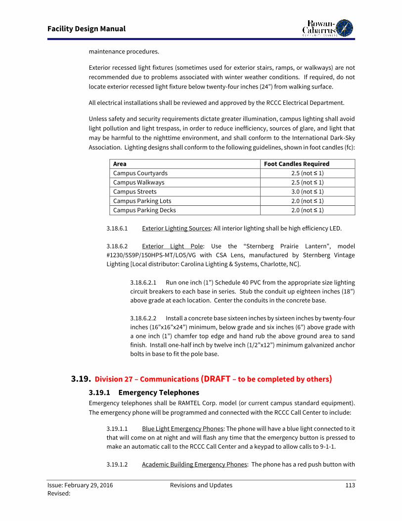
Facility Design Manual
Issue: February 29, 2016 Revisions and Updates 113
Revised:
maintenance procedures.
Exterior recessed light fixtures (sometimes used for exterior stairs, ramps, or walkways) are not
recommended due to problems associated with winter weather conditions. If required, do not
locate exterior recessed light fixture below twenty-four inches (24”) from walking surface.
All electrical installations shall be reviewed and approved by the RCCC Electrical Department.
Unless safety and security requirements dictate greater illumination, campus lighting shall avoid
light pollution and light trespass, in order to reduce inefficiency, sources of glare, and light that
may be harmful to the nighttime environment, and shall conform to the International Dark-Sky
Association. Lighting designs shall conform to the following guidelines, shown in foot candles (fc):
Area Foot Candles Required
Campus Courtyards 2.5 (not ≤ 1)
Campus Walkways 2.5 (not ≤ 1)
Campus Streets 3.0 (not ≤ 1)
Campus Parking Lots 2.0 (not ≤ 1)
Campus Parking Decks 2.0 (not ≤ 1)
3.18.6.1 Exterior Lighting Sources: All interior lighting shall be high efficiency LED.
3.18.6.2 Exterior Light Pole: Use the “Sternberg Prairie Lantern”, model
#1230/5S9P/150HPS-MT/LO5/VG with CSA Lens, manufactured by Sternberg Vintage
Lighting [Local distributor: Carolina Lighting & Systems, Charlotte, NC].
3.18.6.2.1 Run one inch (1”) Schedule 40 PVC from the appropriate size lighting
circuit breakers to each base in series. Stub the conduit up eighteen inches (18”)
above grade at each location. Center the conduits in the concrete base.
3.18.6.2.2 Install a concrete base sixteen inches by sixteen inches by twenty-four
inches (16”x16”x24”) minimum, below grade and six inches (6”) above grade with
a one inch (1”) chamfer top edge and hand rub the above ground area to sand
finish. Install one-half inch by twelve inch (1/2”x12”) minimum galvanized anchor
bolts in base to fit the pole base.
3.19. Division 27 – Communications (DRAFT – to be completed by others)
3.19.1 Emergency Telephones
Emergency telephones shall be RAMTEL Corp. model (or current campus standard equipment).
The emergency phone will be programmed and connected with the RCCC Call Center to include:
3.19.1.1 Blue Light Emergency Phones: The phone will have a blue light connected to it
that will come on at night and will flash any time that the emergency button is pressed to
make an automatic call to the RCCC Call Center and a keypad to allow calls to 9-1-1.
3.19.1.2 Academic Building Emergency Phones: The phone has a red push button with
Facility Design Manual
Issue: February 29, 2016 Revisions and Updates 114
Revised:
auto-dial to the RCCC Call Center and a keypad to allow calls to 9-1-1. A red-to-green LED
light will indicate the call has been answered.
3.19.1.3 Elevator Emergency Phones: The phone has a red push button with auto-dial
to the RCCC Call Center.
3.20. Division 28 - Electronic Safety and Security (DRAFT – to be
completed by others)
3.20.1 Alarm and Detection System
The College does not currently require alarm and detections systems in it’s buildings.
3.20.2 Fire Alarm System
All new buildings, shall be installed with 24-hour addressable monitor systems. Alarm systems will
be voice annunciated. Significant renovations (more than 50%) of existing buildings will trigger
the same requirements.
3.20.2.1 The design and layout of Fire Alarm Systems shall comply with all current
regulations for State-owned facilities.
3.20.2.2 Horns and strobes shall be placed no more than thirty to forty feet (30’-40’)
apart so that they can be heard from any location. Horns shall be heard clearly, 15dBA
above the normal ambient level, in bedrooms, living areas, and bathrooms for residence
halls.
3.20.2.3 New systems shall be fully compatible with the master panel.
3.20.2.4 The College shall provide dedicated telephone lines.
3.20.3 Card Reader System
The MR-5 card access reader device (or current campus standard device) and outside phone shall
be placed on the same side and directly outside of the door it is opening.
3.20.3.1 When possible, the right hand door shall be the controlled door.
3.20.3.2 If there is an entry vestibule, the card reader shall be placed inside the
vestibule and control the second inside set of doors. This will provide additional protection
from severe weather conditions.
3.20.3.3 Locate the power supply for the exit device and the access controller in the
nearest electrical or telecommunications room, so it is accessible for maintenance.
3.20.3.4 The controller shall be placed within one hundred feet (100’) of the card access
reader.
Facility Design Manual
Issue: February 29, 2016 Revisions and Updates 115
Revised:
3.20.4 Gate Control System
Restricted access parking and service yards will have vehicle access limited by security gates with
access controls. The gate opener card reader device shall be located in an enclosed area where
the temperature shall be within thirty-two to one hundred degrees Fahrenheit (32-100o F) and the
humidity shall be within thirty to ninety percent (30-90%).
3.20.4.1 The card access reader shall be located ten to twelve feet (10-12’) in front of
the gate so that it is easily accessible from the driver’s side of an automobile window.
3.20.4.2 Locate the power supply for the exit device and the access controller in the
nearest electrical or telecommunications room, so it is accessible for maintenance.
3.20.4.3 The controller shall be placed within one hundred feet (100’) of the card access
reader.
3.21. Division 31 – Earthwork
3.21.1 Excavating
3.21.1.1 General: Excavation is to be unclassified and is to be performed as Authorized
Excavation regardless of type, nature or condition of the material encountered as necessary
to establish the lines and grades to be shown on the drawings. Once subgrade elevations
have been reached, Architect is to inspect and determine suitability of subgrade material
for intended purpose. If unsuitable, additional excavation can proceed the same as
authorized and paid for at the same unit price established in the bid. It is to be stipulated
that excavations beyond the limits needed to establish required grades without the specific
direction of the Architect will be regarded as unauthorized. Unauthorized excavations and
any required remedial work will be at the contractor’s expense. Remove vegetation, debris,
unsatisfactory soil materials, obstructions, and deleterious materials from ground surface
prior to placement of fills. Plow strip, or break up, sloped surfaces steeper than twenty-five
percent (25%) so that fill material will bond with existing surface.
3.21.1.2 Trenches: Excavations shall be the same as that for general site excavation
except that width shall be only to the extent normal for the utility system being installed.
Trench widths and restoration limits, with appropriate details, will be per the plans. For
excavation beyond normal widths, Designer is to define special backfill requirements.
Trenching shall establish bottoms to the required lines and grades such that proper bedding
of the utility can be accomplished in accordance with the material manufacturer’s
recommendations. All trench bottoms are to be maintained dry until properly backfilled
and compacted. All applicable safety codes are to be followed for sheeting, shoring and
side slope requirements. Trench excavations shall be guarded at all times. It is to be
stipulated that if trenches are to be left open while unattended for any reason, or beyond
work hours, they shall be barricaded with orange safety net adequately staked no less than
four (4) feet from the trench edges.
3.21.1.3 Spoil: Excess excavation and material not suitable for backfill and
embankment operations shall be removed from the College with the exception that the
College reserves the right to select and claim up to the first 2,000 cubic yards. It is to be
stipulated that the contractor shall deposit said material, if owner elects, to a location on
Facility Design Manual
Issue: February 29, 2016 Revisions and Updates 116
Revised:
the campus designated by the Owner at no additional cost. Provisions for maintaining
workmen safety within excavations is the sole responsibility of the Contractor.
3.21.2 Backfill
1.1.2.1 General: For Site and Structures: A non-plastic, clean, granular material
composed of sand, fractured rock, or gravel obtained from the
excavation activities or, if necessary, from off-site borrow shall be
provided. The material shall be substantially free of clays, organics
including loam, peats and wooden materials and trash, which may be
compressible. Quality backfill shall also be void of masonry, rubble and
roadway products. Blending of admixtures to improve gradation
uniformity and stability is permissible. Provide laboratory verification
that intended backfill materials are suitable for the intended purpose
and are not in any way contaminated. Backfill materials shall be
generally placed in six-inch (6”) maximum lifts, loose measure when
compacted by heavy equipment. Specify lifts not more than four inches
(4”) in loose depth for material compacted by hand-operated tampers.
Do not place backfill or fill material on surfaces that are muddy, frozen,
or contain frost or ice.
3.21.1.4 Backfill: To avoid subsurface problems during the life of a new building,
particular emphasis must be placed upon the selection of backfill material around the walls
of buildings.
3.21.1.5 Compaction: Control soil and fill compaction, providing minimum percentages
of maximum density, in accordance with ASTM D 1557, specified for each area classification
indicated below:
3.21.1.3.1 Under structures, building slabs and steps, and pavements, compact
top twelve inches (12”) of subgrade and each layer of backfill or fill material at
ninety-five percent (95%) maximum density.
3.21.1.4.2 Under lawn or unpaved areas, compact top six inches (6”) of subgrade
and each layer of backfill or fill material at ninety percent (90%) maximum density.
3.21.1.4.3 Under walkways, compact top six inches (6”) of subgrade and each
layer of backfill or fill material at ninety-five percent (95%) maximum density.
3.21.1.6 Excavation and Backfilling of Utilities Trenches: All trenching and backfilling
work shall conform to the North Carolina Department of Labor, OSHA Trenching, and other
Safety Standards.
3.21.1.4.1 All trenches four feet (4’) and deeper require shoring.
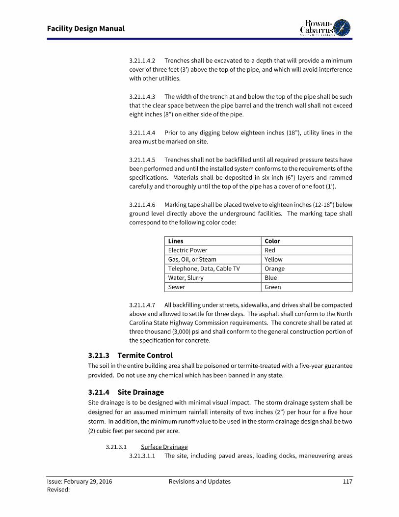
Facility Design Manual
Issue: February 29, 2016 Revisions and Updates 117
Revised:
3.21.1.4.2 Trenches shall be excavated to a depth that will provide a minimum
cover of three feet (3’) above the top of the pipe, and which will avoid interference
with other utilities.
3.21.1.4.3 The width of the trench at and below the top of the pipe shall be such
that the clear space between the pipe barrel and the trench wall shall not exceed
eight inches (8”) on either side of the pipe.
3.21.1.4.4 Prior to any digging below eighteen inches (18”), utility lines in the
area must be marked on site.
3.21.1.4.5 Trenches shall not be backfilled until all required pressure tests have
been performed and until the installed system conforms to the requirements of the
specifications. Materials shall be deposited in six-inch (6”) layers and rammed
carefully and thoroughly until the top of the pipe has a cover of one foot (1’).
3.21.1.4.6 Marking tape shall be placed twelve to eighteen inches (12-18”) below
ground level directly above the underground facilities. The marking tape shall
correspond to the following color code:
Lines Color
Electric Power Red
Gas, Oil, or Steam Yellow
Telephone, Data, Cable TV Orange
Water, Slurry Blue
Sewer Green
3.21.1.4.7 All backfilling under streets, sidewalks, and drives shall be compacted
above and allowed to settle for three days. The asphalt shall conform to the North
Carolina State Highway Commission requirements. The concrete shall be rated at
three thousand (3,000) psi and shall conform to the general construction portion of
the specification for concrete.
3.21.3 Termite Control
The soil in the entire building area shall be poisoned or termite-treated with a five-year guarantee
provided. Do not use any chemical which has been banned in any state.
3.21.4 Site Drainage
Site drainage is to be designed with minimal visual impact. The storm drainage system shall be
designed for an assumed minimum rainfall intensity of two inches (2”) per hour for a five hour
storm. In addition, the minimum runoff value to be used in the storm drainage design shall be two
(2) cubic feet per second per acre.
3.21.3.1 Surface Drainage
3.21.3.1.1 The site, including paved areas, loading docks, maneuvering areas
Facility Design Manual
Issue: February 29, 2016 Revisions and Updates 118
Revised:
adjacent to docks, and landscaped areas, shall be graded in such a manner that
gravity runoff occurs at all points, and all areas shall slope away from the building
on a minimum gradient of one-quarter inch (1/4”) per foot. All terrain surrounding
the building, including loading and parking areas, shall be graded in such a manner
that, if storm drains serving the area become stopped up, water will flow away from
the building.
3.21.3.1.2 The maximum permissible horizontal distance that storm water shall
be permitted to flow over the site before entering a catch basin or other inlet shall
be seventy-five feet (75’). This applies to grassed areas, paved areas, and elevated
parking areas.
3.21.3.1.3 Lawns and mulch areas are encouraged, when possible, around new
building areas to increase natural percolation and decrease impervious runoff.
3.21.3.1.4 Surface drainage shall be directed away from planting areas when
possible. Subsurface drainage may be required in new planting areas with poor
soils.
3.21.3.2 Natural Drainage
3.21.3.2.1 Natural drainage shall be utilized and maintained wherever possible.
3.21.3.2.2 The vegetative area fifty feet (50’) from each side of the centerline of
the swale or stream shall be maintained whenever possible to provide for greater
natural percolation and pollutant filtering.
3.21.3.2.3 When a natural drainage course is required to be diverted due to site
improvements the following shall be considered, the vegetative area adjacent to
the new drainage course shall be replanted to its original condition or improved
with lawn and/or tree plantings.
3.21.3.3 Subsurface Drainage
3.21.3.3.1 An underground storm sewer system shall be provided to
accommodate the roof drainage system.
3.21.3.3.2 The minimum size grate acceptable shall be eight inches (8”) square.
3.21.3.3.3 Drainage grates in lawn areas within twenty-five feet (25’) of a
walkway shall be designed to have a two percent (2%) slope from the edge of the
walk to the storm drainage rim.
3.21.3.3.4 Beehive type drainage grates shall be used in mulched planting areas.
3.21.3.4 Headwalls
3.21.3.4.1 Headwalls shall be veneered stone.
3.21.3.4.2 Slope and creek bed stabilization methods other than riprap should
Facility Design Manual
Issue: February 29, 2016 Revisions and Updates 119
Revised:
be considered.
3.21.3.5 Drain Opening Protection
3.21.3.5.1 Install removable bars or grilles at open end of culverts, drains, and
pipes ten inch (10”) diameter or larger.
3.21.3.5.2 In exterior stairwells, areaways, and similar locations, where leaf
clogging of conventional drains would be expected, provide scupper or dome type
drains.
3.22. Division 32 - Exterior Improvements
3.22.1 Walks, Steps, and Ramps
3.22.1.1 Walks shall be constructed identical to existing walks and of equal widths as
appropriate. Walk surfaces shall be left one inch (1”) above finish grade.
3.22.1.2 Steps should be minimized where possible and replaced with ramps. Steps
shall ideally have a six inch (6”) rise and twelve inch (12”) tread with one-quarter inch (1/4”)
wash across the tread.
3.22.1.3 Ramps shall be constructed on a gradient not to exceed one foot (1’) in twelve
feet (12’) and a minimum of six feet (6’) wide for removal of snow.
3.22.1.4 See Section 3.3 Division 03 – Concrete for concrete requirements and Section
3.4 Division 04 – Masonry for brick pavers.
3.22.2 Asphalt Paving
3.22.2.1 Streets and Driveways with Bus Traffic: Paving shall consist of a minimum of
five inches (5”) of Type HB asphalt base or six inches (6”) of compacted course aggregate,
two inches (2”) of Type H asphalt binder, and two inches (2”) of Type I-2 asphalt surface
course properly crowned to allow for drainage.
3.22.2.2 Parking Lots: Paving shall consist of a minimum of six inches (6”) of coarse
aggregate stone base fully compacted. The surface course shall be Type I-2 asphalt
concrete placed in a minimum thickness of two inches (2”) and properly crowned to allow
for drainage.
3.22.2.3 Curbs and Gutters: All curbs and gutters shall be Portland cement concrete
and shall conform to North Carolina Department of Transportation standards – six inch (6”)
curb and twenty-four inch (24”) gutter.
3.22.3 Landscaping
The campus landscape environment consists of plant materials that form a canopy layer, a focus
layer, and a floor layer. The canopy is an outdoor ceiling that provides unobstructed visual
movement throughout the campus. Collectively, the layers give structure and order to the
campus. The established landscape pattern of canopy trees and lawn should be reinforced and
Facility Design Manual
Issue: February 29, 2016 Revisions and Updates 120
Revised:
maintained.
3.22.3.1 Plant materials are used to:
3.22.3.1.1 Add visual interest to the outdoor environment.
3.22.3.1.2 Accentuate building and campus entrances at eye level.
3.22.3.1.3 Enclose special areas, such as plazas and courtyards.
3.22.3.1.4 Screen unappealing elements, such as dumpsters, service areas, and
parking.
3.22.3.1.5 Control access and circulation.
3.22.3.2 Tree Protection: Prior to the start of construction, any existing trees located
within the proposed construction site are to be evaluated by the RCCC Physical Plant
Landscape Services to determine the location of a safety barrier fence around the root zone
of the trees. At no time is the area directly under the drip line of the tree to be used for
storage or disturbed by machinery. Barrier fencing shall be installed on a radius of at least
eighteen inches (18”) for each inch of trunk diameter [12-inch trunk diameter = 18 feet tree
protection zone radius].
3.22.3.3 Subsoil shall be permeable and shall be brought to a friable condition by
harrowing or otherwise loosening and mixing with mulch (40 bales per acre) to a depth of
at least four inches (4”). Lumps and clods are to be thoroughly broken and stones larger
than four inches (4”) are to be removed.
3.22.3.4 Topsoil shall be stripped from all areas to be graded (either excavated or filled)
and shall be stockpiled during construction. Topsoil shall not be stockpiled under trees. At
the completion of the job, the topsoil shall be spread on the ground around the building to
establish the finish grade. The areas shall be scarified one-and-a-half feet (1.5’) deep and
all construction debris picked out and hauled off before spreading the topsoil. Topsoil shall
be placed in six inch (6”) layers and compacted by normal movement of equipment over
area to a final depth of four inches (4”). After the topsoil is spread, the entire area shall be
left smooth. All debris, roots, and rocks measuring one inch (1”) and larger shall be
removed.
3.21.3.4.1 Topsoil should not exceed the grade which existed prior to
construction.
3.22.3.5 Mulching and Weeding: New planting beds should be weed free and mulched
with two to four inches (2-4”) of hardwood mulch. Individual trees should have a minimum
five foot (5’) diameter circle of hardwood mulch. All mulched areas should be treated with
pre-emergent herbicide at a rate of one hundred fifty pounds (150 lb.) per acre of actual
material, or three pounds (3 lb.) of active ingredient per acre. The finish grade of any
shrubbery beds not planted or mulched, should be three inches (3”) lower than the existing
Facility Design Manual
Issue: February 29, 2016 Revisions and Updates 121
Revised:
finish grade of sidewalks.
3.22.4 Xeriscaping
Xeriscaping promotes water conservation by using drought-tolerant plant materials that thrive in
the environment within a landscape carefully designed for maximum use of rainfall runoff and
minimum care. Xeriscaping principles can significantly reduce water use and save money.
Xeriscaping principles also stress the aesthetics of using native vegetation, reduction in turf, water
harvesting techniques, the use of mulches, and proper maintenance practices.
Buildings shall be landscaped for energy efficiency and water conservation. Bushes and large
trees provide shading and act as a wind break.
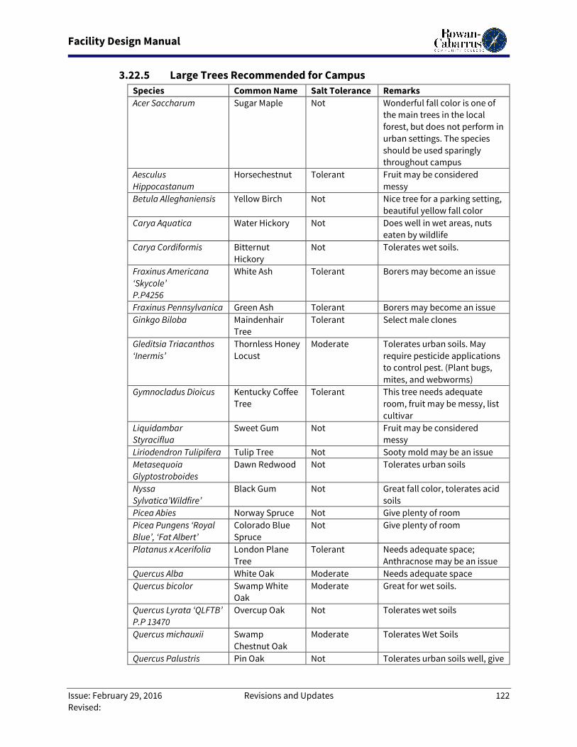
Facility Design Manual
Issue: February 29, 2016 Revisions and Updates 122
Revised:
3.22.5 Large Trees Recommended for Campus
Species Common Name Salt Tolerance Remarks
Acer Saccharum Sugar Maple Not Wonderful fall color is one of
the main trees in the local
forest, but does not perform in
urban settings. The species
should be used sparingly
throughout campus
Aesculus
Hippocastanum
Horsechestnut Tolerant Fruit may be considered
messy
Betula Alleghaniensis Yellow Birch Not Nice tree for a parking setting,
beautiful yellow fall color
Carya Aquatica Water Hickory Not Does well in wet areas, nuts
eaten by wildlife
Carya Cordiformis Bitternut
Hickory
Not Tolerates wet soils.
Fraxinus Americana
‘Skycole’
P.P4256
White Ash Tolerant Borers may become an issue
Fraxinus Pennsylvanica Green Ash Tolerant Borers may become an issue
Ginkgo Biloba Maindenhair
Tree
Tolerant Select male clones
Gleditsia Triacanthos
‘Inermis’
Thornless Honey
Locust
Moderate Tolerates urban soils. May
require pesticide applications
to control pest. (Plant bugs,
mites, and webworms)
Gymnocladus Dioicus Kentucky Coffee
Tree
Tolerant This tree needs adequate
room, fruit may be messy, list
cultivar
Liquidambar
Styraciflua
Sweet Gum Not Fruit may be considered
messy
Liriodendron Tulipifera Tulip Tree Not Sooty mold may be an issue
Metasequoia
Glyptostroboides
Dawn Redwood Not Tolerates urban soils
Nyssa
Sylvatica’Wildfire’
Black Gum Not Great fall color, tolerates acid
soils
Picea Abies Norway Spruce Not Give plenty of room
Picea Pungens ‘Royal
Blue’, ‘Fat Albert’
Colorado Blue
Spruce
Not Give plenty of room
Platanus x Acerifolia London Plane
Tree
Tolerant Needs adequate space;
Anthracnose may be an issue
Quercus Alba White Oak Moderate Needs adequate space
Quercus bicolor Swamp White
Oak
Moderate Great for wet soils.
Quercus Lyrata ‘QLFTB’
P.P 13470
Overcup Oak Not Tolerates wet soils
Quercus michauxii Swamp
Chestnut Oak
Moderate Tolerates Wet Soils
Quercus Palustris Pin Oak Not Tolerates urban soils well, give
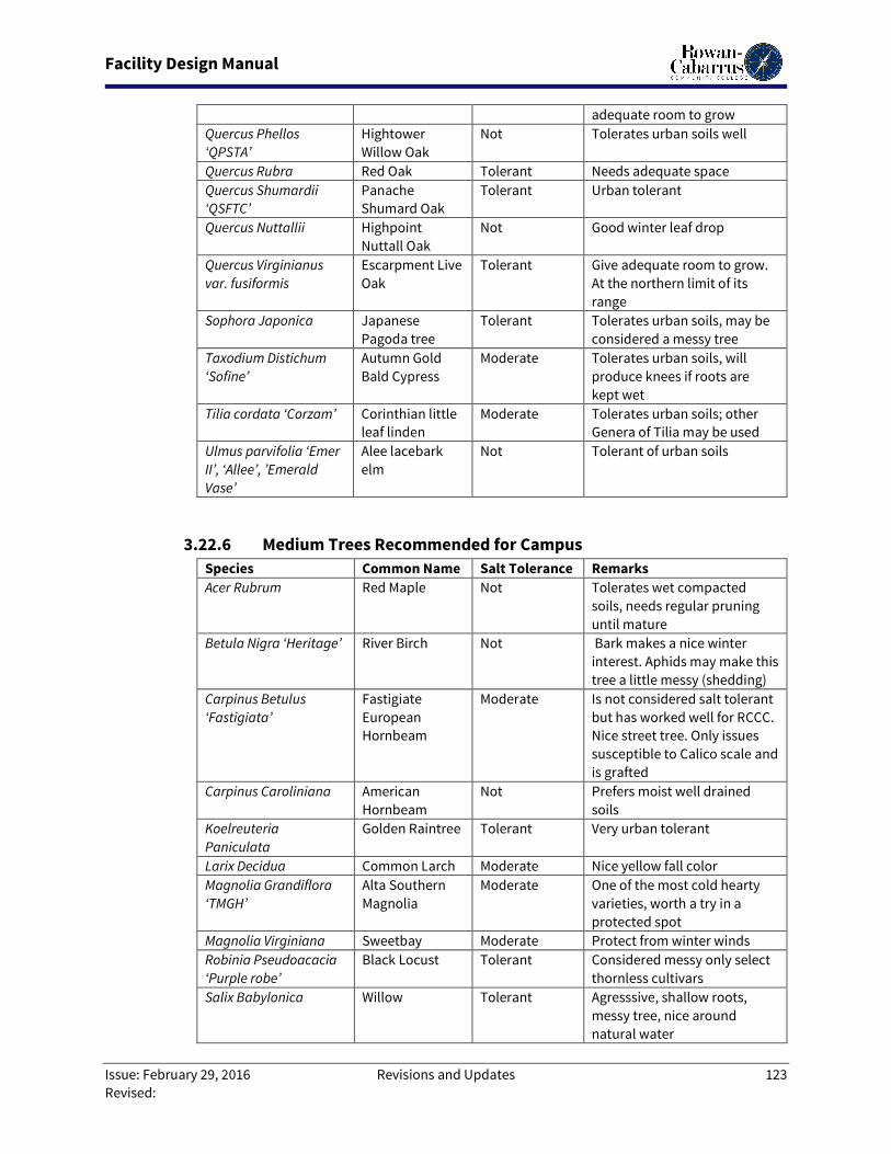
Facility Design Manual
Issue: February 29, 2016 Revisions and Updates 123
Revised:
adequate room to grow
Quercus Phellos
‘QPSTA’
Hightower
Willow Oak
Not Tolerates urban soils well
Quercus Rubra Red Oak Tolerant Needs adequate space
Quercus Shumardii
‘QSFTC’
Panache
Shumard Oak
Tolerant Urban tolerant
Quercus Nuttallii Highpoint
Nuttall Oak
Not Good winter leaf drop
Quercus Virginianus
var. fusiformis
Escarpment Live
Oak
Tolerant Give adequate room to grow.
At the northern limit of its
range
Sophora Japonica Japanese
Pagoda tree
Tolerant Tolerates urban soils, may be
considered a messy tree
Taxodium Distichum
‘Sofine’
Autumn Gold
Bald Cypress
Moderate Tolerates urban soils, will
produce knees if roots are
kept wet
Tilia cordata ‘Corzam’ Corinthian little
leaf linden
Moderate Tolerates urban soils; other
Genera of Tilia may be used
Ulmus parvifolia ‘Emer
II’, ‘Allee’, ’Emerald
Vase’
Alee lacebark
elm
Not Tolerant of urban soils
3.22.6 Medium Trees Recommended for Campus
Species Common Name Salt Tolerance Remarks
Acer Rubrum Red Maple Not Tolerates wet compacted
soils, needs regular pruning
until mature
Betula Nigra ‘Heritage’ River Birch Not Bark makes a nice winter
interest. Aphids may make this
tree a little messy (shedding)
Carpinus Betulus
‘Fastigiata’
Fastigiate
European
Hornbeam
Moderate Is not considered salt tolerant
but has worked well for RCCC.
Nice street tree. Only issues
susceptible to Calico scale and
is grafted
Carpinus Caroliniana American
Hornbeam
Not Prefers moist well drained
soils
Koelreuteria
Paniculata
Golden Raintree Tolerant Very urban tolerant
Larix Decidua Common Larch Moderate Nice yellow fall color
Magnolia Grandiflora
‘TMGH’
Alta Southern
Magnolia
Moderate One of the most cold hearty
varieties, worth a try in a
protected spot
Magnolia Virginiana Sweetbay Moderate Protect from winter winds
Robinia Pseudoacacia
‘Purple robe’
Black Locust Tolerant Considered messy only select
thornless cultivars
Salix Babylonica Willow Tolerant Agresssive, shallow roots,
messy tree, nice around
natural water
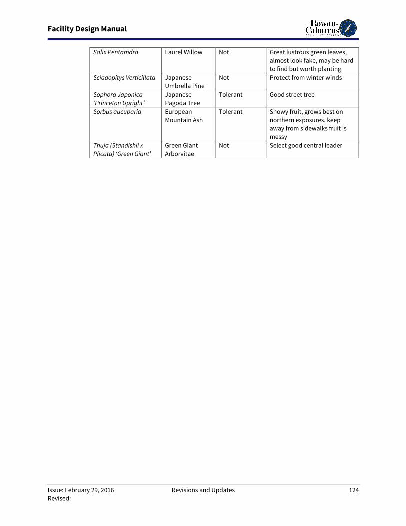
Facility Design Manual
Issue: February 29, 2016 Revisions and Updates 124
Revised:
Salix Pentamdra Laurel Willow Not Great lustrous green leaves,
almost look fake, may be hard
to find but worth planting
Sciadopitys Verticillata Japanese
Umbrella Pine
Not Protect from winter winds
Sophora Japonica
‘Princeton Upright’
Japanese
Pagoda Tree
Tolerant Good street tree
Sorbus aucuparia European
Mountain Ash
Tolerant Showy fruit, grows best on
northern exposures, keep
away from sidewalks fruit is
messy
Thuja (Standishii x
Plicata) ‘Green Giant’
Green Giant
Arborvitae
Not Select good central leader
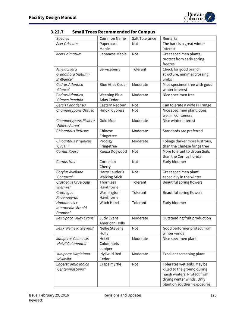
Facility Design Manual
Issue: February 29, 2016 Revisions and Updates 125
Revised:
3.22.7 Small Trees Recommended for Campus
Species Common Name Salt Tolerance Remarks
Acer Griseum Paperback
Maple
Not The bark is a great winter
interest
Acer Palmatum Japanese Maple Not Great specimen plants,
protect from early spring
freezes
Amelachier x
Grandiflora ‘Autumn
Brilliance’
Serviceberry Tolerant Check for good branch
structure, minimal crossing
limbs
Cedrus Atlantica
‘Glauca’
Blue Atlas Cedar Moderate Mice specimen tree with good
winter interest
Cedrus Atlantica
‘Glauca Pendula’
Weeping Blue
Atlas Cedar
Moderate Nice specimen tree
Cercis Canadensis Eastern Redbud Not Can tolerate a wide PH range
Chamaecyparis Obtusa Hinoki Cypress Not Nice specimen plant, does
well in containers
Chamaecyparis Pisifera
‘Filifera Aurea’
Gold Mop Moderate Nice winter interest
Chioanthus Retusus Chinese
Fringetree
Moderate Standards are preferred
Chioanthus Virginicus
‘CVSTF’
Prodigy
Fringetree
Moderate Foliage darker more lustrous,
than the Chinese fringe tree
Cornus Kousa Kousa Dogwood Not More tolerant to Urban Soils
than the Cornus florida
Cornus Mas Cornelian
Cherry
Not Early bloomer
Corylus Avellana
‘Contorta’
Harry Lauder’s
Walking Stick
Not Great specimen plant
especially in the winter
Crataegus Crus-Galli
‘Inermis’
Thornless
Hawthorne
Tolerant Beautiful spring flowers
Crataegus
Phaenopyrum
Washington
Hawthorne
Tolerant Beautiful spring flowers
Hamamelis x
Intermedia ‘Arnold
Promise’
Witch Hazel Tolerant Early bloomer
Ilex Opaca ‘Judy Evans’ Judy Evans
American Holly
Moderate Outstanding fruit production
Ilex x ‘Nellie R. Stevens’ Nellie Stevens
Holly
Not Good performer protect from
winter winds
Juniperus Chinensis
‘Hetzii Columnaris’
Hetzii
Columnaris
Juniper
Moderate Nice specimen plant
Juniperus Virginiana
‘Idyllwild’
Idyllwild Red
Cedar
Moderate Excellent screening plant
Lagerstromia Indica
‘Centennial Spirit’
Crape myrtle Not Tolerates wet soils. May be
killed to the ground during
harsh winters. Protect from
drying winter winds. Only
plant on southern exposures.
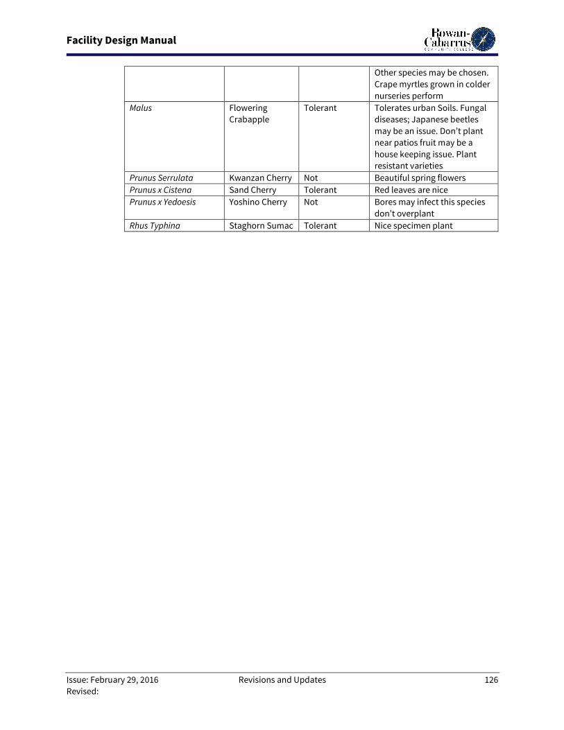
Facility Design Manual
Issue: February 29, 2016 Revisions and Updates 126
Revised:
Other species may be chosen.
Crape myrtles grown in colder
nurseries perform
Malus Flowering
Crabapple
Tolerant Tolerates urban Soils. Fungal
diseases; Japanese beetles
may be an issue. Don’t plant
near patios fruit may be a
house keeping issue. Plant
resistant varieties
Prunus Serrulata Kwanzan Cherry Not Beautiful spring flowers
Prunus x Cistena Sand Cherry Tolerant Red leaves are nice
Prunus x Yedoesis Yoshino Cherry Not Bores may infect this species
don’t overplant
Rhus Typhina Staghorn Sumac Tolerant Nice specimen plant
Facility Design Manual
Issue: February 29, 2016 Revisions and Updates 127
Revised:
3.23. Division 33 – Utilities
3.23.1. Underground Utilities
3.23.3.1. Identification: Contractor is to consult with the Owner and Designer, and
review files to establish a general working knowledge of the extent, type, and probable
locations of all existing utilities. All existing utilities, proposed alterations thereto and new
utilities lines are to be shown on the Civil Site Plans. Contractor to properly notify all
utility service provider and the College directly prior to any digging.
3.23.3.2. Connection to Existing Systems: Any connection to existing utility systems
must first be scheduled with the Facilities Operations & Maintenance Department so
disruption of services is minimized. Contractor is not authorized to operate any valve of
an existing utility system. When needed, such activity is to be requested of the Facilities
Operations & Maintenance Department who will perform the necessary operation. Ample
advanced notice is to be required to schedule this service. Two days is the normal
minimum notice period, but could be longer depending on complexity and extent of
impact on services and operations.
3.23.3.3. Water Distribution:
3.23.3.3.1. Quality Assurance: It is required that all new and relocated water
main pipe, fittings, valves, fire hydrants, and related products that will come into
contact with drinking water be in conformance with the American National Standards
Institute (ANSI)/NSF International Standard 61 and comply with the applicable
American Water Works Association (AWWA) Standards.
3.23.3.3.2. Pipe: Pipe provided is to be Ductile Iron Pipe (DIP) conforming to
ANSI A-21.51 and AWWA C-151. For pipe to be buried, provide Pressure Class 350 for
less than twelve (12) inches and Pressure Class 250 for pipe equal to and larger than
twelve (12) inches. For pipe to be above ground, provide Class 53. The interior of the
pipe shall have a standard thickness cement mortar lining with seal coat conforming
to ANSI A-21.4 and AWWA C104. The exterior is to have a factory applied bituminous or
coal tar varnish coating.
3.23.3.3.3. Fittings: Fittings are to be either cast iron or ductile iron and of a
pressure class compatible with the pipe. Fittings are to also have the same interior
and exterior treatments as required for the pipe.
3.23.3.3.4. Joints: Joints for below grade DIP and fittings shall be push-on or
standard mechanical joint type with rubber gaskets complying with AWWA C111. All
fitting joints and pipe joints below grade where needed shall be mechanically
restrained. Joints for above grade piping shall be flanged.
3.23.3.3.5. Valves:
Facility Design Manual
Issue: February 29, 2016 Revisions and Updates 128
Revised:
3.23.1.3.5.1. Gate Valves: For valves three (3) inches and larger, provide
resilient seat gate valves complying with AWWA C509 such as U.S. Pipe
Metroseal. Minimum working pressure shall be 150 psi. The interior and
exterior shall be epoxy coated in compliance with AWWA C550. Where
installation is below grade, valves are to have a two (2) inch operating nut
housed in a cast iron slip sleeve valve box.
3.23.1.3.5.2. Check Valves: Provide Iron-body, bronze mounted swing
check, horizontal installation conforming to AWWA C508.
3.23.3.3.6. Backflow Preventers: Backflow preventers are to be double check
valve assembly for low hazard applications and reduced pressure (RP) assemblies for
high hazard conditions.
3.23.3.3.7. Water Meters: Each new building service connection shall include an
inline, full flow meter for measuring domestic consumption. The meter is to be ahead
of and coupled with the backflow prevention assembly. The design of the full
assembly is to give due regard to subsequent maintenance operations including ease
of disassembly via use of unions, couplings or other appropriate fittings.
3.23.3.3.8. Water Sampling Ports: For new and extended potable water
distribution systems requiring permit and Health Department clearances, sample
ports shall be provided as required for Code compliance.
3.23.3.4. Sanitary Sewers:
3.23.3.4.1. Quality Assurance: It is required that the design of wastewater
collection and transmission systems be in accordance with the Building Code as well
as any specific requirements of the local utility provider.
3.23.3.4.2. Piping:
3.23.1.4.2.1. Gravity Systems: Gravity sewer piping and fittings are to be
plastic polyvinyl chloride (PVC) conforming to the requirements of ASTM
Designation D3034, SDR-35. Joints for gravity systems are to be push-on
elastomeric gasket type.
3.23.1.4.2.2. Force Mains: For sanitary force mains, provide ductile iron
pipe, DIP, conforming to the requirements of ANSI A21.51 and Class 50. The
pipe and fittings shall have a minimum pressure rating of 150 psi, utilize
standard push-on or mechanical gasket sealed joints and be coated inside
and out with a factory applied bituminous or coal tar epoxy sealant.
3.23.3.4.3. Valves: Valves are to be acid resisting bronze body eccentric plug
valves. The plug shall be resilient (NBR) rubber coated suited for wastewater
applications. Sizes three (3) inches and smaller shall have lever actuators and NPT
connections. Sizes four (4) inches and larger shall have gear reduced handwheel
actuators and be flanged or mechanical joint connected. Below grade installations
shall be placed in a vault.
Facility Design Manual
Issue: February 29, 2016 Revisions and Updates 129
Revised:
3.23.3.4.4. Manholes: Specify manholes to be precast concrete manholes
conforming to ASTM Designation C478. Wall thickness shall be eight (8) and the
bottom barrel section is to be monolithic with the bottom. Pipe connections shall be
made watertight with rubber boots casted integral into the wall sections. Specify an
asphaltic seal coating to be applied to the interior and exterior surfaces. Invert
channels are to be provided to facilitate smooth directional changes in flow.
Manholes to be properly bedded on gravel consisting of crushed granite or blast slag
stone.
3.23.3.5. Storm Water Systems
3.23.3.5.1. Pipe: Stormwater drainage pipe shall be round reinforced concrete
culvert pipe conforming to ASTM Designation C76; reinforced concrete horizontal
elliptical pipe conforming to ASTM Designation C507; HDPE Type II, dual wall
corrugated exterior/smooth interior pipe conforming to ASTM F2648; or, PP, duel wall
corrugated exterior/smooth interior pipe conforming to ASTM F2736, ASTM F2881 and
AASHTO M330 for their respective sizes. The pipe joints for concrete pipe are to be
rubber O-ring gasket type conforming to ASTM C 1628. Specify special bedding
requirements where warranted.
3.23.3.5.2. Structures: Specify stormwater structures at all changes in pipe
direction, points of drainage entry and connection points of branch piping.
Stormwater structures are to be constructed of either precast or cast-in-place
reinforced concrete conforming to ASTM F2648. Where grates are required in bicycle
and pedestrian use areas, stipulate that the grates shall be reticuline steel. Cast iron
grates are to be used in all other areas outside of pedestrian and bicycle ways. When
structures are placed in vehicle use areas, grating, if used, is to be specified as traffic
bearing. Where steel grating is used, it shall be hot dipped galvanized coated.
3.23.3.6. Gas Service: Gas lines to be constructed as shown on the Civil Site Plans to
ensure coordination with other site improvements and prevention of conflict. The
associated work is to be indicated as provided by others on the plans.
3.23.3.7. Hot/Chilled Water: See Section 3.16 - Division 22 Plumbing for specific
requirements regarding piping, valves, fittings, manhole materials, and placement. Site
related mechanical improvements shall be constructed as shown on the Civil Site Plans for
proper coordination with other utilities and resolution of conflicts.
3.23.3.8. Site Electrical: See Section 3.18 - Division 26 Electrical for specific
requirements regarding conduits, cabling, manholes, site lighting, transformers and
switching materials, and placement. Site related electrical improvements shall be
constructed as shown on the Civil Site Plans for proper coordination and resolution of
conflicts.
3.23.3.9. Systems Testing and Connection:
Facility Design Manual
Issue: February 29, 2016 Revisions and Updates 130
Revised:
3.23.3.9.1. Pressure Pipe Installations: All pressure pipe systems are to be
hydrostatically tested to verify integrity of piping materials and installation. Develop
and specify testing procedures consistent with AWWA Standard C600-93. Test
pressures should be set at the rated working pressure of the piping material for a
duration of two (2) hours. Designer is to witness the testing conducted by the
Contractor, record the results in acceptable format, and certify the test results to the
appropriate regulatory authorities for clearance to place the system into service.
3.23.3.9.2. Gravity Pipe Installations: Stipulate that all gravity piping systems
are to be inspected/tested to verify material and material installations are sound and
suitably leak free. Develop infiltration/exfiltration-testing procedures consistent with
respective regulatory requirements. Designer is to witness the testing activities to be
conducted by the Contractor, record the results in acceptable format, and certify the
test results to the appropriate regulatory authorities for clearance to place the system
into service.
3.23.3.9.3. Potable Water System: Where health codes and permits require
bacteriological testing for clearance approval to utilize a new or modified water
system, the Contractor is to provide, setup, and conduct all operations in accordance
with local water utility guidelines, to sterilize, flush, and make the system ready for
sampling and connecting. The Contractor will collect and transport the samples to
the laboratory.
3.23.3.9.4. The Contractor shall ensure that no new or modified system is put
into service until the agency approval/clearance letter has been received.
3.23.3.10. Irrigation:
3.23.3.10.1. Quality Assurance:
3.23.1.10.1.1. Manufacturer Qualification: Provide underground irrigation
system as a complete unit produced by acceptable manufacturer,
including heads, valves, controls, and accessories.
3.23.1.10.1.2. Location of heads shown in Landscaping Plans is
approximate. Make minor adjustments as necessary to avoid plantings
and other obstructions. Do not decrease number of heads indicated
unless otherwise acceptable to Designer.
3.23.3.10.2. Piping and Fittings:
3.23.1.10.2.1. Pressure Pipe: PVC plastic pipe, ASTM D 1785, Schedule 40,
four (4) inches or smaller; four (4) inches or larger Class 200.
3.23.1.10.2.2. Circuit Pipe (downstream from circuit valves): PVC plastic
pipe, ASTM D 1785, Schedule 40, not to be smaller than ¾ inch in size;
reduce if required at the swing joint at the head.
3.23.1.10.2.3. Pipe Fittings: ASTM D 2466 socket fittings with ASTM D 2564
solvent cement.
Facility Design Manual
Issue: February 29, 2016 Revisions and Updates 131
Revised:
3.23.3.10.3. Valves: Automatic Circuit Valves: Glove valves operated by low-
power solenoid, normally closed, manual flow adjustment.
3.23.3.10.4. Sprinkler Heads: Manufacturer’s standard unit designed to provide
uniform coverage over entire area of spray shown on drawings at available water
pressure, as follows:
3.23.1.10.4.1. Pop-Up Spray: Fixed pattern, with screw-type flow
adjustment and stainless steel retraction spring. 1800 series plastic
nozzles shall be used.
3.23.1.10.4.2. Pop-Up Rotary Spray: Gear drive, full circle and adjustable
part-circle type.
3.23.1.10.4.3. Bubblers: Adjustable, point source flooding emitter, on
flexible pipe. Bubblers to be on zone separate from sprays or rotors.
3.23.3.10.5. Valve Box: South Eastern Meter Boxes or equal. Metal box two (2)
inches x ten-and-a-half (10 ½) inches x ten (10) inches (2” x 10-½” x 10”) with a
foundation of cement block or equal. (Carson boxes acceptable.)
3.23.3.10.6. Automatic Control System
3.23.1.10.6.1. General: Furnish low-voltage system manufactured
expressly for control of automatic circuit valves of underground irrigation
system. Provide unit of capacity to suit number of circuits as indicated,
plus 20% extra stations for future use. (Not to exceed 80% of capacity.)
3.23.1.10.6.2. Rain Check: Auto interruption of watering cycle installed on
timing device.
3.23.3.10.7. Trenching and Backfilling:
3.23.1.10.7.1. General: Excavate straight and true with bottom uniformly
sloped to low points.
3.23.1.10.7.2. Minimum Cover: Provide eighteen inches (18”) minimum
cover over top of main and twelve inches (12”) cover over the lateral
piping.
3.23.1.10.7.3. Backfill: Backfill with clean material from excavation.
Remove organic material as well as rocks and debris larger than 1”
diameter. Place acceptable backfill material in 6” lifts, compacting each
lift.
3.23.1.10.7.4. Sleeving: Place sleeves under paving, walkways, and other
obstructions during their construction. Jacking piping under sidewalks
and paving shall only be done where the obstruction pre-exists the
project.
3.23.3.10.8. Installation:
3.23.1.10.8.1. General: Unless otherwise indicated, comply with
requirements of Uniform Plumbing Code.
Facility Design Manual
Issue: February 29, 2016 Revisions and Updates 132
Revised:
3.23.1.10.8.2. Connection to Main: Install a manual valve at every point of
connection to main.
3.23.1.10.8.3. Circuit Valves: Install in valve box, arranged for each
adjustment and removal. A manual valve must be in front of each
automatic valve.
3.23.1.10.8.4. Wiring: Use multi-strand with a separate, 14-gauge neutral.
Maintain a color coded wire to be run in purple or reclaimed water pipe
with electrical type fittings and electrical type junction boxes or valve
boxing.
3.23.1.10.8.5. Electrical Connections: Use recommended weatherproof
type wire connections.
3.23.1.10.8.6. Piping: Lay pipe on solid subbase, uniformly sloped without
humps or depressions. Install PVC pipe in dry weather when temperature
is above 40 degrees F (4 degrees C) in strict accordance with the
manufacturer’s instructions, using purple primer on all pipes and fittings.
Allow joints to cure at least twenty-four (24) hours at temperature above
40 degrees F (4 degrees C) before testing, unless otherwise recommended
by the manufacturer.
3.23.1.10.8.7. Piping not to be within one foot of sidewalks or curbing.
3.23.1.10.8.8. Sprinkler Heads: Flush circuit lines with full head of water
and install after hydrostatic test is completed. Install lawn spray heads at
manufacturer’s recommended heights, using flex pipe. An eighteen inch
(18”) length of flex pipe shall be used for each head to allow adjustments
(swing joint). Locate all heads to maintain a minimum distance of four
inches (4”) from walls and four inches (4”) from other boundaries, unless
otherwise indicated. Exposed spray head risers to be painted dark green.
Install rotor type sprinklers at manufacturer’s recommended heights,
using flex pipe. A twenty-four inch (24”) length of flex pipe shall be used
for each head to allow adjustments (swing joint). Upon completion of
grading, sodding, and rolling of sod areas, carefully adjust lawn sprinkler
heads so they will be flush with, or not more than ½ inch above, finish
grade.
3.23.3.10.9. Testing:
3.23.1.10.9.1. General: Notify Owner or his representative in writing when
testing will be conducted. Conduct tests in Owner’s presence.
3.23.1.10.9.2. Hydrostatic Test: Test water piping and valves before
backfilling trenches to a hydrostatic pressure of not less than 150 PSI.
Piping may be tested in sections to expedite work. Remove and repair
piping, connections, and valves that do not pass hydrostatic testing. Test
pressure must be held for a minimum of two (2) hours.
Facility Design Manual
Issue: February 29, 2016 Revisions and Updates 133
Revised:
3.23.1.10.9.3. Operational Testing: Perform operational testing after
backfill and sod is in place, and sprinkler heads are adjusted to their final
position. Demonstrate to Owner or his representative that system meets
coverage requirements and automatic controls function properly. Provide
drawing to assist in demonstration.
3.23.1.10.9.4. Head to head coverage requirements are based on
operation of one circuit at a time and the GPM of the valve system to
maintain recommended five (5) feet per second. Maintain head-to-head
coverage.
Facility Design Manual
Issue: February 29, 2016 Revisions and Updates 134
Revised:
4. APPENDIX
4.1. Drawings
4.1.1 Classrooms
4.1.1.1 Small
4.1.1.2 Standard
4.1.1.3 Large
4.1.2 Offices
4.1.2.1 President
4.1.2.2 VP/Chief
4.1.2.3 AVP/Supervising Director/Dean
4.1.2.4 Sr. Administrative/Program Chair
4.1.2.5 Open Office Area
4.1.3 Conference Rooms
4.1.3.1 Large Conference Room
4.1.3.2 Medium Conference Room
4.1.3.3 Small Conference Room
4.1.4 Employee Break Room
4.1.5 Work Room