Embed Size (px)
Citation preview

R&D ON STRIPLINES FOR THE CLIC DR KICKERS
C. Belver-Aguilar (IFIC)Acknowledgements: A. Faus-Golfe (IFIC),
F. Toral (CIEMAT), M. Barnes (CERN)
ICFA Beam Dynamics Mini Workshop on Low Emittance Rings 2011 3-5 October 2011 Heraklion, Greece

CLIC Damping
Ring
Beam energy (GeV) 2.86
Total kick deflection angle (mrad) 1.5
Aperture (mm) 20
Effective length (m) 1.7
Field rise time (ns) 1000
Field fall time (ns) 1000
Pulse flattop duration (ns) ~160
Flattop reproducibility ±1x10⁻⁴
Flattop stability [inc. droop], (Inj.)per Kicker SYSTEM (Ext.)
±2x10⁻³
±2x10⁻⁴
Field inhomogeneity (%) [CLIC: 3.5mm radius] [CLIC: 1mm radius]
±0.1 (Inj.)±0.01(Ext.)
Repetition rate (Hz) 50
Pulse voltage per Stripline (kV) ±12.5
Stripline pulse current [50 Ω load] (A) ±250
Longitudinal beam coupling impedance (Ω) < 0.05 ∙ n
Transverse beam coupling impedance (kΩ/m) < 200
INTRODUCTION
Kickers are required to inject beam into and extract beam from the PDR and DR
The CLIC design relies on the presence of PDRs and DRs to achieve the very low
emittance needed.
8 kicker systems will be needed at CLIC PDR and DRs
damping rings reduce beam emittance; hence kickers must be excellent field homogeneity and very low beam coupling impedance

STRIPLINE KICKER OPERATION
BvEqF
qEc
EcEqF 2
Lorentz force over the charged particles of the beam:
for a TEM mode
2 modes of kicker operation: odd and even mode

STRIPLINE KICKER OPERATION
Virtual Ground
+ve
-ve
Beam pipe Ground
Striplines driven to same magnitude, but opposite polarity, voltage, to extract beam ODD mode characteristic impedance.Total capacitance (C) is given by: capacitance between a stripline and virtual ground (C11) capacitance between a stripline and beam-pipe ground (2C12)
+/-ve
+/-ve
Beam pipe Ground
Beam
Same polarity and magnitude of current / voltage induced on both striplines by beam. EVEN mode characteristic impedanceCapacitance (C) is given by: capacitance between a stripline and beam-pipe ground (C11)
C11
C11
2C12
2C12
C11
C11
T1 T2
%01.01
21
T
T
TTT
msT
sT
20
16.2
2
1
only during 0.01% of a period the kicker works out in the odd mode

ODD MODE CHARACTERISTIC IMPEDANCE OPTIMIZATION
STRIPLINE CROSS SECTION: defines the characteristic impedance of the striplines and the homogeneity of the field.
Two types of vacuum chamber have been studied: CYLINDRICAL and RACETRACK vacuum chamber.
easy chamber to be manufactured
better from the beam impedance
point of view
Optimized geometry in order to achieve Z0 = (50 ± 1) Ω and the field homogeneity required
Vacuum chamber Value Electrodes Value
Aperture 20 mm Thickness 4 mm
Radius 55 mm Height 38 mm
Radii 5 mm Edge angle 70°
Edge length 4 mm
Z0o = 49.5 Ω
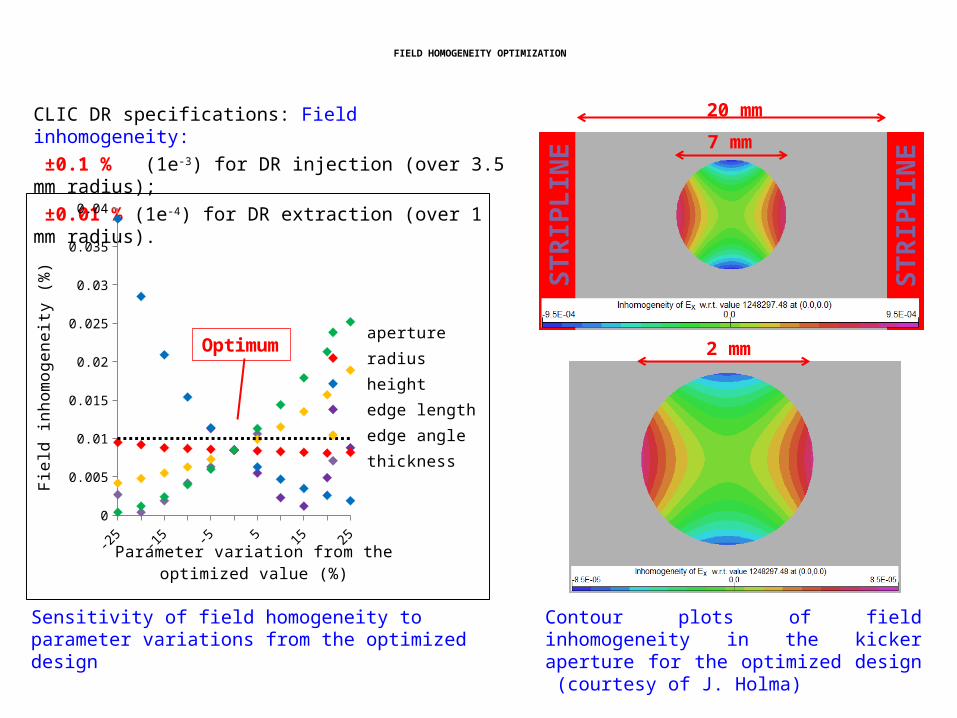
FIELD HOMOGENEITY OPTIMIZATION
CLIC DR specifications: Field inhomogeneity: ±0.1 % (1e-3) for DR injection (over 3.5 mm radius); ±0.01 % (1e-4) for DR extraction (over 1 mm radius).
-25 -20 -15 -10 -5 0 5 10 15 20 250
0.005
0.01
0.015
0.02
0.025
0.03
0.035
0.04
apertureradiusheightedge lengthedge anglethickness
Parameter variation from the optimized value (%)
Fiel
d in
hom
ogen
eity
(%)
Op-timum
Sensitivity of field homogeneity to parameter variations from the optimized design
2 mm
7 mm
20 mm
ST
RIP
LIN
E
ST
RIP
LIN
E
Contour plots of field inhomogeneity in the kicker aperture for the optimized design (courtesy of J. Holma)

BEAM IMPEDANCE OPTIMIZATION: FIRST RESULTS
BEAM IMPEDANCE: defines the interaction of the beam with the kicker, resulting in beam energy lost and a beam shape perturbation.
2
2
////
22
0//
sin
2sinsin2
22
cl
cl
ZZ
c
Li
c
LZZ
tapered
c
Longitudinal beam coupling impedance for untapered (Chao) and tapered stripline kicker (S. Smith, SLAC):
0 / /130 Re_ max( ) 60eZ Z
How can we decrease the longitudinal beam impedance?
Optimizing the kicker geometry in order to achieve 50 Ω even mode characteristic impedance,
L
ll
Thanks to C. Zannini and G. Rumolo who helped me to learn CST Particle Studio.

CONCLUSIONS
• The kicker design for the CLIC DR is presently being studied. By using HFSS simulations the stripline kicker cross section has been optimized in order to obtain the required characteristic impedance and field homogeneity.
• 3D models in CST Particle Studio have been used to study the longitudinal beam impedance. Initial predictions, for both untapered and tapered striplines, compare well with analytical equations.
• The next step will be optimize the geometry of the kicker in order to obtain 50Ω even mode characteristic impedance, as well as the field homogeneity required. In addition it is desirable that the odd mode characteristic impedance, during operation, is as close as possible to 50 Ω.
• Once the new geometry is found, new longitudinal and transverse beam impedance simulations will be carried out. After that, wakefields calculations will be done. These wakefield results will be used for G. Rumolo (CERN), who will study the beam dynamics effects of the kicker.

BIBLIOGRAPHY
• Y. Papaphilippou, Parameter Specification, EDMS 989080, Kickers for the CLIC Damping and Pre-damping Rings, PBS reference: 1.2.-.10.• I. Rodríguez, Calculation Methodology and Fabrication Procedures for Particle Accelerator Strip-line Kickers: application to the CTF3 Combiner Ring Extraction Kicker and TL2 Tail Clippers (2009).• D.M. Pozar, Microwave Engineering. Third Edition.• A. Chao and M. Tigner (Editors), Handbook of Accelerator Physics and Engineering 1998.• S. Smith, SLAC, Private communications.• D. Goldberg, G. Lambertson: Dynamic Devices: A primer on Pickups and Kickers, AIP Conf. Proc. No. 249 (1992).