Embed Size (px)
Citation preview
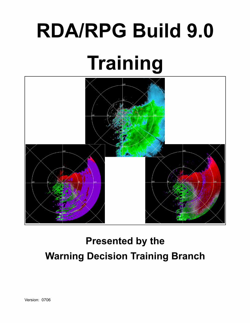
RDA/RPG Build 9.0Training
Presented by the Warning Decision Training Branch
Version: 0706
Warning Decision Training Branch
Overview RDA/RPG Build 9.0 is a software upgrade at theRDA, while at the RPG both the hardware andsoftware are upgraded. This document will presenta summary of the operational impacts ofRDA/RPG Build 9.0 with separate sections on theRDA and the RPG. The RDA impacts will be pre-sented first, with the RPG impacts following.
The Build 9.0 changes at both the RPG and theRDA may impact Unit Radar Committee (URC)decision making. Coordination among URC mem-bers with respect to Build 9.0 URC impacts may benecessary.
RDA Build 9.0Operational
Impacts
The information in the RDA section reflects thepre-deployment state of knowledge of the opera-tional impacts of RDA Build 9.0. Each of the fol-lowing impacts are presented:
1. Change to Gaussian Model Adaptive Process-ing (GMAP) Seed Width Value - page 6
2. Increase in Clutter Filtering Elevation Segments- page 12
3. Sachidananda-Zrnic (SZ)-2 Range UnfoldingAlgorithm - page 19
4. Change To First Displayable Range Bin - page23
RPG Build 9.0Operational
Impacts
The information in the RPG section reflects thepre-deployment state of knowledge of the opera-tional impacts of RPG Build 9.0. Each of the fol-lowing impacts are presented:
1. RPG Refresh - page 242. RPG Human Computer Interface (HCI) Window
Changes - page 253. RPG Impacts of Increase in Clutter Filtering
Elevation Segments at the RDA - page 30
2
RDA/RPG Build 9.0 Training
4. Using the SZ-2 Volume Coverage Patterns(VCPs) - page 33
5. RPG Ingest of Environmental Data from AWIPS- page 44
6. Changes to Mesocyclone Detection Algorithm(MDA) - page 46
7. Snow Accumulation Algorithm (SAA) AdaptableParameter Changes - page 50
8. Machine Intelligent Gust Front Algorithm(MIGFA) - page 52
9. Generation of Cross Sections in VCP 121 -page 52
10.VCP Change or Download Anytime During aVolume Scan - page 52
11.Fix to 1° Radial on Rain and Snow Products -page 53
ObjectivesThe overall goal of the RDA/RPG Build 9.0 trainingis to familiarize NWS forecasters with the opera-tional impacts of this upgrade. The objectives are:
1. Identify the operational impacts of RDA Build9.0 and integrate these impacts into operationalprocedures.
a. Identify the benefit of narrowingthe GMAP Seed Width Value.
b. Identify the benefit of increasingthe number of Clutter FilteringElevation Segments.
c. Identify differences between SZ-2and the legacy Range UnfoldingAlgorithm.
2. Identify the operational impacts of RPG Build9.0 and integrate these impacts into operationalprocedures.
3
Warning Decision Training Branch
a. Identify the overall goal of theRPG Refresh and the resultantchanges to the RPG HCI win-dows.
b. Identify the impact of increasingthe number of Clutter Filter Eleva-tion Segments on the use of clut-ter regions files.
c. Identify the strengths, limitationsand implementation proceduresfor the SZ-2 VCPs.
d. Identify the impacts of RUC dataingest on procedures for updat-ing the Environmental WindsTable and hail temperatureheights.
e. Identify changes to the MDA.f. Identify corrections that affect
cross sections in VCP 121, VCPchanges or downloads, and therain and snow products.
Electronic PerformanceSupport System (EPSS)
The Electronic Performance Support System(EPSS) has been updated to support the Build 9.0changes that are apparent at the RPG HumanComputer Interface (HCI).
Things You Forgot YouKnew?
Understanding the impacts of RDA/RPG Build 9.0requires familiarity with a number of WSR-88Dfunctions and concepts, some of which you maynot have thought about in a long time! The follow-ing will be referenced in this document:
1. Bypass Map Clutter Filtering - A Bypass Mapshould be generated at the RDA for each eleva-tion segment. The map identifies the location(azimuth and range) of clutter targets (targets
4
RDA/RPG Build 9.0 Training
with near zero velocity and narrow spectrumwidth). When clutter filtering within a definedregion is controlled by the Bypass Map, filteringis applied only to the discrete bins identified bythe map.
2. All Bins Clutter Filtering - All Bins is appropriateto address Anomalous Propagation (AP) clutter,which is transient in space and time. When clut-ter filtering within a defined region is controlledby All Bins, filtering is applied to every bin inthat region.
3. Split Cut processing - employed for lower eleva-tion angles for all VCPs except for VCP 121.For each Split Cut elevation, there is first a rota-tion using Contiguous Surveillance (CS) mode,which has a low PRF and a long maximumunambiguous range (Rmax). At the same eleva-tion, there is a second rotation using Contigu-ous Doppler (CD) mode, which has a high PRFand a short Rmax.
4. Batch processing - employed for middle eleva-tion angles for all VCPs except for VCP 31. Thetransmitted signal alternates between low PRFand high PRF mode such that each radial issampled by a certain number of low PRFpulses, then a certain number of high PRFpulses.
5. Doppler Dilemma - there is no single PRF thatmaximizes Rmax and Maximum UnambiguousVelocity (Vmax). For example, the high PRFsnecessary for good quality velocity estimates(high Vmax) also result in a short Rmax.
6. Range Unfolding Algorithm - The high PRFsnecessary for velocity and spectrum width esti-mates result in range folding (multiple trip ech-oes) and overlaid echoes. When echoes areoverlaid, the Range Unfolding Algorithmassigns the appropriate range to a velocity or
5
Warning Decision Training Branch
spectrum width estimate only if its returnedpower is significantly higher than the other(s).
7. Velocity Dealiasing Algorithm - Once velocityestimates are assigned to the appropriaterange, the Velocity Dealiasing Algorithmattempts to unfold any first guess velocities thatare incorrect or aliased.
8. Multiple PRF Dealiasing Algorithm (MPDA) -MPDA is used only with VCP 121. There areextra Doppler rotations at the lower elevationsand the legacy Range Unfolding Algorithmunfolds velocity estimates for each Dopplerrotation. Then MPDA processing performsvelocity dealiasing while providing better avail-ability of velocity estimates (less range foldeddata) due to the extra Doppler rotations.
RDA Build 9.0Operational
Impacts
This section covers the Build 9.0 changes at theRDA. The four changes below may or may notimpact operations at the RPG. For example, thechange to the GMAP seed width is not apparent atthe RPG HCI, while the increase in the number ofelevation segments has a big impact on tasks per-formed at the RPG HCI.
1. Change to GMAP Seed Width Value2. Increase in Clutter Filtering Elevation Segments3. SZ-2 Algorithm4. Change To First Displayable Range Bin
1. Change to GMAP SeedWidth Value
Reference GMAP is the clutter suppression techniqueemployed with the digital Signal Processorrecently installed with the Open RDA (ORDA)upgrade. For a comprehensive overview of GMAPdesign and performance and Build 9.0 improve-
6
RDA/RPG Build 9.0 Training
ments to the clutter filtering process, see “Opti-mizing Clutter Filtering in the WSR-88D”; R.Ice, R. Rhoton, D. Saxion, C. Ray, N. Patel, RSInformation Systems; D. Warde, A. Free, SIInternational; O. Boydstun, D. Berkowitz, J.Chrisman, Radar Operations Center; J. Hub-bert, C. Kessinger, M. Dixon, National Centerfor Atmospheric Research; S. Torres, NationalSevere Storms Laboratory.
This document is available for download from theBuild 9.0 Training web site and the URL will bepresented in the Summary section on page 53.
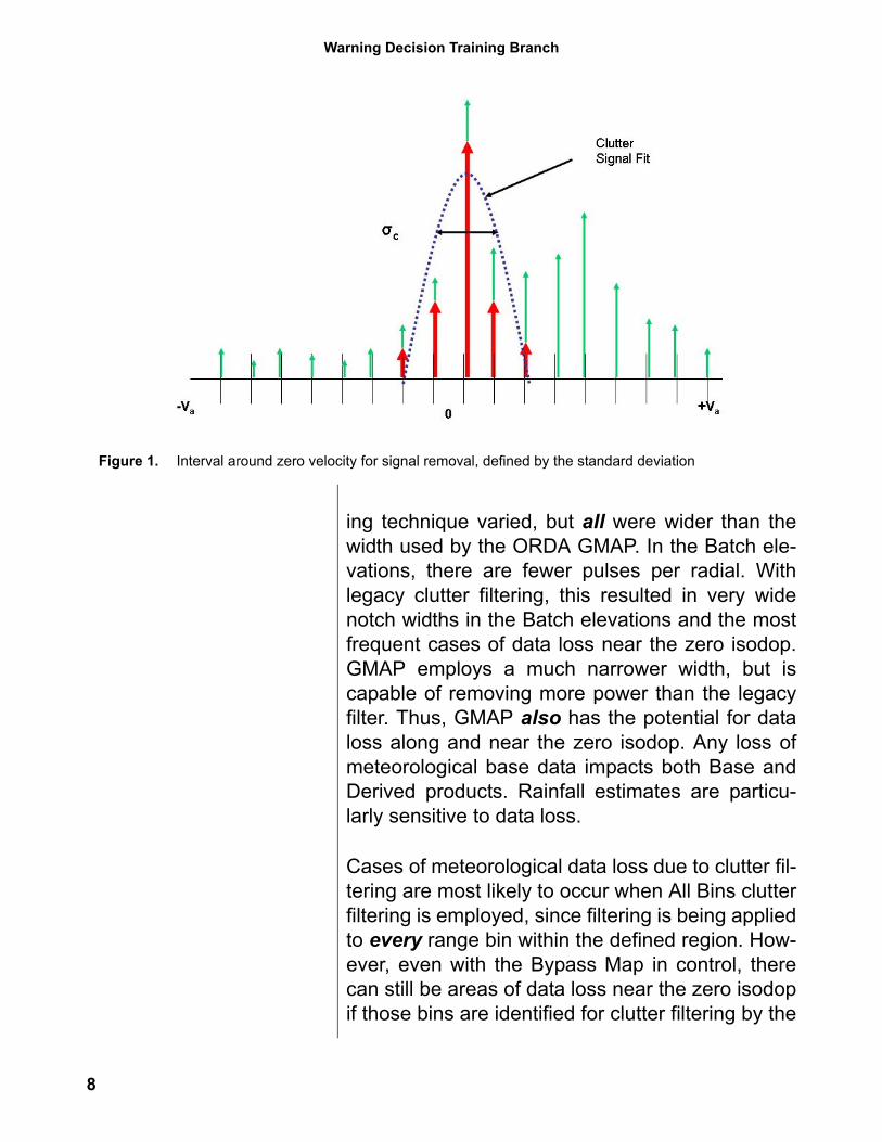
What is Seed Width?The seed width is the initial spectrum width that isused to determine the interval around zero velocityfor clutter signal removal. The seed width is thestandard deviation of the Gaussian curve that is fitto the clutter signal, which is centered at zerovelocity (σc on Figure 1). For the initial deploymentof the ORDA, the seed width was 0.7 m/s or 1.33kts. This width means that the clutter signalremoval would be over a Gaussian curve with astandard deviation (spectrum width) of 1.33 kts.This width defines an interval of ± 0.67 kts aroundzero velocity.
The Build 9.0 GMAP seed width is 0.4 m/s or 0.76kts. This narrower width reduces the standarddeviation (spectrum width) for clutter signalremoval to 0.76 kts. This width defines an intervalof ± 0.38 kts around zero velocity. This narrowerwidth was chosen to help mitigate cases of dataloss.
Why Use a Narrower Seed Width?
There have been cases of clutter filtering removingmeteorological base data along and near the zeroisodop for the life of the WSR-88D. The notchwidths employed with the legacy RDA clutter filter-
7
Warning Decision Training Branch
ing technique varied, but all were wider than thewidth used by the ORDA GMAP. In the Batch ele-vations, there are fewer pulses per radial. Withlegacy clutter filtering, this resulted in very widenotch widths in the Batch elevations and the mostfrequent cases of data loss near the zero isodop.GMAP employs a much narrower width, but iscapable of removing more power than the legacyfilter. Thus, GMAP also has the potential for dataloss along and near the zero isodop. Any loss ofmeteorological base data impacts both Base andDerived products. Rainfall estimates are particu-larly sensitive to data loss.
Cases of meteorological data loss due to clutter fil-tering are most likely to occur when All Bins clutterfiltering is employed, since filtering is being appliedto every range bin within the defined region. How-ever, even with the Bypass Map in control, therecan still be areas of data loss near the zero isodopif those bins are identified for clutter filtering by the
Figure 1. Interval around zero velocity for signal removal, defined by the standard deviation
8

RDA/RPG Build 9.0 Training
Bypass Map. In Figure 2, there is data loss on bothReflectivity and Velocity, south of the radar, alongthe zero isodop. All Bins suppression is beingused at this time.
Figure 3 shows the impact of applying BypassMap suppression a short time later. Note that moredata is available along the zero isodop on bothReflectivity and Velocity.
Figure 2. Data loss along the zero isodop (south of radar) with All Bins suppression applied.
Figure 3. Data loss along the zero isodop (south of radar) mitigated by applying Bypass Map suppression.
9
Warning Decision Training Branch
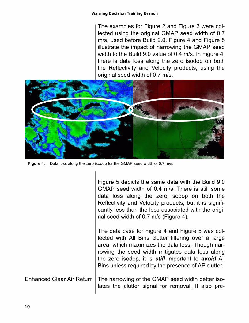
The examples for Figure 2 and Figure 3 were col-lected using the original GMAP seed width of 0.7m/s, used before Build 9.0. Figure 4 and Figure 5illustrate the impact of narrowing the GMAP seedwidth to the Build 9.0 value of 0.4 m/s. In Figure 4,there is data loss along the zero isodop on boththe Reflectivity and Velocity products, using theoriginal seed width of 0.7 m/s.
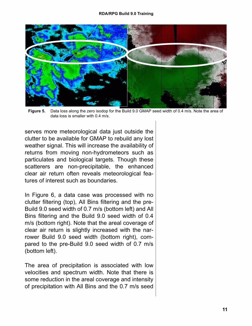
Figure 5 depicts the same data with the Build 9.0GMAP seed width of 0.4 m/s. There is still somedata loss along the zero isodop on both theReflectivity and Velocity products, but it is signifi-cantly less than the loss associated with the origi-nal seed width of 0.7 m/s (Figure 4).
The data case for Figure 4 and Figure 5 was col-lected with All Bins clutter filtering over a largearea, which maximizes the data loss. Though nar-rowing the seed width mitigates data loss alongthe zero isodop, it is still important to avoid AllBins unless required by the presence of AP clutter.
Enhanced Clear Air Return The narrowing of the GMAP seed width better iso-lates the clutter signal for removal. It also pre-
Figure 4. Data loss along the zero isodop for the GMAP seed width of 0.7 m/s.
10
RDA/RPG Build 9.0 Training
serves more meteorological data just outside theclutter to be available for GMAP to rebuild any lostweather signal. This will increase the availability ofreturns from moving non-hydrometeors such asparticulates and biological targets. Though thesescatterers are non-precipitable, the enhancedclear air return often reveals meteorological fea-tures of interest such as boundaries.
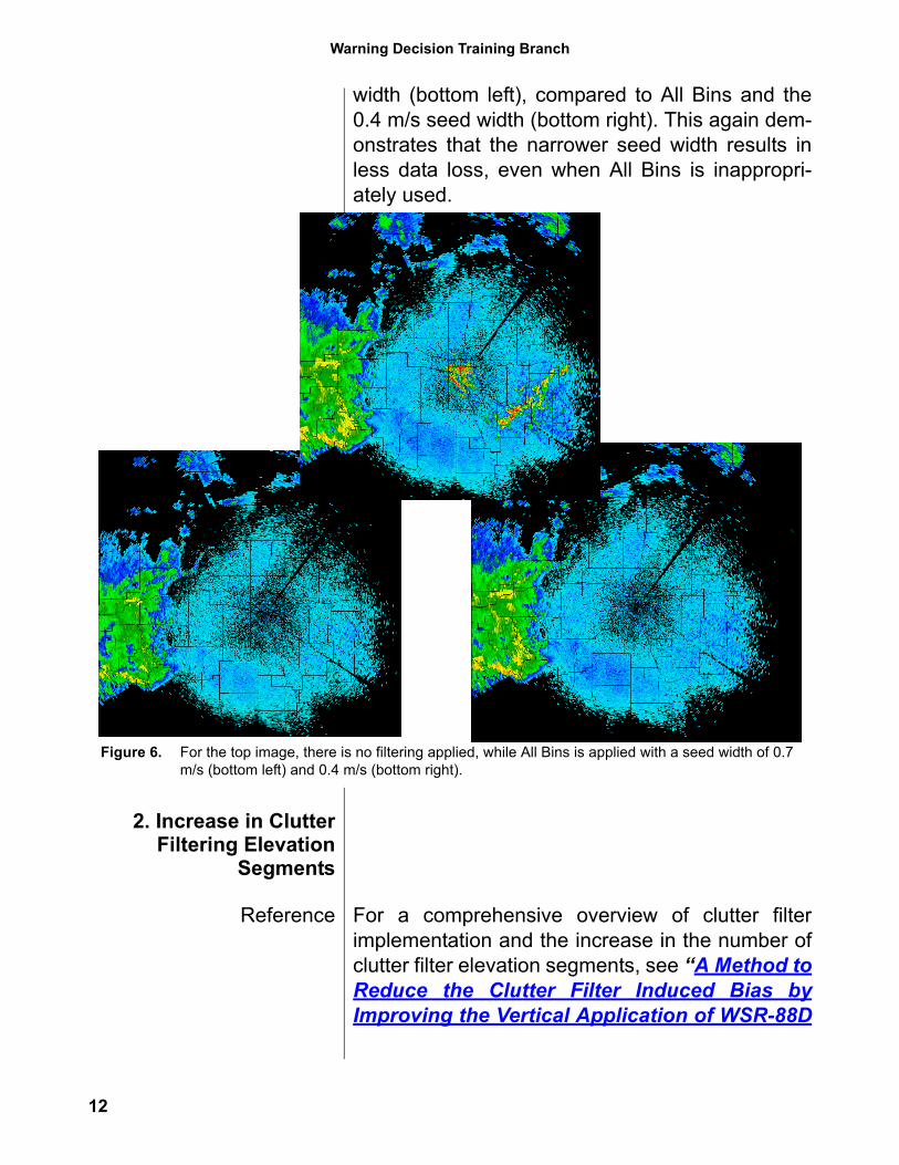
In Figure 6, a data case was processed with noclutter filtering (top), All Bins filtering and the pre-Build 9.0 seed width of 0.7 m/s (bottom left) and AllBins filtering and the Build 9.0 seed width of 0.4m/s (bottom right). Note that the areal coverage ofclear air return is slightly increased with the nar-rower Build 9.0 seed width (bottom right), com-pared to the pre-Build 9.0 seed width of 0.7 m/s(bottom left).
The area of precipitation is associated with lowvelocities and spectrum width. Note that there issome reduction in the areal coverage and intensityof precipitation with All Bins and the 0.7 m/s seed
Figure 5. Data loss along the zero isodop for the Build 9.0 GMAP seed width of 0.4 m/s. Note the area of data loss is smaller with 0.4 m/s.
11
Warning Decision Training Branch
width (bottom left), compared to All Bins and the0.4 m/s seed width (bottom right). This again dem-onstrates that the narrower seed width results inless data loss, even when All Bins is inappropri-ately used.
2. Increase in ClutterFiltering Elevation
Segments
Reference For a comprehensive overview of clutter filterimplementation and the increase in the number ofclutter filter elevation segments, see “A Method toReduce the Clutter Filter Induced Bias byImproving the Vertical Application of WSR-88D
Figure 6. For the top image, there is no filtering applied, while All Bins is applied with a seed width of 0.7 m/s (bottom left) and 0.4 m/s (bottom right).
12
RDA/RPG Build 9.0 Training
Bypass Maps”; J. Chrisman, Radar OperationsCenter; C. Ray, RS Information Systems.
This document is available for download from theBuild 9.0 Training web site and the URL will bepresented in the Summary section on page 53.
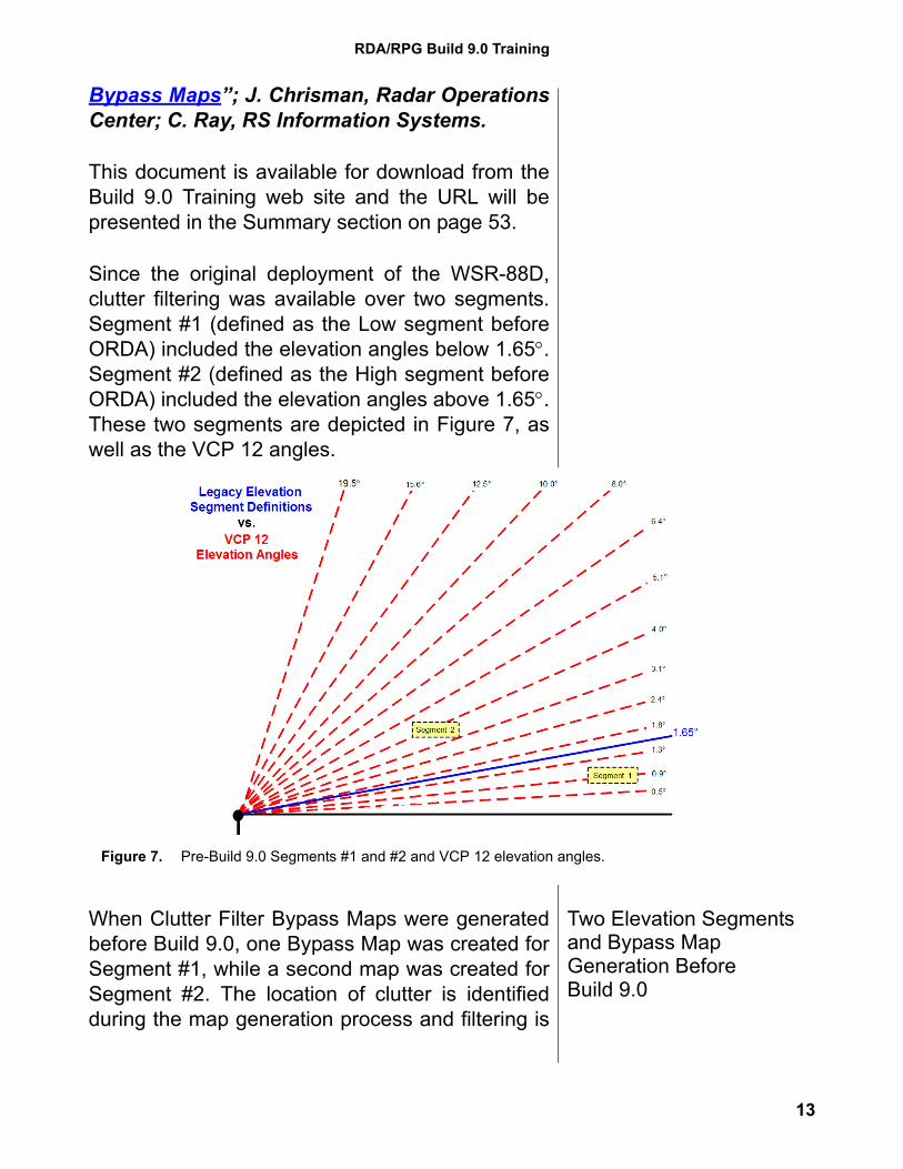
Since the original deployment of the WSR-88D,clutter filtering was available over two segments.Segment #1 (defined as the Low segment beforeORDA) included the elevation angles below 1.65°.Segment #2 (defined as the High segment beforeORDA) included the elevation angles above 1.65°.These two segments are depicted in Figure 7, aswell as the VCP 12 angles.
Two Elevation Segments and Bypass Map Generation Before Build 9.0
When Clutter Filter Bypass Maps were generatedbefore Build 9.0, one Bypass Map was created forSegment #1, while a second map was created forSegment #2. The location of clutter is identifiedduring the map generation process and filtering is
Figure 7. Pre-Build 9.0 Segments #1 and #2 and VCP 12 elevation angles.
13
Warning Decision Training Branch
performed on those identified bins when theBypass Map is in control.
Since the clutter pattern decreases with elevation,clutter at the lower angles within a segment domi-nates the Bypass Map for that segment. Filteringbased on this pattern is then applied to all the ele-vation angles within that segment. Using Figure 7,assume that clutter is encountered up to 2.4°, butno higher. The Segment #2 Bypass Map identifiesclutter targets encountered at 1.8° and 2.4°, andbased on this pattern, filtering is applied to everyelevation within Segment #2.
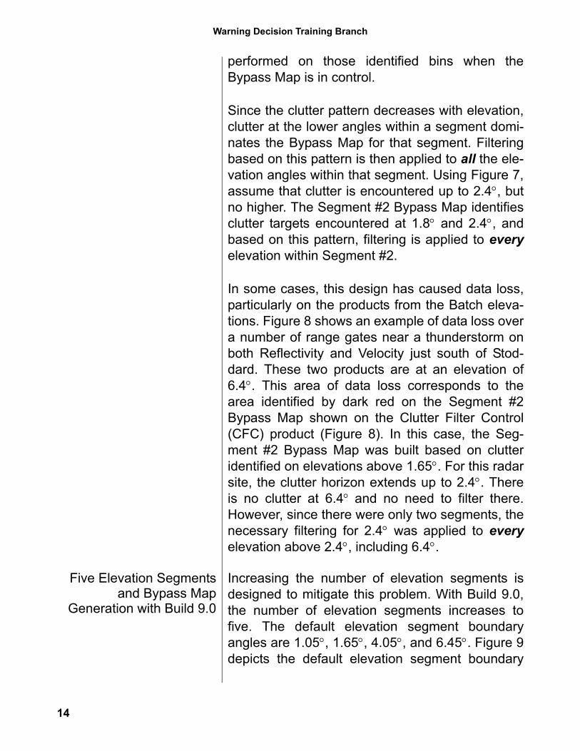
In some cases, this design has caused data loss,particularly on the products from the Batch eleva-tions. Figure 8 shows an example of data loss overa number of range gates near a thunderstorm onboth Reflectivity and Velocity just south of Stod-dard. These two products are at an elevation of6.4°. This area of data loss corresponds to thearea identified by dark red on the Segment #2Bypass Map shown on the Clutter Filter Control(CFC) product (Figure 8). In this case, the Seg-ment #2 Bypass Map was built based on clutteridentified on elevations above 1.65°. For this radarsite, the clutter horizon extends up to 2.4°. Thereis no clutter at 6.4° and no need to filter there.However, since there were only two segments, thenecessary filtering for 2.4° was applied to everyelevation above 2.4°, including 6.4°.
Five Elevation Segmentsand Bypass Map
Generation with Build 9.0
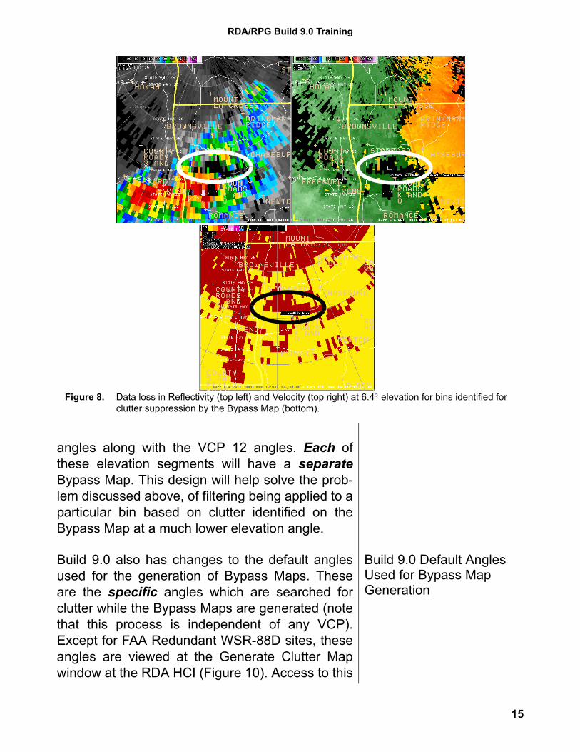
Increasing the number of elevation segments isdesigned to mitigate this problem. With Build 9.0,the number of elevation segments increases tofive. The default elevation segment boundaryangles are 1.05°, 1.65°, 4.05°, and 6.45°. Figure 9depicts the default elevation segment boundary
14
RDA/RPG Build 9.0 Training
angles along with the VCP 12 angles. Each ofthese elevation segments will have a separateBypass Map. This design will help solve the prob-lem discussed above, of filtering being applied to aparticular bin based on clutter identified on theBypass Map at a much lower elevation angle.
Build 9.0 Default Angles Used for Bypass Map Generation
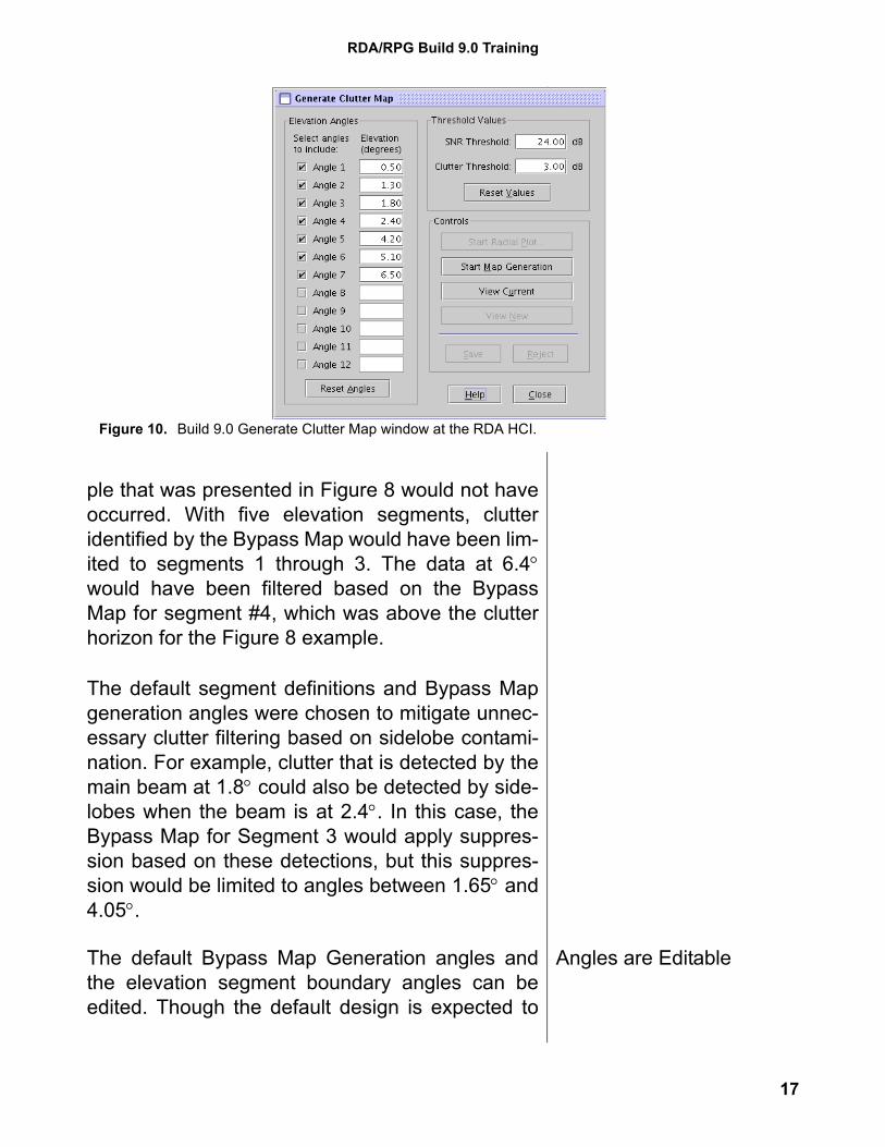
Build 9.0 also has changes to the default anglesused for the generation of Bypass Maps. Theseare the specific angles which are searched forclutter while the Bypass Maps are generated (notethat this process is independent of any VCP).Except for FAA Redundant WSR-88D sites, theseangles are viewed at the Generate Clutter Mapwindow at the RDA HCI (Figure 10). Access to this
Figure 8. Data loss in Reflectivity (top left) and Velocity (top right) at 6.4° elevation for bins identified for clutter suppression by the Bypass Map (bottom).
15
Warning Decision Training Branch
window requires that a meteorologist and a techni-cian work together to generate new Bypass Maps.
Note: The Build 9.0 default values for the SNRThreshold and the Clutter Threshold are 9.00 dBfor both. It is recommended that these values beedited to 24.0 dB for SNR Threshold and 3.00 dBfor Clutter Threshold, as shown in Figure 10.
The new default angles for Bypass Map genera-tion provide better vertical resolution and aredesigned to correspond to the five new elevationsegments. This configuration results in one or twoangles per segment which are searched for clutterwhen the Bypass Maps are generated.
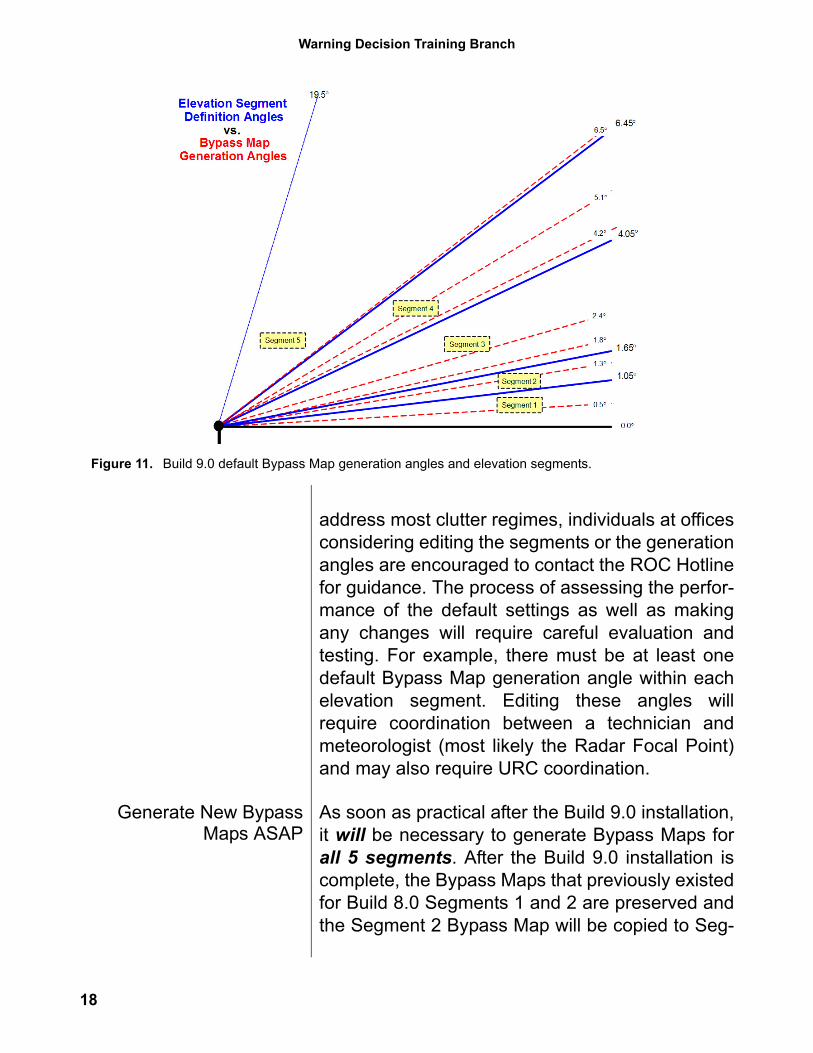
Figure 11 depicts the relationship between theBuild 9.0 default Bypass Map generation anglesand the angles which define the five elevation seg-ments. With this configuration, the data loss exam-
Figure 9. Build 9.0 default Elevation Segment Angles and VCP 12 angles.
16
RDA/RPG Build 9.0 Training
ple that was presented in Figure 8 would not haveoccurred. With five elevation segments, clutteridentified by the Bypass Map would have been lim-ited to segments 1 through 3. The data at 6.4°would have been filtered based on the BypassMap for segment #4, which was above the clutterhorizon for the Figure 8 example.
The default segment definitions and Bypass Mapgeneration angles were chosen to mitigate unnec-essary clutter filtering based on sidelobe contami-nation. For example, clutter that is detected by themain beam at 1.8° could also be detected by side-lobes when the beam is at 2.4°. In this case, theBypass Map for Segment 3 would apply suppres-sion based on these detections, but this suppres-sion would be limited to angles between 1.65° and4.05°.
Angles are EditableThe default Bypass Map Generation angles andthe elevation segment boundary angles can beedited. Though the default design is expected to
Figure 10. Build 9.0 Generate Clutter Map window at the RDA HCI.
17
Warning Decision Training Branch
address most clutter regimes, individuals at officesconsidering editing the segments or the generationangles are encouraged to contact the ROC Hotlinefor guidance. The process of assessing the perfor-mance of the default settings as well as makingany changes will require careful evaluation andtesting. For example, there must be at least onedefault Bypass Map generation angle within eachelevation segment. Editing these angles willrequire coordination between a technician andmeteorologist (most likely the Radar Focal Point)and may also require URC coordination.
Generate New BypassMaps ASAP
As soon as practical after the Build 9.0 installation,it will be necessary to generate Bypass Maps forall 5 segments. After the Build 9.0 installation iscomplete, the Bypass Maps that previously existedfor Build 8.0 Segments 1 and 2 are preserved andthe Segment 2 Bypass Map will be copied to Seg-
Figure 11. Build 9.0 default Bypass Map generation angles and elevation segments.
18
RDA/RPG Build 9.0 Training
ment 3. There will be no suppression defined forSegments 4 and 5.
Even for flatland sites with little terrain, sidelobescan encounter man made clutter targets. Thoughconfined to a very close range to the radar, clutterdetected by sidelobes has been observed up to6.5° at some flatland sites. That is why it is soimportant to generate new Bypass Maps for all fivesegments as soon as possible after the Build 9.0installation. Meteorologists are encouraged tocoordinate with technicians to achieve this goal(instructions for technicians are available at NWSEHB 6-515 Revision 1, dated 15 May 2007, para-graph 6.6.3.4.8).
NWS Redundant site will need to build BypassMaps for one side and copy the maps to the otherside. Details are available as part of the Build 9.0Release Notes.
Note: The Build 9.0 default values for the SNRThreshold and the Clutter Threshold are 9.00 dBfor both. It is recommended that these values beedited to 24.0 dB for SNR Threshold and 3.00 dBfor Clutter Threshold, as shown in Figure 10. See“Bypass Map Generation Guidance” available fordownload from the Build 9.0 Training web site(URL in the Summary section on page 53).
3. SZ-2 Algorithm
ReferencesFor a comprehensive overview of the problem ofrange folding, the legacy Range Unfolding Algo-rithm, and the new SZ-2 Algorithm, see “New Sci-ence for the WSR-88D: Implementing a MajorMode on the SIGMET RVP8” D. Saxion, R. Rho-ton, R. Ice, G. McGehee, RS Information Sys-tems; D. Warde, SI International; O. Boydstun,
19
Warning Decision Training Branch
D. Zittel, Radar Operations Center; S. Torres,National Severe Storms Laboratory; G. Mey-maris, National Center for AtmosphericResearch.
Also see “Concept of Operations for the SZ-2Range-Folding Mitigation Technique” D. Zittel,Radar Operations Center.
These documents are available for download fromthe Build 9.0 Training web site and the URL will bepresented in the Summary section on page 53.
Some History The problem of range folding with the high PRFsneeded for velocity and spectrum width estimateshas been a fundamental limitation of Doppler datacollection. The Range Unfolding Algorithm hasbeen in use since the original deployment of theWSR-88D. When echoes are overlaid, the RangeUnfolding Algorithm can recover one of the veloc-ity estimates, provided the associated returnedpower is significantly greater than the otherecho(es). The next step in mitigating range foldingwas the fielding of VCP 121, which uses the Multi-ple PRF Dealiasing Algorithm (MPDA). On thelower elevations, multiple Doppler rotations (2 or3) with different PRFs are each range unfoldedusing the legacy Range Unfolding Algorithm. Thisimproves the availability of a velocity or spectrumwidth estimate for any particular range bin. VCP121 results in a significant improvement in recov-ering velocity data, as compared to legacy RangeUnfolding with a single Doppler rotation.
The SZ-2 Algorithm is the next step in this evolu-tion. It is executed at the signal processor at theRDA. SZ-2 can significantly reduce range foldingcompared to the legacy Range Unfolding Algo-
20
RDA/RPG Build 9.0 Training
rithm or MPDA. As with the legacy Range Unfold-ing Algorithm, base data that are range unfoldedby SZ-2 are then passed to the legacy VelocityDealiasing Algorithm for velocity unfolding.
SZ-2 OverviewThe SZ-2 Algorithm offers an alternative methodfor mitigating range folding on velocity and spec-trum width products. In this document, the term“velocity data” is meant to include both velocityand spectrum width. SZ-2 is named for theresearch scientists that developed the algorithm,Mangalore Sachidananda and Dusan Zrnic. SZ-2is applied only to the Split Cut elevations and isavailable by selecting specific VCPs: 211, 221,and 212.
How Does SZ-2 Differ from Legacy Range Unfolding?
Multiple trip echoes are common with the velocitydata because high PRFs are necessary for goodquality velocity estimates. Thus some type of“unfolding” technique is necessary. The legacyRange Unfolding Algorithm is used for the Batchelevations in all of the VCPs. The SZ-2 VCPs useSZ-2 only for the Split Cut elevations. The non-SZ-2 VCPs use legacy Range Unfolding for theSplit Cut elevations.
The legacy Range Unfolding Algorithm can, atbest, recover one velocity estimate from thehigher power echo, assigning Range Folded (RF)to the other(s). In most cases of echo overlay, theSZ-2 algorithm has the ability to recover velocityfor two overlaid echoes.
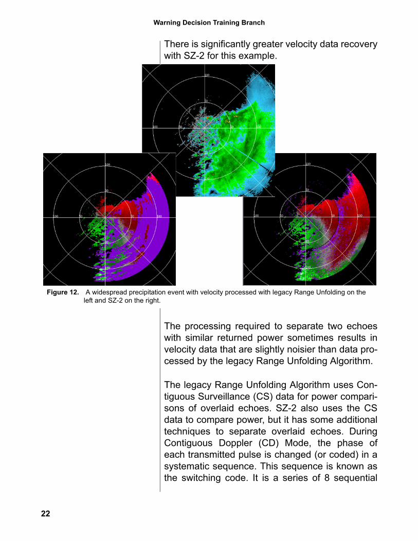
In some cases, the difference between the legacyRange Unfolding Algorithm and SZ-2 can be dra-matic. In Figure 12, there is widespread precipita-tion southeast of the radar. The velocity data hasbeen processed by the legacy Range UnfoldingAlgorithm on the left and by SZ-2 on the right.
21
Warning Decision Training Branch
There is significantly greater velocity data recoverywith SZ-2 for this example.
The processing required to separate two echoeswith similar returned power sometimes results invelocity data that are slightly noisier than data pro-cessed by the legacy Range Unfolding Algorithm.
The legacy Range Unfolding Algorithm uses Con-tiguous Surveillance (CS) data for power compari-sons of overlaid echoes. SZ-2 also uses the CSdata to compare power, but it has some additionaltechniques to separate overlaid echoes. DuringContiguous Doppler (CD) Mode, the phase ofeach transmitted pulse is changed (or coded) in asystematic sequence. This sequence is known asthe switching code. It is a series of 8 sequential
Figure 12. A widespread precipitation event with velocity processed with legacy Range Unfolding on the left and SZ-2 on the right.
22
RDA/RPG Build 9.0 Training
transmitted phase values with the series repeated8 times, resulting in a total of 64 pulses. An impor-tant requirement for SZ-2 is that there must beexactly 64 Doppler pulses per radial.
Implementing SZ-2The requirement for 64 pulses per radial meansthat operators are not allowed to change the Dop-pler PRF for Split Cut elevations where SZ-2 isapplied. Operational impacts when using the SZ-2VCPs will be presented in more detail in “Using theSZ-2 VCPs”, (RPG Build 9.0 Impacts) beginningon page 33.
SZ-2 and the Radio Frequency (RF) Generator
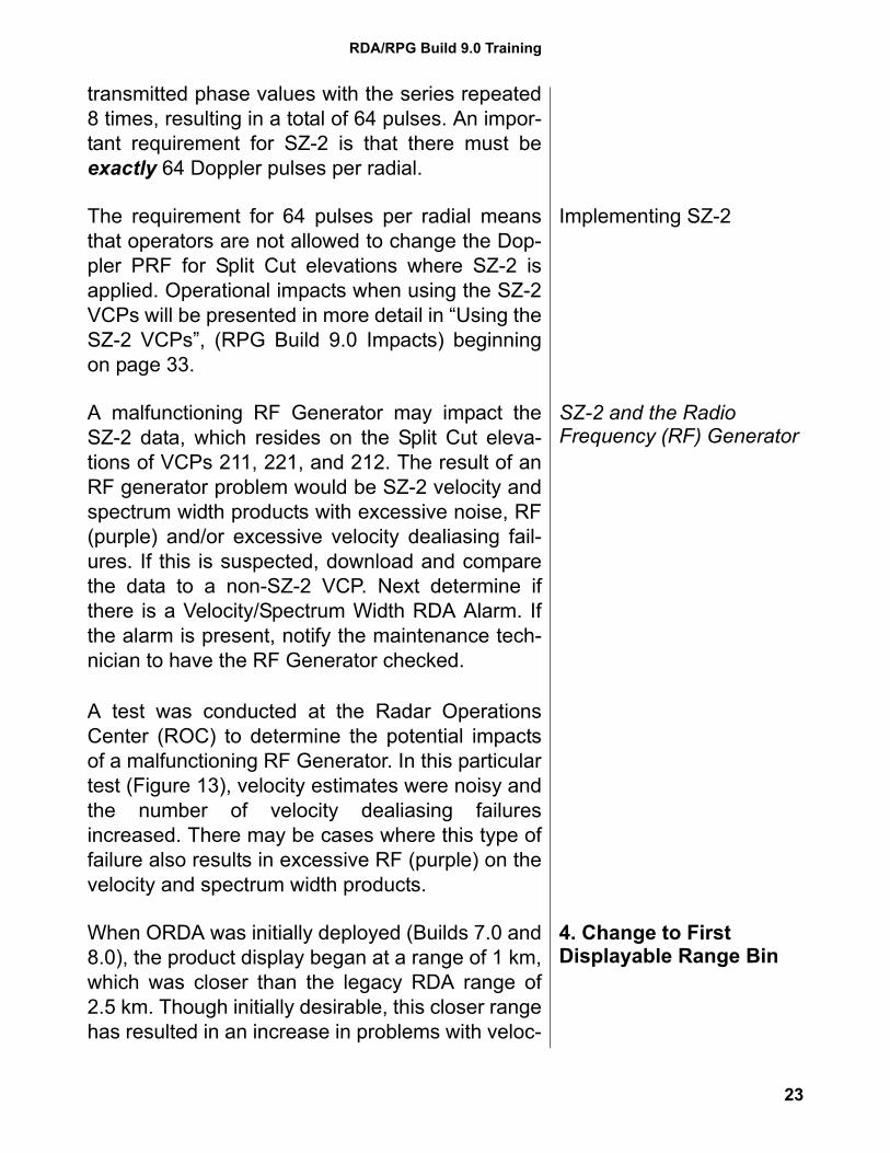
A malfunctioning RF Generator may impact theSZ-2 data, which resides on the Split Cut eleva-tions of VCPs 211, 221, and 212. The result of anRF generator problem would be SZ-2 velocity andspectrum width products with excessive noise, RF(purple) and/or excessive velocity dealiasing fail-ures. If this is suspected, download and comparethe data to a non-SZ-2 VCP. Next determine ifthere is a Velocity/Spectrum Width RDA Alarm. Ifthe alarm is present, notify the maintenance tech-nician to have the RF Generator checked.
A test was conducted at the Radar OperationsCenter (ROC) to determine the potential impactsof a malfunctioning RF Generator. In this particulartest (Figure 13), velocity estimates were noisy andthe number of velocity dealiasing failuresincreased. There may be cases where this type offailure also results in excessive RF (purple) on thevelocity and spectrum width products.
4. Change to First Displayable Range Bin
When ORDA was initially deployed (Builds 7.0 and8.0), the product display began at a range of 1 km,which was closer than the legacy RDA range of2.5 km. Though initially desirable, this closer rangehas resulted in an increase in problems with veloc-
23
Warning Decision Training Branch
ity and spectrum width estimates causing RDAalarms. With Build 9.0, the product display beginsat a range of 2 km. Thus the “hole” at the center ofthe products will be slightly bigger. This change tothe “blind spot” at the center of products is a goodreminder of the need to use an adjacent radar toovercome the blind spot and the cone of silence.
RPG Build 9.0Operational
Impacts
The remainder of this document covers the elevenBuild 9.0 impacts at the RPG. Some of the impactsat the RPG are unrelated to RDA changes (otherthan the two systems have to stay connected!).The best example of RPG changes unrelated tothe RDA is the RPG Refresh, which is a redesignof the RPG that includes new hardware and soft-ware. On the other hand, some RDA changes,such as the SZ-2 Algorithm, also have a bigimpact at the RPG, since implementing SZ-2requires downloading specific VCPs.
1. RPG Refresh RPG Refresh is a replacement and redesign ofboth hardware and software. The long term goal is
Figure 13. Results from a malfunctioning RF Generator test. Velocity estimates are noisy and velocity dealiasing failures are excessive.
24
RDA/RPG Build 9.0 Training
to have multiple processors running the algorithmsand generating products, while the RPG softwarebalances the workload among the processors.RPG Refresh is the first step in this redesign pro-cess. It addresses obsolescence of componentsas well as needed infrastructure redesign.
The MSCF/RPG operating system changes fromSolaris 8 to Red Hat Enterprise Linux 4. There aretwo processors running with Build 9.0 and tasksare distributed between these two processors. TheRPG Refresh infrastructure allows for up to eightprocessors. The MSCF hardware is also upgradedfrom the SUN Ultra 5 to a PC. The RPG compo-nents are Commercial Off the Shelf (COTS) andare easy to replace.
2. RPG HCI Window Changes
The conversion to a Linux operating systemslightly changes the look of all the RPG HCI win-dows. One functional change for the windows isthe minimize and close buttons on the upper rightof each window.
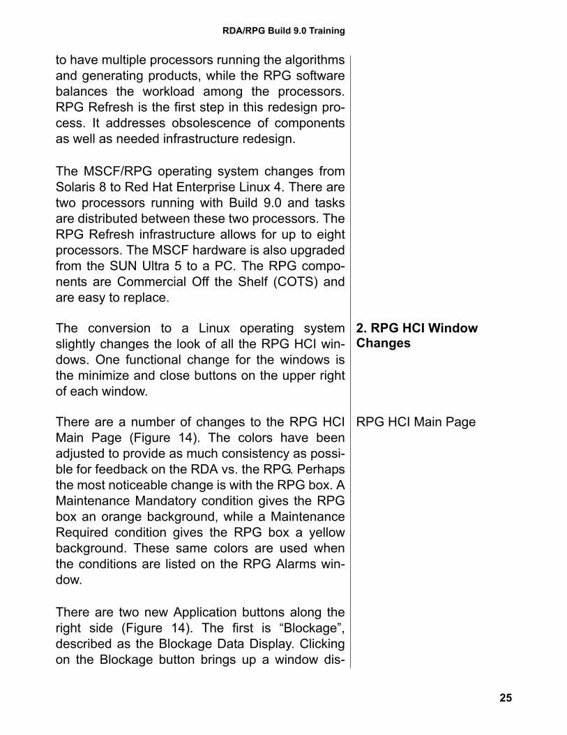
RPG HCI Main PageThere are a number of changes to the RPG HCIMain Page (Figure 14). The colors have beenadjusted to provide as much consistency as possi-ble for feedback on the RDA vs. the RPG. Perhapsthe most noticeable change is with the RPG box. AMaintenance Mandatory condition gives the RPGbox an orange background, while a MaintenanceRequired condition gives the RPG box a yellowbackground. These same colors are used whenthe conditions are listed on the RPG Alarms win-dow.
There are two new Application buttons along theright side (Figure 14). The first is “Blockage”,described as the Blockage Data Display. Clickingon the Blockage button brings up a window dis-
25
Warning Decision Training Branch
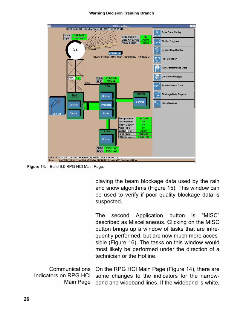
playing the beam blockage data used by the rainand snow algorithms (Figure 15). This window canbe used to verify if poor quality blockage data issuspected.
The second Application button is “MISC”described as Miscellaneous. Clicking on the MISCbutton brings up a window of tasks that are infre-quently performed, but are now much more acces-sible (Figure 16). The tasks on this window wouldmost likely be performed under the direction of atechnician or the Hotline.
CommunicationsIndicators on RPG HCI
Main Page
On the RPG HCI Main Page (Figure 14), there aresome changes to the indicators for the narrow-band and wideband lines. If the wideband is white,
Figure 14. Build 9.0 RPG HCI Main Page.
26
RDA/RPG Build 9.0 Training
it is connected, but the data moments (specificallyR) are not enabled. If the wideband is yellow, it hasbeen disconnected by an operator or a connect ispending. If the wideband is green without the R, V,and W markers, it is connected, but the base dataare not flowing. If the wideband is green and the R,V, and W markers are moving, it is connected andthe base data are flowing.
Figure 15. Build 9.0 Blockage Data Display window.
Figure 16. Build 9.0 Miscellaneous window.
27
Warning Decision Training Branch
If any single narrowband line is connected, thenarrowband line is green. There is no longer ananimation when the data are flowing. If any singlenarrowband line has failed, the line is red. If all ofthe narrowband lines are disconnected (anunlikely event), the line disappears.
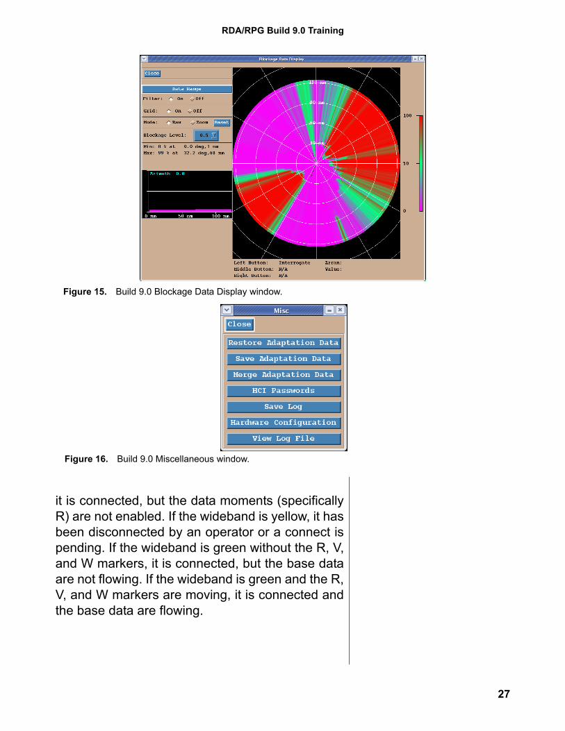
RPG Status Window The choices regarding the filtering of all the statusinformation on the RPG Status window have beencombined. By clicking on the Message Filter but-ton on the RPG Status window, a new windowopens where filtering options for RDA Alarms,RPG Alarms and RPG Status messages can beselected (Figure 17).
RPG Control Window Two important tasks are now directly available atthe RPG Control window once it is unlocked (Fig-ure 18):
1. Reset Snow Accumulation
Figure 17. Build 9.0 RPG Status window and Message Filter window.
28
RDA/RPG Build 9.0 Training
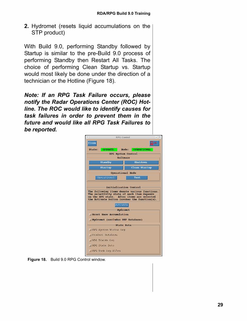
2. Hydromet (resets liquid accumulations on theSTP product)
With Build 9.0, performing Standby followed byStartup is similar to the pre-Build 9.0 process ofperforming Standby then Restart All Tasks. Thechoice of performing Clean Startup vs. Startupwould most likely be done under the direction of atechnician or the Hotline (Figure 18).
Note: If an RPG Task Failure occurs, pleasenotify the Radar Operations Center (ROC) Hot-line. The ROC would like to identify causes fortask failures in order to prevent them in thefuture and would like all RPG Task Failures tobe reported.
Figure 18. Build 9.0 RPG Control window.
29
Warning Decision Training Branch
3. RPG Impacts ofIncrease in ClutterFiltering ElevationSegments at RDA
Though the increase in clutter filter elevation seg-ments resides at the RDA, there are implementa-tion impacts at the RPG. The Clutter Regionseditor window reflects the increase from two to fiveelevation segments, which are included in a singleClutter Regions file. The biggest impact is theexisting limit of 15 regions per Clutter Regions file.Prior to Build 9.0, this has meant a total of 15regions over two segments and thus the impactwas minimal.
What is a Clutter RegionsFile?
A Clutter Regions file allows for customizing ofclutter filtering. Suppression controlled by theBypass Map is appropriate for most conditionsexcept Anomalous Propagation (AP) clutter. Theappropriate combination of Bypass Map and AllBins suppression is the most effective way to man-age areas of AP clutter. When editing any ClutterRegions file, it is still recommended that line 1have the Bypass Map in control everywhere (Fig-ure 20), with additional areas drawn to address APclutter as needed. Line 1 is one of the 15 regionsallowed per file.
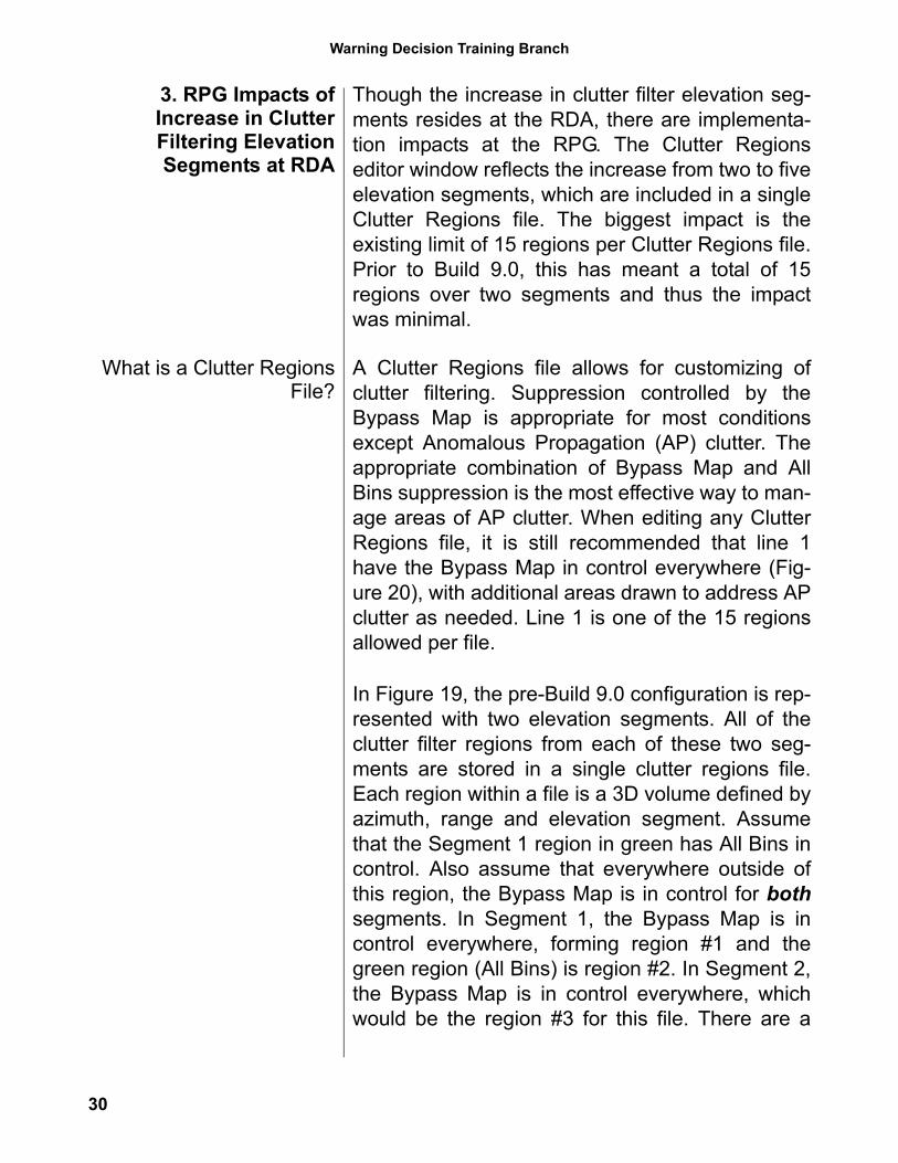
In Figure 19, the pre-Build 9.0 configuration is rep-resented with two elevation segments. All of theclutter filter regions from each of these two seg-ments are stored in a single clutter regions file.Each region within a file is a 3D volume defined byazimuth, range and elevation segment. Assumethat the Segment 1 region in green has All Bins incontrol. Also assume that everywhere outside ofthis region, the Bypass Map is in control for bothsegments. In Segment 1, the Bypass Map is incontrol everywhere, forming region #1 and thegreen region (All Bins) is region #2. In Segment 2,the Bypass Map is in control everywhere, whichwould be the region #3 for this file. There are a
30
RDA/RPG Build 9.0 Training
total of 3 regions for the associated ClutterRegions file.
All Segments within One File
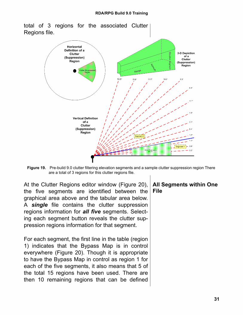
At the Clutter Regions editor window (Figure 20),the five segments are identified between thegraphical area above and the tabular area below.A single file contains the clutter suppressionregions information for all five segments. Select-ing each segment button reveals the clutter sup-pression regions information for that segment.
For each segment, the first line in the table (region1) indicates that the Bypass Map is in controleverywhere (Figure 20). Though it is appropriateto have the Bypass Map in control as region 1 foreach of the five segments, it also means that 5 ofthe total 15 regions have been used. There arethen 10 remaining regions that can be defined
Figure 19. Pre-build 9.0 clutter filtering elevation segments and a sample clutter suppression region There are a total of 3 regions for this clutter regions file.
31
Warning Decision Training Branch
among the five segments to address AP clutter.For locations with complex terrain, this limit mayrequire some careful planning.
Note: After Build 9.0 is installed, new BypassMaps need to be generated for all 5 segments. Foradditional information, see “Generate New BypassMaps ASAP” on page 18. New Bypass Maps for all5 segments will create a new Default ClutterRegions file with the Bypass Map in control every-where. For offices with predictable areas of APclutter due to terrain, additional files will need to bedefined to apply All Bins suppression to theseareas.
Clutter Region FilesWindow
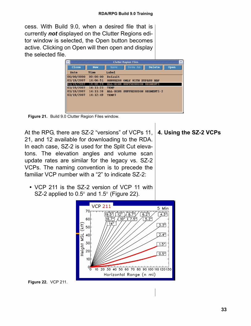
The Clutter Region Files window (Figure 21) has anew button labeled Open. Prior to Build 9.0, it wasnecessary to double click on a file in order to openit. There were occasional problems with this pro-
Figure 20. Build 9.0 Clutter Regions editor window at the RPG HCI.
32
RDA/RPG Build 9.0 Training
cess. With Build 9.0, when a desired file that iscurrently not displayed on the Clutter Regions edi-tor window is selected, the Open button becomesactive. Clicking on Open will then open and displaythe selected file.
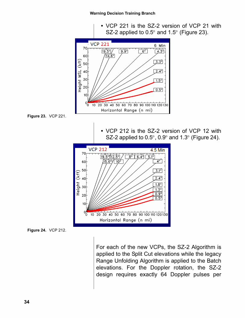
4. Using the SZ-2 VCPsAt the RPG, there are SZ-2 “versions” of VCPs 11,21, and 12 available for downloading to the RDA.In each case, SZ-2 is used for the Split Cut eleva-tons. The elevation angles and volume scanupdate rates are similar for the legacy vs. SZ-2VCPs. The naming convention is to precede thefamiliar VCP number with a “2” to indicate SZ-2:
• VCP 211 is the SZ-2 version of VCP 11 withSZ-2 applied to 0.5° and 1.5° (Figure 22).
Figure 21. Build 9.0 Clutter Region Files window.
Figure 22. VCP 211.
33
Warning Decision Training Branch
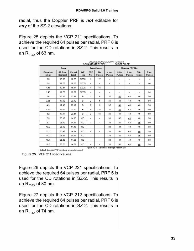
• VCP 221 is the SZ-2 version of VCP 21 withSZ-2 applied to 0.5° and 1.5° (Figure 23).
• VCP 212 is the SZ-2 version of VCP 12 withSZ-2 applied to 0.5°, 0.9° and 1.3° (Figure 24).
For each of the new VCPs, the SZ-2 Algorithm isapplied to the Split Cut elevations while the legacyRange Unfolding Algorithm is applied to the Batchelevations. For the Doppler rotation, the SZ-2design requires exactly 64 Doppler pulses per
Figure 23. VCP 221.
Figure 24. VCP 212.
34
RDA/RPG Build 9.0 Training
radial, thus the Doppler PRF is not editable forany of the SZ-2 elevations.
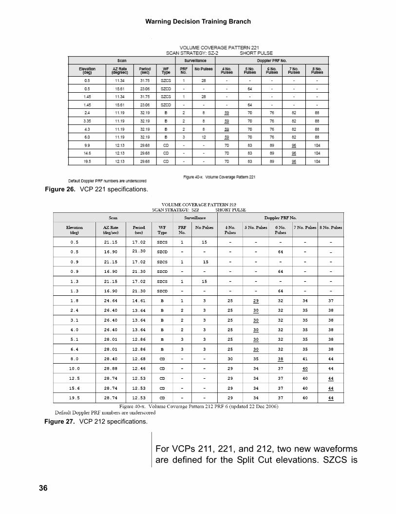
Figure 25 depicts the VCP 211 specifications. Toachieve the required 64 pulses per radial, PRF 8 isused for the CD rotations in SZ-2. This results inan Rmax of 63 nm.
Figure 26 depicts the VCP 221 specifications. Toachieve the required 64 pulses per radial, PRF 5 isused for the CD rotations in SZ-2. This results inan Rmax of 80 nm.
Figure 27 depicts the VCP 212 specifications. Toachieve the required 64 pulses per radial, PRF 6 isused for the CD rotations in SZ-2. This results inan Rmax of 74 nm.
Figure 25. VCP 211 specifications.
35
Warning Decision Training Branch
For VCPs 211, 221, and 212, two new waveformsare defined for the Split Cut elevations. SZCS is
Figure 26. VCP 221 specifications.
Figure 27. VCP 212 specifications.
36
RDA/RPG Build 9.0 Training
similar to CS, using a low PRF for range andpower. SZCD uses a high PRF just as the CDwaveform does, with the Doppler PRF held con-stant at 64 pulses per radial. VCPs 211 and 221have the same volume scan completion times asVCPs 11 and 21, five and six minutes, respec-tively. VCP 212 takes about 20 seconds longerthan VCP 12, with a completion time of about 4.5minutes.
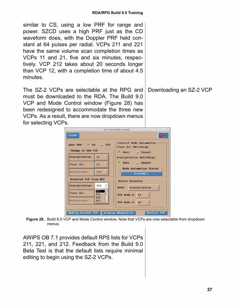
Downloading an SZ-2 VCPThe SZ-2 VCPs are selectable at the RPG andmust be downloaded to the RDA. The Build 9.0VCP and Mode Control window (Figure 28) hasbeen redesigned to accommodate the three newVCPs. As a result, there are now dropdown menusfor selecting VCPs.
AWIPS OB 7.1 provides default RPS lists for VCPs211, 221, and 212. Feedback from the Build 9.0Beta Test is that the default lists require minimalediting to begin using the SZ-2 VCPs.
Figure 28. Build 9.0 VCP and Mode Control window. Note that VCPs are now selectable from dropdown menus.
37
Warning Decision Training Branch
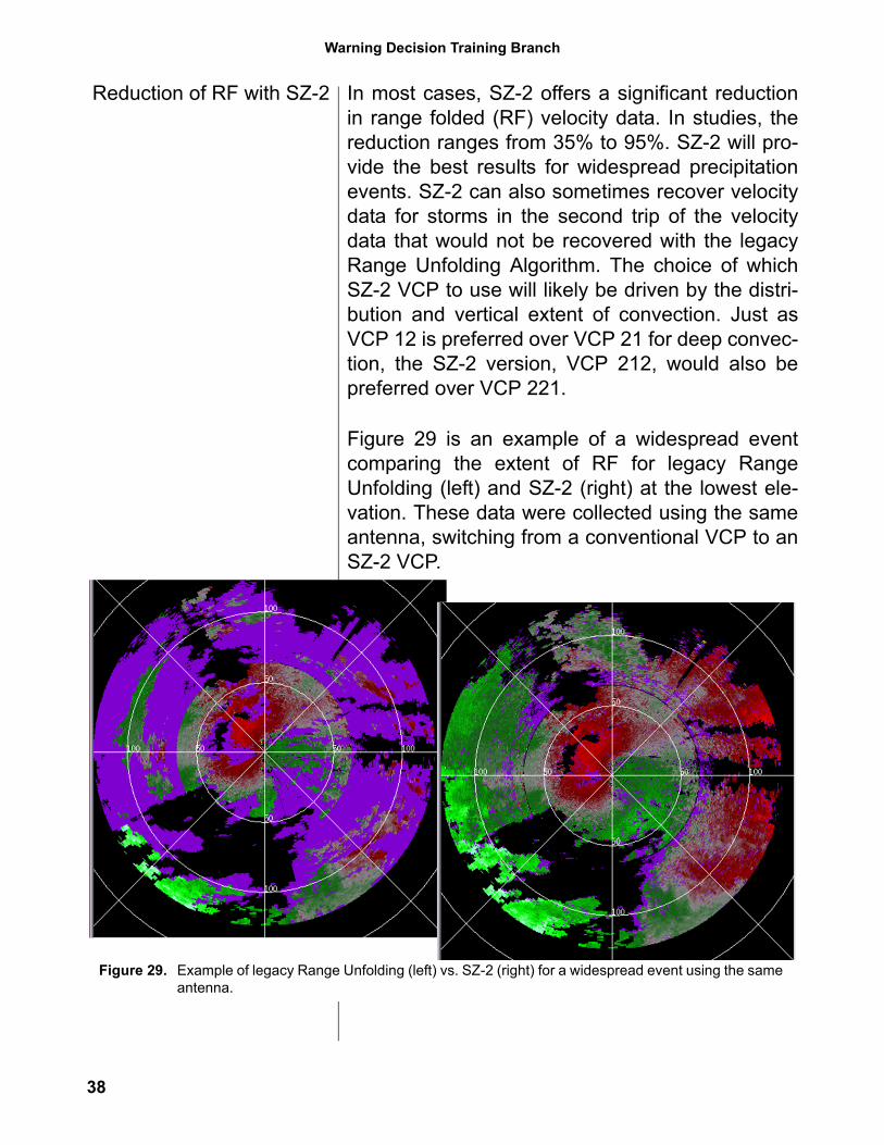
Reduction of RF with SZ-2 In most cases, SZ-2 offers a significant reductionin range folded (RF) velocity data. In studies, thereduction ranges from 35% to 95%. SZ-2 will pro-vide the best results for widespread precipitationevents. SZ-2 can also sometimes recover velocitydata for storms in the second trip of the velocitydata that would not be recovered with the legacyRange Unfolding Algorithm. The choice of whichSZ-2 VCP to use will likely be driven by the distri-bution and vertical extent of convection. Just asVCP 12 is preferred over VCP 21 for deep convec-tion, the SZ-2 version, VCP 212, would also bepreferred over VCP 221.
Figure 29 is an example of a widespread eventcomparing the extent of RF for legacy RangeUnfolding (left) and SZ-2 (right) at the lowest ele-vation. These data were collected using the sameantenna, switching from a conventional VCP to anSZ-2 VCP.
Figure 29. Example of legacy Range Unfolding (left) vs. SZ-2 (right) for a widespread event using the same antenna.
38
RDA/RPG Build 9.0 Training
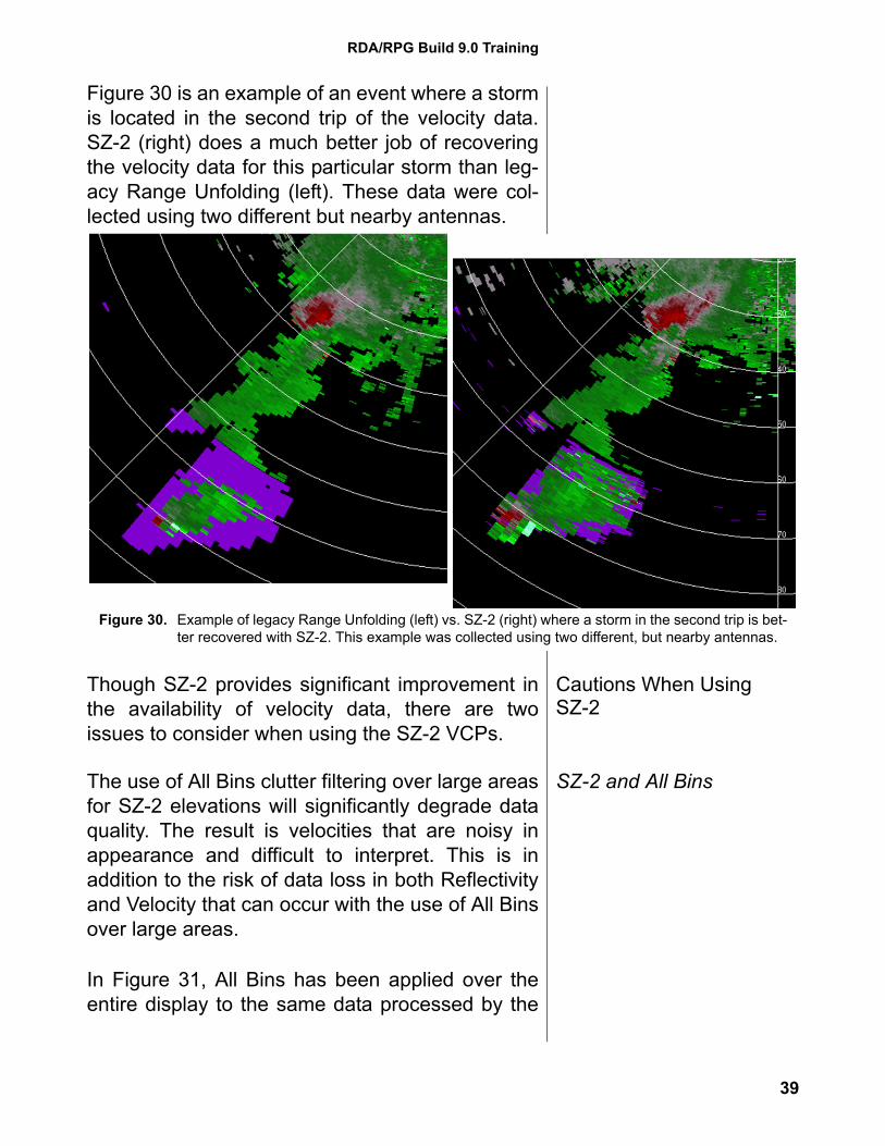
Figure 30 is an example of an event where a stormis located in the second trip of the velocity data.SZ-2 (right) does a much better job of recoveringthe velocity data for this particular storm than leg-acy Range Unfolding (left). These data were col-lected using two different but nearby antennas.
Cautions When Using SZ-2
Though SZ-2 provides significant improvement inthe availability of velocity data, there are twoissues to consider when using the SZ-2 VCPs.
SZ-2 and All BinsThe use of All Bins clutter filtering over large areasfor SZ-2 elevations will significantly degrade dataquality. The result is velocities that are noisy inappearance and difficult to interpret. This is inaddition to the risk of data loss in both Reflectivityand Velocity that can occur with the use of All Binsover large areas.
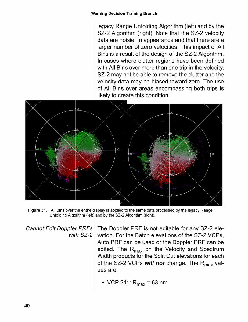
In Figure 31, All Bins has been applied over theentire display to the same data processed by the
Figure 30. Example of legacy Range Unfolding (left) vs. SZ-2 (right) where a storm in the second trip is bet-ter recovered with SZ-2. This example was collected using two different, but nearby antennas.
39
Warning Decision Training Branch
legacy Range Unfolding Algorithm (left) and by theSZ-2 Algorithm (right). Note that the SZ-2 velocitydata are noisier in appearance and that there are alarger number of zero velocities. This impact of AllBins is a result of the design of the SZ-2 Algorithm.In cases where clutter regions have been definedwith All Bins over more than one trip in the velocity,SZ-2 may not be able to remove the clutter and thevelocity data may be biased toward zero. The useof All Bins over areas encompassing both trips islikely to create this condition.
Cannot Edit Doppler PRFswith SZ-2
The Doppler PRF is not editable for any SZ-2 ele-vation. For the Batch elevations of the SZ-2 VCPs,Auto PRF can be used or the Doppler PRF can beedited. The Rmax on the Velocity and SpectrumWidth products for the Split Cut elevations for eachof the SZ-2 VCPs will not change. The Rmax val-ues are:
• VCP 211: Rmax = 63 nm
Figure 31. All Bins over the entire display is applied to the same data processed by the legacy Range Unfolding Algorithm (left) and by the SZ-2 Algorithm (right).
40
RDA/RPG Build 9.0 Training
• VCP 221: Rmax = 80 nm
• VCP 212: Rmax = 74 nm
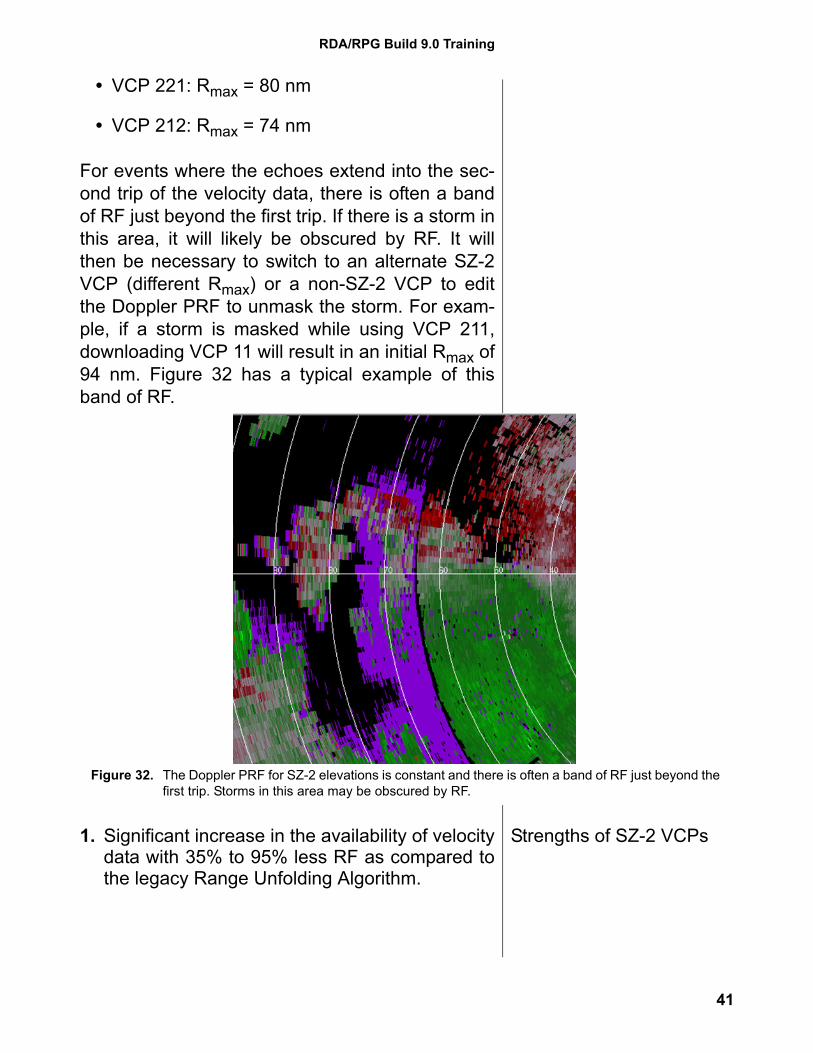
For events where the echoes extend into the sec-ond trip of the velocity data, there is often a bandof RF just beyond the first trip. If there is a storm inthis area, it will likely be obscured by RF. It willthen be necessary to switch to an alternate SZ-2VCP (different Rmax) or a non-SZ-2 VCP to editthe Doppler PRF to unmask the storm. For exam-ple, if a storm is masked while using VCP 211,downloading VCP 11 will result in an initial Rmax of94 nm. Figure 32 has a typical example of thisband of RF.
Strengths of SZ-2 VCPs1. Significant increase in the availability of velocitydata with 35% to 95% less RF as compared tothe legacy Range Unfolding Algorithm.
Figure 32. The Doppler PRF for SZ-2 elevations is constant and there is often a band of RF just beyond the first trip. Storms in this area may be obscured by RF.
41
Warning Decision Training Branch
2. Best results from events with radar returns overwidespread areas, which maximizes echo over-lay.
Limitations of SZ-2 VCPs 1. Use of All Bins over large areas will degradethe quality of the velocity estimates. Use of theSZ-2 VCPs is discouraged when AP clutter ispresent, requiring All Bins to address the APclutter.
2. For the SZ-2 VCPs, the Doppler PRF for theSplit Cut (SZ-2) elevations is constant and noteditable. It is typical for a small band of RF datato exist just beyond the first trip with SZ-2. If asignificant storm is in this area of RF, a differentVCP will be needed. A different SZ-2 VCP (witha different Rmax) may be sufficient, or a legacyVCP with the capability to edit the Doppler PRFmay be needed.
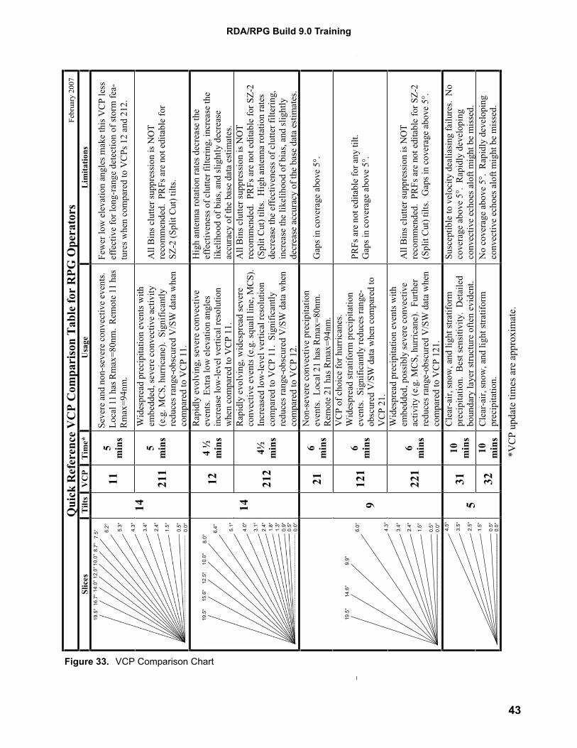
VCP Comparison Chartand VCP Naming Strategy
The new VCPs introduced with Build 9.0 increasesthe challenge of determining the best VCP for agiven situation. The VCP Comparison Chart (Fig-ure 33) is a summary of the uses and limitationsfor the available VCPs.
VCPs 11, 12, 21, 31, and 32 are most familiar tousers and all use two digit names. Among theVCPs with three digits are 121, 211, 221, and 212.VCP 121 is the only MPDA VCP, and the preced-ing 1 signals that this is an MPDA VCP. The 1 isfollowed by 21, which tells you that this VCP usesthe same angles as VCP 21.
The SZ-2 VCPs are all preceded by a 2. Theremaining digits tell you which angles are used.For example, VCP 212 uses the same angles asVCP 12. The difference is that SZ-2 is usedinstead of legacy Range Unfolding on the Split Cutelevations.
42
RDA/RPG Build 9.0 Training
Qui
ck R
efer
ence
VC
P C
ompa
riso
n Ta
ble
for
RPG
Ope
rato
rs
Slic
es
Tilt
s V
CP
Tim
e*
Usa
ge
Lim
itatio
ns
115
min
s Se
vere
and
non
-sev
ere
conv
ectiv
e ev
ents
. Lo
cal 1
1 ha
s Rm
ax=8
0nm
. R
emot
e 11
ha
s Rm
ax=9
4nm
.
Elev
atio
n sp
acin
g be
low
5° i
s not
wel
l sui
ted
for
long
rang
e de
tect
ion
of c
ircul
atio
ns.
14
211
5m
ins
Wid
espr
ead
prec
ipita
tion
even
ts w
ith
embe
dded
, sev
ere
conv
ectiv
e ac
tivity
(e
.g. M
CS,
hur
rican
e).
Sign
ifica
ntly
re
duce
s ran
ge-o
bscu
red
V/S
W d
ata
whe
n co
mpa
red
to V
CP
11.
All
Bin
s clu
tter s
uppr
essi
on is
NO
T re
com
men
ded.
PR
Fs a
re n
ot e
dita
ble
for
SZ-2
(Spl
it C
ut) t
ilts.
124
½
min
s
Rap
idly
evo
lvin
g, se
vere
con
vect
ive
even
ts.
Extra
low
ele
vatio
n an
gles
in
crea
se lo
w-le
vel v
ertic
al re
solu
tion
whe
n co
mpa
red
to V
CP
11.
Hig
h an
tenn
a ro
tatio
n ra
tes d
ecre
ase
the
effe
ctiv
enes
s of c
lutte
r filt
erin
g, in
crea
se th
e lik
elih
ood
of b
ias,
and
slig
htly
dec
reas
e ac
cura
cy o
f the
bas
e da
ta e
stim
ates
.
14
212
4½ min
s
Rap
idly
evo
lvin
g, w
ides
prea
d se
vere
co
nvec
tive
even
ts (e
.g. s
qual
l lin
e, M
CS)
. In
crea
sed
low
-leve
l ver
tical
reso
lutio
n co
mpa
red
to V
CP
11.
Sign
ifica
ntly
re
duce
s ran
ge-o
bscu
red
V/S
W d
ata
whe
n co
mpa
red
to V
CP
12.
All
Bin
s clu
tter s
uppr
essi
on is
NO
T re
com
men
ded.
PR
Fs a
re n
ot e
dita
ble
for S
Z-2
(Spl
it C
ut) t
ilts.
Hig
h an
tenn
a ro
tatio
n ra
tes
decr
ease
the
effe
ctiv
enes
s of c
lutte
r filt
erin
g,
incr
ease
the
likel
ihoo
d of
bia
s, an
d sl
ight
ly
decr
ease
acc
urac
y of
the
base
dat
a es
timat
es.
216
min
s
Non
-sev
ere
conv
ectiv
e pr
ecip
itatio
n ev
ents
. Lo
cal 2
1 ha
s Rm
ax=8
0nm
. R
emot
e 21
has
Rm
ax=9
4nm
. G
aps i
n co
vera
ge a
bove
5°.
121
6m
ins
VC
P of
cho
ice
for h
urric
anes
. W
ides
prea
d st
ratif
orm
pre
cipi
tatio
n ev
ents
. Si
gnifi
cant
ly re
duce
s ran
ge-
obsc
ured
V/S
W d
ata
whe
n co
mpa
red
to
VC
P 21
.
PRFs
are
not
edi
tabl
e fo
r any
tilt.
G
aps i
n co
vera
ge a
bove
5°.
0.0°
0.5°
1.5°2.4°
3.4°
9.9°
14.6
°
6.0°
4.3°
19.5
°
9
221
6m
ins
Wid
espr
ead
prec
ipita
tion
even
ts w
ith
embe
dded
, pos
sibl
y se
vere
con
vect
ive
activ
ity (e
.g. M
CS,
hur
rican
e).
Furth
er
redu
ces r
ange
-obs
cure
d V
/SW
dat
a w
hen
com
pare
d to
VC
P 12
1.
All
Bin
s clu
tter s
uppr
essi
on is
NO
T re
com
men
ded.
PR
Fs a
re n
ot e
dita
ble
for S
Z-2
(Spl
it C
ut) t
ilts.
Gap
s in
cove
rage
abo
ve 5
°.
3110 min
s
Cle
ar-a
ir, sn
ow, a
nd li
ght s
tratif
orm
pr
ecip
itatio
n. B
est s
ensi
tivity
. D
etai
led
boun
dary
laye
r stru
ctur
e of
ten
evid
ent.
Susc
eptib
le to
vel
ocity
dea
liasi
ng fa
ilure
s. N
o co
vera
ge a
bove
5°.
Rap
idly
dev
elop
ing
conv
ectiv
e ec
hoes
alo
ft m
ight
be
mis
sed.
0.5°
1.5°
2.4°
3.5°
4.5°
0.0°
532
10 min
s C
lear
-air,
snow
, and
ligh
t stra
tifor
m
prec
ipita
tion.
N
o co
vera
ge a
bove
5°.
Rap
idly
dev
elop
ing
conv
ectiv
e ec
hoes
alo
ft m
ight
be
mis
sed.
Dec
200
6
0.0°
0.5°
1.5°
2.4°
3.4°
4.3°
5.3°
6.2°
7.5°
8.7°
10.0
°12
.0°
14.0
°16
.7°
19.5
°
0.0°
0.5°
0.9°
1.3°
1.8°
2.4°
3.1°
4.0°
5.1°
6.4°
8.0°
10.0
°12
.5°
15.6
°19
.5°
0.0°
0.5°
1.5°
2.4°
3.4°
4.3°
6.0°
9.9°
14.6
°19
.5°
0.5°
1.5°
2.5°
3.5°
4.5°
Few
er lo
w e
leva
tion
angl
es m
ake
this
VC
P le
ss
effe
ctiv
e fo
r lon
g-ra
nge
dete
ctio
n of
stor
m fe
a-tu
res w
hen
com
pare
d to
VC
Ps 1
2 an
d 21
2.
Seve
re a
nd n
on-s
ever
e co
nvec
tive
even
ts.
Loca
l 11
has R
max
=80n
m.
Rem
ote
11 h
as
Rm
ax=9
4nm
.
0.0°
Febr
uary
200
7
*VC
P up
date
tim
es a
re a
ppro
xim
ate.
Figure 33. VCP Comparison Chart
43
Warning Decision Training Branch
5. RPG Ingest ofEnvironmental Data from
AWIPS
The RPG uses environmental data to support twoalgorithms:
1. Wind profile data from the Environmental WindsTable (EWT) supports the Velocity DealiasingAlgorithm
2. Temperature profile data supports the HailDetection Algorithm with heights of the 0° and-20° C temperatures
In the past, both sets of data have had to be man-ually entered at the RPG. For the CONUS WSR-88D sites, RPG Build 9.0 and AWIPS OB 7.2 pro-vide an automated environmental data transferfrom AWIPS to the RPG. Transferring data auto-matically ensures that all environmental data in theRPG is updated regularly. In addition, future WSR-88D enhancements could use high resolution envi-ronmental data for applications such as assessingnear storm environment or identifying precipitationtype.
AWIPS to Send RUC GridHourly
Using the Rapid Update Cycle (RUC) modelthrough AWIPS, 3-D grids of temperature, height,RH and U/V wind components are ingested intothe RPG. The one hour forecast grids are providedhourly at the top of the hour. There are 3 possibleRUC resolutions ingested by the RPG: 13 km, 40km and 80 km. The 40 km grid is expected to bethe default resolution, but the RPG software isdesigned to process a different resolution if 40 kmis unavailable. The RPG will select the RUC gridpoint closest to the RDA, based on latitude andlongitude.
Changes to EnvironmentalData Editor Window
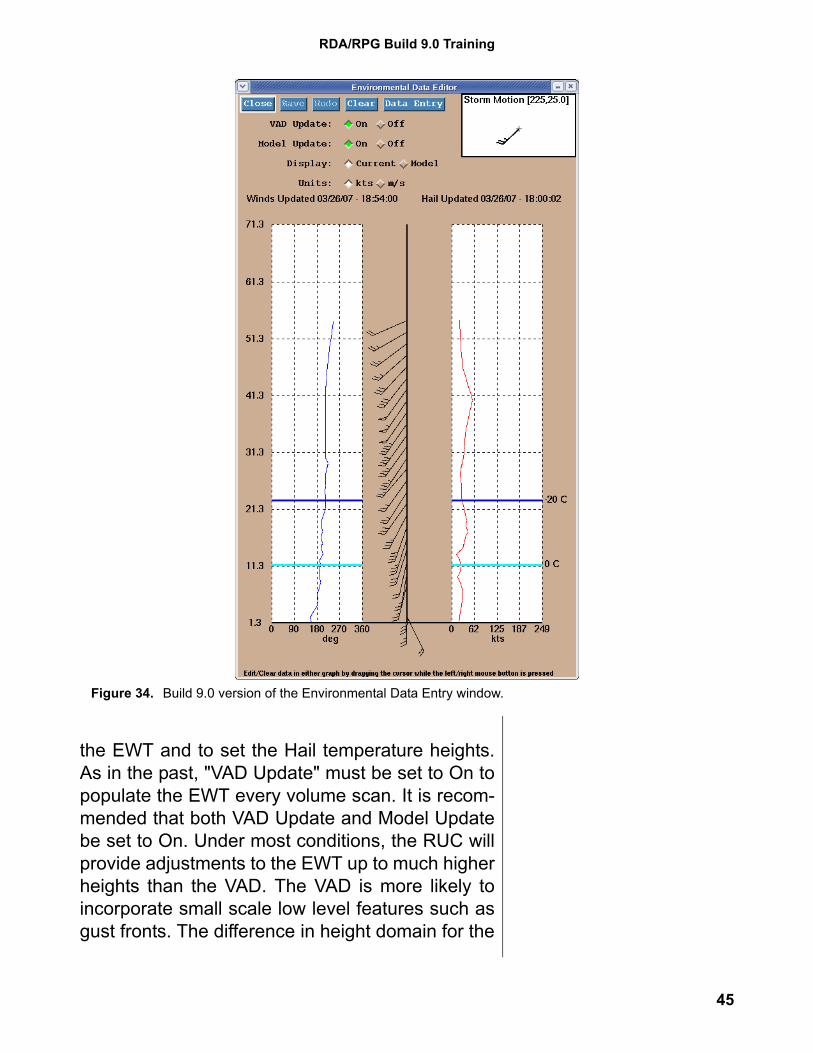
The automated ingest of RUC data results in anumber of changes to the Environmental Data Edi-tor window (Figure 34). “Model Update” must beset to On to allow the hourly RUC data to populate
44
RDA/RPG Build 9.0 Training
the EWT and to set the Hail temperature heights.As in the past, "VAD Update" must be set to On topopulate the EWT every volume scan. It is recom-mended that both VAD Update and Model Updatebe set to On. Under most conditions, the RUC willprovide adjustments to the EWT up to much higherheights than the VAD. The VAD is more likely toincorporate small scale low level features such asgust fronts. The difference in height domain for the
Figure 34. Build 9.0 version of the Environmental Data Entry window.
45
Warning Decision Training Branch
RUC vs. the VAD will usually provide complemen-tary wind profiles for updating the EWT.
The “Display” button allows the operator to viewthe RUC data by selecting “Model”. By selecting“Current”, you can see the current state of theEWT. The Display feature can be used as a qualitycontrol check for the reliability of the RUC data. Ifthe RUC data are not updating or the quality ispoor, ”Model Update” can be set to Off and wind ortemperature data can be edited manually. Thoughthe automatic ingest of model data is very conve-nient, it is important to remember that the VelocityDealiasing Algorithm relies on a representativeEWT. Errors in the RUC data may result in anincrease in dealiasing failures, and will requiremonitoring, and occasional adjustments.
6. Changes to MDA RPG Build 9.0 includes a number of changeswhich move closer to the exclusive use of theMesocyclone Detection Algorithm (MDA) and itsproducts. In the future, the legacy MesocycloneAlgorithm will be removed and the associatedproducts dropped from the suite of available prod-ucts. The document “Mesocyclone DetectionAlgorithm (MDA) Operational Update” providesinformation regarding the implementation of MDA,its relationship to the legacy Mesocyclone algo-rithm and the Build 9.0 changes to MDA. ThisMDA document is available for download from theBuild 9.0 Training web site and the URL will bepresented in the Summary section on page 53.
MDA Background MDA was designed to detect a broad spectrum ofstorm scale circulations. Compared to the legacyMesocyclone Algorithm, MDA detects many morecirculations, including weak, small scale shearregions, as well as larger mesocyclones. It alsoassigns a strength rank to each 3D feature, which
46
RDA/RPG Build 9.0 Training
is a measure of the overall rotation. Dependent onattributes such as base height and depth of thefeature, it is considered either a circulation or a lowcore circulation. If a circulation (low core or not)has a strength rank of 5 or greater, it is considereda mesocyclone. MDA also provides past tracksand forecast positions of circulations and mesocy-clones.
A minimum of two elevation angles is needed forthe 3D correlation of 2D features to identify a cir-culation or a mesocyclone. Low core circulationsor mesocyclones require that the base of the fea-ture be less than 3 km above radar level (ARL).This height requirement will make low core circula-tions or low core mesocyclones less likely at longranges.
MD ProductAn MDA adaptable parameter based on strengthrank, Minimum Display Filter Rank, determineswhich MDA features are displayed on the MDproduct. The default setting for this parameter is 5,meaning that only mesocyclones (low core or not)are displayed. Build 9.0 includes a change thataffects low core mesocyclones (see page 49).Assuming the default parameter setting, a lowcore mesocyclone must have a strength rank of 5or greater and must be within 20 km of a SCIT cellto be displayed on the MD product. MDA featuresare indicated by circles on the MD product. If thecircle has four spikes, the MDA feature includesthe lowest elevation angle.
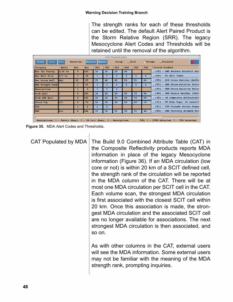
MDA-based AlertingWith Build 9.0, MDA-based Alert Codes andThresholds are available for the Volume and Fore-cast alert groups. The Alert Category is titled MDAStrength Rank and there are six threshold catego-ries. In Figure 35, threshold 1 is set to strengthrank 1, threshold 2 is set to strength rank 2, etc.
47
Warning Decision Training Branch
The strength ranks for each of these thresholdscan be edited. The default Alert Paired Product isthe Storm Relative Region (SRR). The legacyMesocyclone Alert Codes and Thresholds will beretained until the removal of the algorithm.
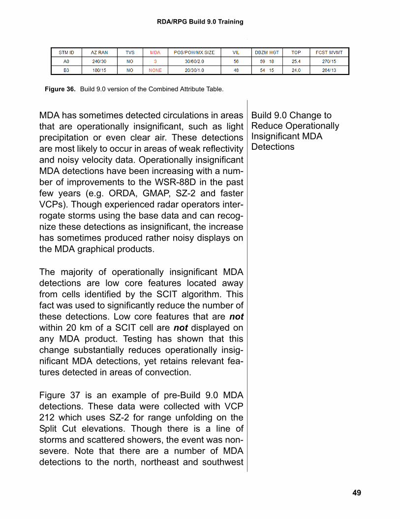
CAT Populated by MDA The Build 9.0 Combined Attribute Table (CAT) inthe Composite Reflectivity products reports MDAinformation in place of the legacy Mesocycloneinformation (Figure 36). If an MDA circulation (lowcore or not) is within 20 km of a SCIT defined cell,the strength rank of the circulation will be reportedin the MDA column of the CAT. There will be atmost one MDA circulation per SCIT cell in the CAT.Each volume scan, the strongest MDA circulationis first associated with the closest SCIT cell within20 km. Once this association is made, the stron-gest MDA circulation and the associated SCIT cellare no longer available for associations. The nextstrongest MDA circulation is then associated, andso on.
As with other columns in the CAT, external userswill see the MDA information. Some external usersmay not be familiar with the meaning of the MDAstrength rank, prompting inquiries.
Figure 35. MDA Alert Codes and Thresholds.
48
RDA/RPG Build 9.0 Training
Build 9.0 Change to Reduce Operationally Insignificant MDA Detections
MDA has sometimes detected circulations in areasthat are operationally insignificant, such as lightprecipitation or even clear air. These detectionsare most likely to occur in areas of weak reflectivityand noisy velocity data. Operationally insignificantMDA detections have been increasing with a num-ber of improvements to the WSR-88D in the pastfew years (e.g. ORDA, GMAP, SZ-2 and fasterVCPs). Though experienced radar operators inter-rogate storms using the base data and can recog-nize these detections as insignificant, the increasehas sometimes produced rather noisy displays onthe MDA graphical products.
The majority of operationally insignificant MDAdetections are low core features located awayfrom cells identified by the SCIT algorithm. Thisfact was used to significantly reduce the number ofthese detections. Low core features that are notwithin 20 km of a SCIT cell are not displayed onany MDA product. Testing has shown that thischange substantially reduces operationally insig-nificant MDA detections, yet retains relevant fea-tures detected in areas of convection.
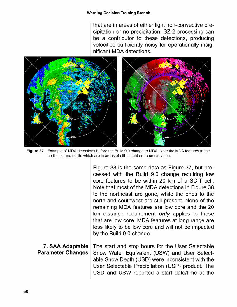
Figure 37 is an example of pre-Build 9.0 MDAdetections. These data were collected with VCP212 which uses SZ-2 for range unfolding on theSplit Cut elevations. Though there is a line ofstorms and scattered showers, the event was non-severe. Note that there are a number of MDAdetections to the north, northeast and southwest
Figure 36. Build 9.0 version of the Combined Attribute Table.
49
Warning Decision Training Branch
that are in areas of either light non-convective pre-cipitation or no precipitation. SZ-2 processing canbe a contributor to these detections, producingvelocities sufficiently noisy for operationally insig-nificant MDA detections.
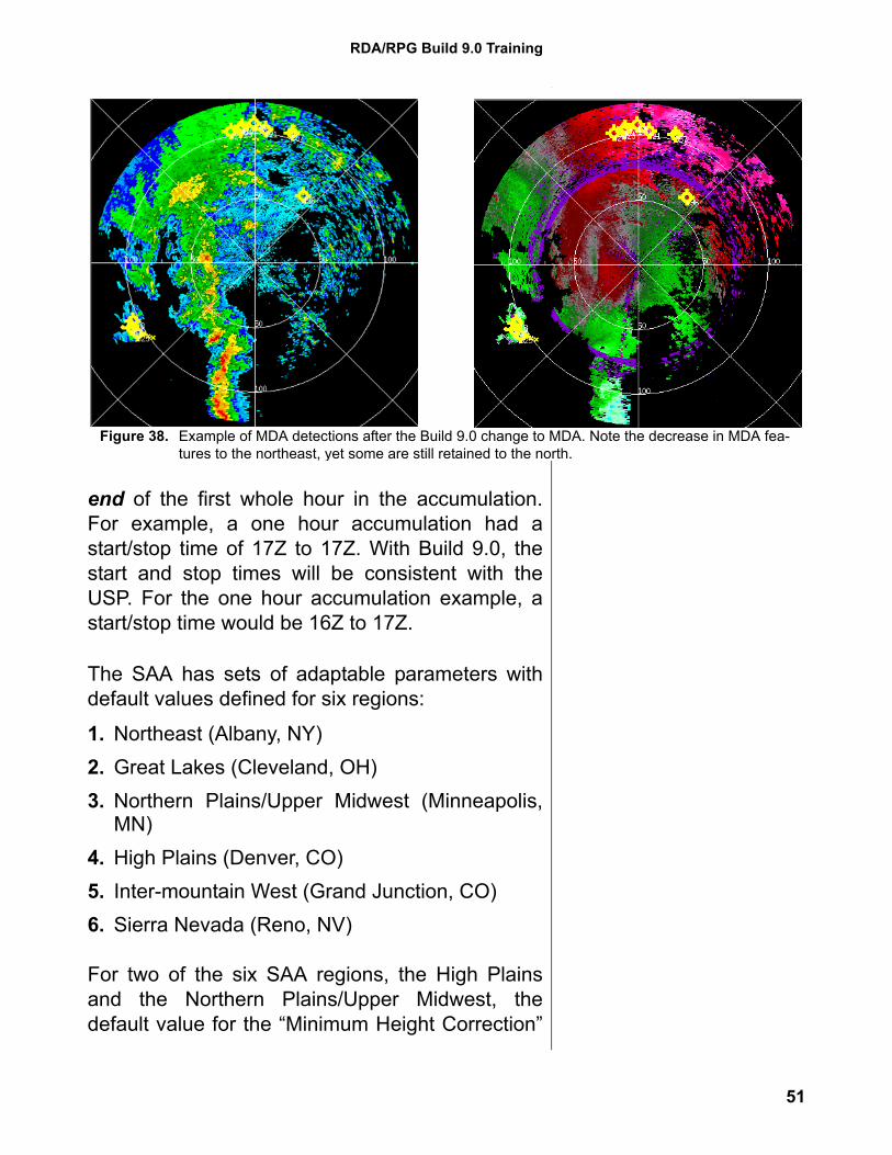
Figure 38 is the same data as Figure 37, but pro-cessed with the Build 9.0 change requiring lowcore features to be within 20 km of a SCIT cell.Note that most of the MDA detections in Figure 38to the northeast are gone, while the ones to thenorth and southwest are still present. None of theremaining MDA features are low core and the 20km distance requirement only applies to thosethat are low core. MDA features at long range areless likely to be low core and will not be impactedby the Build 9.0 change.
7. SAA AdaptableParameter Changes
The start and stop hours for the User SelectableSnow Water Equivalent (USW) and User Select-able Snow Depth (USD) were inconsistent with theUser Selectable Precipitation (USP) product. TheUSD and USW reported a start date/time at the
Figure 37. Example of MDA detections before the Build 9.0 change to MDA. Note the MDA features to the northeast and north, which are in areas of either light or no precipitation.
50
RDA/RPG Build 9.0 Training
end of the first whole hour in the accumulation.For example, a one hour accumulation had astart/stop time of 17Z to 17Z. With Build 9.0, thestart and stop times will be consistent with theUSP. For the one hour accumulation example, astart/stop time would be 16Z to 17Z.
The SAA has sets of adaptable parameters withdefault values defined for six regions:
1. Northeast (Albany, NY) 2. Great Lakes (Cleveland, OH) 3. Northern Plains/Upper Midwest (Minneapolis,
MN) 4. High Plains (Denver, CO)5. Inter-mountain West (Grand Junction, CO)6. Sierra Nevada (Reno, NV)
For two of the six SAA regions, the High Plainsand the Northern Plains/Upper Midwest, thedefault value for the “Minimum Height Correction”
Figure 38. Example of MDA detections after the Build 9.0 change to MDA. Note the decrease in MDA fea-tures to the northeast, yet some are still retained to the north.
51
Warning Decision Training Branch
adaptable parameter has changed from 0.40 km tothe minimum allowable value, 0.01 km. This is theminimum height for applying the range/height cor-rection to S, the rate of snow water equivalent.With the previous setting of 0.40 km, cases havebeen noticed where a discontinuity occurs in theSAA products at the range associated with thisheight.
8. MIGFA MIGFA is an FAA sponsored algorithm designed todetect gust fronts and to provide short term fore-cast positions. The MIGFA products are currentlynot scheduled for any upcoming AWIPS builds, soit is unknown when NWS users would have theopportunity to see them. One place within the RPGHCI windows where MIGFA could be noticed byNWS users is one of the products, “Gust FrontMIGFA”, listed on the Product Generation lists.Also, MIGFA runs on the same processor as theBDDS. If the BDDS is rebooted, there is a NexradMIGFA task failure that will clear itself.
9. Generation of CrossSections in VCP 121
Prior to Build 9.0, Reflectivity Cross Sections(RCS) and Velocity Cross Sections (VCS) couldnot be successfully generated while using VCP121. This problem was related to the additional CDrotations employed at the lower elevations withVCP 121. A Build 9.0 fix allows for the successfulgeneration of both RCS and VCS products in VCP121.
10. VCP Change orDownload Anytime
During a Volume Scan
RPG Build 8.0 introduced the Mode SelectionFunction (MSF), which had a big impact on opera-tions when a VCP Change or Download wasdesired. The MSF still determines the appropriatemode each volume scan, but Build 9.0 removes arestriction with the timing of VCP Changes orDownloads. By looking at the areal coverage ofreturns at 0.5° each volume scan, the MSF deter-
52
RDA/RPG Build 9.0 Training
mines if a Precipitation or Clear Air Mode VCP isneeded. Depending on local settings, the MSFdownloads either the current or a different VCPeach volume scan.
Prior to Build 9.0, it was necessary to be aware ofthe timing of the MSF execution within each vol-ume scan. In order to perform a VCP Change orDownload, the command had to be entered afterthe MSF had run for any given volume scan. Oth-erwise the MSF could have overwritten the VCPcommand.
Build 9.0 removes this restriction. A VCP Changeor Download command can be issued anytimeduring a volume scan. The only exception is if theMSF should command a mode change. For exam-ple, if Precipitation switching is set to Automaticand conditions exceed the thresholds, the MSFwill download the Precipitation Mode Default VCPand it will be in effect next volume scan.
11. Fix to 1° Radial on Rain and Snow Products
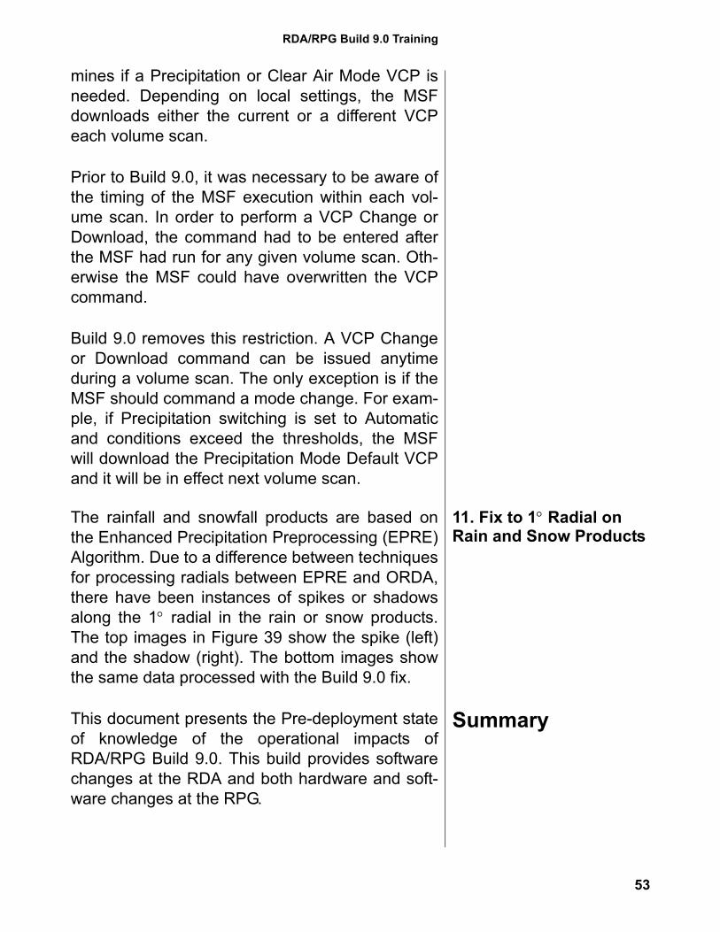
The rainfall and snowfall products are based onthe Enhanced Precipitation Preprocessing (EPRE)Algorithm. Due to a difference between techniquesfor processing radials between EPRE and ORDA,there have been instances of spikes or shadowsalong the 1° radial in the rain or snow products.The top images in Figure 39 show the spike (left)and the shadow (right). The bottom images showthe same data processed with the Build 9.0 fix.
SummaryThis document presents the Pre-deployment stateof knowledge of the operational impacts ofRDA/RPG Build 9.0. This build provides softwarechanges at the RDA and both hardware and soft-ware changes at the RPG.
53
Warning Decision Training Branch
For NWS employees who wish to have completionof this training on their permanent training record,the training presentations (Parts 1 and 2) as wellas the test and survey are available through theNWS Learning Center athttp://doc.learn.com/noaa/nws
The WDTB Build 9.0 Training web site is availableat: http://www.wdtb.noaa.gov/buildTraining/Build9/index.html
Figure 39. Build 9.0 fix for spikes and shadows along 1° radial on rain and snow products.
54

RDA/RPG Build 9.0 Training
Additional copies of this document can be down-loaded from the Build 9.0 Training page. Also, cop-ies of the reference papers listed in this documentare available for download from the Build 9.0page. Finally, there is an opportunity to providefeedback on the effectiveness of this training. Wewelcome your comments!
55

![The Trove [multi]/1st... · PATHFINDER RPG CORE RULEBOOK , PATHFINDER RPG BESTI ARY , PATHFINDER RPG BESTIARY 2 , PATHFINDER RPG BESTIARY 3 , PATHFINDER RPG ADVANCED PLAYER S GUID](https://img.pdfslide.net/doc/110x75/60c7beb87d66ea6048574996/the-trove-multi1st-pathfinder-rpg-core-rulebook-pathfinder-rpg-besti-ary.jpg)