Embed Size (px)
Citation preview

1
RDSwin: Seamlessly-Integrated Aircraft
Conceptual Design for Students & Professionals
AIAA-2016-1277
Daniel P. Raymer1
Conceptual Research Corporation
PO Box 5429, Playa del Rey, CA, USA, 90296-5429
RDSwin is an aircraft conceptual design computer program that includes design layout,
design analysis, and system optimization – the three critical legs of any vehicle design
effort. RDSwin is a single compiled executable that includes an aircraft-oriented Design
Layout Module (CAD) and a full set of aircraft analysis and optimization routines, accessed
from the same pulldown menu and using the same input/output routines. In this paper the
methods and features of RDSwin are presented, with emphasis on those that help justify the
title cliché, “Seamlessly-Integrated.”
Nomenclature A = Aspect Ratio (span2/reference area)
API = Application Programming Interface
CDS = Rockwell Configuration Development System (CAD program)
kB = Kilobyte (103 bytes of information)
fs = Ps per unit fuel flow
L/D = Lift-to-Drag Ratio
M = Mach Number
mB = Megabyte (106 bytes of information)
MDO = Multidisciplinary Design Optimization
Ps = Specific Excess Power
RDSwin = Aircraft design software package (“Raymer’s Design System”)
ROAST = RDS Optimal AeroSpace Trajectories
T/W = Thrust-to-weight ratio
We = Aircraft Empty Weight
Wo = Aircraft Takeoff Gross Weight
W/S = Wing loading (weight/area)
I. Introduction he RDSwin aircraft conceptual design software has been developed to take an aircraft design from first
conceptual layout through functional analysis, leading to performance, range, weight, and cost analysis, and
including design optimization by classic carpet plots and modern MDO. Neither a spreadsheet nor a math package
implementation, RDSwin totals over 88,000 lines of original source code plus 120mB of resource, text, library, and
image files.
RDSwin has its own aircraft-oriented CAD module and includes powerful capabilities for the analysis of
aerodynamics, weights, propulsion, and cost. It has full-capabilities for aircraft sizing, mission analysis, and
performance analysis including takeoff, landing, rate of climb, Ps, fs, turn rate, and acceleration. RDSwin provides
graphical output for drag polars, L/D ratio, thrust curves, flight envelope, range parameter, and more.
1 President, Conceptual Research Corporation. AIAA Fellow.
Copyright © 2016 by D. P. Raymer. All Rights Reserved. Published by the AIAA with author's permission
T
2
RDSwin comes in two versions. The Student version was created to accompany Dr. Raymer’s textbook in the
classroom where it allows the neophyte to rapidly create a credible design and do the required analysis. This frees
up time to learn the overall design process including the all-important design iteration loop. The Professional
version of RDSwin adds greater accuracy and a suite of expert features to help the designer in an industry or
research environment, notably the built-in optimizer, a trajectory module1 (ROAST), automated trade studies, and
IGES geometry export.
Various details of the RDSwin program have been presented previously2,3,4. The sections below will focus upon
the specific methods that tie together design, analysis, optimization, and redesign in a way that can truly be called
“seamlessly-integrated.”
II. One Single Executable The first feature of RDSwin that facilitates its seamless integration is simple – it is all just one big program.
Many such computer programs, including the Rockwell-Boeing IDAS/CDM that this author helped developed
years ago5, are Frankenstein assemblies of separate design, analysis, and optimization programs which were
written by different people at different times for different purposes. These disparate codes are either separate
executables which are brought to the foreground as needed, or are pasted together from their separate parts and
then compiled.
With RDSwin, all of its design layout, analysis, and optimization occurs within a single program executable. It
was all written together, using the same IO subroutines, global memory allocations, resource files, and graphics
utilities. It all uses the same user interface including pulldown menu, on-screen buttons, and expert’s hot keys.
While the word “module” is used in the documentation for differentiating the various portions of the program,
there actually are no separate modules. It’s all one code.
Thus, there is no “throwing it over the wall” from CAD to analysis to optimization because there is no “wall.”
It’s all the same program, defined and developed as an integrated whole. The CAD geometry is directly available
to the analysis and optimization routines since it is read into global variables in the program.
III. User Interface The main user interface is a single pulldown menu with 551 menu and submenu commands. figure 1 shows its
options for component shaping and performance analysis, illustrating that in RDSwin the CAD and analysis are all
part of the same user interface. There are also Windows* pop-up menus and selection boxes for inputs, program
options, and filename selection.
It was decided from the start to provide single keystroke “hotkeys” to speed up program operation by experts.
Regular users get tired of going through several levels in a pulldown menu to do something as simple as graphing
the data already seen on the screen. Each hotkey command can also be done through the pulldown menu, but
pressing a single key is more convenient. Below is a small sample of the available hotkeys:
• P Print
• G Graph current input grid
• H Help (including available hotkeys)
• A Do Analysis
• Z Zoom
• M Measure
• L Locate
• B Save Bitmap of screen
• I Isometric drawing
• R Rendered drawing
• # Toggle between Imperial and Metric Units
Implementing these hotkeys proved troublesome. When a pulldown menu is active, mouse and key inputs are
normally routed to the pulldown menu Windows API routine. To check for the press of a hotkey required
implementing a timer interrupt function to check for a key press throughout the time that the pulldown menu is
waiting for its expected inputs.
* Microsoft®, Internet Explorer®, Excel®, and Windows® are either registered trademarks or trademarks of Microsoft
Corporation in the United States and/or other countries. RDSwin is not a product of, nor is it tested or endorsed by Microsoft.

3
For the input of large amounts of data such as needed for aerodynamic analysis, an all-new input grid routine
was developed for RDSwin. This is directly integrated into the code and is tailor-made for aircraft-oriented data
input. It allows rapid input of required data, automatically sets analysis defaults, and guides the user as to proper
inputs. A portion of a typical input grid is shown as figure 2.
These input grids are either two-variable arrays, such as parasitic drag versus speed and altitude, or are paired
columns of data such as stores drag versus Mach #, or are paired columns of data and labels. The grids are
airplane specific and include pop-up help text for each input column, providing brief explanations and required
units for the data to be entered.
Another aspect of the user interface that facilitates integration both within RDSwin and between it and other
programs is the variety of output formats for analysis results and input file printout. RDSwin lets the user select any
of six different displays, including via other programs such as Excel and MS-Word.
The default option is to show the text on the RDSwin Console (background screen, looks like DOS but it isn’t).
The screen is cleared completely, even the pulldown menu, and the text appears. This provides the maximum
amount of room for text. You can also choose to show the text in a small pop-up box.
Other options send the text to whatever Windows program your computer system identifies as the default for
opening such files. If you select “Use My Word Processor,” RDSwin will create a file with filename extension
.DOC and ask Windows to open it. Windows will start your word processor (usually MS-Word) and open the file.
Similarly, if you select “Use My Spreadsheet,” RDSwin creates an XLS file which most computers will open in
Microsoft Excel.
If you select “Use My Web Browser” then RDSwin will write a complete web page in HTML format and open it
with your browser (Internet Explorer, Firefox, etc…). This is especially useful because resulting web page can be
posted on the Internet or emailed to others. They will be able to see exactly the same results that you see, even if
they don’t have RDSwin.
Note that when RDSwin uses the Web browser for display, it is entirely local to your computer. You don’t need to
have an Internet connection to use your Web browser for display, nor does RDSwin “talk” to the internet on its own.
This ability to write and display a web page of analysis results or input data is actually a remnant of the biggest
mistake made during the years of coding RDSwin. At first, an attempt was made to use HTML code and the user’s
web browser for all data input. A Java utility was written that could read values from HTML Forms from wherever
the data was stored locally on the user’s hard disk. Software was then written to decode the data and load it into
the RDSwin variables and program control parameters.
This worked very nicely and had the advantage of looking like a webpage input form, which everybody is
familiar with (see Error! Reference source not found.). However, a major upgrade to the Windows operating
system at that time changed the disk location of the Forms data. Suddenly, the HTML-based RDSwin input screens
no longer worked! While it was possible to fix it for that Windows release, what about the next one? And the
next?
This seemed too risky, so those ~5,000 lines of code were thrown away. All that was used was the nice routines
that write HTML and “wake up” the user’s web browser. Instead, an all-new RDSwin input grid routine was
created as described above. It’s actually much better than the HTML forms-based input scheme.
IV. Airplane-Oriented Cad The RDSwin Design Layout Module (DLM) is an all-original set of CAD routines developed just for new air
vehicle conceptual design. It is not a separate or linked program as for some other aircraft design packages, nor
was it adapted from a generic CAD program developed for other uses. Despite being called a “Module,” the DLM
is an integral part of RDSwin, being a number of design commands which are coded and compiled with the rest of
RDSwin and called from the same pulldown menu.
The RDSwin CAD geometry is specifically defined to make it easy to manipulate the aircraft configuration, both
through user commands and through automated routines that reconfigure the design based on sizing and
optimization results. Furthermore, the program “knows” what an airplane is, and has automated routines for
quickly creating most of the components used in aircraft design.
A fundamental feature that facilitates initial aircraft design and helps with the integration of design, analysis,
and optimization is its use of “components” as the basic unit of data storage. These are based on standard aircraft
terminology - wing, tail, fuselage, tire, etc… Normally each component represents a single closed object.
Each component in RDSwin has its own local axis system. Its location and orientation within the aircraft global
axis system is readily changed. Each component has a header file with information used in RDSwin to set display

4
options, define component symmetries, record creation date, and other information such as the original reference
geometry for wings and tails.
Each component file includes the actual component geometry which is stored as YZ cross sections stacked in the
X direction, using either point or Bezier representation (see below). Non-planar cross sections are also permitted
for shapes such as a canted inlet front face, like in the F/A-18E/F.
RDSwin components are defined in one of three mathematical formats. The simplest form, often used for internal
components, uses actual surface points stored as cross-section lines. For wings and tails these points are the actual
airfoil coordinates, stretched and scaled using RDSwin routines to create the desired aerodynamic surface geometry.
For a mathematical definition of cross-sections, a variation of the parametric 4th degree polynomial Bezier
Curve is used. This “SuperConic” curve2 looks like a classical conic to the designers, despite its greater power.
Both curves have two endpoints and an on-the-curve shoulder point. Both have lines from the endpoints that
control the tangent angles. The only difference is that in the SuperConic, each endpoint has its own point
controlling tangent direction and they can be placed independently, even on opposite sides of the desired curve.
Also, reflexed curves are permitted unlike in a regular Conic.
Routines in RDSwin make it easy to drag the points around on the screen in cross-section and side/top views.
Point and SuperConic cross-sections can be used to define a component in RDSwin-Student. A third method, the
SuperConic Surface component, is available in RDSwin-Professional. This permits creating true surfaced
components and designing smooth shapes in the longitudinal direction. These three options are shown in figure 4.
RDSwin design data are saved as a simple text file which makes it easy for outside programs to manipulate the
data to redesign the concept. This file format is also very efficient, needed less than 100kB for a typical design in
RDSwin versus about 4mB when the same design is exported as an IGES file.
A typical design example is shown in figure 5, with external and internal components each defined as described
above. The header file and first two cross sections of this design’s fuselage component are as follows, with
explanatory comments in brackets:
RDS-Pro Version win8.2
DanBus2-1.dsn
10-24-2015 {08-01-2014} 09:28:30
D. Raymer
Short-haul Airline & Cargo
DanBus2
0,0,0,0,0,0,0,0 [Wo, Wf, We,..]
Short-haul STOL airliner
{C:Fuselage}
0,0,0,0,0,0 [X,Y,Z,roll,pitch,yaw]
-1,2,0,0,"11111“ [sym,geom,..]
DanBus Fus [user input ID text]
031-000:Fuselage [SAWE code]
08-03-2014
0,0,0,0,0,3 [Wt & cg info]
49.17131 , 3.5 , 7.472312 , 0 , 0
0 , 0 , 0 , 0 , 0 [comp data]
0 , 0 , 0 , 0 , 0 [wing param]
0 , 0 , 0 , 0 , 0
0 , 0 , 0 , 0 , 0
19 pass 2-LD3 [user input text]
13,1,41 [#sect,1=planar,drawpt]
-1.563927,9 [X, # pts]
.0,-1.872008 [Y,Z]
.1856533,-1.872008
.2083588,-1.8921
.245128,-1.904507
.245128,-2.005953
.245128,-2.127892
.2206152,-2.126504
.223155,-2.139899
.0,-2.139899
-.6629171,9 [X, # pts]
.0,9.705202E-2 [Y,Z]
1.529327,9.705202E-2
2.180823,-.1783937
2.845002,-.4527528
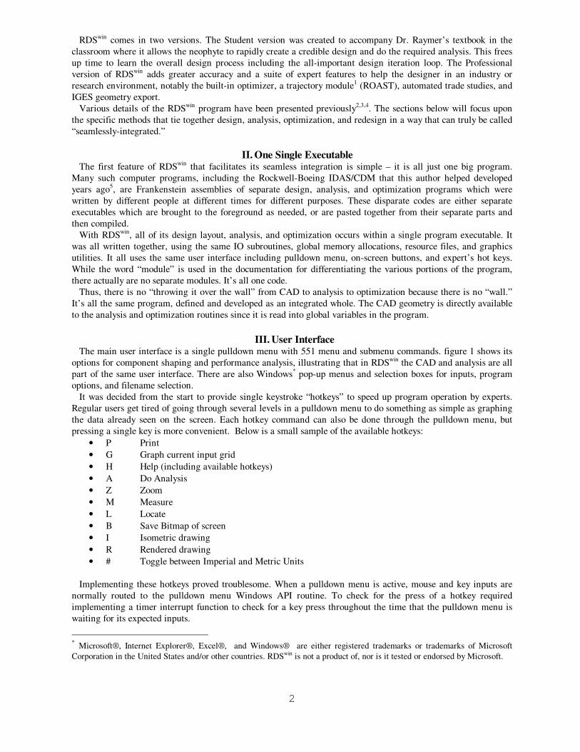
5
2.845002,-1.055454
2.845002,-2.304434
2.164789,-2.862014
1.480262,-3.421194
.0,-3.421194 (plus 11 more sections)
V. Component Type Codes One of the important “seamless integration” features of the RDSwin Design Layout Module is its component type
code scheme. Each component stores a six-digit type code based on the Group Weight Statement categories in
SAWE specification RP8A (previously Mil-Std-1374). This allows RDSwin to “know” which sort of analysis is
appropriate for which components, and which sort of scaling and reshaping logic should be followed when the
user or a sizing/optimization result needs to rescale the whole airplane.
Type codes are defined in the following major categories:
• Wing
• Rotor Tail
• Fuselage
• Landing Gear
• Nacelle & Eng Sect
• Propulsion
• Equipment
• Useful Load
• Non-Physical Comps
For each major category there are specific component type codes, such as these Wing examples:
• 002-000:Ref Wing
• 002-003:LEX
• 002-004:Winglet
• 002-005:Wing Strut
• 002-999:Wing-Other
• 008-000:Aileron
• 008-001:Elevon
• 009-000:Spoiler
• 010-000:Flaps (TE)
• 011-000:Flaps (LE)
• 012-000:Slats
• 031-000:Fuselage
• 031-001:Canopy
• 085-000:Instruments
• 086-000:Hydraulics
• 087-000:Pneumatics
• 088-000:Electrical
• 090-000:Avionics
These are automatically set when using one of the many “canned” component creation routines, or can be
selected in a pick menu. For the full set please contact the author.
For example, when a wing is created the user is prompted to select the type of wing. If 002:000:Ref Wing is
selected, that code is stored with the wing component. When the design is completed and the geometric
information is collected for aerodynamic analysis, RDSwin will recognize from this code that the area of this wing
is to be used as the reference area for the calculated aerodynamic coefficients. Furthermore, the 002:000 code tells
the Weights Module to use a certain wing weight equation, and the code knows which geometric information to
extract from the component to populate the weight analysis input fields.

6
VI. Tab File: Geometry To Analysis Another unique feature to facilitate integration between design, analysis, and optimization is the RDSwin TAB
File. This is a massive tab-delimited file of key design geometric information, and contains wing and tail data
blocks, component information, and component cross section perimeters and areas.
The information for each component includes length, width, height, a-max, l/d-equiv., total surface area, surface
area+ends, total volume, X, Y, Z (location), roll, pitch, yaw, centroids (local and global axis system), and
moments of inertia. The component type code is also listed for each component, allowing the analysis modules to
know what equations to apply. A small portion of a typical TAB file can be seen as figure 6
The TAB File is instantly created by the Analyze command in the Design Layout Module. Then it can be used
to read your design’s geometric information into the Aerodynamics, Weights, and Propulsion modules. When the
TAB file creation is finished, DLM will offer to open it in your spreadsheet for review, and it can be passed to
other members of a project team to answer most of the usual geometric questions about a new design.
VII. Aircraft Data File: User In Charge One unusual feature of the overall structure of RDSwin was deliberately defined to improve the integration
between design, analysis, and optimization. It also makes it easy for the user to do unusual things beyond the
program’s normal methodologies. This refers to the way that a design’s functional analysis results (aero, weights,
and propulsion) get to the performance, range, and sizing calculation routines.
Other papers6 have focused upon the functional analysis methods used within RDSwin. These are mostly based
on calculations described in the author’s textbook Aircraft Design: A Conceptual Approach7.
To provide both integration and flexibility, these functional analysis calculations are NOT done during the
mission sizing and performance calculations. They are done before-hand and stored in a collection of data arrays
called the Aircraft Data File.
The Aircraft Data File is like a filing cabinet. You fill it with data from the Aerodynamics, Weights, and
Propulsion modules, then those numbers are pulled out and used when you run the mission sizing and
performance calculations.
RDSwin works this way for several reasons. When you are calculating something like rate of climb, RDSwin
doesn’t have to recalculate the drag coefficients. It just pulls them out of the “Aero drawer” in the “filing cabinet”.
This is much faster, especially for the big optimizations in RDSwin-Pro.
This program structure also lets you review and approve the analysis results before they are committed to range
and performance calculations. RDSwin facilitates this by stepping through graphs of all the stored data, with a
single pulldown command. And, it’s easy to correct data that you don’t like.
With this method you can quickly do trade studies. Various tools let you scale or change these data items and
then redo the mission sizing and performance calculations. For example, you might multiply the whole parasitic
drag data array by 1.2 to determine the effect on range and rate of climb of a 20% increase in CD0. In a study for
NASA, this was used to create parametric inputs into commercial regression software, resulting in a Response
Surface model for further investigations. The Aircraft Data File approach made this easy.
Finally, this filing cabinet approach lets you “mix and match” your data. You don’t have to use the RDSwin
calculations exclusively. For example, you could type in wind tunnel data for aerodynamics, copy the propulsion
data from a similar aircraft, use RDSwin to estimate the weights, and then use this mash-up to calculate range and
performance.
The Aircraft Data File includes weights data, CD0, K, CL-max, CL-alpha, installed engine thrust, specific fuel
consumption, and certain other parameters. This is all contained in seven separate input grids, mostly in array
format as a function of one or two variables such as velocity and altitude. RDSwin-Pro also permits seven
additional arrays containing part-power specific fuel consumption data, and two more tables defining minimum
thrust.
VIII. Built-In Optimizer The optimization capabilities of RDSwin can be called “seamlessly integrated” because they are built right in to
the code, part of the single executable and accessed through the same pulldown menu. Optimization inputs are
defined in an input grid just like all the other analytical parts of the program, and the various optimization
methods use the same analytical input files that the user has already defined. It literally takes seconds to set up
and run a classic carpet plot, a deterministic stepping search, or a stochastic evolutionary or Genetic Algorithm
optimization.

7
Through the input grid, the user can change various options and defaults including the measure of merit, the
parametric range of the design variables and the real-world constraints that are to be applied (length, span,
volumetric density, etc…).
Note that the RDSwin optimizer is very specific to those design variables with the greatest impact on an overall
aircraft conceptual design, namely T/W and W/S plus the wing trapezoidal planform parameters, i.e., aspect ratio,
taper ratio, sweep, and wing airfoil thickness ratio. Two more variables are included, the fuselage fineness ratio
and the wing design lift coefficient (surrogate for camber optimization).
Measures of Merit for optimization include takeoff gross weight, empty weight, fuel weight, purchase price, life
cycle cost, or internal rate of return. Optimization is done in the face of performance requirements including
takeoff, landing, turn, Ps, climb, and acceleration, with required values defined in the Performance Analysis input
grid.
IX. Automatic Redesign From Sizing And Optimization Results Another uniquely-integrated capability of the RDSwin CAD module is its ability to automatically modify a design
based on the results of sizing analysis and design optimization. This allows the designer to return to the design
layout and instantly see the affect of the changes, and then fix, modify, or reject them as desired.
This automatic redesign is “smart,” using the component type codes described above to change the various
components automatically as appropriate to their type. A wheel doesn’t scale the same way as a wing. The
methods were detailed at a previous AIAA Aerospace Sciences Meeting8 and are summarized below.
The most important result of either sizing or optimization is a new value for the takeoff gross weight. This
changes everything about the design, from the sizes of the wings and tails, to the required engine thrust and inlet
duct diameter, to the wheel diameter and even the height of the aircraft above the ground.
With a normal CAD system the designer will have to spend a lot of time laboriously fixing all these things.
RDSwin does it automatically, using the following rules:
• Fuselage scaled by cube root of weight ratio, unless length constrained by user input
• Wing area scaled proportional to weight ratio
• Tails scaled by 3/2 power then adjusted based on change in fuselage length, to hold constant the tail
volume coefficient
• Engine scaled assuming T/W constant, using empirical exponents for diameter and length vs. thrust ratio
(unless disabled)
• Nacelle and inlet duct scaled in diameter by square root of thrust ratio
• Wheels and tires scaled based on statistical tire diameter and width equations
• Gear shock-strut diameters scaled by square root of weight ratio
• Ground plane and tail-down angle components scaled proportional to fuselage scaling
When a full optimization is done, RDSwin will also automatically change the wing planform and fuselage
geometry to match the new optimized values of wing area, aspect ratio, taper ratio, sweep, airfoil thickness, and
fuselage fineness ratio.
The wing planform revision is done in a parametric manner using mathematics developed by the author that
stretches and slides the actual wing geometry to reflect the difference between the old and new trapezoidal
reference wing. The same is applied to any derived components, such as a wing box, spar, fuel tank, flap, or
aileron. Thus, RDSwin gets the benefits of parametric modeling without the downside limitations on flexibility.
Note that the optimized value for wing design lift coefficient is not directly applied to the geometry. Instead it
becomes a target for the aerodynamic department’s subsequent airfoil shape, twist, and camber optimization. This
is controversial. Some other code developers include such 3-D wing optimization directly within the optimization.
In this author’s opinion it is better to optimize the aerodynamic design target, not attempt to do in a single
computer code what a team of aerodynamic experts will do over a period of months, using high-end CFD tools
and wind tunnel testing.
If volumetric density was used as a constraint, RDSwin will also enlarge the fuselage as needed to maintain
sufficient volume should the wing grow smaller or thinner.
This automatic redesign tool will significantly reduce the time to complete a design iteration going from the
initial “Dash-1” design to the optimized “Dash-2”. Of course, such automatic scaling cannot be expected to
produce perfect revised geometry but it can do most of the “grunt work” associated with revising a design layout
to match the improved design parameters.

8
A re-shaped commercial airliner is shown in figure 8, where area, aspect ratio, taper ratio, and sweep of a wing
have been instantly changed based on optimization results. The non-trapezoidal features of the original wing
design are preserved, scaled proportionally to the changes in the planform parameters. The fuselage fineness ratio
has also been increased as per the optimization, but a minimum diameter constraint was employed. Tail sizes have
been reduced since the longer fuselage has increased their moment arms.
[Note to Students: Sorry, but RDSwin-Student does not have the optimizers or the automatic redesign tools. You
are supposed to be learning how to do such things, not learning how to push a magic button! Instead, RDSwin-
Student makes it easy for students to quickly do all the calculations to graphically construct their own trade
studies and carpet plot graphs. Some universities also get a single copy of RDSwin-Pro that the students can use
after they’ve built their input files in RDSwin-Student.]
X. Design Example Showing Seamless Integration As a sample of the seamless integration between design, analysis, optimization, and redesign, a recent aircraft
design study is presented. This looked at an optionally-manned multirole UAV designed for extensive
modularity†. It has a core vehicle with wings, tails, propulsion, fuselage, and vehicle subsystems. The left side of
the cockpit region is removable and can be replaced with modules providing an extended weapons bay, cannon,
buddy fuel tanks, sensors, and the like. A small portion of the forebody on the right side of the cockpit is not
removable, and carries the nose landing gear and the one-side-only pitch control canard.
After initial sizing, the overall configuration was developed in RDSwin as shown in figure 9. It was designed to a
takeoff gross weight of 12,000 lbs and is 36 feet in length. Note that the CAD file contains multiple components
for the same regions, most notably the cockpit area where a stretched weapons bay is superimposed. These are
modular features, and the airplane would never fly with them all installed.
The geometric information was extracted from the design layout and a TAB file was created, as shown in figure
10. From the TAB file the geometric information needed for analysis was read into the RDSwin input grids for
aerodynamics and weights, with calculation results as shown in figure 11 and figure 12. These results, including
aerodynamics at different speeds and altitudes, were loaded into the Aircraft Data File. For this design, an
already-available installed engine data set was simply copied into the Aircraft Data File so the RDSwin propulsion
module wasn’t used.
Using this data, the aircraft range was calculated over a high-low-high mission, and found to be about 600 nmi
(radius). The cruise altitude and velocity optimization capabilities of RDSwin-Pro were used during this
calculation.
Next, a Carpet Plot (figure 13) was created to review the performance inputs and requirements, and then a
Genetic Algorithm optimization was performed (figure 14).
From the optimization results, the geometry was automatically revised as shown in figure 15. As can be seen,
the optimization reduced wing sweep but increased aspect ratio, and substantially increased fuselage fineness
ratio. These caused a substantial drop in the aircraft TOGW which made the engines and nacelles smaller. With
the greater fuselage fineness ratio, the aft end of the vehicle is no longer lined up! This will have to be fixed.
Luckily, RDSwin still allows a human designer to make the final design decisions!
XI. Summary & Conclusions The architecture and methods of RDSwin have been defined to create a seamless integration between design
layout, design analysis, and system optimization, and thus to allow the designer to focus upon the real job at hand.
The following aspects of the program, methods for which have been described above, are most important:
• Single program EXE with single pulldown menu
• Built-in CAD with airplane-specific design/redesign routines
• Aircraft defined as collection of components with type ID
• Automatic geometric data extraction for analysis (TAB file)
• Changes to design can be auto-updated to analysis input files
• Built-in classical aircraft analysis methods
• Aircraft Data File collects analysis results and allows mix-and-match of data sources, plus scaling and
adjusting of data (“fudging”)
† Permission has been granted by the customer to show this study and reuse its RDSwin design files

9
• Built-in optimizer that can modify design to match its results
RDSwin and its DOS predecessor have been used to design and/or analyze a wide variety of vehicles for
organizations including DARPA, RAND, USAF-AFRL, NASA, Boeing, and Composite Engineering. Vehicle
types include airliners, supersonic stealth fighters, UAVs, airships, personal aircraft, reusable launch vehicles, and
more. Comparisons with known aircraft data has been good, and performance predictions have been validated in
flight.
A key reason for its success to date has been the flexibility and speed of use brought about by the seamless
integration described above.

10
Figures:
figure 1. Single Pulldown Menu for CAD, Analysis, and Optimization
figure 2. Typical RDSwin
Input Grid (Parasitic Drag)

11
figure 3. Use of Webpage Forms for Data Input (discontinued)
figure 4. Three Component Geometry Formats (Point, SC Section, SC Surface)

12
figure 5. Components Defining an Airplane
Component SAWE8 Code Length Width Height A-max l/d-equiv. Total Surface
Area
SurfArea
+Ends
Total
Volume
#
comp
X Y Z Roll Pitch Yaw Xcentroid Xc-global
Wing [002-000] 12.226 10.188 1.047 6.055 4.403 278.869 285.703 66.041 1 20.8 0.0 -1.6 -2.0 0.0 0.0 5.425 21.979
CANOPY [031-001] 23.532 1.832 3.225 4.626 9.696 102.013 102.447 65.282 2 8.1 0.0 2.2 0.0 0.0 0.0 8.001 16.068
Hor Tails [020-001] 6.854 5.957 0.426 1.21 5.522 43.718 45.192 4.661 2 32.7 2.7 -0.4 2.0 0.0 0.0 1.759 32.859
Fuselage [031-000] 34.754 4.2 4.721 17.44 7.375 412.019 413.331 406.078 1 0.0 0.0 0.0 0.0 0.0 0.0 16.685 16.685
Nacelle [055-000] 19.404 3.285 4.054 6.76 6.614 172.836 181.218 115.684 2 15.5 0.0 0.2 0.0 0.0 0.0 9.621 25.082
Main Wheel (down) [040-001] 0.434 1.633 1.633 2.09 0.266 3.168 5.216 0.816 2 23.0 3.2 -3.9 0.0 0.0 0.0 0 23.031
Gear Leg Shockstrut [041-001] 2.971 0.25 0.927 0.13 7.312 2.498 2.519 0.159 2 23.3 2.1 -1.4 -16.8 7.0 0.0 1.074 23.218
Main Wheel Up [040-003] 0.434 1.633 1.633 2.09 0.266 3.168 5.216 0.816 2 20.4 1.4 -1.1 -146.2 0.0 0.0 0 20.38
Nose Wheel [040-002] 0.332 1.249 1.249 1.223 0.266 1.854 3.053 0.365 2 7.9 0.4 -4.0 0.0 0.0 0.0 0 7.925
Nose Shockstrut [041-002] 2.68 0.225 0.225 0.04 11.92 1.785 1.802 0.095 1 8.3 0.0 -0.9 0.0 7.0 0.0 2.117 8.09
Nose Wheel Up [040-003] 0.332 1.249 1.249 1.223 0.266 1.854 3.053 0.365 2 5.7 0.4 -1.2 0.0 0.0 0.0 0 5.702
Nose Shockstrut Up [041-003] 2.68 0.225 0.225 0.04 11.92 1.785 1.802 0.095 1 9.1 0.0 -2.0 0.0 102.9 0.0 2.117 7.041
ACESII SEAT [094-001] 2.005 5.422 3.998 5.818 0.737 37.191 46.514 11.43 1 10.2 0.0 2.5 0.0 -15.0 0.0 0.002 10.374
ACESII SEAT #2 [094-001] 2.005 5.422 3.998 5.818 0.737 37.191 46.514 11.43 1 14.1 0.0 3.2 0.0 -15.0 0.0 0.002 14.274
APG-68 Radar [090-002] 1.588 2.418 1.585 3.006 0.812 10.342 14.968 2.165 1 2.7 0.0 -0.6 0.0 0.0 0.0 0.825 3.501
Williams FJ-44-4 Turbofan [059-000] 5.746 2.168 2.523 4.292 2.458 37.349 38.746 16.916 2 25.8 1.6 0.4 0.0 -0.7 0.0 2.884 28.653
Vert tails [020-003] 6.667 6.571 0.565 2.13 4.049 57.048 59.665 8.1 2 29.8 2.7 1.5 12.0 0.0 0.0 1.997 30.301
figure 6. TAB File (small portion)
figure 7. Optimizer Input Grid

13
figure 8. Automatic Redesign Base On Optimization Results
figure 9. Design Sample – Initial Layout

14
ComponentSAWE8
CodeLength Width Height A-max l/d-equiv.
Total
Surface
Area
SurfArea+
Ends
Total
Volume
#
compX Y Z Roll Pitch Yaw Xcentroid Xc-global
Fuselage [031-000] 36.299 4.714 4.04 13.16 8.868 406.587 406.588 318.584 1 0 0 0 0 0 0 16.863 16.863
Wing [002-000] 9.45 13.247 1.079 9.311 2.744 293.353 304.129 60.764 1 20.24 0 -0.005 3 0 0 4.695 2.144
Williams FJ-44-4 Turbofan [059-000] 5.746 2.168 2.523 4.292 2.458 37.349 38.746 16.916 2 27.26 3.01 -0.635 0 -0.725 0 2.884 30.145
Nacelle [045-001] 17.841 2.934 2.748 5.172 6.953 128.778 128.834 66.855 2 20.21 2.28 -2.148 0 0 0 7.318 27.528
Vert Tails [020-004] 5.933 6.277 0.222 0.528 7.239 42.004 42.686 2.853 2 33.574 4.186 -0.615 25 0 0 2.679 34.008
AIM-120c [158-000] 12.017 1.514 1.514 0.269 20.524 29.184 29.453 2.97 2 18.132 11.711 -0.62 -44 -1 0 6.475 24.605
RightWing Canard [020-002] 3.615 6.024 0.361 1.393 2.715 23.715 25.107 1.696 1 4.939 -2.272 -0.426 -10 0 0 -0.888 5.576
Canard Trunion [020-999] 1.87 0.275 0.275 0.059 6.805 1.326 1.358 0.077 1 5.228 -3.51 -0.643 -10 0 0 1.106 5.228
LauncherRail LAU-128A [031-000] 8.595 0.309 0.507 0.151 19.61 12.628 12.779 1.249 2 20.371 11.3 -0.664 1 -1 0 4.454 24.825
APG-68 Radar [090-002] 1.588 2.418 1.585 3.006 0.812 10.342 14.968 2.165 1 2.676 0 -0.674 0 0 0 0.825 3.501
ACESII SEAT [094-001] 2.005 5.422 3.998 5.818 0.737 37.191 46.514 11.43 1 10.682 0 2.48 0 0 -90 0.002 10.269
Canopy [031-001] 12.365 2.574 2.205 2.565 6.842 61.151 61.157 13.862 1 6.552 0 1.598 0 0 0 4.394 10.946
Nose Wheel [040-002] 0.381 1.436 1.436 1.618 0.266 2.452 4.037 0.556 1 8.565 -1.523 -3.819 0 0 0 0 8.565
Nose Shockstrut [041-002] 2.68 0.225 0.225 0.04 11.92 1.785 1.802 0.095 1 8.989 -1.523 -0.747 0 7 0 2.117 8.731
Nose Shockstrut Up [041-003] 2.68 0.225 0.225 0.04 11.92 1.785 1.802 0.095 1 9.746 -1.523 -1.877 0 106.88 0 2.117 7.72
Main Wheel (down) [040-001] 0.434 1.633 1.633 2.09 0.266 3.168 5.216 0.816 2 23.081 3.22 -3.77 0 0 0 0 23.081
Gear Leg Shockstrut [041-001] 3.22 0.263 0.415 0.086 9.755 2.589 2.683 0.166 2 23.37 1.734 -1.555 -26.3 7 0 0.952 23.265
Main Wheel Up [040-003] 0.434 1.633 1.633 2.09 0.266 3.168 5.216 0.816 2 26.454 0.881 -0.708 -101.2 -30.5 0 0 26.454
GBU-32 Mk83 JDAM 1000lb [158-000] 9.95 1.274 1.274 1.07 8.527 33.237 33.325 7.641 2 9.847 0.753 -1.046 -45 0 0 4.805 14.652
GBU-39 Small Diameter Bomb 285 lbs [158-000] 5.9 0.6 0.6 0.333 9.056 10.896 11.136 1.597 2 13.969 1.023 -0.706 0 0 0 3.359 17.329
Weapons Bay [031-009] 10.544 3.093 1.404 3.402 5.066 82.38 89.12 35.605 1 9.577 0 -1.006 0 0 0 5.245 14.822
GBU-39 Small Diameter Bomb 285 lbs center [158-000] 5.9 0.6 0.6 0.333 9.056 10.893 11.133 1.597 1 13.969 0 -0.706 0 0 0 3.359 17.329
GBU-39 Small Diameter Bomb 285 lbs Fwd [158-000] 5.9 0.6 0.6 0.333 9.056 10.893 11.133 1.597 2 9.722 0.51 -1.309 0 0 0 3.359 13.081
Nose Wheelup [040-002] 0.381 1.436 1.436 1.618 0.266 2.452 4.037 0.556 1 6.354 -1.523 -0.819 0 0 0 0 6.354
Inlet Duct [055-000] 7.453 2.286 2.243 2.451 4.219 41.921 46.527 17.326 2 22.667 3.111 -0.617 0 0 0 1.359 24.026
WingBox [070-000] 11.272 6.862 1.044 2.883 5.883 156.439 160.329 39.519 1 20.24 0 -0.005 3 0 0 4.317 22.867
Gear Leg Shockstrut Up [041-001] 3.22 0.263 0.415 0.086 9.755 2.589 2.683 0.166 2 23.839 1.438 -1.061 -26.3 -100.5 37.5 0.952 24.759
Kestrel LowAlt mod(WAG) [059-000] 3.874 2.374 2.374 4.42 1.633 19.49 23.999 7.19 1 31.463 0 0 0 -1 0 2.39 33.852
Rocket Module Fairing [031-002] 6.485 2.346 2.349 4.316 2.766 46.265 52.567 26.225 1 28.979 0 0.059 0 0 0 2.961 31.94
LOX Tank [071-000] 2.561 2.155 2.155 3.641 1.189 16.06 16.06 6.579 1 29.866 0 0.019 0 0 0 0.203 30.069
Weapons Bay-short [031-009] 6.558 3.093 1.404 3.402 3.151 51.255 57.996 22.16 1 9.577 0 -1.006 0 0 0 7.25 16.827
Fuselage Fuel Tank [070-000] 15.538 4.714 2.407 7.366 5.073 158.481 170.059 80.668 1 0 0 0 0 0 0 20.023 20.023
Fuselage-Cropped [031-000] 35.263 4.714 3.984 13.122 8.627 330.837 330.839 214.713 1 0 0 0 0 0 0 20.978 20.978
Fuselage-ForebodyModule [031-000] 13.264 3.553 4.038 11.024 3.54 134.888 145.912 100.05 1 0 0 0 0 0 0 8.284 8.284
PiTail [020-001] 10 10.994 0.517 1.789 6.625 105.212 107.014 10.079 1 33.998 0 4.675 0 0 0 2.983 -0.807
figure 10. TAB File
figure 11. Aerodynamic Results

15
STRUCTURES GROUP 3406.5 EQUIPMENT GROUP 1989.6
Wing 718.4 Flight Controls 433.2
Horiz. Tail 36.9 Instruments 90.6
Vert. Tail 293.5 Hydraulics 183.5
Fuselage 1492.9 Electrical 445.7
Main Lndg Gear 433.4 Avionics 433.4
Nose Lndg Gear 107.8 Furnishings & Misc 217.6
Engine Mounts 46.3 Air Conditioning 181.7
Firewall 0 Handling Gear 3.8
Engine Section 24.9 APU installed 0
Air Induction 252.4
Misc Empty Weight 400
PROPULSION GROUP 1636.4 We-Allowance 5.0% 371.6
Engine(s) 1300 TOTAL WEIGHT EMPTY 7804.1
Tailpipe 34.1
Engine Cooling 0 USEFUL LOAD GROUP 4195.9
Oil Cooling 69.2 Crew 220
Engine Controls 37 Fuel 3070.9
Starter 18.7 Oil 50
Fuel System 177.5 Payload 855
TAKEOFF GROSS WEIGHT 12000
We/Wo 65.00%
Wf/Wo 25.60%
figure 12. Weights Results
figure 13. Classic Carpet Plot

16
Minimum Baseline Maximum Best
T/W 0.4 0.6 0.8 0.6032
W/S 50 70.838 90 69.683
ASPECT 2.4 3 3.6 3.6
SWEEP 32 40 48 33.016
TAPER 0.16 0.2 0.24 0.1956
t/c 0.064 0.08 0.096 0.0899
Fus l/d 7.102 8.878 10.653 10.653
CL-dsgn 0.4 0.5 0.6 0.4
Sized Wo 11519 10906
Sized We 7586.3 7364.3
Sized Wf 2807.8 2416.9
Perf: Required Baseline Best
Takeoff 2500 2507.6 2466.7
Landing 3200 3035.7 3003.7
Ps@n 0 6.655 23.346
Ps@n 0 -9.783 5.883
InstTurn 12 12.309 12.517
figure 14. Genetic Algorithm Optimization
figure 15. Optimization-Revised Layout

17
References 1 Raymer, D., "Trajectory Scripts for Aircraft and Spacecraft Flight Path Analysis", AIAA Paper 2016-(tbd),
AIAA Aerospace Sciences Meeting, San Diego, CA, 2016 (submitted for publication)
2 Raymer, D.,"Conceptual Design Modeling in the RDS-Professional Aircraft Design Software", AIAA Paper
2011-0161, AIAA Aerospace Sciences Meeting, Orlando, FL, 2011
3 Raymer, D., "Vehicle Scaling Laws for MultiDisciplinary Optimization", AIAA Paper 2001-0532, AIAA
Aerospace Sciences Meeting, Reno, NV, Jan. 2001
4 Raymer, D., "Use of Net Design Volume to Improve Optimization Realism",Weight Engineering Journal Vol
61 #2, Society of Allied Weight Engineers, Spring 2002
5 Raymer, D., "CDS Grows New Muscles", Astronautics and Aeronautics (Aerospace America), June 1982
6 Raymer, D., "RDS-Professional in Action: Aircraft Design on a Personal Computer", SAE/AIAA Paper
965567, Oct. 1996
7 Raymer, D., Aircraft Design: A Conceptual Approach, American Institute of Aeronautics and Astronautics,
Washington, D.C., 1989 (5th Edition 2012)
8 Raymer, D., “Automatic Aircraft Configuration Redesign - the Application of MDO Results to a CAD File”,
AIAA Aerospace Sciences Meeting Paper 2009-1659 (oral), Reno, NV, 2009


![RDS 323 Restorative Dental Sciences [ RDS]](https://img.pdfslide.net/doc/110x75/6235ee36aafa9c66c73cc0cf/rds-323-restorative-dental-sciences-rds.jpg)