Embed Size (px)
Citation preview

RE 48110, edition: 2015-03, Bosch Rexroth AG
Manifolds
Features
▶ Base element for ready-for-connection controls in vertical stacking design
▶ Compact hydraulic controls ▶ Common pump line ▶ Common tank line ▶ Separate actuator ports of the stations ▶ Optional measuring ports in the actuator lines ▶ Mounting of size 10 sandwich plates and valves ▶ Mounting of size 6 sandwich plates and valves possible
by means of an additional adapter plate
▶ Size 10 ▶ Component series 15 and 35 ▶ Maximum operating pressure 315 bar ▶ 1 to 8 stations
Type HSR 10RE 48110 Edition: 2015-03Replaces: 05.13
Contents
Features 1Ordering code, description 2Standard program 3, 4Technical data , switching symbols 5Dimensions 6 ... 13Manifold configurator 14Mounting screws 15Project planning information 16Selection of possible subplate-mounted valves 17Required ordering code of a completely mounted manifold 17

2/18 HSR 10 | Manifolds
Bosch Rexroth AG, RE 48110, edition: 2015-03
Ordering code
Number of ready-for-connection controls in vertical stacking design01 1 control 1
2 controls 23 controls 34 controls 4
5 controls 56 controls 67 controls 78 controls 8
02 Manifold HSR
03 Size 10 10
Component series04 Port size: A, B = G1/2"; P, T = G3/4" 15
With enlarged connection thread: Port size: A, B = G3/4"; P, T = G1" 35
Connection thread05 Pipe thread according to ISO 228 Part 1 01
Position of actuator ports06 Lateral C
Bottom D
Versions07 Standard no code
With measuring ports in A and B SO8 1)
Coating08 Phosphated DIN EN 12476 PHOSPHATED 2)
Galvanic coating DIN 50979 FE//ZN8//CN/T0
01 02 03 04 05 06 07 08
Manifold HSR 10 ― / 01
1) Not possible with series 15 with lateral actuator ports2) Standard version (manganese or zinc phosphating)
Description
▶ Manifolds are the base element for ready-for-connection controls in vertical stacking design
▶ Manifolds of size 10 are available with 1 to 8 stations ▶ On each station, highly compact hydraulic controls can
be built using vertically stackable sandwich plate valves in conjunction with shift valves or proportional servo valves of size 10 or size 6 (adapter plate required)
▶ All stations have a common pump port and a common tank port
▶ The pump line “P” and the tank line “T” are lead through the two front sides of the manifold
▶ Every station is equipped with separate actuator ports “A” and “B”
▶ Actuator ports are either located at the bottom or laterally
▶ Another option are measuring ports in the actuator channels “A” and “B”

Manifolds | HSR 10 3/18
RE 48110, edition: 2015-03, Bosch Rexroth AG
Mea
suri
ng p
ort
Num
ber
of
stat
ions
Port
siz
e A
, B
Port
ing
patt
ern
A, B
Port
siz
e P,
T
Type key Manifold... Material number
Wei
ght
in k
g
MKZ1)
without 1 G1/2" lateral G3/4" 1HSR10-15/01C PHOSPHATED R900815073 6.4 A3
2
G1/2"lateral
G3/4"2HSR10-15/01C PHOSPHATED R900154881 8.2 A2
bottom 2HSR10-15/01D PHOSPHATED R900158686 9.4 A2
G3/4"lateral
G1"2HSR10-35/01C PHOSPHATED R900170962 12.5 A2
bottom 2HSR10-35/01D PHOSPHATED R900170967 11.4 A3
3
G1/2"lateral
G3/4"3HSR10-15/01C PHOSPHATED R900154882 12.5 A3
bottom 3HSR10-15/01D PHOSPHATED R900158687 12.4 A2
G3/4"lateral
G1"3HSR10-35/01C PHOSPHATED R900170963 15.7 A2
bottom 3HSR10-35/01D PHOSPHATED R900170968 14.4 A3
4
G1/2"lateral
G3/4"4HSR10-15/01C PHOSPHATED R900154883 16.8 A3
bottom 4HSR10-15/01D PHOSPHATED R900158688 19.2 A2
G3/4"lateral
G1"4HSR10-35/01C PHOSPHATED R900170964 21.1 A3
bottom 4HSR10-35/01D PHOSPHATED R900170969 23.3 A3
5
G1/2"lateral
G3/4"5HSR10-15/01C PHOSPHATED R900154884 24.8 A3
bottom 5HSR10-15/01D PHOSPHATED R900158689 20.6 A3
G3/4"lateral
G1"5HSR10-35/01C PHOSPHATED R900170965 32 A3
bottom 5HSR10-35/01D PHOSPHATED R900170970 29.2 A2
6
G1/2"lateral
G3/4"6HSR10-15/01C PHOSPHATED R900154885 29.9 A3
bottom 6HSR10-15/01D PHOSPHATED R900158690 29 A3
G3/4"lateral
G1"6HSR10-35/01C PHOSPHATED R900170966 38.4 A3
bottom 6HSR10-35/01D PHOSPHATED R901406308 29.4 A3
7
G1/2"lateral
G3/4"7HSR10-15/01C PHOSPHATED R901406300 30 A3
bottom 7HSR10-15/01D PHOSPHATED R901406303 29 A3
G3/4"lateral
G1"7HSR10-35/01C PHOSPHATED R900809787 37.9 A3
bottom 7HSR10-35/01D PHOSPHATED R900809788 34.2 A3
8
G1/2"lateral
G3/4"8HSR10-15/01C PHOSPHATED R901406301 34.1 A3
bottom 8HSR10-15/01D PHOSPHATED R901406304 40 A3
G3/4"lateral
G1"8HSR10-35/01C PHOSPHATED R901406305 44 A3
bottom 8HSR10-35/01D PHOSPHATED R901406309 47 A3
1) Material mark; A2 = preferred; A3 = standard;
Standard program including preferred types: HSR10
Order example for a manifold with galvanic coating:Manifold 6HSR10-35/01D FE//ZN8//CN/T0

4/18 HSR 10 | Manifolds
Bosch Rexroth AG, RE 48110, edition: 2015-03
Mea
suri
ng p
ort
Num
ber
of
stat
ions
Port
siz
e A
, B
Port
ing
patt
ern
A, B
Port
siz
e P,
T
Type key Manifold... Material number
Wei
ght
in k
g
MKZ1)
with
1
G1/2" bottom G3/4" 1HSR10-15/01D SO8 PHOSPHATED R901406693 5 A3
G3/4"lateral
G1"1HSR10-35/01C SO8 PHOSPHATED R900815075 5.8 A2
bottom 1HSR10-35/01D SO8 PHOSPHATED R900815076 7.3 A3
2
G1/2" bottom G3/4" 2HSR10-15/01D SO8 PHOSPHATED R901406694 7.9 A3
G3/4"lateral
G1"2HSR10-35/01C SO8 PHOSPHATED R900689383 10.1 A2
bottom 2HSR10-35/01D SO8 PHOSPHATED R900196376 11.4 A3
3
G1/2" bottom G3/4" 3HSR10-15/01D SO8 PHOSPHATED R901406696 12.1 A3
G3/4"lateral
G1"3HSR10-35/01C SO8 PHOSPHATED R900689384 15.5 A3
bottom 3HSR10-35/01D SO8 PHOSPHATED R900196377 18.8 A3
4
G1/2" bottom G3/4" 4HSR10-15/01D SO8 PHOSPHATED R901406697 16.3 A3
G3/4"lateral
G1"4HSR10-35/01C SO8 PHOSPHATED R900689385 25.5 A3
bottom 4HSR10-35/01D SO8 PHOSPHATED R900196378 19.1 A2
5
G1/2" bottom G3/4" 5HSR10-15/01D SO8 PHOSPHATED R901406700 20.5 A3
G3/4"lateral
G1"5HSR10-35/01C SO8 PHOSPHATED R900689386 28 A3
bottom 5HSR10-35/01D SO8 PHOSPHATED R901406310 24.1 A3
6
G1/2" bottom G3/4" 6HSR10-15/01D SO8 PHOSPHATED R901406701 24.7 A3
G3/4"lateral
G1"6HSR10-35/01C SO8 PHOSPHATED R900689387 38.4 A3
bottom 6HSR10-35/01D SO8 PHOSPHATED R900196380 35.2 A3
7
G1/2" bottom G3/4" 7HSR10-15/01D SO8 PHOSPHATED R901406702 33.9 A3
G3/4"lateral
G1"7HSR10-35/01C SO8 PHOSPHATED R901406306 37.3 A3
bottom 7HSR10-35/01D SO8 PHOSPHATED R901406311 34 A3
8
G1/2" bottom G3/4" 8HSR10-15/01D SO8 PHOSPHATED R901406703 33 A3
G3/4"lateral
G1"8HSR10-35/01C SO8 PHOSPHATED R901406307 42.2 A3
bottom 8HSR10-35/01D SO8 PHOSPHATED R901406312 38.8 A3
1) Material mark; A2 = preferred; A3 = standard;
Standard program including preferred types: HSR10...SO8
Order example for a manifold with galvanic coating:Manifold 5HSR10-35/01D SO8 FE//ZN8//CN/T0

Manifolds | HSR 10 5/18
RE 48110, edition: 2015-03, Bosch Rexroth AG
Technical data (For applications outside these parameters, please consult us!)
GeneralSize 10Material GGG40Surface coating Standard coating: Phosphated 1) according to DIN EN 12476
with finishing treatment (greases, oils, lubricants)Maximum operating pressure 2) bar 315
Note!For assembly, commissioning and maintenance of oil hydraulic systems please observe the data sheet 07900!
Switching symbols for manifolds with 4 stations
Manifold HSR10-15/01C
Manifold HSR10-15/01D
Manifold HSR10-15/01D SO8
Manifold HSR10-35/01C
Manifold HSR10-35/01C SO8
Manifold HSR10-35/01D
Manifold HSR10-35/01D SO8
1) Manganese or zinc phosphating
�� �� �� �� �� �� �� ������
�������������� ����
����
�� �� �� �� �� �� �� ������
�������������� ����
����
�� ��
����
���� ��������
��� ��� �� ����� ��� �� ����� ��� �� ����� ���
������������
����������
�� �� �� �� �� �� �� ������
������������ ��
����
�� �� �� �� �� �� �� ������
������������ ��
����
�� ��
����
�� ������
��� ��� �� ����� ��� �� ����� ��� �� ����� ���
������������
����������
�� ��
����
�� ������
��� ��� �� ����� ��� �� ����� ��� �� ����� ���
������������
����������
2) Manifold without valve fitting!
6/18 HSR 10 | Manifolds
Bosch Rexroth AG, RE 48110, edition: 2015-03
Number of sta-tions
Overall length L
Fixing holes
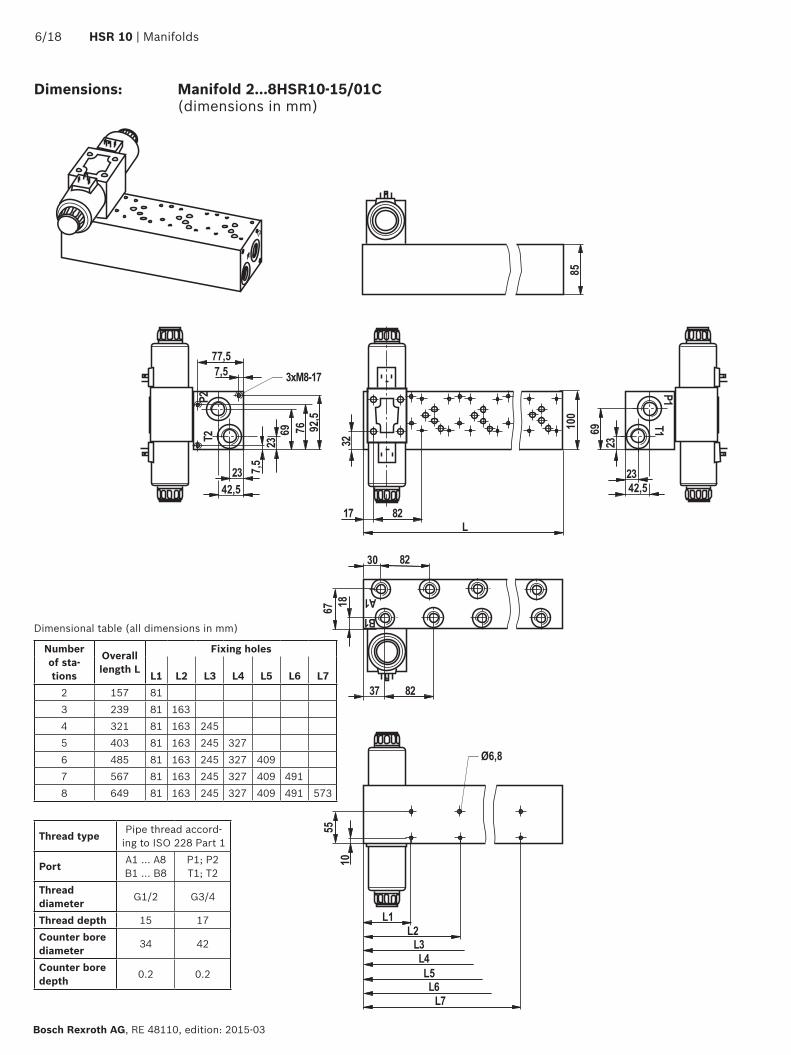
L1 L2 L3 L4 L5 L6 L72 157 813 239 81 1634 321 81 163 2455 403 81 163 245 3276 485 81 163 245 327 4097 567 81 163 245 327 409 4918 649 81 163 245 327 409 491 573
Dimensional table (all dimensions in mm)
Thread type Pipe thread accord-ing to ISO 228 Part 1
Port A1 ... A8 B1 ... B8
P1; P2 T1; T2
Thread diameter G1/2 G3/4
Thread depth 15 17Counter bore diameter 34 42
Counter bore depth 0.2 0.2
Dimensions: Manifold 2...8HSR10-15/01C (dimensions in mm)
��
��� �������
������
��
��
��
�� ���
���
������
����
������
��
�� ��
�� ��
����
����
��������������
����
���
�
��
� ���
�� ��

Manifolds | HSR 10 7/18
RE 48110, edition: 2015-03, Bosch Rexroth AG
Dimensions: Manifold 2...8HSR10-15/01D (without measuring ports MA, MB) Manifold 2...8HSR10-15/01D SO8 (with measuring ports MA, MB) (dimensions in mm)
Number of sta-tions
Overall length L
Fixing holes
L1 L2 L3 L4 L5 L6 L72 157 813 239 81 1634 321 81 163 2455 403 81 163 245 3276 485 81 163 245 327 4097 567 81 163 245 327 409 4918 649 81 163 245 327 409 491 573
Dimensional table (all dimensions in mm)
Thread type Pipe thread according to ISO 228 Part 1
Port A1 ... A8 B1 ... B8
P1; P2 T1; T2
MA1...MA8MB1...MB8
Thread diameter G1/2 G3/4 G1/4
Thread depth 15 17 13Counter bore diameter 34 42 25
Counter bore depth 0.2 0.2 0.2
�����
�� ��
��
����
�������
��
��
����
�� ���
��
�� ���
��
���
��
����
����
����
�����
�� ��
�� ��
����
����
��
��
�� �
��������������
�� ��

8/18 HSR 10 | Manifolds
Bosch Rexroth AG, RE 48110, edition: 2015-03
Dimensions: Manifold 2...8HSR10-35/01C (without measuring ports MA, MB) Manifold 2...8HSR10-35/01C SO8 (with measuring ports MA, MB) (dimensions in mm)
Number of sta-tions
Overall length L
Fixing holes
L1 L2 L3 L4 L5 L6 L72 157 813 239 81 1634 321 81 163 2455 403 81 163 245 3276 485 81 163 245 327 4097 567 81 163 245 327 409 4918 649 81 163 245 327 409 491 573
Dimensional table (all dimensions in mm)
Thread type Pipe thread according to ISO 228 Part 1
Port A1 ... A8 B1 ... B8
P1; P2 T1; T2
MA1...MA8MB1...MB8
Thread diameter G3/4 G1 G1/4
Thread depth 17 19 13Counter bore diameter 42 47 25
Counter bore depth 0.2 0.2 0.2
���
��
����
���
����
�������
����
��
�� ��
�� ���
��
��
�� �� ��
��
����
��
��
���� ��
�� ��
���
���
��������������
���
������
���
�� ��
��
��

Manifolds | HSR 10 9/18
RE 48110, edition: 2015-03, Bosch Rexroth AG
Dimensions: Manifold 2...8HSR10-35/01D (without measuring ports MA, MB) Manifold 2...8HSR10-35/01D SO8 (with measuring ports MA, MB) (dimensions in mm)
Number of sta-tions
Overall length L
Fixing holes
L1 L2 L3 L4 L5 L6 L72 157 813 239 81 1634 321 81 163 2455 403 81 163 245 3276 485 81 163 245 327 4097 567 81 163 245 327 409 4918 649 81 163 245 327 409 491 573
Dimensional table (all dimensions in mm)
Thread type Pipe thread according to ISO 228 Part 1
Port A1 ... A8 B1 ... B8
P1; P2 T1; T2
MA1...MA8MB1...MB8
Thread diameter G3/4 G1 G1/4
Thread depth 17 19 13Counter bore diameter 42 47 25
Counter bore depth 0.2 0.2 0.2
�������
���� ��
��
����
�������
��
��
����
�����
��
�� ���
����
�
��
����
����
��
��
���
����
���� ��
���� ��
���� �
���
��
��
����
��������������

10/18 HSR 10 | Manifolds
Bosch Rexroth AG, RE 48110, edition: 2015-03
Dimensions: Manifold 1HSR10-15/01C (dimensions in mm)
Thread type Pipe thread according to ISO 228 Part 1Port A; B P1; P2; T1; T2Thread diameter G1/2 G3/4
Thread depth 15 17Counter bore diameter 34 42
Counter bore depth 0.2 0.2
����
�� ��
�����
���
������
����
����
�
����
��
�
��
��
��
��
�� ��
����
���
����
�������
�� ��

Manifolds | HSR 10 11/18
RE 48110, edition: 2015-03, Bosch Rexroth AG
Dimensions: Manifold 1HSR10-15/01D SO8 (dimensions in mm)
Thread type Pipe thread according to ISO 228 Part 1Port A; B P1; P2; T1; T2 MA; MBThread diameter G1/2 G3/4 G1/4
Thread depth 15 17 13Counter bore diameter 34 42 25
Counter bore depth 0.2 0.2 0.2
��
�� ��
�����
���
��
��
��
��
��
��
��
����
�� ��
��
��
���
�
��
��
��
�������
����
�
�
��
�
��
��
��
��

12/18 HSR 10 | Manifolds
Bosch Rexroth AG, RE 48110, edition: 2015-03
Dimensions: Manifold 1HSR10-35/01C SO8 (dimensions in mm)
Thread type Pipe thread according to ISO 228 Part 1Port A; B P1; P2; T1; T2 MA; MBThread diameter G3/4 G1 G1/4
Thread depth 17 19 13Counter bore diameter 42 47 25
Counter bore depth 0.2 0.2 0.2
��
��
��
����
��
��
�� ��
����
��
�
��
����
��
�
��
����
��
��
���
��
���
��
����
�������
�� ���
�� ��
�
Manifolds | HSR 10 13/18
RE 48110, edition: 2015-03, Bosch Rexroth AG
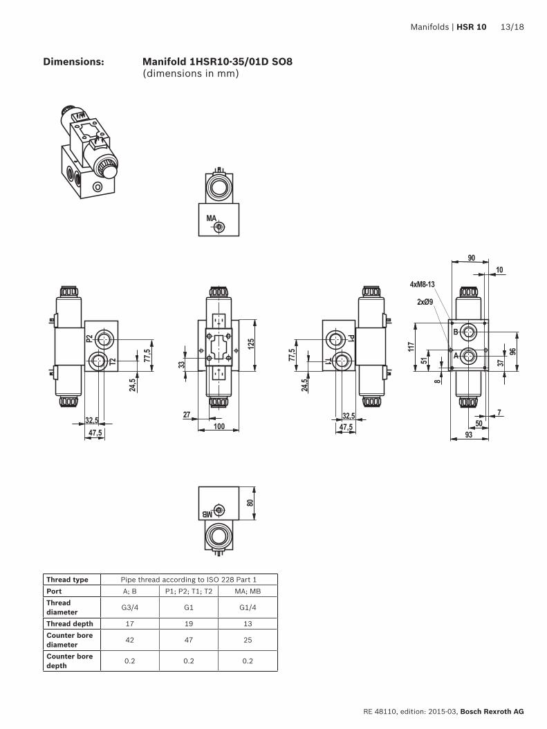
Dimensions: Manifold 1HSR10-35/01D SO8 (dimensions in mm)
Thread type Pipe thread according to ISO 228 Part 1Port A; B P1; P2; T1; T2 MA; MBThread diameter G3/4 G1 G1/4
Thread depth 17 19 13Counter bore diameter 42 47 25
Counter bore depth 0.2 0.2 0.2
����
����
��
�����
���
����
��
��
��
��
����
��
����
����
��������
��
��
���
���
����
�������
����
��
�
�
�
���
��

14/18 HSR 10 | Manifolds
Bosch Rexroth AG, RE 48110, edition: 2015-03
The configurator for HSR manifolds helps you configure your individual manifold or HSH vertical stacking in a simple and convenient way.You can do this online by selecting relevant features of the base element (e.g. size, number of stations and port size) and the mounted product components (e.g. size, pressure settings, type of actuation).
The manifold configurator on www.boschrexroth.com/ics/hsr
Thanks to the intuitive menu navigation, you are guided safely through the required configuration steps. Related features are clearly arranged on one page.By connecting components from various product areas, you can choose from a range of approx. 1000 different functions.
The individual components are selected either by type key or by material number using a configuration based on the circuit diagram or a “step by step” selection of the individual functional properties of the valve or the sandwich plate.
When the configuration is complete, a collision check offers various possibilities of fixing existing collisions.When the configuration is finished, you can have the complete configuration documentation sent to you via email including material list, circuit diagram, 2D draw-ing and 3D model (STEP). This is done by way of an automatic request to your local distributor who will promptly contact you and send you an offer.
Note: ▶ You cannot use it for unfitted plates!

Manifolds | HSR 10 15/18
RE 48110, edition: 2015-03, Bosch Rexroth AG
Mounting screws depending on valve fitting
Number of sandwich plates
Clamping lengths of sandwich plates
Hexagon socket head cap screws according to ISO 4762; stud screws
according to DIN 939
Stability Material no.
1 1 x 50 mm M6 x 90 ISO 4762 10.9 R9130002592 2 x 50 mm M6 x 140 ISO 4762 10.9 R9130004433 3 x 50 mm M6 x 190 DIN 939 10.9 R9000149684 4 x 50 mm M6 x 240 DIN 939 10.9 R900024864
5 5 x 50 mm M6 x 295 DIN 939 10.9 R900012024For the torques of the screws, please refer to the corresponding data sheets of the valves
Screw selection table for vertical stacking in combination with size 10 directional valves
Example for mountable sandwich plates with a clamping length of 50 mm:Pressure reducing valve ZDR 10 D...-5X/..., pressure relief valve ZDB 10 V...-4X/..., double check valve Z2S 10...-3X/..., check valve Z1S10...-.../, double throttle check valve Z2FS 10...-3X/V, pressure switch with sandwich plate HED 8 OH2X/...
Directional valve Hexagon socket head cap screws according to ISO 4762;
Stability Material no.
direct operated directional valve WE 10 M6 x 40 ISO 4762 10.9 R913000058pilot operated directional valve WEH 10 M6 x 45 ISO 4762 10.9 R913000258
direct operated proportional valve WRA 10, WRE 10 M6 x 40 ISO 4762 10.9 R913000058pilot operated proportional valve WRK 10, WRZ 10 M6 x 45 ISO 4762 10.9 R913000258
For the torques of the screws, please refer to the corresponding data sheets of the valves
Note! ▶ The screw selection table does not apply to direc-
tional valves in their seawater-protected version due to differences in the clamping lengths on the direc-tional valve (dimensions see data sheets – seawater-protected directional valves).
Note! ▶ Directional valves with central ports “D”, “DL”, “DZ”
and “DZL” can only be used with hexagon socket head cap screws or stud screws and round nut according to ZN 10035, material no. R913020310.
Stud screw M6 DIN 939, property class 10.9
������������
���
��
��
��
L see screw selection table
��
��
����
��
����
Round nut ZN10035-M6-ST, material no. R913020310
Note! ▶ The clamping lengths of the mounted sandwich plates
and valves must be checked for each individual case.

16/18 HSR 10 | Manifolds
Bosch Rexroth AG, RE 48110, edition: 2015-03
Project planning information
Pressure reducing valve in conjunction with double check valve The pressure reducing valve ZDR..DA (pressure reduc-tion in channel A) must always be installed between the directional valve and the double check valve Z2S... This ensures that the double check valve can block in a leak-free manner.
Pressure relief valve in connection with double check valve Leak-free blocking of the actuator is not possible if a pressure relief valve ZDB../Z2DB.. is effective in channel A and/or B and a double check valve is installed.
Note!The installation of sandwich plates with two pressure switches on manifolds with lateral ports “C” is not possible.
Supply controlThe pressure switch HED 8 OH, effective in channel A and/or B, is installed between the sub-plate and the twin throttle check valve Z2FS.
Discharge controlThe pressure switch HED 8 OH, effective in channel A and/or B, is installed between the direc-tional valve and the twin throttle check valve Z2FS.
� � � �
� � � ��
� � � �
� �
��
� � � �
� � � �
� � � �
� �
��
� � � �
� � � �
� � � �
� �
��
� � � �
� � � �
� � � �
� �
��
The illustrated sections of circuit diagrams are examples. The project planning information must also be observed for valves with a similar function.
Sandwich plate (with or without separate port X, Y) for use with pilot operated valve
Note!To seal channels X and Y on manifold version “C” (lateral actuator ports), you need the sandwich plate with material no. R900320784 (NBR) or R900321346 (FKM)!
Note!For all designs, the external pilot oil supply is only possible with the sandwich plate with material no. R900320785 (NBR) or R900321347 (FKM)!
1) Plate clamping length
� � ��
������
� � ��
����
����
����
����
����
����
Pressure switches in connection with twin throttle check valve

Manifolds | HSR 10 17/18
RE 48110, edition: 2015-03, Bosch Rexroth AG
Selection of available subplate-mounted valves
Sandwich plates size 10 Data sheetSandwich plates HSZ 48052
Pressure reducing valve ZDR 26585Pressure relief valve ZDB 25761Double check valve Z2S 21553
Check valve Z1S 21537Twin throttle check valve Z2FS 27518
Pressure switch HED8 50061
Directional valves size 10 Data sheetWE (electrically operated) 23327
WM, WP, WHD and WN (mechanically, manually, fluidically operated)
22331
WEH (pilot operated) 24751 1)
Proportional valves size 10 Data sheetWRA (direct operated, without feedback) 29055WRE (direct operated, with el. feedback) 29061
WRZ/WRH (pilot operated without feedback) 29115 1)
1) Observe the notes on page 16
Adapter plate size 10 Data sheetHSE 48045
Cover plate size 10 Data sheetHSA 48042
If adapter plates are used, valves of other sizes can also be mounted.
NG = size
Required ordering code of a completely mounted manifoldExample:2-fold manifold
��
��
�� �� �� ��
��
��
�
�����
���
���
���
���
���
���
���� �
��� �
� �
��� �
���
Item Quantity Device designation Type designation Material no..0 1 Manifold 2HSR 10 C1X/... 1) 1)
.01 1 Manifold 2HSR 10-35/01C SO8 PHOSPHATED R900689383
.11 1 Check valve Z1S 10 TA05-2TB9-4X/F R901274760
.12 1 Twin throttle check valve Z2FS 10-5-3X/V R900517812
.13 1 Twin check valve Z2S 10-2-3X/ R900421985
.14 1 Pressure reducing valve ZDR 10 DA2-5X/150Y R900406178
.15 1 Directional valve 4WE10 J5X/EG24N9K4/M R9012787444 Stud screw M6 x 240-10.9 DIN 939 R9000248644 Round nut Round nut ZN10035-M6-ST R913020310
.21 1 Twin throttle check valve Z2FS 10-5-3X/V R900517812
.22 1 Twin check valve Z2S 10-2-3X/ R900421985
.23 1 Directional valve 4WE10 J5X/EG24N9K4/M R9012787444 Hexagon socket head cap screw M6 x 140-10.9 DIN 912 R913000443
1) The material number and type designation are determined by the plant or the manifold configurator!

Bosch Rexroth AG, RE 48110, edition: 2015-03
18/18
Bosch Rexroth AG HydraulicsZum Eisengießer 197816 Lohr am Main, Germany Phone +49 (0) 93 52 / 18-0 [email protected] www.boschrexroth.de
© This document, as well as the data, specifications and other information set forth in it, are the exclusive property of Bosch Rexroth AG. It may not be repro-duced or given to third parties without our consent.The data specified above only serve to describe the product. No statements concerning a certain condition or suitability for a certain application can be derived from our information. The information given does not release the user from the obligation of own judgment and verification. It must be remembered that our products are subject to a natural process of wear and aging.
Notes
HSR 10 | Manifolds

Bosch Rexroth AG HydraulicsZum Eisengießer 197816 Lohr am Main, Germany Phone +49 (0) 93 52 / 18-0 [email protected] www.boschrexroth.de
© This document, as well as the data, specifications and other information set forth in it, are the exclusive property of Bosch Rexroth AG. It may not be repro-duced or given to third parties without our consent.The data specified above only serve to describe the product. No statements concerning a certain condition or suitability for a certain application can be derived from our information. The information given does not release the user from the obligation of own judgment and verification. It must be remembered that our products are subject to a natural process of wear and aging.
Manifolds | HSR 10 19/18
RE 48110, edition: 2015-03, Bosch Rexroth AG
Notes

20/18 HSR 10 | Manifolds
Bosch Rexroth AG, RE 48110, edition: 2015-03
Notes
Bosch Rexroth AG HydraulicsZum Eisengießer 197816 Lohr am Main, Germany Phone +49 (0) 93 52 / 18-0 [email protected] www.boschrexroth.de
© This document, as well as the data, specifications and other information set forth in it, are the exclusive property of Bosch Rexroth AG. It may not be repro-duced or given to third parties without our consent.The data specified above only serve to describe the product. No statements concerning a certain condition or suitability for a certain application can be derived from our information. The information given does not release the user from the obligation of own judgment and verification. It must be remembered that our products are subject to a natural process of wear and aging.