Embed Size (px)
Citation preview
The Drive & Control Company
!"#$%!&'((((((('
)
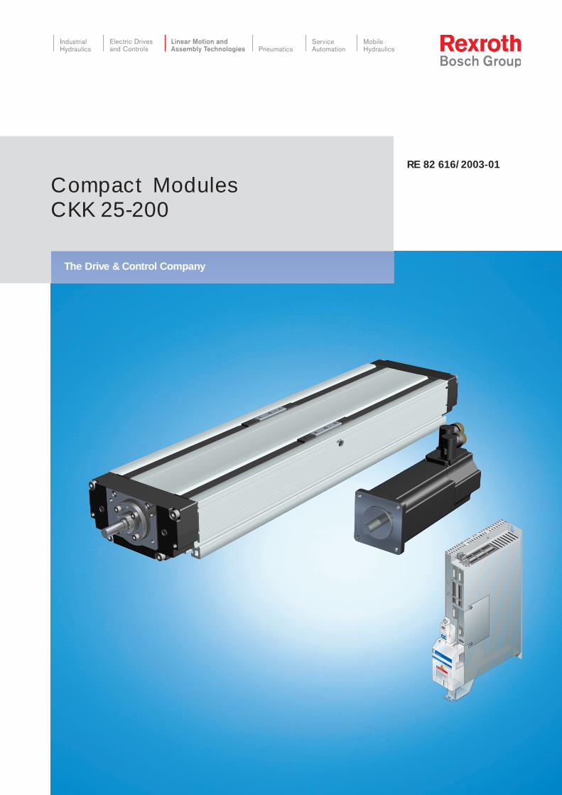
Compact Modules
CKK 25-200
RE 82 616/2003-01
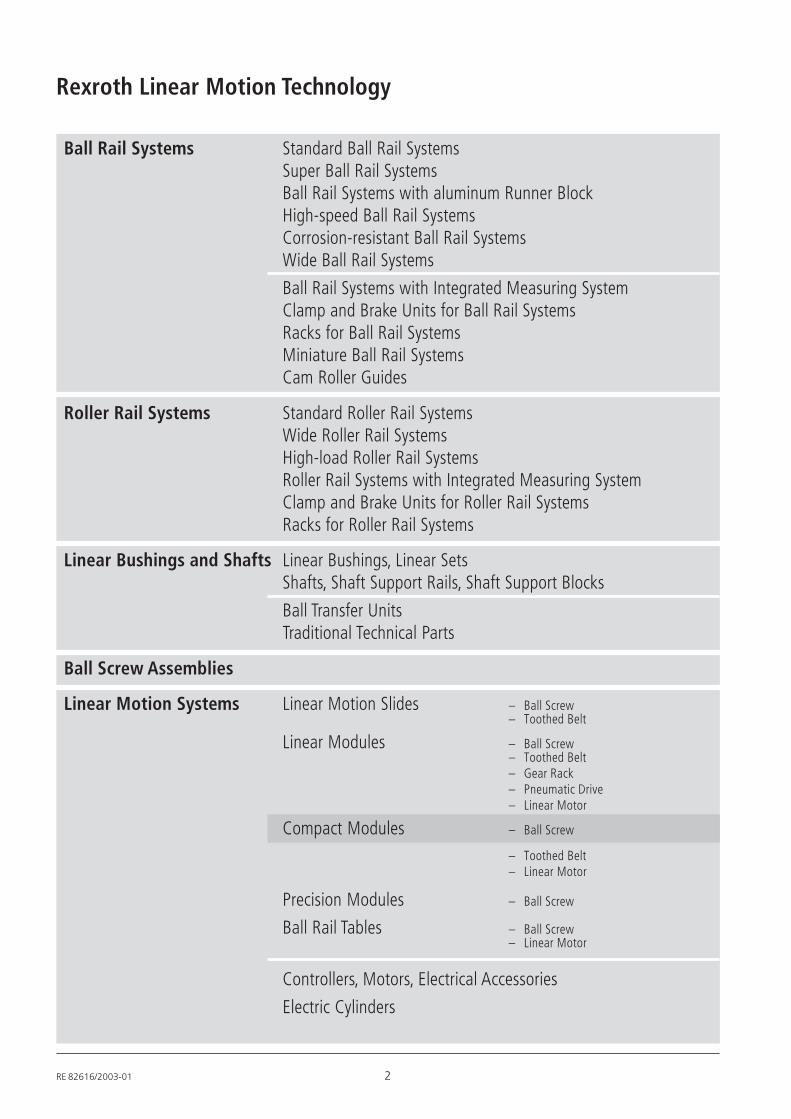
Ball Rail Systems Standard Ball Rail SystemsSuper Ball Rail SystemsBall Rail Systems with aluminum Runner BlockHigh-speed Ball Rail SystemsCorrosion-resistant Ball Rail SystemsWide Ball Rail Systems
Ball Rail Systems with Integrated Measuring SystemClamp and Brake Units for Ball Rail SystemsRacks for Ball Rail SystemsMiniature Ball Rail SystemsCam Roller Guides
Roller Rail Systems Standard Roller Rail SystemsWide Roller Rail SystemsHigh-load Roller Rail SystemsRoller Rail Systems with Integrated Measuring SystemClamp and Brake Units for Roller Rail SystemsRacks for Roller Rail Systems
Linear Bushings and Shafts Linear Bushings, Linear SetsShafts, Shaft Support Rails, Shaft Support Blocks
Ball Transfer UnitsTraditional Technical Parts
Ball Screw Assemblies
Linear Motion Systems Linear Motion Slides – Ball Screw– Toothed Belt
Linear Modules – Ball Screw– Toothed Belt– Gear Rack– Pneumatic Drive– Linear Motor
Compact Modules – Ball Screw
– Toothed Belt– Linear Motor
Precision Modules – Ball Screw
Ball Rail Tables – Ball Screw– Linear Motor
Controllers, Motors, Electrical Accessories
Electric Cylinders
Rexroth Linear Motion Technology
RE 82616/2003-01 2
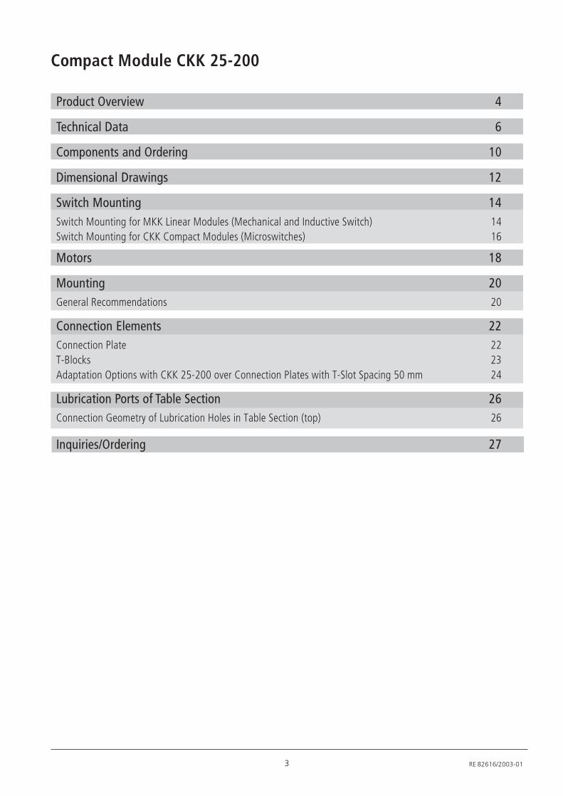
Compact Module CKK 25-200
3 RE 82616/2003-01
Product Overview 4
Technical Data 6
Components and Ordering 10
Dimensional Drawings 12
Switch Mounting 14Switch Mounting for MKK Linear Modules (Mechanical and Inductive Switch) 14Switch Mounting for CKK Compact Modules (Microswitches) 16
Motors 18
Mounting 20General Recommendations 20
Connection Elements 22Connection Plate 22T-Blocks 23Adaptation Options with CKK 25-200 over Connection Plates with T-Slot Spacing 50 mm 24
Lubrication Ports of Table Section 26Connection Geometry of Lubrication Holes in Table Section (top) 26
Inquiries/Ordering 27
4
Compact Modules CKK 25-200
RE 82616/2003-01
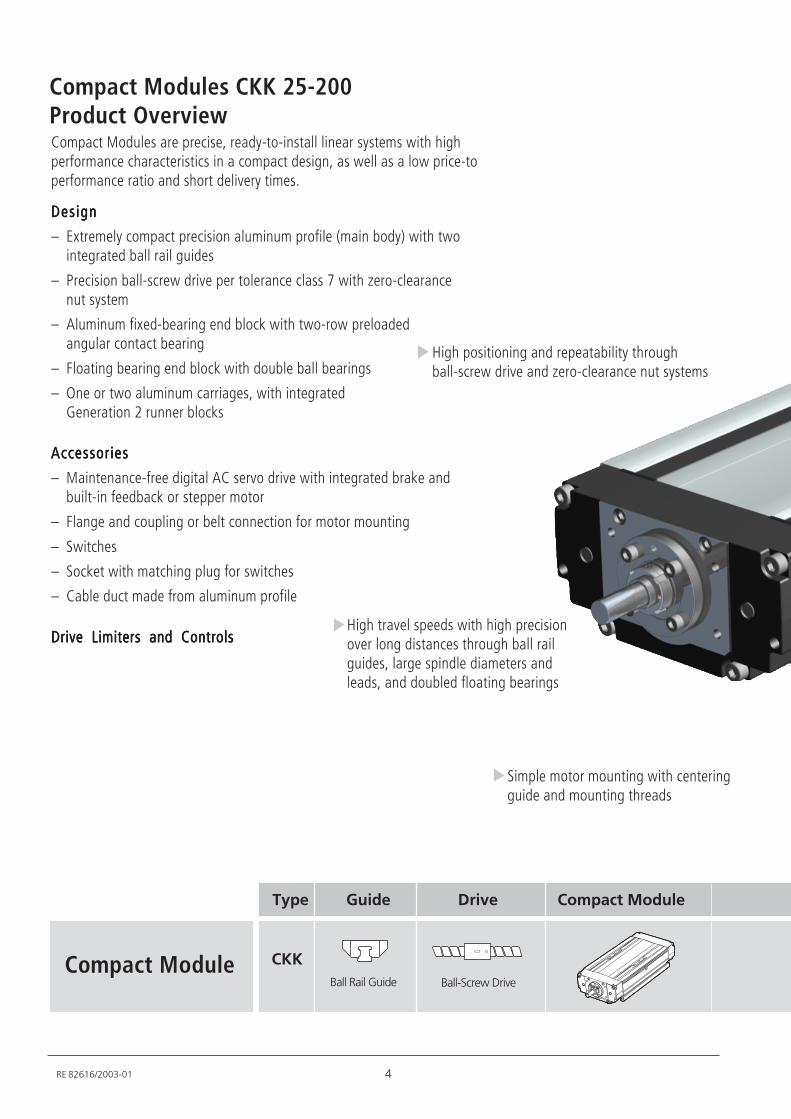
Type Guide Drive Compact Module
CKKCompact ModuleBall Rail Guide Ball-Screw Drive
DesignDesignDesignDesignDesign
– Extremely compact precision aluminum profile (main body) with twointegrated ball rail guides
– Precision ball-screw drive per tolerance class 7 with zero-clearancenut system
– Aluminum fixed-bearing end block with two-row preloadedangular contact bearing
– Floating bearing end block with double ball bearings
– One or two aluminum carriages, with integratedGeneration 2 runner blocks
AccessoriesAccessoriesAccessoriesAccessoriesAccessories
– Maintenance-free digital AC servo drive with integrated brake andbuilt-in feedback or stepper motor
– Flange and coupling or belt connection for motor mounting
– Switches
– Socket with matching plug for switches
– Cable duct made from aluminum profile
Drive Limiters and ControlsDrive Limiters and ControlsDrive Limiters and ControlsDrive Limiters and ControlsDrive Limiters and Controls
Compact Modules are precise, ready-to-install linear systems with highperformance characteristics in a compact design, as well as a low price-toperformance ratio and short delivery times.
Product Overview
High positioning and repeatability throughball-screw drive and zero-clearance nut systems
High travel speeds with high precisionover long distances through ball railguides, large spindle diameters andleads, and doubled floating bearings
Simple motor mounting with centeringguide and mounting threads
5 RE 82616/2003-01
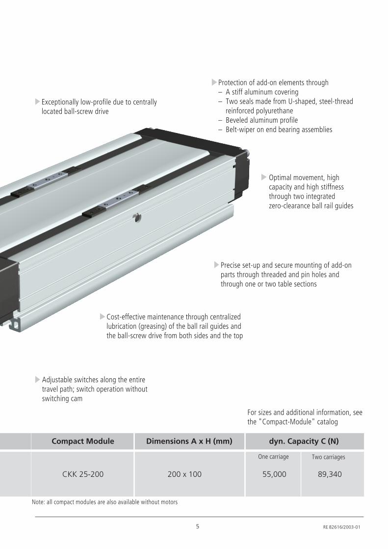
CKK 25-200 200 x 100 55,000 89,340
Compact Module Dimensions A x H (mm) dyn. Capacity C (N)
One carriage Two carriages
For sizes and additional information, seethe "Compact-Module" catalog
Adjustable switches along the entiretravel path; switch operation withoutswitching cam
Cost-effective maintenance through centralizedlubrication (greasing) of the ball rail guides andthe ball-screw drive from both sides and the top
Note: all compact modules are also available without motors
Exceptionally low-profile due to centrallylocated ball-screw drive
Precise set-up and secure mounting of add-onparts through threaded and pin holes andthrough one or two table sections
Optimal movement, highcapacity and high stiffnessthrough two integratedzero-clearance ball rail guides
Protection of add-on elements through– A stiff aluminum covering– Two seals made from U-shaped, steel-thread
reinforced polyurethane– Beveled aluminum profile– Belt-wiper on end bearing assemblies
6
Compact Modules CKK 25-200
RE 82616/2003-01
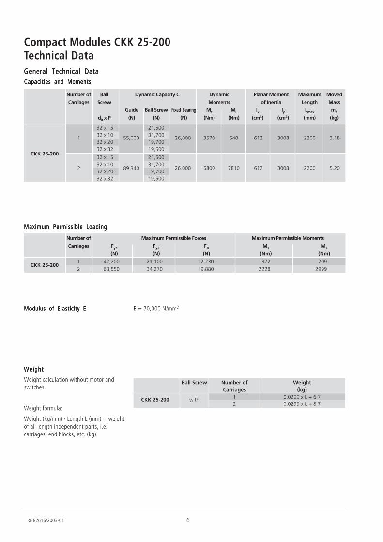
E = 70,000 N/mm2Modulus of Elasticity EModulus of Elasticity EModulus of Elasticity EModulus of Elasticity EModulus of Elasticity E
WeightWeightWeightWeightWeight
Weight calculation without motor andswitches.
Weight formula:
Weight (kg/mm) · Length L (mm) + weightof all length independent parts, i.e.carriages, end blocks, etc. (kg)
Ball Screw Number of Weight
Carriages (kg)
CKK 25-200 with1 0.0299 x L + 6.7
2 0.0299 x L + 8.7
Technical DataGeneral Technical DataGeneral Technical DataGeneral Technical DataGeneral Technical DataGeneral Technical DataCapacities and MomentsCapacities and MomentsCapacities and MomentsCapacities and MomentsCapacities and Moments
Number of Maximum Permissible Forces Maximum Permissible Moments
Carriages Fy1 Fy2 FX Mt ML
(N) (N) (N) (Nm) (Nm)
1 42,200 21,100 12,230 1372 209
2 68,550 34,270 19,880 2228 2999
Maximum Permissible LoadingMaximum Permissible LoadingMaximum Permissible LoadingMaximum Permissible LoadingMaximum Permissible Loading
Number of Ball Dynamic Capacity C Dynamic Planar Moment Maximum Moved
Carriages Screw Moments of Inertia Length Mass
Guide Ball Screw Fixed Bearing Mt ML Ix Iy Lmax mb
d0 x P (N) (N) (N) (Nm) (Nm) (cm4) (cm4) (mm) (kg)
CKK 25-200
CKK 25-200
1
2
32 x 5
32 x 10
32 x 20
32 x 32
32 x 5
32 x 10
32 x 20
32 x 32
55,000
89,340
21,500
31,700
19,700
19,500
21,500
31,700
19,700
19,500
26,000 3570 540 612 3008 2200 3.18
26,000 5800 7810 612 3008 2200 5.20
7 RE 82616/2003-01
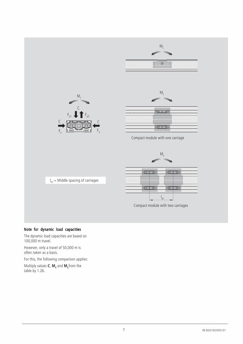
Note for dynamic load capacitiesNote for dynamic load capacitiesNote for dynamic load capacitiesNote for dynamic load capacitiesNote for dynamic load capacities
The dynamic load capacities are based on100,000 m travel.
However, only a travel of 50,000 m isoften taken as a basis.
For this, the following comparison applies:
Multiply values C, Mt and MLfrom thetable by 1.26.
ML
ML
C
Mt
Fy2
FxFx
Fy1
ML
Compact module with one carriage
Compact module with two carriages
lm
lm = Middle spacing of carriages
CC
8
Compact Modules CKK 25-200
RE 82616/2003-01
Technical Data
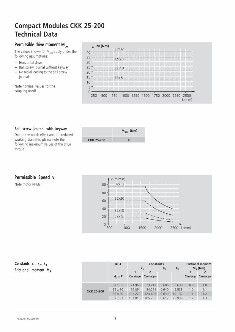
Constants kConstants kConstants kConstants kConstants k11111, k, k, k, k, k22222, k, k, k, k, k33333
Frictional moment MFrictional moment MFrictional moment MFrictional moment MFrictional moment MRRRRR
KGT Constants Frictional moment
k1 k2 k3 MR (Nm)1 2 1 2
d0 x P Carriage Carriages Carriage Carriages
32 x 5 71.968 73.247 0.605 0.633 0.9 1.0
32 x 10 79.094 84.211 0.640 2.533 1.0 1.1
32 x 20 103.229 123.695 0.639 10.132 1.1 1.2
32 x 32 152.810 205.205 0.617 25.938 1.2 1.3
CKK 25-200
Permissible Speed vPermissible Speed vPermissible Speed vPermissible Speed vPermissible Speed vNote motor RPMs!
*+
,+
-+
.+
/++
+%01/+++ /++ -+++ -++++
2-3/+
04 12-32-
2-3-+
2-3
Ball screw journal with keywayBall screw journal with keywayBall screw journal with keywayBall screw journal with keywayBall screw journal with keyway
Due to the notch effect and the reducedworking diameter, please note thefollowing maximum values of the drivetorque!
Mper (Nm)
CKK 25-200 18
Permissible drive moment MPermissible drive moment MPermissible drive moment MPermissible drive moment MPermissible drive moment Mperperperperper
The values shown for Mper apply under thefollowing assumptions:
– Horizontal drive– Ball screw journal without keyway– No radial loading to the ball screw
journal
Note nominal values for thecoupling used!
++ 5+ /+++ /-+ /++ /5+
/+
-+
2+
-+
/
-
2*+
+--+-+++ -++
2-3-+
2-32-
2-3/+
2-3
%01
9 RE 82616/2003-01
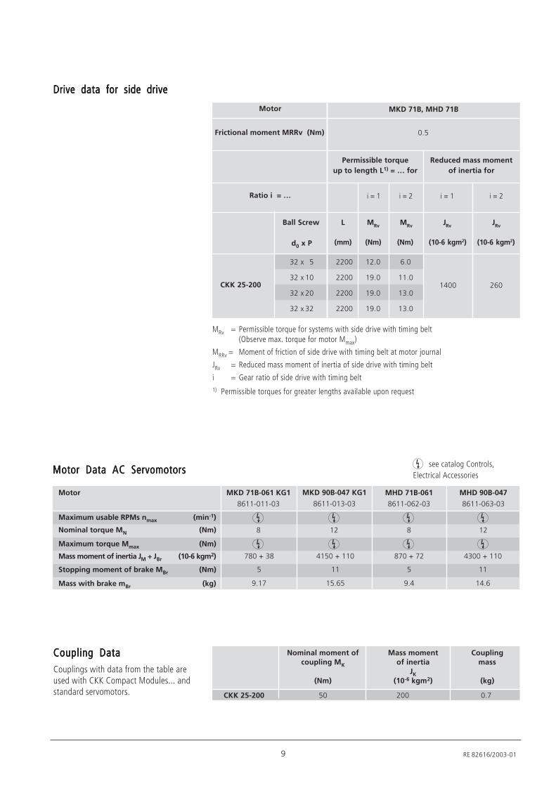
Motor Data AC ServomotorsMotor Data AC ServomotorsMotor Data AC ServomotorsMotor Data AC ServomotorsMotor Data AC Servomotors
Motor
Maximum usable RPMs nmax (min-1)
Nominal torque MN (Nm)
Maximum torque Mmax (Nm)
Mass moment of inertia JM + JBr (10-6 kgm2)
Stopping moment of brake MBr (Nm)
Mass with brake mBr (kg)
MKD 71B-061 KG1
8611-011-03
780 + 38
5
9.17
8
see catalog Controls,Electrical Accessories
MKD 90B-047 KG1
8611-013-03
MHD 71B-061
8611-062-03
870 + 72
5
9.4
8
Coupling DataCoupling DataCoupling DataCoupling DataCoupling DataCouplings with data from the table areused with CKK Compact Modules... andstandard servomotors.
Nominal moment of Mass moment Couplingcoupling MK of inertia mass
JK
(Nm) (10-6 kgm2) (kg)
CKK 25-200 50 200 0.7
MRv = Permissible torque for systems with side drive with timing belt(Observe max. torque for motor Mmax)
MRRv = Moment of friction of side drive with timing belt at motor journal
JRv = Reduced mass moment of inertia of side drive with timing belt
i = Gear ratio of side drive with timing belt1) Permissible torques for greater lengths available upon request
0.5
Permissible torque
up to length L1) = … for
Reduced mass moment
of inertia for
(10-6 kgm2)(10-6 kgm2)
i = 2i = 1i = 2i = 1
(Nm)(Nm)(mm)
MRv
L MRv
JRv
JRv
Ball Screw
Motor
Frictional moment MRRv (Nm)
Ratio i = …
32 x 5
32 x 10
32 x 20
32 x 32
CKK 25-200
2200
2200
2200
2200
12.0
19.0
19.0
19.0
6.0
11.0
13.0
13.0
d0 x P
Drive data for side driveDrive data for side driveDrive data for side driveDrive data for side driveDrive data for side drive
1400 260
MKD 71B, MHD 71B
MHD 90B-047
8611-063-03
4150 + 110
11
15.65
12
4300 + 110
11
14.6
12
10
Compact Modules CKK 25-200
RE 82616/2003-01
01
01
MF01
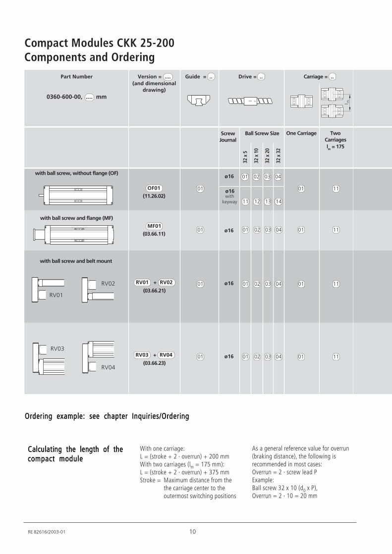
Components and Ordering
32 x
5
32 x
10
32 x
20
32 x
32
ø16
Part Number
0360-600-00, .... mm
Drive = ..
ScrewJournal
Ball Screw Size One Carriage
Carriage = ..Version = ....
(and dimensionaldrawing)
TwoCarriages
lm = 175
RV01
RV02
RV03
RV04
01 11
With one carriage:L = (stroke + 2 · overrun) + 200 mmWith two carriages (lm = 175 mm):L = (stroke + 2 · overrun) + 375 mmStroke = Maximum distance from the
the carriage center to theoutermost switching positions
As a general reference value for overrun(braking distance), the following isrecommended in most cases:Overrun = 2 · screw lead PExample:Ball screw 32 x 10 (d0 x P),Overrun = 2 · 10 = 20 mm
Calculating the length of theCalculating the length of theCalculating the length of theCalculating the length of theCalculating the length of thecompact modulecompact modulecompact modulecompact modulecompact module
01 02 03 04
01 02 03 04
with ball screw and flange (MF)
with ball screw and belt mount
(03.66.11)
(03.66.21)
01OF01ø16 01 11
11 12 13 14
with ball screw, without flange (OF)
(11.26.02) withkeyway
01 11
01 01 02 03 04(03.66.23)
01 11
RV01 + RV02
RV03 + RV04
Guide = ..
ø16 01 02 03 04
Ordering example: see chapter Inquiries/OrderingOrdering example: see chapter Inquiries/OrderingOrdering example: see chapter Inquiries/OrderingOrdering example: see chapter Inquiries/OrderingOrdering example: see chapter Inquiries/Ordering
ø16
ø16
11 RE 82616/2003-01
22
21
i = 2
i = 1
01
01
MKD 71B-061 11
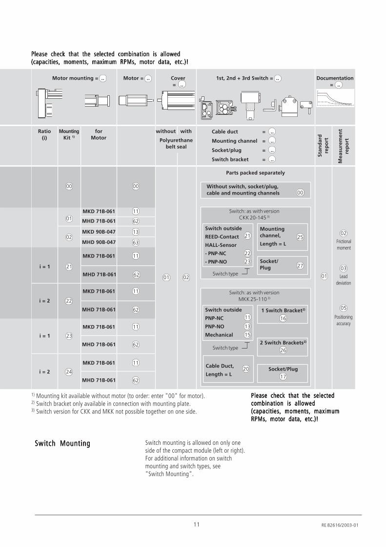
Please check that the selected combination is allowedPlease check that the selected combination is allowedPlease check that the selected combination is allowedPlease check that the selected combination is allowedPlease check that the selected combination is allowed(capacities, moments, maximum RPMs, motor data, etc.)!(capacities, moments, maximum RPMs, motor data, etc.)!(capacities, moments, maximum RPMs, motor data, etc.)!(capacities, moments, maximum RPMs, motor data, etc.)!(capacities, moments, maximum RPMs, motor data, etc.)!
Motor mounting = .. Motor = .. Cover
= ..
Documentation
= ..
1st, 2nd + 3rd Switch = ..
Ratio
(i)
MountingKit 1)
forMotor
without with
Polyurethanebelt seal
Sta
nd
ard
rep
ort
Me
asu
rem
en
tre
po
rt
02
Switch MountingSwitch MountingSwitch MountingSwitch MountingSwitch Mounting Switch mounting is allowed on only oneside of the compact module (left or right).For additional information on switchmounting and switch types, see"Switch Mounting".
00 00
02
MHD 71B-061
MKD 90B-047
MHD 90B-047
MKD 71B-061
MHD 71B-061
MKD 71B-061
MHD 71B-061
24
23
i = 2
i = 1
MKD 71B-061
MHD 71B-061
MKD 71B-061
MHD 71B-061
Cable duct = ..
Mounting channel = ..
Socket/plug = ..
Switch bracket = ..
Parts packed separately
01
Frictionalmoment
Positioningaccuracy
02
Leaddeviation
03
05Switch outside
PNP-NC
PNP-NO
Mechanical
Switch: as with version
MKK 25-110 3)
11
1 Switch Bracket2)
16
2 Switch Brackets2)
26
Socket/Plug
17
Switch type
Cable Duct,
Length = L20
Switch outside
REED-Contact
HALL-Sensor
- PNP-NC
- PNP-NO
Switch: as with versionCKK 20-145 3)
21
Mounting
channel,
Length = L
25
Socket/Plug 27
Switch type
Without switch, socket/plug,
cable and mounting channels 00
15
13
62
13
63
62
11
62
11
62
11
62
11
1) Mounting kit available without motor (to order: enter "00" for motor).2) Switch bracket only available in connection with mounting plate.3) Switch version for CKK and MKK not possible together on one side.
22
23
Please check that the selectedPlease check that the selectedPlease check that the selectedPlease check that the selectedPlease check that the selectedcombination is allowedcombination is allowedcombination is allowedcombination is allowedcombination is allowed(capacities, moments, maximum(capacities, moments, maximum(capacities, moments, maximum(capacities, moments, maximum(capacities, moments, maximumRPMs, motor data, etc.)!RPMs, motor data, etc.)!RPMs, motor data, etc.)!RPMs, motor data, etc.)!RPMs, motor data, etc.)!
12
Compact Modules CKK 25-200
RE 82616/2003-01
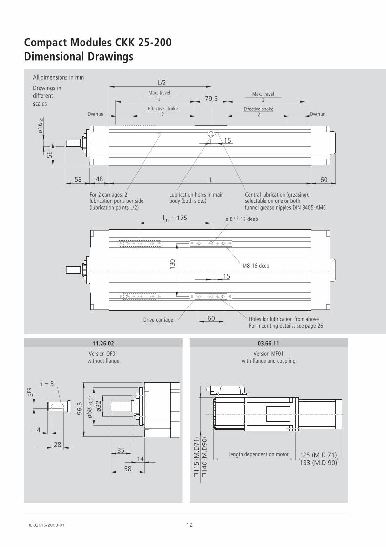
Dimensional Drawings
%
%4-
567
.+*,,
8/.
5
.
.+
9/5
/
/
/2+
/-0:5/1/220:6+1
//0:5/1
/*+0:6+1
All dimensions in mm
Drawings indifferentscales
Drive carriage
ø 8 H7-12 deep
03.66.11
Version MF01with flange and coupling
length dependent on motor
Max. travel2
Holes for lubrication from aboveFor mounting details, see page 26
11.26.02
Version OF01without flange
-,
92
2;6
*
2
82-
8.,!+7+/
/*
6.7
,
Overrun OverrunEffective stroke
2
Max. travel2
Effective stroke2
Lubrication holes in mainbody (both sides)
Central lubrication (greasing):selectable on one or bothfunnel grease nipples DIN 3405-AM6
For 2 carriages: 2lubrication ports per side(lubrication points L/2)
M8-16 deep
13 RE 82616/2003-01
*7,
/7,
27-
27-
/72,7-
7-
-7
*7,
/*7
/-//7/
.7-
,
-+72
/+7-/-75
.
/.
6,7
/++
-
-++
//-
*.
6+
,7
6.7
..
6/.-
/.09/1
09-1
2++
//.
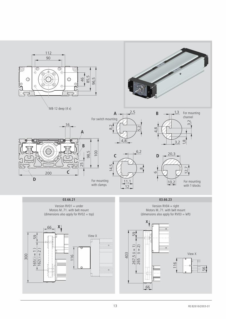
M8-12 deep (4 x)For mountingchannelFor switch mounting
03.66.21
Version RV01 = underMotors M..71. with belt mount
(dimensions also apply for RV02 = top)
View X
For mountingwith clamps
For mountingwith T-blocks
03.66.23
Version RV04 = rightMotors M..71. with belt mount
(dimensions also apply for RV03 = left)
//.
*+2
-.5709/1
-.09-1
6
.
..
View X
14
Compact Modules CKK 25-200
RE 82616/2003-01
-+
-
*+
.+
.
67
5 /27
/-</
+
+
Switch Mounting
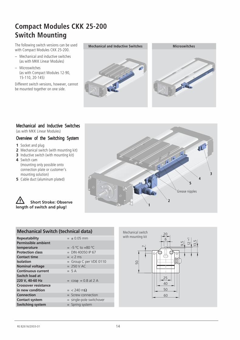
Repeatability = ± 0.05 mm
Permissible ambient
temperature = -5 ºC to +80 ºC
Protection class = DIN 40050 IP 67
Contact time = < 2 ms
Isolation = Group C per VDE 0110
Nominal voltage = 250 V AC
Continuous current = 5 A
Switch load at
220 V, 40-60 Hz = cosϕ = 0.8 at 2 A
Crossover resistance
in new condition = < 240 mΩConnection = Screw connection
Contact system = single-pole switchover
Switching system = Spring system
Mechanical Switch (technical data)
Mechanical and Inductive SwitchesMechanical and Inductive SwitchesMechanical and Inductive SwitchesMechanical and Inductive SwitchesMechanical and Inductive Switches(as with MKK Linear Modules)
Overview of the Switching SystemOverview of the Switching SystemOverview of the Switching SystemOverview of the Switching SystemOverview of the Switching System1 Socket and plug2 Mechanical switch (with mounting kit)3 Inductive switch (with mounting kit)4 Switch cam
(mounting only possible ontoconnection plate or customer‘smounting solution)
5 Cable duct (aluminum plated)
Mechanical switchwith mounting kit
1111122222
33333
5555544444
Short Stroke: Observelength of switch and plug!
Grease nipples
The following switch versions can be usedwith Compact Modules CKK 25-200.
– Mechanical and inductive switches(as with MKK Linear Modules)
– Microswitches(as with Compact Modules 12-90,15-110, 20-145)
Different switch versions, however, cannotbe mounted together on one side.
Mechanical and Inductive Switches Microswitches
15 RE 82616/2003-01
2+
2
*
5
--
/5/6 /+
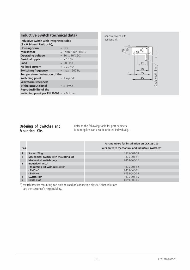
Inductive switch with integrated cable
(3 x 0.14 mm2 Unitronic),
Housing form = NO
Minisensor = Form A DIN 41635
Operating voltage = 10 ... 30 V DC
Residual ripple = ≤ 10 %
Load = 200 mA
No-load current = ≤ 20 mA
Switching frequency = max. 1500 Hz
Temperature fluctuation of the
switching point = ≤ 4 µm/K
Waveform steepness
of the output signal = ≥ 1V/µs
Reproducibility of the
switching point per EN 50008 = ≤ 0.1 mm
Inductive Switch (technical data)
Cabl
e le
ngth
: 3 m
Inductive switch withmounting kit
*) Switch bracket mounting can only be used on connection plates. Other solutionsare the customer‘s responsibility.
Part numbers for installation on CKK 25-200
Pos. Version with mechanical and inductive switches*
1 Socket/Plug 1175-001-53
2 Mechanical switch with mounting kit 1175-001-51
Mechanical switch only 8453-040-16
3 Inductive switch
- Mounting kit without switch 1175-001-52
- PNP NC 8453-040-01
- PNP No 8453-040-03
4 Switch cam 1175-001-505 Cable duct 0399-800-06
Ordering of Switches andOrdering of Switches andOrdering of Switches andOrdering of Switches andOrdering of Switches andMounting KitsMounting KitsMounting KitsMounting KitsMounting Kits
Refer to the following table for part numbers.Mounting kits can also be ordered individually.
16
Compact Modules CKK 25-200
RE 82616/2003-01
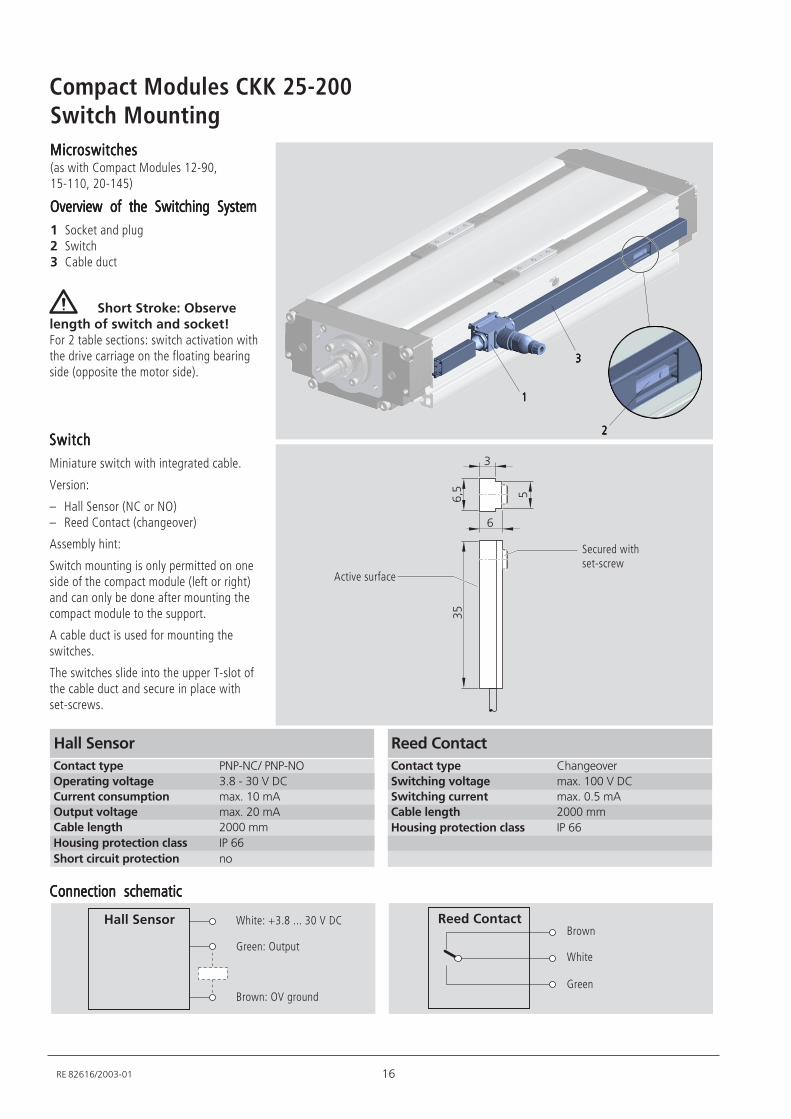
Switch Mounting
Contact type PNP-NC/ PNP-NO
Operating voltage 3.8 - 30 V DC
Current consumption max. 10 mA
Output voltage max. 20 mA
Cable length 2000 mm
Housing protection class IP 66
Short circuit protection no
Hall Sensor
MicroswitchesMicroswitchesMicroswitchesMicroswitchesMicroswitches(as with Compact Modules 12-90,15-110, 20-145)
Overview of the Switching SystemOverview of the Switching SystemOverview of the Switching SystemOverview of the Switching SystemOverview of the Switching System1 Socket and plug2 Switch3 Cable duct
Short Stroke: Observelength of switch and socket!For 2 table sections: switch activation withthe drive carriage on the floating bearingside (opposite the motor side).
SwitchSwitchSwitchSwitchSwitchMiniature switch with integrated cable.
Version:
– Hall Sensor (NC or NO)– Reed Contact (changeover)
Assembly hint:
Switch mounting is only permitted on oneside of the compact module (left or right)and can only be done after mounting thecompact module to the support.
A cable duct is used for mounting theswitches.
The switches slide into the upper T-slot ofthe cable duct and secure in place withset-screws.
Contact type Changeover
Switching voltage max. 100 V DC
Switching current max. 0.5 mA
Cable length 2000 mm
Housing protection class IP 66
Reed Contact
Connection schematicConnection schematicConnection schematicConnection schematicConnection schematic
Brown
.
.7
2
2
Active surface
Secured withset-screw
White
Green
White: +3.8 ... 30 V DC
Green: Output
Brown: OV ground
Hall Sensor Reed Contact
11111
22222
33333
17 RE 82616/2003-01
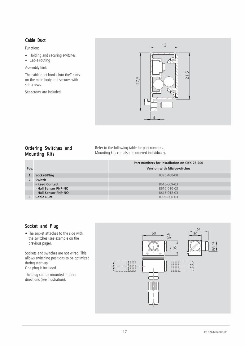
Socket and PlugSocket and PlugSocket and PlugSocket and PlugSocket and Plug• The socket attaches to the side with
the switches (see example on theprevious page).
Sockets and switches are not wired. Thisallows switching positions to be optimizedduring start-up.One plug is included.
The plug can be mounted in threedirections (see illustration).
+ 2+
2
/-7.
;"/.
/
Part numbers for installation on CKK 25-200
Pos. Version with Microswitches
1 Socket/Plug 0375-400-00
2 Switch
- Reed Contact 8616-009-03
- Hall Sensor PNP-NC 8616-010-03
- Hall-Sensor PNP-NO 8616-012-03
3 Cable Duct 0399-800-63
Ordering Switches andOrdering Switches andOrdering Switches andOrdering Switches andOrdering Switches andMounting KitsMounting KitsMounting KitsMounting KitsMounting Kits
Cable DuctCable DuctCable DuctCable DuctCable Duct
Function:
– Holding and securing switches– Cable routing
Assembly hint:
The cable duct hooks into theT-slotson the main body and secures withset-screws.
Set-screws are included.
Refer to the following table for part numbers.Mounting kits can also be ordered individually.
-57 -/
7
/2
2
18
Compact Modules CKK 25-200
RE 82616/2003-01
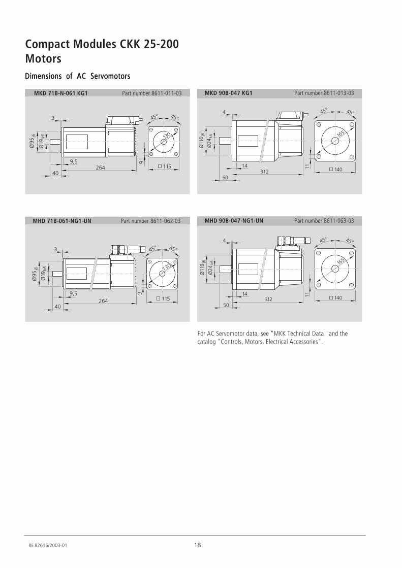
MotorsDimensions of AC ServomotorsDimensions of AC ServomotorsDimensions of AC ServomotorsDimensions of AC ServomotorsDimensions of AC Servomotors
MKD 90B-047 KG1 Part number 8611-013-03MKD 71B-N-061 KG1 Part number 8611-011-03
67
*+
2
=6
>.
=/6
.
-.*
*? *?
//
6/2+
MHD 71B-061-NG1-UN Part number 8611-062-03
67
*? *?
*+
2
=6
>.
=/6
.
//
6
/2+
-.*
For AC Servomotor data, see "MKK Technical Data" and thecatalog "Controls, Motors, Electrical Accessories".
MHD 90B-047-NG1-UN Part number 8611-063-03
=//+>.
*
2/-/*
=-*
.
/*+//
/.
+
*? *?
=//+>.
*
2/-/*
=-*
.
/*+//
/.
+
*? *?
19 RE 82616/2003-01
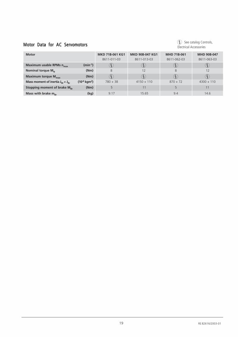
Motor Data for AC ServomotorsMotor Data for AC ServomotorsMotor Data for AC ServomotorsMotor Data for AC ServomotorsMotor Data for AC Servomotors
Motor
Maximum usable RPMs nmax (min-1)
Nominal torque MN (Nm)
Maximum torque Mmax (Nm)
Mass moment of inertia JM + JBr (10-6 kgm2)
Stopping moment of brake MBr (Nm)
Mass with brake mBr (kg)
MKD 71B-061 KG1
8611-011-03
780 + 38
5
9.17
8
See catalog Controls,Electrical Accessories
MKD 90B-047 KG1
8611-013-03
MHD 71B-061
8611-062-03
870 + 72
5
9.4
8
MHD 90B-047
8611-063-03
4150 + 110
11
15.65
12
4300 + 110
11
14.6
12
20
Compact Modules CKK 25-200
RE 82616/2003-01
//
" 38,
3/.
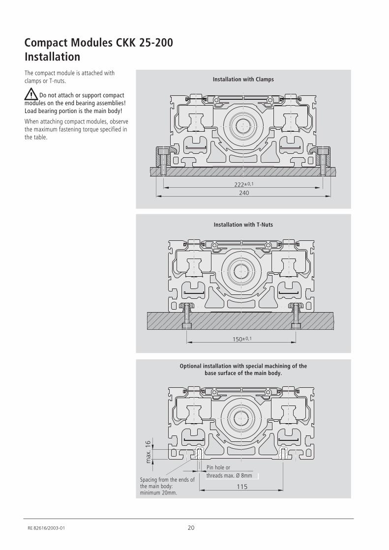
InstallationThe compact module is attached withclamps or T-nuts.
Do not attach or support compactmodules on the end bearing assemblies!Load bearing portion is the main body!
When attaching compact modules, observethe maximum fastening torque specified inthe table.
Installation with Clamps
Installation with T-Nuts
Optional installation with special machining of thebase surface of the main body.
Spacing from the ends ofthe main body:minimum 20mm.
/+@+7/
-*+---@+7/
Pin hole orthreads max. Ø 8mm
21 RE 82616/2003-01
6
/6-6
+ ,,/
-57
6
/6-6
5+ /+,
/.7
-57
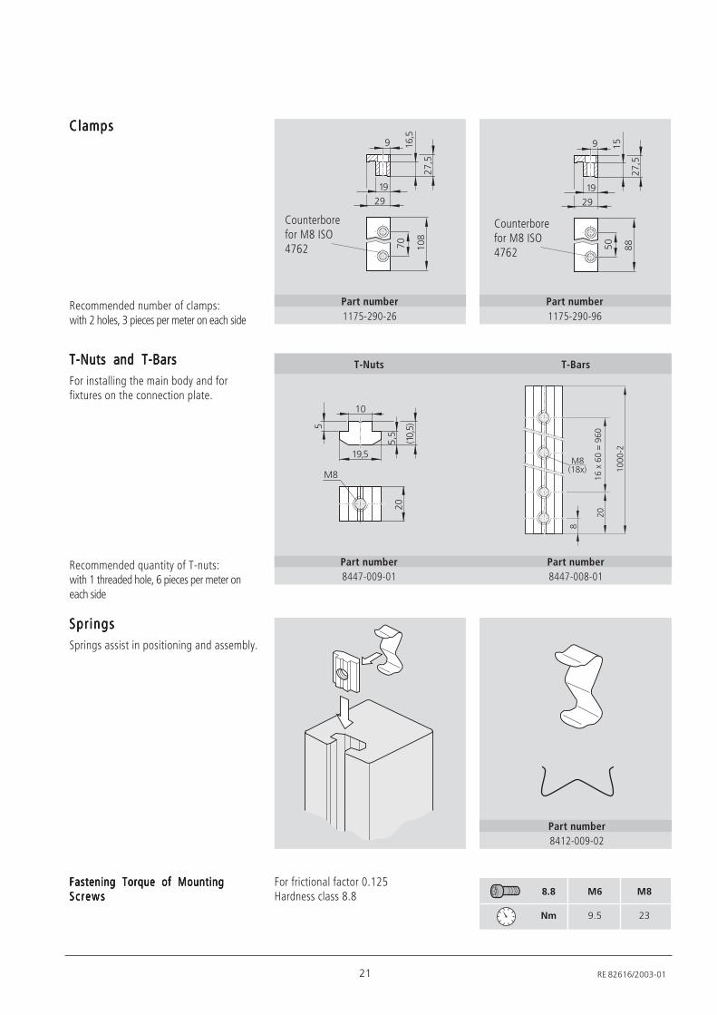
Recommended number of clamps:with 2 holes, 3 pieces per meter on each side
Fastening Torque of MountingFastening Torque of MountingFastening Torque of MountingFastening Torque of MountingFastening Torque of MountingScrewsScrewsScrewsScrewsScrews 8.8 M6 M8
Nm 9.5 23
Part number1175-290-26
Counterborefor M8 ISO4762
For frictional factor 0.125Hardness class 8.8
Part number8447-009-01
T-Nuts
Recommended quantity of T-nuts:with 1 threaded hole, 6 pieces per meter oneach side
Part number8447-008-01
T-BarsT-Nuts and T-BarsT-Nuts and T-BarsT-Nuts and T-BarsT-Nuts and T-BarsT-Nuts and T-BarsFor installing the main body and forfixtures on the connection plate.
ClampsClampsClampsClampsClamps
Part number8412-009-02
SpringsSpringsSpringsSpringsSpringsSprings assist in positioning and assembly.
Part number1175-290-96
Counterborefor M8 ISO4762
/+++!-
,
-+
:,0/,31
/.3.+96.+
/67
/+0/+71
7
-+
:,
22
Compact Modules CKK 25-200
RE 82616/2003-01
-+72
/6+
/6,
22
-
++
+
/2+
//+
7
/+7-
/2+
//
//+
/-7- *2/.+
/+72
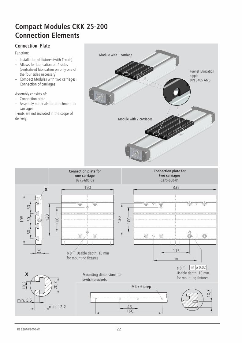
Connection ElementsConnection PlateConnection PlateConnection PlateConnection PlateConnection PlateFunction:
– Installation of fixtures (with T-nuts)– Allows for lubrication on 4 sides
(centralized lubrication on only one ofthe four sides necessary)
– Compact Modules with two carriages:Connection of carriages
Assembly consists of:– Connection plate– Assembly materials for attachment to
carriagesT-nuts are not included in the scope ofdelivery.
ø 0,02
ø 8H7, Usable depth: 10 mmfor mounting fixtures
Connection plate forone carriage
Connection plate fortwo carriages
ø 8H7, ,Usable depth: 10 mmfor mounting fixtures
0375-600-02 0375-600-01
Funnel lubricationnippleDIN 3405 AM6
Module with 1 carriage
Module with 2 carriages
Mounting dimensions forswitch brackets
M4 x 6 deep
10
0
10
0
23 RE 82616/2003-01
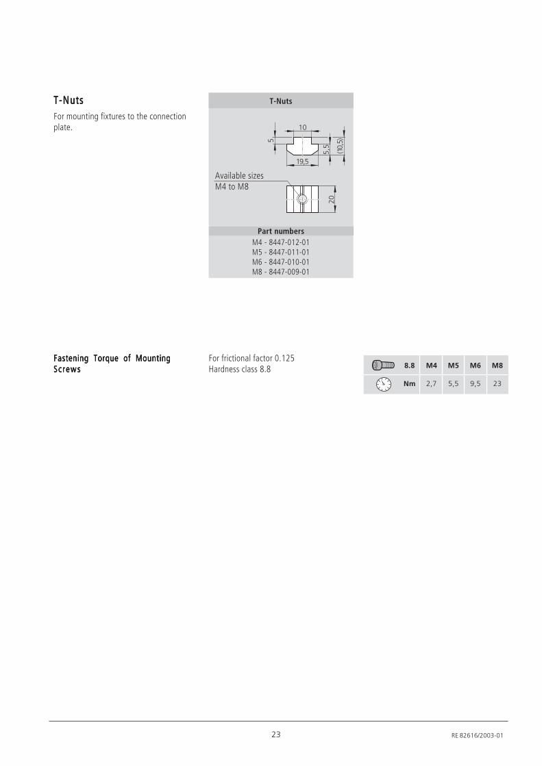
T-NutsT-NutsT-NutsT-NutsT-NutsFor mounting fixtures to the connectionplate.
Part numbersM4 - 8447-012-01M5 - 8447-011-01M6 - 8447-010-01M8 - 8447-009-01
T-Nuts
Fastening Torque of MountingFastening Torque of MountingFastening Torque of MountingFastening Torque of MountingFastening Torque of MountingScrewsScrewsScrewsScrewsScrews 8.8 M4 M5 M6 M8
Nm 2,7 5,5 9,5 23
For frictional factor 0.125Hardness class 8.8
/67
/+
0/+71
7
-+
Available sizesM4 to M8
24
Compact Modules CKK 25-200
RE 82616/2003-01
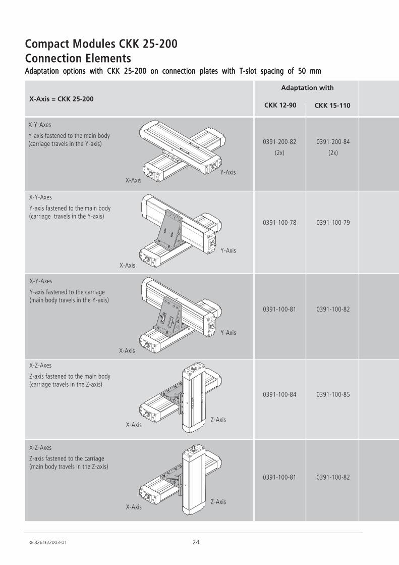
Connection ElementsAdaptation options with CKK 25-200 on connection plates with T-slot spacing of 50 mmAdaptation options with CKK 25-200 on connection plates with T-slot spacing of 50 mmAdaptation options with CKK 25-200 on connection plates with T-slot spacing of 50 mmAdaptation options with CKK 25-200 on connection plates with T-slot spacing of 50 mmAdaptation options with CKK 25-200 on connection plates with T-slot spacing of 50 mm
X-Axis = CKK 25-200
Adaptation with
X-Y-Axes
Y-axis fastened to the main body(carriage travels in the Y-axis)
X-Y-Axes
Y-axis fastened to the main body(carriage travels in the Y-axis)
X-Axis
Y-Axis
X-Y-Axes
Y-axis fastened to the carriage(main body travels in the Y-axis)
X-Axis
Y-Axis
X-Z-Axes
Z-axis fastened to the main body(carriage travels in the Z-axis)
X-AxisZ-Axis
X-Z-Axes
Z-axis fastened to the carriage(main body travels in the Z-axis)
X-AxisZ-Axis
CKK 12-90 CKK 15-110
0391-200-82
(2x)
0391-200-84
(2x)
X-AxisY-Axis
0391-100-78 0391-100-79
0391-100-81 0391-100-82
0391-100-84 0391-100-85
0391-100-81 0391-100-82
25 RE 82616/2003-01
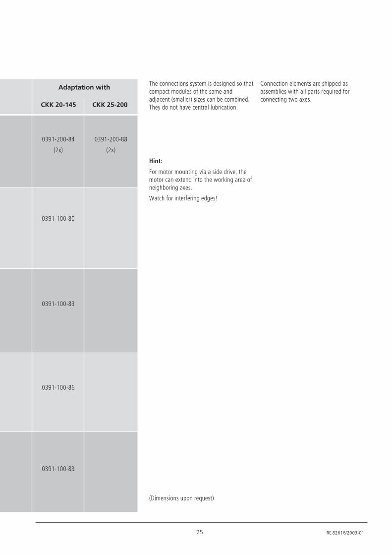
CKK 20-145 CKK 25-200
0391-200-84
(2x)
0391-200-88
(2x)
0391-100-80
0391-100-83
0391-100-86
0391-100-83
The connections system is designed so thatcompact modules of the same andadjacent (smaller) sizes can be combined.They do not have central lubrication.
Connection elements are shipped asassemblies with all parts required forconnecting two axes.
Adaptation with
Hint:
For motor mounting via a side drive, themotor can extend into the working area ofneighboring axes.
Watch for interfering edges!
(Dimensions upon request)
26
Compact Modules CKK 25-200
RE 82616/2003-01
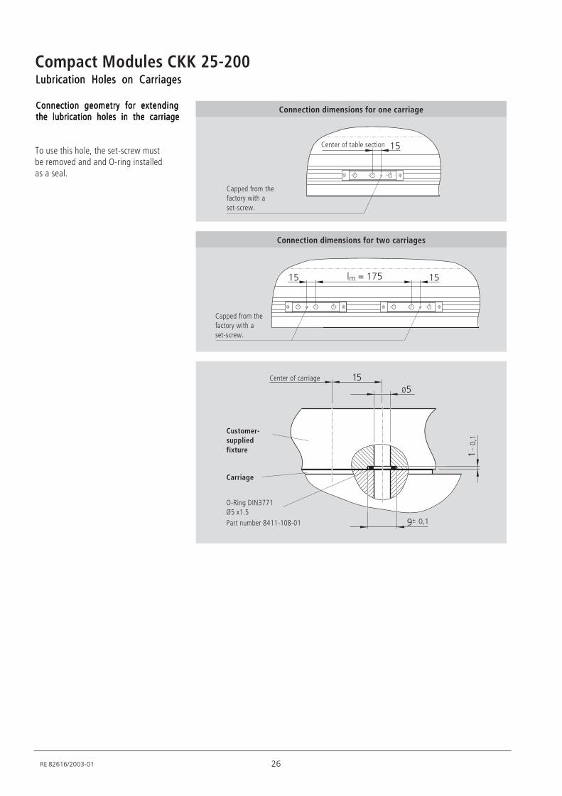
Lubrication Holes on CarriagesLubrication Holes on CarriagesLubrication Holes on CarriagesLubrication Holes on CarriagesLubrication Holes on Carriages
Connection geometry for extendingConnection geometry for extendingConnection geometry for extendingConnection geometry for extendingConnection geometry for extendingthe lubrication holes in the carriagethe lubrication holes in the carriagethe lubrication holes in the carriagethe lubrication holes in the carriagethe lubrication holes in the carriage
To use this hole, the set-screw mustbe removed and and O-ring installedas a seal.
/2
/
Capped from thefactory with aset-screw.
Center of table section
Connection dimensions for one carriage
Connection dimensions for two carriages
// 9/5
Capped from thefactory with aset-screw.
+7/
A
/
/
+7/6<A
O-Ring DIN3771Ø5 x1.5Part number 8411-108-01
Carriage
Customer-suppliedfixture
Center of carriage
27 RE 82616/2003-01
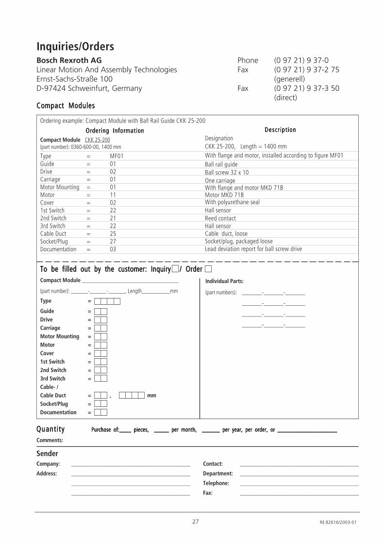
Ordering example: Compact Module with Ball Rail Guide CKK 25-200
Compact ModulesCompact ModulesCompact ModulesCompact ModulesCompact Modules
Ordering InformationOrdering InformationOrdering InformationOrdering InformationOrdering Information DescriptionDescriptionDescriptionDescriptionDescription
To be filled out by the customer: InquiryTo be filled out by the customer: InquiryTo be filled out by the customer: InquiryTo be filled out by the customer: InquiryTo be filled out by the customer: Inquiry / Order/ Order/ Order/ Order/ OrderCompact Module __________________________________
(part number): ______-______-______, Length__________mm
Type =
Guide =Drive =Carriage =Motor Mounting =Motor =Cover =1st Switch =2nd Switch =3rd Switch =Cable- /Cable Duct = , mmSocket/Plug =Documentation =
QuantityQuantityQuantityQuantityQuantity Purchase of:____ pieces, _____ per month, ______ per year, per order, or ____________________Purchase of:____ pieces, _____ per month, ______ per year, per order, or ____________________Purchase of:____ pieces, _____ per month, ______ per year, per order, or ____________________Purchase of:____ pieces, _____ per month, ______ per year, per order, or ____________________Purchase of:____ pieces, _____ per month, ______ per year, per order, or ____________________
Comments:
SenderCompany: _________________________________________ Contact: _________________________________________
Address: _________________________________________ Department: _________________________________________
_________________________________________ Telephone: _________________________________________
_________________________________________ Fax: _________________________________________
Compact Module CKK 25-200(part number): 0360-600-00, 1400 mm
Type = MF01Guide = 01Drive = 02Carriage = 01Motor Mounting = 01Motor = 11Cover = 021st Switch = 222nd Switch = 213rd Switch = 22Cable Duct = 25Socket/Plug = 27Documentation = 03
DesignationCKK 25-200, Length = 1400 mmWith flange and motor, installed according to figure MF01Ball rail guideBall screw 32 x 10One carriageWith flange and motor MKD 71BMotor MKD 71BWith polyurethane sealHall sensorReed contactHall sensorCable duct, looseSocket/plug, packaged looseLead deviation report for ball screw drive
Individual Parts:
(part numbers): _______-_______-_______
_______-_______-_______
_______-_______-_______
_______-_______-_______
Inquiries/OrdersBosch Rexroth AGLinear Motion And Assembly TechnologiesErnst-Sachs-Straße 100D-97424 Schweinfurt, Germany
Phone (0 97 21) 9 37-0Fax (0 97 21) 9 37-2 75
(generell)Fax (0 97 21) 9 37-3 50
(direct)
Subject to technical modifications
Bosch Rexroth AG
Linear Motion and
Assembly Technologies
Ernst-Sachs-Straße 100
D-97424 Schweinfurt, Germany
Telefon (0 97 21) 9 37-0
Telefax (0 97 21) 9 37-2 75 (generell)
Telefax (0 97 21) 9 37-3 50 (direct)
www.boschrexroth.com/brl
e-mail: [email protected]
© Bosch Rexroth AG 2004
Printed in Germany - p 2004/01/3/M
Compact Modules CKK 25-200
RE 82 616/2003-01