Embed Size (px)
Citation preview

RE CRIMSON SOLAR PROJECT
PLAN OF DEVELOPMENT
January 2016

Plan of Development
RE Crimson Solar Project
by Sonoran West Solar Holdings, LLC
Kern County, California
BLM Case File Number CACA‐051967
Prepared for:
Bureau of Land Management
Palm Springs – South Coast Field Office
1201 Bird center Drive
Palm Springs, California 92262
Prepared by:
Recurrent Energy
300 California Street, 7th Floor
San Francisco, CA 94101
Project contact:
Marisa Mitchell, Senior Manager, Site Development
Recurrent Energy
300 California Street, 7th Floor
San Francisco, CA 94901
(415) 967‐3519
January 2016

i
TABLE OF CONTENTS
1. SUMMARY ................................................................................................................................................. 1
2. PROPONENT’S PURPOSE AND NEED ......................................................................................................... 1
3. PROJECT LOCATION ................................................................................................................................... 2
4. EXISTING LAND USE CLASSIFICATION AND APPLICABLE PLANS ................................................................ 2 4.1 BLM Applicable Land Use Plans and Prior NEPA Documents ............................................................. 2
4.2 BLM Land Use Classification ................................................................................................................ 2
4.3 Surrounding Land Uses ....................................................................................................................... 9
5. PROJECT DESCRIPTION .............................................................................................................................. 9
5.1 Photovoltaic Modules and Support Structures ................................................................................... 9
5.2 Inverters and Transformers .............................................................................................................. 10
5.3 Project Substations and Gen‐tie Line ................................................................................................ 10
5.4 Operation and Maintenance Buildings ............................................................................................. 11
5.6 Supervisory Control and Data Acquisition System ............................................................................ 12
5.7 Storage System .................................................................................................................................. 12
5.8 Meteorological Data Collection System ............................................................................................ 12
5.9 Telecommunications Facilities .......................................................................................................... 12
5.10 Access Roads ................................................................................................................................... 12
5.11 Solar Facility Site Safety and Security ............................................................................................. 13
5.12 Water Requirements ....................................................................................................................... 13
5.13 Waste Generation ........................................................................................................................... 14
6. PROJECT CONSTRUCTION AND OPERATION ........................................................................................... 14
6.1 Pre‐construction Activities ................................................................................................................ 14
6.2 Construction Phase 1: Site Preparation ............................................................................................ 15
6.3 Construction Phase 2: Photovoltaic Panel System............................................................................ 16
6.4 Construction Phase 3: Inverters, Transformers, Substation and Electrical Collector System .......... 16
6.5 Construction Site Restoration ........................................................................................................... 17
6.6 Construction Schedule and Workforce ............................................................................................. 17
6.7 Construction Access, Equipment, and Traffic ................................................................................... 18
6.8 Post‐Construction Cleanup ............................................................................................................... 19
6.9 Operation and Maintenance Activities ............................................................................................. 21
6.10 Operation and Maintenance Workforce ......................................................................................... 21
6.11 Site Maintenance ............................................................................................................................ 21
7. FINANCIAL AND TECHNICAL CAPABILITY OF THE APPLICANT ................................................................. 22
8. ENVIRONMENTAL REVIEW ...................................................................................................................... 22
9. OTHER AGENCY INVOLVEMENT .............................................................................................................. 23
FIGURES ....................................................................................................................................................... 24


1
1. SUMMARY
Sonoran West Holdings, LLC (Applicant), a wholly owned subsidiary of Recurrent Energy LLC, proposes to
construct and operate the RE Crimson Solar Project (Project), a utility‐scale solar photovoltaic (PV) and
energy storage project that would be located on federal lands managed by the Bureau of Land
Management (BLM) within the California Desert Conservation Area (CDCA) planning area. This Plan of
Development (POD) has been prepared as part of the SF299 application process for a Right‐of‐Way
(ROW) Grant from BLM.
The Project would interconnect to the regional electrical grid at the Southern California Edison (SCE) 220
kilovolt (kV) Colorado River Substation (CRS). The project would be located on up to 4,000 acres of
public lands. It would generate up to 450 megawatts (MW) of renewable energy using PV technology
and would include up to 450 MW of integrated energy storage capacity. Figure 1 shows the site
development plan.
The Project site was formerly proposed for development as the Sonoran West Solar Energy Generating
Station proposed by BrightSource Energy with submittal of an SF‐299 application for CACA‐051967 in
2009. The former Sonoran West project would have been a 540 MW dual‐turbine power tower project
on approximately 7,000 acres of a combination of BLM‐managed and privately owned land. The current
revised proposal represents a substantial reduction in land use requirements and associated impacts.
2. PROPONENT’S PURPOSE AND NEED
The proponent’s purpose and need is multifaceted. These are to:
Generate up to 450 MW of clean electricity to assist the State of California in achieving its 50 percent renewable portfolio standard for 2030 by providing a significant new source of wholesale renewable energy;
Assist California utilities in meeting their obligations under the CPUC’s Energy Storage Framework and Design Program, including the procurement target of 1,325 MWs by 2020, by providing up to 450 MW of storage capacity;
Develop a site with lower‐impact PV technology in lieu of a higher‐impact power tower technology proposed by the site’s former development sponsor;
Facilitate grid interconnection of intermittent and variable PV generation and minimize line losses associated with off‐site storage by collocating substantial electrical storage capacity at the PV facility site;
Realize economies of scale inherent in constructing a major utility‐scale solar facility on contiguous lands in the immediate vicinity of a high‐voltage interconnection to the CAISO‐controlled grid;
Bring living‐wage skilled jobs to Riverside County through Project development, construction, and operation;
Complement BLM, California Department of Fish and Wildlife (CDFW), and United States Fish and Wildlife Service (USFWS) planning goals and environmental stewardship through proper project siting within the framework of the Desert Renewable Energy Conservation Plan (DRECP);

2
Design the Project collaboratively with tribal and conservation stakeholders in order to avoid, minimize, and mitigate for direct and indirect impacts; and
Compensate for project development impacts by permanently protecting lands with very high natural resource and conservation value.
3. PROJECT LOCATION
The proposed Project is located in unincorporated eastern Riverside County, approximately 13 miles
west of Blythe, just north of Mule Mountain and just south of I‐10, including portions of Sections 1, 2,
11, 12, 13, 24, 25 within Township 7 South, Range 20 East, and portions of Sections 6, 7, 17, 18 within
Township 7 South, Range 21 East. The Project site consists of approximately 4,000 acres of BLM‐
administered land within the Riverside East Solar Energy Zone (SEZ) and within the DRECP Development
Focus Area (DFA) as presented in the Final EIS. The Project is not sited within the adjacent Section 368
Federal Energy Corridor pursuant to the Westwide Energy Corridor Final Programmatic Environmental
Impact Statement (PEIS), except for a short gen‐tie line that would interconnect the Project to the CRS.
The Project site is situated at the east edge of the Chuckwalla Hydrologic Area and supports a broad
alluvial fan that includes many braided washes and channels that converge into a primary channel
flowing into an intra‐state playa lake northwest of the Project site. This playa lake is not a Traditional
Navigable Water; therefore, the channels in the Project area do not qualify as federal jurisdictional
waters.
4. EXISTING LAND USE CLASSIFICATION AND APPLICABLE PLANS
4.1 BLM Applicable Land Use Plans and Prior NEPA Documents
CDCA Plan (1980, as amended). The CDCA Plan covers 25 million acres including the Project site. It is
anticipated that the BLM’s EIS for the Project will analyze consistency with the CDCA Plan, as amended.
A preliminary consistency analysis is included in Section 4.2.
Vegetation Treatments Using Herbicide PEIS (2007). The Project may require the use of herbicide
treatments for weed control, and it is anticipated that the BLM’s EIS for the Project will tier off of the
Vegetation Treatment PEIS.
DRECP Final EIS and Land Use Plan Amendment (LUPA; anticipated 2016). The DRECP was conceived to
be a joint Habitat Conservation Plan and Natural Communities Conservation Plan between the BLM,
California Energy Commission (CEC), CDFW, and USFWS that would streamline renewable energy
permitting. The DRECP is currently in Final EIS form. On March 10, 2015 the DRECP process was
bifurcated, with the BLM LUPA and HCP proceeding ahead of the state NCCP portion of the process. The
LUPA is anticipated to be codified with a Record of Decision during 2016, and will therefore become
applicable to the National Environmental Policy Act (NEPA), Section 106, and ROW Grant processes for
the Project.
4.2 BLM Land Use Classification
The proposed Project site is located on lands currently designated as Multiple‐Use‐Class (MUC)
Moderate (M). Solar electric facilities are allowed under MUC M designation once NEPA requirements

3
are met. The DRECP LUPA is anticipated to designate the site as suitable for solar development without
an additional project‐specific land use plan amendment. It is anticipated that BLM will be able to use the
DRECP LUPA in combination with the project‐specific NEPA documentation to issue a ROW Grant for the
Project, should the BLM elect to do so.

4
Table 1. Multiple Use Class Guidelines Consistency Analysis – Class M Lands
Land Use Activities Multiple‐Use Class M –Moderate Use Consistency of Proposed Project
1. Agriculture Agricultural uses (excluding livestock grazing) are not allowed. Not applicable. Agriculture is not proposed.
2. Air Quality These areas will be managed to protect their air quality and visibility in accordance with Class II objectives of Part C of the Clean Air Act Amendments unless otherwise designated another class by the State of California as a result of recommendations developed by any BLM air-quality management plan.
Class II objectives will be met by the project.
3. Water Quality Areas designated in this class will be managed to minimize degradation of water resources. Best management practices, developed by the Bureau during the planning process outlined in the Clean Water Act, Section 208, and subsequently, will be used to keep impacts on water quality minimal and to comply with Executive Order 12088.
Groundwater will be used pursuant to a groundwater sustainability management plan. Surface waters will be protected to the extent feasible, including designed setbacks from CDFW jurisdictional features.
4. Cultural and Paleontological Resources
Archaeological and paleontological values will be preserved and protected. Procedures described in 36 CFR 800 will be observed where applicable. A Memorandum of Agreement has been signed by the BLM, The California State Historic Preservation Officer, and for cultural resources the President’s Advisory Council on Historic Preservation to protect cultural resources.
Historic properties, if identified on site, shall be protected in accordance with 36 CFR 800 and/or avoided to the extent feasible. Qualified monitors and Native American monitors will monitor all ground-disturbing construction activities. Where appropriate, a paleontological monitor would supervise work that could affect sensitive resources.
5. Native American Values
Native American cultural and religious values will be preserved where relevant and protected where applicable. Native American group(s) shall be consulted. Memorandums of Agreement and Understandings have been signed between BLM and the Native American Heritage Commission pertaining to Native American concerns and cultural resources.
The BLM will consult with Native American Tribes and the Native American Heritage Commission pursuant to Section 106 of the National Historic Preservation Act. In addition, the Proponent has been performing outreach and soliciting design feedback from Native American Tribes since July of 2015.
6. Electrical Generation Facilities
All types of electrical generation plants may be allowed in accordance with State, Federal, and local laws.
Low impact PV development is proposed in lieu of power tower generation.
Nuclear and Fossil Fuel May be allowed in accordance with Federal, State and local laws. Not applicable. Nuclear and fossil fuel generation are not proposed on BLM land.
Wind/Solar May be allowed after NEPA requirements are met. Solar generation is proposed and will meet NEPA requirements.
Geothermal May be allowed pursuant to licenses issued under 43 CFR Section 3250 et seq. NEPA requirements will be met.
Not applicable. Geothermal generation is not proposed on BLM land.
7. Transmission Facilities New gas, electric, and water transmission facilities and cables for interstate communication may be allowed only within designated corridors (see Energy
The gen-tie line is proposed in a designated corridor. NEPA requirements will be met.

5
Table 1. Multiple Use Class Guidelines Consistency Analysis – Class M Lands
Production and Utility Corridors Element). NEPA requirements will be met. Existing facilities within designated corridors may be maintained and upgraded or improved in accordance with existing right-of-way grants or by amendments to right-of-way grants. Existing facilities outside designated corridors may only be maintained but not upgraded or improved.
7a. Distribution Facilities New distribution systems may be allowed and will be placed underground where feasible except where this would have a more detrimental effect on the environment than surface alignment. In addition, new distribution facilities shall be placed within existing rights-of-way where they are reasonably available. Existing facilities may be maintained and upgraded or improved in accordance with existing right-of-way grants.
Not applicable. Distribution facilities are not proposed.
8. Communication Sites New sites may be allowed. NEPA requirements will be met. A 30 day public comment period is required for environmental assessments for long distance line-of-sight communication systems of three or more sites. Existing facilities may be maintained and utilized in accordance with right-of-way grants and applicable regulations.
The applicant seeks a right-of-way grant to construct a solar facility including communications equipment. NEPA requirements will be met.
9. Fire Management Fire suppression measures will be taken in accordance with specific fire management plans subject to such conditions as the authorized officer deems necessary, such as use of motorized vehicle, aircraft, and fire retardant chemicals.
Fire prevention best management practices in accordance with state laws and regulations will be implemented. Fire suppression by vehicle, aircraft, and fire retardant is not proposed.
10. Vegetation Harvesting Native Plants
Removal of vegetation, commercial or non-commercial, may be allowed by permit only after NEPA requirements are met and after development of necessary stipulation.
The applicant seeks a right-of-way grant for construction of a solar facility, including temporary and permanent removal of vegetation. NEPA requirements will be met.
Harvesting by mechanical means
Harvesting by mechanical means may be allowed by permit only. Vegetation relocation may be employed for sensitive species, which will be determined during focused survey efforts.
Rare, threatened, and endangered species, state and federal
All state and federally listed species will be fully protected. Actions which may jeopardize the continued existence of federally listed species will require consultation with the U.S. Fish and Wildlife Service.
State and federal rare, threatened, and endangered species will be avoided to the extent feasible. It is anticipated that BLM will consult with USFWS pursuant to Section 7 of the Endangered Species Act.
Sensitive plant species (including candidates for listing by FWS; FWS
Identified sensitive species will be given protection in management decisions consistent with BLM policies.
Any identified sensitive plants will be avoided or relocated to the extent feasible.

6
Table 1. Multiple Use Class Guidelines Consistency Analysis – Class M Lands
Species of Concern; Species on List 2 CNPS, 1980)
Unusual Plant Assemblages
Identified unusual plant assemblages will be considered when conducting all site-specific environmental impact analyses to minimize impact. See also Wetland/Riparian Areas guidelines.
Any identified unusual plant assemblages will be avoided to the extent feasible.
Vegetation Manipulation 1. Mechanical Control
Mechanical control may be allowed, but only after consideration of possible impacts.
Mechanical control will be evaluated during the NEPA process.
2. Chemical Control Aerial broadcasting application of chemical controls will not be allowed. Spot application will be allowed after site-specific planning. Types and uses of pesticides, in particular herbicides, must conform to Federal, State, and local regulations (see Vegetation Element).
Aerial application of chemical controls is not proposed. Herbicides will be used subject to existing laws, regulations, and a BLM approved weed management plan.
3. Exclosures Exclosures may be allowed. Not applicable. Vegetation exclosures are not proposed.
4. Prescribed Burning Prescribed burning may be allowed after development of a site-specific management plan.
Not applicable. Burning is not proposed.
11. Land Tenure Adjustment
(Applies to Class M and Unclassified lands) Sale of public land may be allowed in accordance with LFPMA and other applicable Federal laws and regulations. Sales in WSAs will not be allowed until after Congressional action.
Not applicable. Land acquisition is not proposed.
12. Livestock Grazing Grazing will be allowed subject to the protection of sensitive resources. Support facilities such as corrals, loading chutes, water developments, and other facilities, permanent or temporary, may be allowed consistent with protection of sensitive resources. Manipulation of vegetation by chemical or mechanical means will not be allowed, except for site-specific needs. (See Vegetation Element.)
Not applicable. Grazing is not proposed.
13. Mineral Exploration and Development
Leasable Minerals: Except as provided in Appendix 5.4, 516, DM 6, NEPA procedures titled “Categorical Exclusions”, prior to approving any lease, notice, or application that was filed pursuant to 43 CFR 3045, 3100, 3500, and S.O. 3087, as amended, an EA will be prepared on the proposed action. Mitigation and reclamation measures will be required to protect and rehabilitate sensitive scenic, ecological, wildlife, vegetative, and cultural values. Locatable Minerals: Location of mining claims in nondiscretionary. Operations on mining claims are subject to the 43 CFR 3809 Regulations and applicable state
Not applicable. Mineral exploration/extraction is not proposed.

7
Table 1. Multiple Use Class Guidelines Consistency Analysis – Class M Lands
and local law. NEPA requirements will be met. BLM will review plans of operations for potential impacts on sensitive resources identified on lands in this class. Mitigation, subject to technical and economic feasibility, will be required. Saleable Minerals: Except as provided in Appendix 5.4, 516 DM 6, NEPA Procedures titled “Categorical Exclusions”, new material sales locations, including sand and gravel sites, will require an EA. Continued use of existing areas of sand and gravel extractions is allowed subject to BLM permits as specified in 43 CFR 3600.
14. Motorized Vehicle Access/Transportation
Motorized-vehicle use will be allowed on “existing” routes of travel unless closed or limited by the authorized officer. New routes may be allowed upon approval of the authorized officer. Vehicle use on some significant dunes and dry lakebeds is allowed (see Motorized Vehicle Access Element). Periodic or seasonal closures or limitations of routes of travel may be required. Access will be provided for mineral exploration and development.
The Applicant seeks a right-of-way grant for construction of a solar facility, including construction of permanent access roads. Such roads will not be open to the public.
Railroads Railroads and trams may be allowed. Not applicable. A railroad is not proposed.
Aircraft Airports and landing strips may be allowed by lease subject to conformance with county or regional airport loans and FAA and DOD approval.
Not applicable. Helicopter use is not proposed.
15. Recreation This class is suitable for a wide range of recreation activities which may involve moderate to high user densities. Recreational opportunities include those permitted in Class L. Competitive motorized vehicle events are limited to “existing” routes of travel and must be approved by the authorized officer. Pit, start, and finish areas must be designated by the authorized officer. All competitive events and organized events having 50 or more vehicles require permits. Permanent or temporary facilities for resource protection and public health and safety are allowed. Trails are open for non-vehicle use and new trails for non-motorized access may be allowed.
Not applicable. No recreation is proposed.
16. Waste Disposal Public lands managed by BLM may not be used for hazardous or non-hazardous waste disposal. Where locations suitable for such disposal are found on BLM managed lands, consideration will be given to transfer of such sites to other ownership for this use. This amendment applies to waste normally handled through land fills or other waste management facilities. It does not apply to mining waste, including tailings and/or chemicals used in processing ore.
Not applicable. No waste site is proposed. Waste will be removed to a landfill facility.

8
Table 1. Multiple Use Class Guidelines Consistency Analysis – Class M Lands
17. Wildlife Species and Habitat Rare, Threatened, and Endangered Species (both state and federal)
All state and federal listed species and their critical habitat will be fully protected. Actions which may affect or jeopardize the continued existence of federally listed species will require formal consultation with the U.S. Fish and Wildlife Service in accordance with Section 7 of the Endangered Species Act.
BLM will consult with the U.S. Fish and Wildlife Service regarding incidental take of state and federally threatened desert tortoise and habitat.
Sensitive Species Identified species will be given protection in management decisions consistent with BLM policies.
Sensitive species will be avoided by design to the extent feasible. Compensation for loss of habitat will be provided.
Predator and Pest Control
Control of depredation wildlife and pests will be allowed in accordance with existing state and federal laws.
Noxious weed control best management practices will be employed, and the project will be designed to ensure minimal perching opportunities for ravens. The project will not attract pests.
Habitat Manipulation Same as Classes C and L, except that chemical and mechanical vegetation manipulation may be allowed.
Not applicable. Habitat improvement is not currently proposed on site.
Reintroduction or Introduction of Established Exotic Species
Reintroduction or introduction of native species or established exotic species is allowed.
Best management practices will ensure introduction of new exotic species will not occur.
18. Wetland/Riparian Areas
Wetland/riparian areas will be considered in all proposed land-use actions. Steps will be taken to provide that these unique characteristics and ecological requirements are managed in accordance with Executive Order 11990, Protection of Wetlands (42 CFR 26951), legislative and Secretarial direction, and BLM Manual 6740, “Wetland Riparian Area Protection and Management” (10/1/79), as outlined in the Vegetation Element.
Riparian vegetation will be avoided by design to the extent feasible.
19. Wild Horses and Burros
Populations of wild and free-roaming horses and burros will be maintained in healthy, stable herds in accordance with the Wild and Free-Roaming Horse and Burro Act of 1971 but will be subject to controls to protect sensitive resources. (See Wild Horse and Burro Element.)
No wild or free-roaming horses or burros are known in the Project area. The project will not affect horses or burros.
9
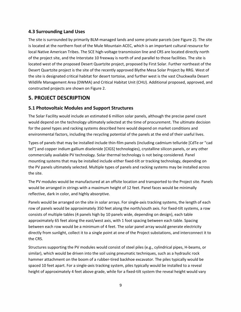
4.3 Surrounding Land Uses
The site is surrounded by primarily BLM‐managed lands and some private parcels (see Figure 2). The site
is located at the northern foot of the Mule Mountain ACEC, which is an important cultural resource for
local Native American Tribes. The SCE high‐voltage transmission line and CRS are located directly north
of the project site, and the Interstate 10 freeway is north of and parallel to those facilities. The site is
located west of the proposed Desert Quartzite project, proposed by First Solar. Further northeast of the
Desert Quartzite project is the site of the recently approved Blythe Mesa Solar Project by RRG. West of
the site is designated critical habitat for desert tortoise, and further west is the vast Chuckwalla Desert
Wildlife Management Area (DWMA) and Critical Habitat Unit (CHU). Additional proposed, approved, and
constructed projects are shown on Figure 2.
5. PROJECT DESCRIPTION
5.1 Photovoltaic Modules and Support Structures
The Solar Facility would include an estimated 6 million solar panels, although the precise panel count
would depend on the technology ultimately selected at the time of procurement. The ultimate decision
for the panel types and racking systems described here would depend on market conditions and
environmental factors, including the recycling potential of the panels at the end of their useful lives.
Types of panels that may be installed include thin‐film panels (including cadmium telluride [CdTe or “cad
tel”] and copper indium gallium diselenide [CIGS] technologies), crystalline silicon panels, or any other
commercially available PV technology. Solar thermal technology is not being considered. Panel
mounting systems that may be installed include either fixed‐tilt or tracking technology, depending on
the PV panels ultimately selected. Multiple types of panels and racking systems may be installed across
the site.
The PV modules would be manufactured at an offsite location and transported to the Project site. Panels
would be arranged in strings with a maximum height of 12 feet. Panel faces would be minimally
reflective, dark in color, and highly absorptive.
Panels would be arranged on the site in solar arrays. For single‐axis tracking systems, the length of each
row of panels would be approximately 350 feet along the north/south axis. For fixed‐tilt systems, a row
consists of multiple tables (4 panels high by 10 panels wide, depending on design), each table
approximately 65 feet along the east/west axis, with 1 foot spacing between each table. Spacing
between each row would be a minimum of 4 feet. The solar panel array would generate electricity
directly from sunlight, collect it to a single point at one of the Project substations, and interconnect it to
the CRS.
Structures supporting the PV modules would consist of steel piles (e.g., cylindrical pipes, H‐beams, or
similar), which would be driven into the soil using pneumatic techniques, such as a hydraulic rock
hammer attachment on the boom of a rubber‐tired backhoe excavator. The piles typically would be
spaced 10 feet apart. For a single‐axis tracking system, piles typically would be installed to a reveal
height of approximately 4 feet above grade, while for a fixed‐tilt system the reveal height would vary

10
based on the racking configuration specified in the final design. For single‐axis tracking systems,
following pile installation the associated motors, torque tubes, and drivelines (if applicable) would be
placed and secured. Some designs allow for PV panels to be secured directly to the torque tubes using
appropriate panel clamps. For some single‐axis tracking systems, and for all fixed‐tilt systems, a
galvanized metal racking system, which secures the PV panels to the installed foundations, would then
be field‐assembled and attached according to the manufacturer’s guidelines.
Fixed‐tilt arrays would be oriented along an east‐west axis with panels facing generally south. Tracking
arrays would be oriented along a north‐south axis with panels tracking east to west to follow the
movement of the sun. The total height of the panel system measured from ground surface would be up
to 12 feet. For fixed‐tilt systems, the panels would be fixed at an approximate 20‐ to 60‐degree angle or
as otherwise determined necessary during final Project design.
Where excavations are required, the majority of proposed construction activities would be limited to
less than 6 feet in depth, however, some excavations, such as those undertaken for the installation of
collector poles and dead‐end structures, may reach depths of 20 feet or more.
5.2 Inverters and Transformers
The Project would be designed and laid out in approximately 2 MW increments which would include an
inverter equipment area measuring 40 feet by 25 feet. However, the final increment sizes ultimately
would depend on available technology and market conditions. Each 2 MW increment would include an
inverter‐transformer station constructed on a concrete pad or steel skid, and centrally located within
the PV arrays. Each inverter‐transformer station would contain up to four inverters, a transformer, a
battery enclosure, and a switchboard 8 to 11 feet high. The pads would contain a security camera at the
top of an approximately 20‐foot pole. If required based on site meteorological conditions, an inverter
shade structure would be installed at each pad. The shade structure would consist of wood or metal
supports and a durable outdoor material shade structure (metal, vinyl, or similar). The shade structure
would extend up to 10 feet above the top of the inverter pad. Inverter pads would result in an estimated
maximum of 4 acres of impervious surfaces at the Project site.
Panels would be electrically connected into panel strings using wiring secured to the panel racking
system. Underground cables, either rated for direct bury or installed in PVC conduit, would be installed
to convey the direct current (DC) electricity from the panels via combiner boxes located throughout the
PV arrays, to inverters to convert the DC to alternating current (AC). The output voltage of the inverters
would be stepped up to the collection system voltage via transformers located in close proximity to the
inverters. The 34.5 kV level collection cables would either be buried underground or installed overhead
on wood poles up to 70 feet tall. Some of the wood poles could be located at the outside edge of the
property line, but a majority of these poles are expected to be located interior to the site. Between 300
and 500 wood poles located at 250‐foot intervals could be installed across the entire site. The typical
height of the poles would be approximately 50 to 60 feet, with diameters varying from 12 to 14 inches.
5.3 Project Substations and Gen‐tie Line
Up to eight substations would transform voltage from 34.5‐kV to 220‐kV. The area of each substation
and associated equipment would be approximately 30,000 square feet (150 feet by 200 feet) in close

11
proximity to the CRS. Each substation would collect consolidated intermediate voltage cables from the
PV collector system. Electrical transformers, switchgear, and related substation facilities would be
designed and constructed to transform medium‐voltage power from the Project’s delivery system to the
220 kV CRS.
Structural components in each substation area would include:
Power transformers (approximately 25 feet by 40 feet, and 25 feet high);
Footings for power transformers;
Pre‐fabricated control buildings (each approximately 23 feet by 15 feet, and 12 feet high) to enclose the protection and control equipment, including relays and low voltage switchgear;
Footings (up to 12 feet deep) for the control enclosure structure;
Metering stand;
Capacitor bank(s);
Circuit breakers and air disconnect switches;
One microwave tower adjacent to the control building comprising a monopole structure up to 100 feet in height mounted with an antenna up to 5 feet in diameter; and
Dead‐end structure(s) up to 80 feet in height to connect the Project substation(s) to the CRS.
The substation area would be graded and compacted to an approximately level grade. Concrete pads
would be constructed on site as foundations for substation equipment, and the remaining area would
be graveled to a maximum depth of approximately 6 inches. Because each of the substation
transformers would contain mineral oil, the substations would be designed to accommodate an
accidental spill of transformer fluid by the use of containment‐style mounting. Each substation would be
surrounded by an up‐to 8‐foot high chain link fence topped with one foot of barbed wire. Each of the
dead‐end structures would require foundations excavated to a depth of 20 feet or more.
The project gen‐tie would be up to 3,000 feet in length, and would be constructed with either
monopoles, lattice steel structures, or wooden H‐frame poles. Structure foundations would be
excavated to a depth of 20 feet or more and include concrete supports depending on final engineering.
Gen‐tie structures would be up to 150 feet tall. The total number of gen‐tie support structures would be
up to 10. A 3‐phase 220 kV conductor would be strung along the gen‐tie line, and the line would be
equipped with a ground wire and a telecommunications fiber‐optic cable.
5.4 Operation and Maintenance Buildings
An operation and maintenance (O&M) building would be located near the Project substations. The O&M
building would be approximately 2,000 square feet in size (approximately 40 feet by 50 feet by 15 feet
at its tallest point), which would accommodate operation and maintenance staff. Two equipment
storage containers measuring 40 feet by 8 feet by 9 feet each also would be located at the substation
area. The O&M building would be constructed on a concrete foundation and would result in an
estimated maximum total of 2 acres of impervious surfaces at the Project site.

12
5.6 Supervisory Control and Data Acquisition System
The facility would be designed with a comprehensive SCADA system to allow remote monitoring of
facility operation and/or remote control of critical components. The fiber optic or other cabling required
for the monitoring system typically would be installed in buried conduit, leading to a SCADA system
cabinet centrally located within the Project site or a series of appropriately located SCADA system
cabinets constructed within the O&M building. The dimensions of each cabinet would be approximately
20 feet by 8 feet by 9 feet high. External telecommunications connections to the SCADA system cabinets
could be provided through wireless or hard wired connections to locally available commercial service
providers.
5.7 Storage System
Storage systems can assist grid operators in more effectively integrating intermittent renewable
resources into the statewide grid and can assist utilities in their efforts to meet energy storage goals
mandated by the CPUC. The Project could include, at the Applicants’ option, a battery or flywheel
storage system capable of storing up to 450 MW of electricity. If provided, the storage system would
consist of battery or flywheel banks housed in electrical enclosures and buried electrical conduit. The
battery system would either be concentrated near the Project substations or dispersed throughout the
Solar Facility site. Up to 3,000 electrical enclosures measuring 40 feet by 8 feet by 8.5 feet high would be
installed on concrete foundations designed for secondary containment, representing up to 12 acres of
impervious surface area. The Project could use any commercially available battery technology, including
but not limited to lithium ion, lead acid, sodium sulfur and sodium or nickel hydride. Battery systems are
operationally silent, and flywheel systems have a noise rating of 45 dBA.
5.8 Meteorological Data Collection System
The Project would include a meteorological (met) data collection system. Each met station would have
multiple weather sensors: a pyranometer for measuring solar irradiance, a thermometer to measure air
temperature, a barometric pressure sensor, and wind sensors to measure speed and direction. The 4‐
foot horizontal cross‐arm of each met system would include the pyranometer mounted on the left hand
side and the two wind sensors installed on a vertical mast to the right. The temperature sensor would be
mounted inside the solar shield behind the main mast. Each sensor would be connected by cable to a
data logger inside the enclosure.
5.9 Telecommunications Facilities
The Project’s SCADA system would interconnect to this fiber optic network at the CRS, and no additional
disturbance associated with telecommunications is anticipated.
5.10 Access Roads
Access to the Project site would be provided from the paved route to the CRS. The Project’s on‐site
roadway system would include a perimeter road, access roads, and internal roads. The perimeter road
and main access roads would be approximately 20 to 30 feet wide and constructed to be consistent with
facility maintenance requirements and BLM FIRE standards. These roads would be surfaced with gravel,
compacted dirt, or another commercially available surface and would provide a fire buffer,

13
accommodate Project O&M activities such as cleaning of solar panels, and facilitate on‐site circulation
for emergency vehicles.
Internal roads would have permeable surfaces and be approximately 12 to 20 feet in width or as
otherwise required by BLM FIRE standards. They would be treated to create a durable, dustless surface
for use during construction and operation. This would not involve lime treatment but would likely
involve surfacing with gravel, compacted native soil, or a dust palliative.
5.11 Solar Facility Site Safety and Security
Controlled Access
Multiple points of ingress/egress would be accessed via locked gates located at multiple points. Each
Project unit would have at least one point of access.
Fencing
The boundary of the Project site would be secured by up‐to 8 foot‐high chain‐link perimeter fences,
topped with three strand barbed wire. The security fence would be collocated with a planned desert
tortoise fence.
Lighting
Motion sensitive, directional security lights would be installed to provide adequate illumination around
the substation areas, each inverter cluster, at gates, and along perimeter fencing. All lighting would be
shielded and directed downward to minimize the potential for glare or spillover onto adjacent
properties.
Other Security Measures
Off‐site security personnel could be dispatched during nighttime hours or could be on‐site, depending
on security risks and operating needs. Infrared security cameras, motion detectors, and/or other similar
technology would be installed to allow for monitoring of the site through review of live footage 24 hours
a day, 7 days a week. Such cameras or other equipment would be placed along the perimeter of the
facility and/or at the inverters. Security cameras located at the inverters would be posted on poles
approximately 20 feet high.
5.12 Water Requirements
Water for construction‐related dust control and operations would be obtained from several potential
sources, including an on‐site or off‐site groundwater well, or trucked from an offsite water purveyor.
During the construction phase, it is anticipated that up to 1,000 acre‐feet would be used per year for
dust suppression (including truck wheel washing) and other purposes. During construction, restroom
facilities would be provided by portable units to be serviced by licensed providers.
During the operation and maintenance phase water would be required for panel washing and
maintenance, and for substation restroom facilities. During operation, the Project would require the use
of approximately 7,300,000 gallons of water (approximately 22 acre‐ft) annually for panel washing and
other uses, equivalent to 16,250 gallons per MW annually. Of this, approximately 563,000 gallons of

14
non‐potable water would be used by employees on‐site for washing or rinsing equipment, hand
washing, and other non‐toilet uses. Approximately 5,400,000 gallons would be used for washing the
panels up to four times a year (up to 1,350,000 gallons of water per washing period).
During operation and maintenance, one or two small above ground portable sanitary waste facilities
may be installed to retain wastewater for employee use. If installed, these facilities would remain on‐
site for the duration of the Project. It is expected that each facility would have a capacity of
approximately 2,000 gallons. These facilities would be installed in accordance with state requirements
and emptied as needed by a contracted wastewater service vehicle. No wastewater would be generated
during panel washing as water would be absorbed into the surrounding soil or would evaporate.
5.13 Waste Generation
Construction of the Project would involve the use of hazardous materials, such as fuels and greases to
fuel and service construction equipment. Such substances may be stored in temporary aboveground
storage tanks or sheds located on the Project site. The fuels stored on‐site would be in a locked
container within a fenced and secure temporary staging area. As the quantities stored may be in excess
of 1,320 gallons, storage would be undertaken in compliance with the Spill Prevention, Control, and
Countermeasure (SPCC) Rule and a Hazardous Materials Business Plan, which would be developed prior
to construction. Trucks and construction vehicles would be serviced from off‐site facilities. The use,
storage, transport, and disposal of hazardous materials used in construction of the facility would be
carried out in accordance with federal, state, and county regulations. No extremely hazardous
substances (i.e., those governed pursuant to Title 40, Part 335 of the Code of Federal Regulations) are
anticipated to be produced, used, stored, transported, or disposed of as a result of project construction.
Material Safety Data Sheets for all applicable materials present on‐site would be made readily available
to on‐site personnel.
Construction materials would be sorted on‐site throughout construction and transported to appropriate
waste management facilities. Recyclable materials would be separated from non‐recyclable items and
stored until they could be transported to a designated recycling facility. It is anticipated that at least 20
percent of construction waste would be recyclable, and 50 percent of those materials would be
recycled. Wooden construction waste (such as wood from wood pallets) would be sold, recycled, or
chipped and composted. Other compostable materials, such as vegetation, might also be composted off‐
site. Non‐hazardous construction materials that cannot be reused or recycled would likely be disposed
of at municipal county landfills. Hazardous waste and electrical waste would not be placed in a landfill,
but rather would be transported to a hazardous waste handling facility (e.g., electronic‐waste recycling).
All contractors and workers would be educated about waste sorting, appropriate recycling storage
areas, and how to reduce landfill waste.
6. PROJECT CONSTRUCTION AND OPERATION
6.1 Pre‐construction Activities
Prior to construction activities along the gen‐tie alignment, a number of activities would be undertaken
to prepare the site and crews for construction. These pre‐construction activities are listed below.

15
Pre‐Construction Surveys
Qualified biologists will conduct pre‐construction surveys for sensitive species. Sensitive resource areas
will be flagged so they are avoided or appropriately managed during construction.
Construction Crew Training
Prior to construction, all contractors, subcontractors, and project personnel would receive Worker
Environmental Awareness Program (WEAP) training regarding the appropriate work practices necessary
to effectively understand and implement the biological commitments in the project description;
implement the mitigation measures; comply with applicable environmental laws and regulations; avoid
and minimize impacts; and understand the importance of these resources and the purpose and
necessity of protecting them. The following species and their habitat would be specifically covered in the
WEAP: desert tortoise, Mojave fringe‐toed lizard, burrowing owl, other raptors and migratory birds,
American badger, and desert kit fox. Applicable sensitive plant species would also be covered in the
WEAP.
Surveying, Staking, and Flagging
Pre‐construction field survey work would include identifying precise locations of the site boundary,
desert tortoise and security fence, and gen‐tie ROW boundary. These features would be subsequently
staked in the field. No paint or permanent discoloring agents would be applied to rocks or vegetation to
indicate survey or construction limits. All off‐road vehicle travel would be monitored by qualified
biologists, archaeologists, and tribal monitors, as appropriate.
Desert Tortoise Fence Installation
A desert tortoise exclusion fence, if required, would be installed per the USFWS protocol. The tortoise
fence would be integrated with the site security fence for maximum durability. Fence installation would
be monitored by qualified biologists, archaeologists, and tribal monitors, as appropriate. Following
installation, clearance surveys would be conducted.
Biological Clearance Surveys
Desert tortoise, mammal, and burrowing owl clearance surveys would be conducted following fence
installation. Mammals and owls would be passively relocated using one‐way doors or other techniques.
Desert tortoise individuals would be actively translocated to an approved site pursuant to an approved
Translocation Plan to be developed in consultation with USFWS and CDFW.
Establishment of Construction Staging Area
A staging area would be established for storing materials, construction equipment, and vehicles. The
staging area would be surveyed and monitored by qualified biologists, archaeologists, and tribal
monitors, as appropriate.
6.2 Construction Phase 1: Site Preparation
Construction‐related Grading and Vegetation Management
16
Across a majority of the site, a low‐impact mow and roll technique would be used to remove surface
vegetation and keep root balls in place. This practice minimizes dust generation and the associated
water requirements related to dust suppression. In addition, this practice allows for faster regeneration
of vegetation cover than re‐seeding alone. In some areas, grubbing and grading will be required to level
particularly rough areas of the site and to prepare soils for concrete foundations for substation
equipment and inverters. Access road beds will also be grubbed, graded, and compacted. The fenceline
will be grubbed and graded to create a level surface for proper fence installation. The site cut and fill
would be approximately balanced; minimal import/export would be necessary.
Erosion and Sediment Control and Pollution Prevention
A Stormwater Pollution Prevention Plan (SWPP) would be prepared by a qualified engineer or erosion
control specialist, and would be implemented before construction. The SWPP would be designed to
reduce potential impacts related to erosion and surface water quality during construction activities and
throughout the life of the Project. It would include Project information and best management practices
(BMP). The BMPs would include dewatering procedures, stormwater runoff quality control measures,
concrete waste management, watering for dust control, and construction of perimeter silt fences, as
needed.
6.3 Construction Phase 2: Photovoltaic Panel System
The structure supporting the PV module arrays would consist of steel piles (e.g., cylindrical pipes, H‐
beams, or similar), which would be driven into the soil using pneumatic techniques, similar to a
hydraulic rock hammer attachment on the boom of a rubber‐tired backhoe excavator. The piles typically
are spaced 10 feet apart. For a single‐axis tracking system, piles typically would be installed to a reveal
height of approximately 4 feet above grade, while for a fixed‐tilt system the reveal height would vary
based on the racking configuration specified in the final design. For single‐axis tracking systems,
following pile installation the associated motors, torque tubes, and drivelines (if applicable) would be
placed and secured. Some designs allow for PV panels to be secured directly to the torque tubes using
appropriate panel clamps. For some single‐axis tracking systems and for all fixed‐tilt systems, a
galvanized metal racking system, which secures the PV panels to the installed foundations, would then
be field‐assembled and attached according to the manufacturer’s guidelines.
6.4 Construction Phase 3: Inverters, Transformers, Substation and Electrical Collector System
Underground cables to connect panel strings would be installed using ordinary trenching techniques,
which typically include a rubber‐tired backhoe excavator or trencher. Wire depths would be in
accordance with local, State, and Federal requirements, and would likely be buried at a minimum of 18
inches below grade, by excavating a trench approximately 3 to 6 feet wide to accommodate the
conduits or direct buried cables. After excavation, cable rated for direct burial or cables installed inside a
polyvinyl chloride (PVC) conduit would be installed in the trench, and, the excavated soil would likely be
used to fill the trench and lightly compressed. All cabling excavations would be to a maximum depth of
10 feet.

17
All electrical inverters and the transformer would be placed on concrete foundation structures or steel
skids. In lieu of steel skids or pre‐cast concrete foundations, foundations for the transformer and
inverter locations would be formed with plywood, and reinforced with structural rebar. Commissioning
of equipment would include testing, calibration of equipment, and troubleshooting. The substation
equipment, inverters, collector system, and PV array systems would be tested prior to commencement
of commercial operations. Upon completion of successful testing, the equipment would be energized.
The eight substation areas would be excavated for the transformer equipment and control building
foundation and oil containment area. The site area for the substations would be graded and compacted
to an approximately level grade. Foundations for the substation would be formed with plywood and
reinforced with structural rebar. Concrete pads would be constructed as foundations for substation
equipment, and the remaining area would be graveled. Concrete for foundations would be brought on‐
site from a batching plant in Blythe or would be batched on site as necessary.
6.5 Construction Site Restoration
Following the completion of major construction, the Project site would be revegetated for the
operations phase pursuant to an approved Restoration Plan. Where necessary, native re‐seeding or
vertical mulching techniques would be used. However, it is anticipated that many species will
regenerate post construction due to the lower‐impact mow and roll technique in lieu of large‐scale
grading.
6.6 Construction Schedule and Workforce
Construction equipment would operate between the hours of 7:00 a.m. and 7:00 p.m. Monday through
Friday for up to a maximum of 8 hours per piece of equipment, daily. Weekend construction work is not
expected to be required, but may occur on occasion, depending on schedule considerations.
Pre‐construction activities would commence in the third quarter of 2017, with desert tortoise clearance
surveys being conducted in September of 2017. Construction activities would commence in the fourth
quarter of 2017, and would be expected to be complete by December of 2019.
Preliminary construction phasing would be as follows:
Pre‐construction Activities, including desert tortoise fence installation: approximately 12 weeks
Phase 1, Site Preparation: approximately 50 weeks
Phase 2, PV Panel System Installation: approximately 40 weeks, overlapping with Phase 1 by approximately 10 weeks
Phase 3, Installation of Inverters, Substations, and Connection: approximately 30 weeks, overlapping with Phase 2 by approximately 16 weeks.

18
Preliminary Construction‐related Employment
Construction Element
Construction Phase
Site
Preparation
Photovoltaic Panel
System Installation
Installation of Inverters,
Substation, and
Connection
Average Number of Workers 250 150 120
Maximum Number of Workers 500 500 200
Length of Phase (work days) 250 200 150
6.7 Construction Access, Equipment, and Traffic
All materials for the Project’s construction would be delivered by truck. The majority of truck traffic
would occur on designated truck routes and major streets. Flatbed trailers and trucks would be used to
transport construction equipment and construction materials to the site. Project components would be
assembled on‐site. Traffic resulting from construction activities would be temporary and could occur
along area roadways as workers and materials are transported to and from the Project site. Materials
deliveries during construction would travel up to 150 miles one way from source to the Project site.
The anticipated preliminary number of vehicle trips for each construction phase of the solar facility is as
follows:
Phase 1: Site Preparation
An average of 250 daily worker round trips with an average travel distance of up to 80 miles to the project site from the surrounding area.
8 trucks per day for foundation delivery
60 water trucks per day
26 flatbed trucks per day
8 trucks per day for module delivery
4 trucks per day for tracker delivery
1 truck per day for gravel delivery
190 pieces of equipment on‐site per day for site preparation
Phase 2: PV Panel and Storage System/Installation
An average of 150 daily worker round trips with an average travel distance of up to 80 miles to the Project site from the surrounding area
1 pickup truck per day
20 water trucks per day
8 trucks per day for delivery of module systems
4 trucks per day for delivery of battery or flywheel systems
4 trucks per week for delivery of tracker systems
200 flatbed trucks per day

19
Phase 3: Inverter, transformer, substation and electrical system installation
An average of 120 average daily worker round trips with an average travel distance of up to 80 miles to the Project site from the surrounding area
1 concrete truck per day
6.8 Post‐Construction Cleanup
Construction sites would be kept in an orderly condition throughout the construction period by using
approved enclosed refuse containers. All refuse and trash would be removed from the site and disposed
of in accordance with BLM and other applicable regulations. No open burning of construction trash
would occur.
All vegetation that may interfere with equipment would be trimmed and removed using manual non‐
mechanical means or sprayed with an approved herbicide, as necessary.
Based on the aridity of the project area and the overall low densities of vegetation present, it is not
likely that vegetation would encroach upon structures so that access would become impaired. However,
noxious weeds and other nonnative invasive plant species could create a fire hazard if allowed to
become established, and invasive weeds could also become problematic from an ecological perspective.
Therefore, weed control activities would be implemented within the project limits.
Weed control activities would include both non‐mechanical and herbicide control methods. Manual
non‐mechanical means of vegetation management would be limited to the use of hand‐operated power
tools and hand tools to cut, clear, or prune herbaceous and woody species. Hand‐operated tools such as
hoes, shovels, and hand saws could be used under the program, as well as hand‐pulling of plants.
Mechanical control activities, such as chaining, disking, grubbing, and mowing using tractors or other
heavy equipment may also be used as necessary.
Herbicide control would involve the use of BLM‐approved herbicides to control weed populations when
manual control methods are not successful in managing the spread of invasive plants. All weed control
using herbicides and adjuvants would be conducted in compliance with California BLM‐approved
chemicals (including manufacturer application rates and use) as identified in the BLM’s 2007 PEIS for
vegetation management using herbicides (BLM 2007) and updated in Information Bulletin No. 2012‐022
(December 2011). The process for treatments would be characterized in a Pesticide Use Proposal
approved by the BLM. Herbicides would likely be necessary to control the spread of invasive weeds
following construction disturbance as part of an integrated pest management strategy. All components
of the weed management approach would comply with the requirements of the Record of Decision for
the 2007 Vegetation Treatments PEIS. Herbicide control would include the following:
Use of Monsanto Corporation glyphosate products, including Roundup PRO® or AquaMaster® herbicides, with Roundup PRO applied in the upland portions of the ROW and AquaMaster applied in the potentially jurisdictional waters of the State or drainages.
Triclopyr (Garlon®) from Dow Agrosciences may be used as an alternative treatment chemical if needed, and would be applied at the manufacturer’s recommended typical application rate.
20
Herbicide would be applied by hand from a backpack sprayer or a truck‐mounted spray rig. The truck mounted spray rig would use individual lines that are applied by hand directly to individual plants and would not use a truck‐mounted boom sprayer, or any broadcast type sprayer. Non‐toxic dye would be added to the mixture to mark areas that have already been treated, thereby avoiding over‐application.
The maximum rate of application for Roundup would be 10.6 quarts per acre per year, and for AquaMaster would be 8 quarts per acre per year.
The intended rate of application is 2% solution for Roundup and 1.5% solution for AquaMaster.
The maximum rate of application for Garlon 4 would be 2 gallons per acre per year.
The pound of active ingredient or acid equivalent would be 8 pounds per acre per year.
Application dates would be intended to cover the entire period of the ROW grant, beginning during the construction phase, if needed.
Treatments would be as needed, upon emergence of the target weed species during the growing season. Growing seasons are typically during the winter months (November to April), but may include the summer months (July to September) if summer rainfall is sufficient to germinate target weed species during those months.
The total number of applications would depend on the extent of weed infestation within the disturbance area, but it is expected that three or more treatment efforts may be required per year. Treatment efforts may be defined as one round of complete coverage for the entire gen‐tie ROW within BLM lands. Rainfall amounts would determine the number of treatment efforts that would be needed, but it is assumed that there would be weed control visits conducted no more than once a month during the winter/spring season. Based on these basic assumptions (three visits per year), there is the potential for approximately 105 annual treatments for the gen‐tie ROW during a 35‐year period.
The primary nonnative species to be targeted are Saharan mustard (Brassica tournefortii), Russian thistle (Salsola tragus), Mediterranean grass (Schismus barbatus), and filaree (Erodium spp.). If additional nonnative plant species are identified during monitoring, these would also be targeted for control efforts.
Crew members who conduct weed treatment in the project area would have extensive experience working around sensitive habitats and species. In addition, crews would be monitored by a restoration ecologist and a desert tortoise monitor. Weed control would be specifically applied to individual plants and not sprayed broadly across the project area.
Crews would work under the direct supervision of a licensed Certified Pesticide Applicator.
Crews would adhere to strict application guidelines when applying herbicide during wind to minimize drift and chemical contact with non‐target vegetation or wildlife. Herbicide application would be suspended if winds are in excess of 6 miles per hour, or if precipitation is occurring or imminent (predicted within the next 24 hours).
The chemicals chosen (glyphosate and triclopyr) have been identified for use due to low likelihood of toxicity to wildlife species, in particular Agassiz’s desert tortoise, as analyzed in BLM’s 2007 Vegetation Treatments PEIS. There is a potential for ingestion of recently treated plants, but an on‐site restoration ecologist and tortoise monitors would minimize this risk. After treatment, the herbicide would dry rapidly in the desert environment and the risk would be further minimized.

21
6.9 Operation and Maintenance Activities
Upon commissioning, the Project would enter the operation phase. The solar modules at the site would
operate during daylight 7 days a week, 365 days a year.
Operational activities at the Project site would include:
Solar module washing;
Vegetation, weed, and pest management;
Security;
Responding to automated electronic alerts based on monitored data, including actual versus expected tolerances for system output and other key performance metrics; and
Communicating with customers, transmission system operators, and other entities involved in facility operations.
6.10 Operation and Maintenance Workforce
Up to 10 permanent staff could be on the site at any one time for ongoing facility maintenance and
repairs if the entire site is operated as a single unit. Alternatively, approximately 2 permanent staff and
8 Project operators would be located off‐site who would be on call to respond to alerts generated by the
monitoring equipment at the Project site. On intermittent occasions, up to 25 workers could be required
on‐site if repairs or replacement of equipment were needed in addition to panel washing. A record of
inspections would be kept on‐site. The duration of scheduled maintenance activities would vary in
accordance with the required task, but could involve up to 40 workers full‐time for up to 2 weeks up to
four times a year for panel washing, and a similar number and duration for workers regularly visiting the
site for routine maintenance activities. The maximum number of staff on‐site at any time would be 50
(40 temporary staff and 10 permanent staff). The personnel and time required for emergency
maintenance would vary in accordance with the necessary response.
6.11 Site Maintenance
The Project site maintenance program would be largely conducted on‐site during daytime hours.
Equipment repairs could take place in the early morning or evening when the plant would be producing
the least amount of energy. Key program elements would include maintenance activities originating
from the on‐site O&M facility.
Maintenance typically would include panel repairs; panel washing; maintenance of transformers,
inverters, and other electrical equipment as needed; and road and fence repairs. Weed management
also would be performed in accordance with an approved Weed Management Plan.
On‐site vegetation would be managed to ensure access to all areas of the site and to screen Project
elements as needed. Solar modules would be washed as needed (up to four times each year) using light
utility vehicles with tow‐behind water trailers, as needed, to maintain optimal electricity production. No
chemical cleaners would be used for module washing.

22
7. FINANCIAL AND TECHNICAL CAPABILITY OF THE APPLICANT
Recurrent Energy is a wholly owned subsidiary of Canadian Solar (NASDAQ:CSIQ). Recurrent has one of
the largest solar photovoltaic development portfolios in North America, including a 3.3 gigawatt
pipeline, more than 1.1 gigawatts of contracted projects, and 520 MW in operating projects. Recurrent
Energy has secured over $4 billion in project financing to date from leading financial lenders and
investors in the energy sector. Recurrent Energy has proven access to capital through a network of
financial partners that enables the delivery of utility solar at any scale. Recurrent has a seasoned
leadership team with experience in conventional and renewable power businesses as well as strong
technology and supply chain expertise to enable delivery of solar projects at market‐leading cost.
8. ENVIRONMENTAL REVIEW
Approval of the Project is a federal action and is thus subject to the environmental analysis
requirements of NEPA. The Project will also require review under the California Environmental Quality
Act (CEQA). It is anticipated that the BLM will coordinate with a CEQA lead agency to prepare a joint
Environmental Impact Statement/Environmental Impact Report (EIS/EIR). Previous environmental
surveys and documentation have been prepared for the project site by URS under contract to
BrightSource Energy, including the following:
Desert Tortoise Protocol Survey (2010)
Mojave Fringe‐toed Lizard Focused Survey (2012)
Western Burrowing Owl Focused Survey (2012)
Elf Owl Focused Survey (2012)
Gila Woodpecker Focused Survey (2012)
Golden Eagle Survey (2012)
Migratory Bird Point Count Transect Survey (2012)
Avian Nocturnal Radar Monitoring (2012)
Baseline Raven Population Survey (2012)
Desert Kit Fox and American Badger Survey (2012)
Bat Acoustic Monitoring Survey (2012‐2013)
Ethnographic Context Report (2012)
Partial Class I Archaeological Records Search (2012)
Partial Class III Intensive Archaeological Field Survey (2012)
Additional environmental surveys, analyses, reports, and plans are currently planned or in preparation
by RE Crimson LLC in support of the SF‐299 application and the BLM’s NEPA process, including the
following:
Spring 2016 Focused Botanical Surveys
Spring 2016 Protocol Desert Tortoise Surveys
Jurisdictional Delineation
Biotechnical Report

23
Complete Class I Archaeological Records Search
Complete Class III Intensive Archaeological Field Survey
Ethnographic Assessment
Geo‐archaological Study
Indirect Effects Study
Paleontological Sensitivity Report
Air Quality Technical Report
Noise Technical Report
Traffic Engineering Report
Water Supply Assessment
Groundwater Pumping Sustainability Plan
Desert Tortoise Translocation Plan
Multi‐species Relocation Plan
Bird and Bat Conservation Strategy
Weed Management Plan
Reclamation and Restoration Plan
Historic Properties Treatment Plan
Historic Properties Management Plan/Long‐term Management Plan
Post‐review Discovery and Unanticipated Effects Plan
NAGPRA Plan of Action
Tribal Participation Plan
9. OTHER AGENCY INVOLVEMENT
The proposed Project may require discretionary permits and approvals from several federal and state
agencies as summarized below:
U.S. Fish and Wildlife Service (USFWS): Endangered Species Act Section 7 authorization for
incidental take of desert tortoise on federal lands, with consultation facilitated by BLM
California Department of Fish and Wildlife (CDFW): Fish and Game Code Section 2081 Incidental
Take Permit for desert tortoise and Section 1600 et. Seq. Streambed Alteration Agreement for
state jurisdictional streambeds
Colorado River Regional Water Quality Control Board (RWQCB): California Code of Regulations
Title 27 Waste Discharge Requirement

FIGURES


Mule Mountain
RE Crimson
Desert SunlightDesert Sunlight
§̈¦I-10
PalenPalen
GenesisGenesis
Former BrightSourceFormer BrightSourceEnergy - SonoranEnergy - Sonoran
West SEGSWest SEGS
Nextera McCoyNextera McCoy
Desert HarvestDesert Harvest
DesertDesertQuartziteQuartzite
NextEra BlytheNextEra Blythe
BlytheBlytheMesaMesa
Patton's Iron MountainDivisional Camp
(ACEC)
Desert LilyPreserve(ACEC)
CornSprings(ACEC)
MuleMountains
(ACEC)
TurtleMountains
(ACEC) ChemehueviDWMA(ACEC)
PalenDry Lake(ACEC)
Chuckwalla ValleyDune Thicket
(ACEC)
ChuckwallaDWMA(ACEC)
SolarSolarReserveReserve
QuartzsiteQuartzsite
Former Rio MesaProject - Proposedfor Conservation
ColoradoRiver IndianReservation
Thurs
day,
Septe
mber
17, 2
015
2:51
:52 PM
C:\R
EGIS\
MyMX
Ds\C
rimso
n_Riv
erside
_CA_
v1_2
0150
819.m
xd
Project AreaOther Solar ProjectsBLM SEZDRECP DevelopmentFocus AreaTribal LandsACEC
RE CrimsonPlan of DevelopmentFigure 2: Surrounding Land UsesCACA 051967