Embed Size (px)
Citation preview

December 28, 2015 Dr. James Karban, Ph.D Environmental Health & Safety Baylor University One Bear Place #97371 Waco, TX 76798-7371 RE: DRAFT SPILL PREVENTION CONTROL & COUNTERMEASURE PLAN, BAYLOR
UNIVERSITY, WACO TEXAS (HRP# BAY4300.WM) Dear Dr. Karban: Enclosed please find the update draft version of the Spill Prevention Control and Countermeasure (SPCC) Plan prepared for Baylor University. This plan outlines annual training requirements and monthly inspections. Please review the plan thoroughly for actions required by your campus. Should you find any part of this plan that requires correction or modification, please notify HRP and we will be happy to make the necessary changes. Following your review, HRP will finalize the plan and issue hard copies. If you have any questions or require additional information, please feel free to contact HRP at 864-289-0311. Sincerely,
Susan Schlangen Jackie Baxley, PE Project Engineer Senior Project Manager Attachment

SPILL PREVENTION CONTROL AND COUNTERMEASURE (SPCC) PLAN Baylor University One Bear Place #97371 Waco, Texas 76798-7371 Prepared For: Baylor University c/o: James Karban One Bear Place #97290 Waco, TX 76798-7290 Prepared By: HRP Associates, Inc. 1327 Miller Road, Suite D Greenville, SC 29607 HRP #: BAY4300.WM Issued: July 2014 December 2015 (Update)

SPCC Plan Waco, TX
Page i of vi
H:\T\ICUT-Texas Independent College\_TX Colleges\Baylor University\2015 SPCC Plan Update\Final\Baylor University SPCC Update 2015.docx
This Spill Prevention Control and Countermeasure (SPCC) Plan was generated at the request of Baylor University by HRP Associates, Inc. It is the privileged property of Baylor University and HRP Associates, Inc., and is not to be distributed to or shared with anyone other than authorized personnel of Baylor University, HRP Associates, Inc., and/or local, state, or federal regulatory or emergency response authorities. This SPCC plan has been certified by a Professional Engineer and an original copy has been retained by HRP Associates, Inc. Any changes or modifications made to this plan (other than non-technical amendments such as changes to phone numbers or names) by Baylor University which are not certified by a Professional Engineer negate the Professional Engineer certification and may lead to a violation of the applicable SPCC regulations.

SPCC Plan Waco, TX
Page ii of vi
H:\T\ICUT-Texas Independent College\_TX Colleges\Baylor University\2015 SPCC Plan Update\Final\Baylor University SPCC Update 2015.docx
TABLE OF CONTENTS
PROFESSIONAL ENGINEER CERTIFICATION .................................................................................... IV
GENERAL FACILITY INFORMATION .................................................................................................... V
COMPLIANCE INSPECTION PLAN REVIEW PAGE ............................................................................. VI
1.0 INTRODUCTION ...................................................................................................................... 1
2.0 FACILITY DESCRIPTION ......................................................................................................... 2 2.1 Facility Operations .............................................................................................................. 2
3.0 RESPONSIBLITIES, NOTIFICATIONS AND REPORTING ......................................................... 3 3.1 Responsibilities .................................................................................................................. 3 3.2 Initial Notifications ............................................................................................................. 3 3.3 Regulatory and Response Notifications for All Spills ............................................................... 3 3.4 Federal Reporting ............................................................................................................... 6 3.5 State Reporting .................................................................................................................. 7
4.0 EMERGENCY PROCEDURES ..................................................................................................... 8
5.0 PAST SPILL EXPERIENCE ...................................................................................................... 10
6.0 POTENTIAL SPILL PREDICTION ............................................................................................ 11 6.1 Oil Capacity and Storage ................................................................................................... 11 6.2 Containment .................................................................................................................... 31 6.3 General Practices ............................................................................................................. 32
6.3.1 Oil Transfer Procedures ......................................................................................... 33 6.3.2 Dike Drainage ...................................................................................................... 34 6.3.3 Recovered Clean-up Material Disposal .................................................................... 34 6.3.4 Visiting Vehicle Traffic ........................................................................................... 34 6.3.5 Drum Handling ..................................................................................................... 35
7.0 INSPECTIONS ........................................................................................................................ 36 7.1 Visual Inspections ............................................................................................................ 36 7.2 Integrity Testing .............................................................................................................. 36
8.0 SPILL ABATEMENT EQUIPMENT AND MATERIALS ................................................................ 40
9.0 SECURITY .............................................................................................................................. 41
10.0 TRAINING .............................................................................................................................. 42
11.0 FACILITY RESPONSE PLAN ................................................................................................... 43
12.0 SPCC PLAN AMENDMENT ...................................................................................................... 44 12.1 Facility Modifications ........................................................................................................ 44 12.2 US EPA Requirements ....................................................................................................... 44 12.3 5-Year Revisions .............................................................................................................. 44
13.0 IMPLEMENTATION SCHEDULE .............................................................................................. 45
SPCC Plan Waco, TX
Page iii of vi
H:\T\ICUT-Texas Independent College\_TX Colleges\Baylor University\2015 SPCC Plan Update\Final\Baylor University SPCC Update 2015.docx
Figures Figure 1 Site Location ........................................................................................ end of text Figure 2 Site Plan .............................................................................................. end of text Figure 3 Emergency Procedures Flowchart ...................................................................... 10 Tables Table 1A Oil Filled Operation Equipment Oil Storage ......................................................... 13 Table 1B Bulk Fuel Storage ............................................................................................. 29 Appendices Appendix A SPCC Regulations 40 CFR Part 112 Appendix B SPCC Rule Cross Reference Appendix C Spill Reporting Form (Example) Appendix D Inspection and Dike Draining Logs Appendix E Certification of the Applicability of the Substantial Harm Criteria Checklist Appendix F Training Roster Appendix G Photo Log of Oil Storage Location

SPCC Plan Waco, TX
Page iv of vi
H:\T\ICUT-Texas Independent College\_TX Colleges\Baylor University\2015 SPCC Plan Update\Final\Baylor University SPCC Update 2015.docx
PROFESSIONAL ENGINEER CERTIFICATION
I hereby certify that (i) I am familiar with the requirements of 40 CFR Part 112, (ii) my agent has visited and examined the facility, (iii) the plan has been prepared in accordance with good engineering practices including the consideration of applicable industry standards, (iv) procedures for required inspections and testing have been established, (v) and the Plan is adequate for the facility.
Tad Goetcheus Printed Name of Registered Professional Engineer HRP Associates 1327 Miller Road Suite D Greenville, SC 29607 (800) 752-3922 ______________________________ Signature of Registered Professional Engineer
(Professional Engineer Seal) Date: ______________ Registration No: 96102 State: Texas Note: This certification is contingent on meeting the action items listed in Section 10.0 of this plan. This certification shall in no way relieve Baylor University of its duty to prepare and fully implement a SPCC Plan in accordance with 40 CFR 112.7, as required by 40 CFR 112.3(a), (b), and (c).

SPCC Plan Waco, TX
Page v of vi
H:\T\ICUT-Texas Independent College\_TX Colleges\Baylor University\2015 SPCC Plan Update\Final\Baylor University SPCC Update 2015.docx
GENERAL FACILITY INFORMATION Name and Location of Facility: Baylor University
One Bear Place #97290 Waco, TX 76798-7290 Type of Facility: Educational Facility Telephone Number: 800-229-5678 Normal Operating Schedule: 24 hours/day; 7 days/week; 52 weeks/year Name and Address of Owner/Operator: Baylor University
One Bear Place #97290 Waco, TX 76798-7290 Designated Person Responsible for James Karban Spill Prevention At the Facility: Environmental Health & Safety Date of Initial Operation of Facility: 1845 Oil Spill History: N/A Receiving Waters: Waco Creek and/or Brazos River
MANAGEMENT APPROVAL
Baylor University is committed to the prevention of discharges of oil to navigable waters and the environment, and maintains the highest standards for spill prevention control and countermeasures through regular reviews, updating and implementation of this SPCC Plan for its facility in Waco, Texas. This SPCC Plan will be implemented as herein described. By signing this document, I certify that I am thoroughly familiar with this SPCC Plan. Signature: ____________________________________________ Authorized Facility Representative: James Karban Title: Director of Environmental Health & Safety

SPCC Plan Waco, TX
Page vi of vi
H:\T\ICUT-Texas Independent College\_TX Colleges\Baylor University\2015 SPCC Plan Update\Final\Baylor University SPCC Update 2015.docx
COMPLIANCE INSPECTION PLAN REVIEW PAGE
In accordance with 40 CFR 112.5(b), a review and evaluation of this SPCC Plan is conducted at least once every five years. As a result of this review and evaluation, Baylor University will amend the SPCC Plan within six months of the review to include more effective prevention and control technology if: (1) such technology will significantly reduce the likelihood of a spill event from the facility, and (2) if such technology has been field-proven at the time of review. Any amendment to the SPCC Plan shall be certified by a Professional Engineer* (in accordance with 40 CFR 112.3(d) within six months after a change in the facility design, construction, operation, or maintenance occurs which materially affects the facility’s potential for the discharge of oil into or upon the navigable waters of the United States or adjoining shorelines.
REVIEW DATE
PLAN UPDATE
REQUIRED (YES/NO)
DESCRIPTION OF REQUIRED REVISION
**SIGNATURE CERTIFYING TO
STATEMENT BELOW
DATE OF AMENDMENT
(IF NECESSARY)
9/25/2015 Yes
Addition/removal of equipment
Administrative Update
will amend will not amend Signature:
___________________ 11/20/2015
will amend will not amend Signature:
___________________
will amend will not amend Signature:
___________________
will amend will not amend Signature:
___________________
CERTIFICATION STATEMENT
*A Professional Engineer’s certification is required if (1) the site maintains oil in excess of 10,000 gallons, (2) the site has a single discharge exceeding 1,000 gallons or two discharges each exceeding 42 gallons within a twelve month period in the three years prior to the SPCC Plan self certification date, or (3) the SPCC Plan deviates from any requirements as allowed by 40 CFR 112.7(a)(2) and 112.7(d) except as provided in 40 CFR 112.6(c). **”I have completed a review and evaluation of the SPCC Plan for Baylor University and will/will not amend the Plan as a result.

SPCC Plan Waco, TX
Page 1 of 45
H:\T\ICUT-Texas Independent College\_TX Colleges\Baylor University\2015 SPCC Plan Update\Final\Baylor University SPCC Update 2015.docx
1.0 INTRODUCTION The Oil Pollution Prevention Regulation in 40 CFR Part 112 was developed in order to (1) prevent oil discharges from reaching navigable waterways (defined to include, but not limited to: lakes, rivers, streams, and wetlands) and adjoining shorelines, and (2) to ensure effective response to oil discharges. Required under this rule is the development of a Spill Prevention Control and Countermeasure Plan (SPCC) for applicable owners, users and/or operators of facilities that could possibly discharge oil in harmful quantities into navigable waterways. On January 14, 2010, the Environmental Protection Agency (EPA) put into effect a final rule amending the SPCC regulations. Under the SPCC requirements, owners or operators of facilities that “drill, produce, gather, store, use, process, refine, transfer, distribute, or consume oil and oil products” must prepare a SPCC if any of the following storage practices apply:
• greater than 1,320 gallons of oil is stored in above-ground containers/tanks, or • greater than 42,000 gallons of oil is stored in underground containers/tanks provided the
underground storage tank (UST) is not subject to the technical requirements of the UST regulations, 40 CFR Part 280 or 281.
Established under the SPCC regulations is a de minimis container size of 55 gallons. Only containers of oil (defined as “oil of any kind or in any form, including, but not limited to… petroleum, fuel, oil, sludge, synthetic oils, mineral oils, oil refuse, or oil mixed with wastes other than dredged spoil”) with a capacity of 55 gallons or greater are counted in the calculation of the 1,320-gallon threshold. All containers with a storage capacity of less than 55 gallons of oil are exempt from the SPCC regulations. A complete copy of the SPCC regulations is included in Appendix A. Baylor University (Baylor) is required to prepare, maintain, and follow a SPCC plan since greater than 1,320 gallons of petroleum products are stored above ground and the discharge of oil could potentially impact Waco Creek and ultimately the Brazos River, located northeast of campus.

SPCC Plan Waco, TX
Page 2 of 45
H:\T\ICUT-Texas Independent College\_TX Colleges\Baylor University\2015 SPCC Plan Update\Final\Baylor University SPCC Update 2015.docx
2.0 FACILITY DESCRIPTION 2.1 Facility Operations Baylor University, located in Waco, Texas is a campus used for educational purposes. Paved parking areas, access road ways, and green areas occupy the areas surrounding the buildings on campus. Baylor University is bordered by Martin Luther King Jr. Blvd to the North, LaSalle Ave to the East, South 9th Street to the South, and Interstate 35 to the West. Baylor University’s total above ground oil storage capacity is approximately 61,400 gallons and includes the following containers with capacities at or exceeding 55-gallons:
• Hydraulic reservoirs (~9,300 gallons) associated with elevators; • Electrical transformers (~25,500 gallons) filled with dielectric fluid (non-PCB); • Various aboveground storage tanks and drums (~17,000 gallons); Used kitchen grease containers (~1,400 gallons); and Diesel reservoirs associated with emergency generators (8,100 gallons).
A site location map has been provided in Figure 1. The location of each storage unit on-site is depicted in Figure 2. A photo log of representative oil storage locations at Baylor University is included as Appendix G. Please note that Figures 1 and 2 have been provided at the end of the text for convenience to the reader and user of this SPCC Plan. Drainage Pathways and Distance to Navigable Waters Facility drainage, based on a visual observation of site contours, is directed to the South of the property towards Waco Creek. Storm drains which direct flow to Waco Creek are located throughout campus. A large volume spill could potentially impact the Brazo River and/or Waco Creek.

SPCC Plan Waco, TX
Page 3 of 45
H:\T\ICUT-Texas Independent College\_TX Colleges\Baylor University\2015 SPCC Plan Update\Final\Baylor University SPCC Update 2015.docx
3.0 RESPONSIBLITIES, NOTIFICATIONS AND REPORTING 3.1 Responsibilities The duties of the Primary Emergency Coordinator and his/her alternate are to routinely inspect all storage and handling facilities and take corrective action when conditions warrant. In addition, the Primary Emergency Coordinator will participate in, set up and maintain: necessary spill emergency procedures; recordkeeping; personnel training; SPCC Plan Reviews and amendments (if required); and reporting requirements. In the event of an oil release, appropriate staff of Baylor University shall carry out the procedures outlined herein under the direction of the Primary Emergency Coordinator or his/her alternates(s). 3.2 Initial Notifications In the event of any emergency or occurrence related to the release or threatened release of petroleum products, the following persons shall be notified immediately:
Name 24 hour phone
Baylor Campus Police 254-710-2222 Cody Rogers 254-640-5098
The Primary Emergency Coordinator and his/her Alternate Emergency Coordinator have been chosen based on the following qualifications:
• Is on-site or on call at all times; • Is familiar with the facility layout; • Is knowledgeable of the locations and characteristics of the materials handled; • Is familiar with all operations and activities at the facility; • Is thoroughly familiar with emergency plans; • Is knowledgeable of the locations of all records; and • Has the authority to commit facility resources in the event of an emergency.
The Emergency Coordinators or designated Alternates will then notify the proper off-site authorities about the actual emergency, following their initial action at the site. Baylor staff does not respond to major spills. Response staff, along with the department involved, will contact campus police who will alert Baylor Environmental as necessary. If the spill is beyond the capacity for campus staff to address, one of the commercial cleanup contractors will be contacted to provide a response. 3.3 Regulatory and Response Notifications for All Spills The guidelines in this section apply to all spills: petroleum products, chemicals, and/or non-hazardous and hazardous waste.

SPCC Plan Waco, TX
Page 4 of 45
H:\T\ICUT-Texas Independent College\_TX Colleges\Baylor University\2015 SPCC Plan Update\Final\Baylor University SPCC Update 2015.docx
1. Texas Requirements (Reference 30 TAC 327) The Texas Commission on Environmental Quality (TCEQ) shall be notified as soon as possible but no later than 24 hours after the discovery of the spill. TCEQ defines a reportable spill as: Petroleum Product and Used Oil - 25 Gallons onto land; or
- Quantity sufficient to create a sheen for spills into water
Crude oil and all other oils not defined as used oil or petroleum product
- 210 Gallons onto land; or - Quantity sufficient to create a sheen for spills
into water Hazardous Substances - A reportable quantity as defined in Table 302.4
in 40 CFR 302.4 for spills onto land; or - The lesser of the 100 lbs or the reportable
quantity as defined in Table 302.4 in 40 CFR 302.4 for spills into water
All other substances - 100 pounds if spilled into water State Emergency Response Commission (TCEQ) (24 hours) Phone: (800) 832-8224 Waco Regional TCEQ Office Phone: (254) 751-0335 The following information will be provided:
• Name, title, affiliation, address and telephone number of reporter; • For discharges from sites on land, the name of the site, street address, municipality, and
the county; • For discharges on, under or into water, the name of the water body, location of the
discharge with reference to a fixed point, description of the area which the discharge may reach;
• Date and time at which the discharge began, the date and time at which the discharge was discovered, and, if the discharge has ended, the date and time at which it ended;
• Common name and quantity of material(s) involved, to the extent known; • An estimate of the quantity discharged; • The identity of any governmental representatives, including authorities or third parties,
responding to the spill; • Any actions taken to contain, clean up and remove the hazardous substance(s) discharged; • The possible hazards to human health or the environment outside the facility; • The extent of injuries, if any; and • The name and address of any person responsible for the discharge (i.e. source of the spill).
2. Spills Threatening to Reach Navigable Waters In the event that a spill of material of any amount threatens to reach navigable waters, the National Response Center in Washington, DC shall be contacted within 24 hours of the event:

SPCC Plan Waco, TX
Page 5 of 45
H:\T\ICUT-Texas Independent College\_TX Colleges\Baylor University\2015 SPCC Plan Update\Final\Baylor University SPCC Update 2015.docx
Authorities Phone Numbers National Response Center (NRC) (800) 424-8802
EPA Region VI (800) 887-6063 If possible, Baylor University personnel will be ready to report the following information to the NRC:
• Your name, location, organization, and telephone number; • Name and address of the party responsible for the incident; • Date and time of the incident; • Location of the incident; • Source and cause of the release or spill; • Types of material(s) released or spilled; • Quantity of materials released or spilled; • Danger or threat posed by the release or spill; • Number and types of injuries (if any); • Weather conditions at the incident location; • Any other information that may help emergency personnel respond to the incident.
Navigable waters of United States are defined in 40 CFR Part 110.1 to include interstate waterways or intrastate waterways including lakes, rivers and streams which may be utilized by interstate travelers for recreational purposes. Navigable waters also include lakes, rivers, and streams from which fish or shellfish are taken. The complete definition may be found in Section 502(7) of the Federal Water Pollution Control Act. In the event of a large volume release, oil products could potentially enter Waco Creek or the Brazo River. Detailed information regarding individual storage areas is provided in Section 6.0. 3. Spills Threatening Human Health In the event the Emergency Coordinator or designated alternate determines that the release of materials threatens human health outside the facility and evacuation may be necessary, he/she will also report his findings to the local authorities, as appropriate:
Authority Phone Numbers TCEQ Emergency Response 800 832-8224
Waco Fire Department 254-750-1700 McLennan County LEPC 254-750-5911
4. Commercial Clean-Up Contractors Should a spill contractor be needed, Baylor University will contact one of the following contractors:
Contractor Phone Numbers Grones Environmental Services 254-829-2796

SPCC Plan Waco, TX
Page 6 of 45
H:\T\ICUT-Texas Independent College\_TX Colleges\Baylor University\2015 SPCC Plan Update\Final\Baylor University SPCC Update 2015.docx
3.4 Federal Reporting After a spill or release of greater than 1,000 gallons or after two spills of greater than 42 gallons within any twelve-month period, or if the spill impacted a navigable waterway, the Emergency Coordinator will report the event(s) to the following agency within 60 days. The Regional Administrator U.S. Environmental Protection Agency – Region IV 1445 Ross Avenue, Suite 1200 Dallas, Texas 75202 Phone: (214) 665-2210 The EPA report will include:
• Name of the facility; • Your name; • Location of the facility; • Maximum storage or handling capacity of the facility and normal daily throughput; • Corrective action and countermeasures you have taken, including a description of
equipment repairs and replacement; • An adequate description of the facility, including maps, flow diagrams, and topographical
maps, as necessary; • The cause of the discharge, including a failure analysis of the system or subsystem in which
the failure occurred; • Additional preventive measures you have taken or contemplated to minimize the possibility
of recurrence; and • Such other information as the Regional Administrator may reasonably require pertinent to
the Plan or spill event. As required by EPA Federal Regulation 40 CFR 112.4(c), a copy of the EPA report will also be submitted to the TCEQ Emergency Response Section at the following address: TCEQ Attn: Emergency Response Section 14250 Judson Rd San Antonio, TX 78233-4480 (210) 490-3096 If 1,000 gallons or more of material is spilled to a navigable waterway, or there are two or more reportable spills (to the National Response Center) in a year, the EPA may conduct an inspection of the site and review this Plan. Following the inspection and review, the EPA may require facility modifications and/or operational changes to minimize the possibility of future spills.

SPCC Plan Waco, TX
Page 7 of 45
H:\T\ICUT-Texas Independent College\_TX Colleges\Baylor University\2015 SPCC Plan Update\Final\Baylor University SPCC Update 2015.docx
3.5 State Reporting For all spills reported to the TCEQ, Baylor University will submit written information in the form of a letter describing the details of the discharge or spill and supporting the adequacy of the response action within 30 days of the discovery of the reportable discharge or spill. The documentation shall contain one of the following items:
• A statement that the discharge or spill response action has been completed and a description of how the response action was conducted. The statement shall include the initial report information outlined in Section 3.3 of this plan;
• A request for an extension of time to complete the response action, along with the reasons
for the request. The request shall also include a projected work schedule outlining the time required to complete the response action. The executive director may grant an extension up to six months from the date the spill or discharge was reported. Unless otherwise notified by the appropriate regional manager or the Emergency Response Team, Baylor University shall proceed according to the terms of the projected work schedule; or
• A statement that the discharge or spill response action has not been completed nor is it
expected to be completed within the maximum allowable six month extension. The statement shall explain why completion of the response action is not feasible and include a projected work schedule outlining the remaining tasks to complete the response action. This information will also serve as notification that the response actions to the discharge or spill will be conducted under the Texas Risk Reduction Program rules in Chapter 350 of the Texas Administrative Coalition. This report will be mailed to:
TCEQ Attn: Emergency Response Section 6801 Sanger Ave Ste 2500 Waco, TX 76710-7826

SPCC Plan Waco, TX
Page 8 of 45
H:\T\ICUT-Texas Independent College\_TX Colleges\Baylor University\2015 SPCC Plan Update\Final\Baylor University SPCC Update 2015.docx
4.0 EMERGENCY PROCEDURES In the event of a spill or release, the emergency procedures outlined in the Emergency Procedures flow chart provided on the following page will be followed. A copy of the emergency procedure flow chart will be in or near the Primary Emergency Coordinator’s office, as well as all of the alternates. If any employee discovers a spill or release, it will immediately be reported to the Primary Emergency Coordinator. If the Primary Emergency Coordinator or alternate determines that the spill or release cannot be handled by on-site personnel and/or may be a threat to either health or the environment, the listed professional spill response contractor (previously listed in Section 3.3) will be contacted. The Primary Emergency Coordinator or Alternate is responsible for determining when a spill event has concluded or is under control sufficiently such that normal activities and personnel presence may be safely resumed. Only if the spill or release can be safely handled by on-site personnel, the following actions may be conducted:
• While awaiting arrival of the Emergency Coordinator or designated Alternates, personnel shall commence containment activities immediately, using all available man-power and spill response materials in the adjacent area of the spill.
• Immediate containment of the spill shall be initiated such as blocking of adjacent interior floor and exterior storm drains, constructing dikes, and using all available containment materials on hand.
• Contained materials will be removed as soon as possible and placed into proper containers, such as 55-gallon drums. All equipment and manpower shall be utilized to remove spilled materials promptly and in a safe manner. All drums used to contain spilled waste will be transported to the waste storage area for eventual off-site disposal by a licensed transporter.

SPCC Plan Waco, TX
Page 9 of 45
H:\T\ICUT-Texas Independent College\_TX Colleges\Baylor University\2015 SPCC Plan Update\Final\Baylor University SPCC Update 2015.docx
EMERGENCY PROCEDURE FLOWCHART: SPILL AND/OR RELEASE OF HAZARDOUS MATERIAL Baylor University, Waco, Texas
CONTACT EMERGENCY COORDINATOR AND/OR SECONDARY COORDINATOR: 24-hour phone 1) Emergency Coordinator – Baylor Campus Police (254) 710-2222 or 911 from campus phone 2) Alternate Emergency Coordinator – Cody Rogers (254) 640-5098 EMERGENCY COORDINATOR OR ALTERNATE OBTAINS THE FOLLOWING INFORMATION:
1) Nature of emergency; 2) Location of emergency; 3) Size and extent of emergency; and 4) Whether Any Personnel are injured or other hazardous situations.
YES
PERSONNEL INJURED? NO
EMERGENCY COORDINATOR OR ALTERNATE CONTACTS THE FOLLOWING: AMBULANCE: 911 POISON CONTROL CENTER 1-800-343-272 BE PREPARED TO GIVE: NAME, ADDRESS, EXTENT OF INJURIES, EXTENT OF EMERGENCY, POSSIBLE CHEMICALS INVOLVED AND QUANTITY.
IF NECESSARY, THE EMERGENCY COORDINATOR WILL ACTIVATE INTERNAL FACILITY ALARMS AND/OR COMMUNICATIONS SYSTEMS TO NOTIFY ALL PERSONNEL OF EVACUATION
IS THE SPILL AN INCIDENTAL RELEASE THAT CAN BE ABSORBED, NEUTRALIZED, OR OTHERWISE CONTROLLED AT THE TIME OF RELEASE BY EMPLOYEES IN THE IMMEDIATE RELEASE AREA OR BY MAINTENANCE PERSONNEL UTILIZING EQUIPMENT ON-HAND
WITHOUT JEOPARDIZING THEIR HEALTH OR SAFETY? YES NO
BEGIN CONTAINING SPILL, CLEAN-UP SPILLED MATERIAL, AND STORE PROPERLY FOR DISPOSAL. EMERGENCY COORDINATOR OR ALTERNATE CONTACTS THE STATE AS NECESSARY (SECTION 3.3) TCEQ: 1-800-832-8224 TCEQ WACO OFFICE: 254-751-0335
EMERGENCY COORDINATOR OR ALTERNATE CONTACTS: TCEQ WACO OFFICE: 254-751-0335 WACO FIRE DEPARTMENT: 254-750-1700 MCLENNAN COUNTY LEPC: 254-750-5911 SPILL CONTRACTOR: Grones Environmental 254-829-2796
HAS SPILL REACHED OR THREATENED WACO CREEK OR HAS ENTERED THE SOIL, WATER OR VOLITILIZED TO THE AIR?
YES NO
EMERGENCY COORDINATOR OR ALTERNATE CONTACTS THE FOLLOWING: NATIONAL RESPONSE CENTER: 800-424-8802 EPA REGION VI: 800-887-6063
SPILL CONTAMINATED MATERIAL CLEANED-UP AND STORED PROPERLY FOR DISPOSAL
REPORTING REQUIREMENTS MET (SECTION 3.4 AND 3.5) AND SPILL FORM (APPENDIX C) COMPLETED
EVENT CONCLUDED

SPCC Plan Waco, TX
Page 10 of 45
H:\T\ICUT-Texas Independent College\_TX Colleges\Baylor University\2015 SPCC Plan Update\Final\Baylor University SPCC Update 2015.docx
5.0 PAST SPILL EXPERIENCE According to 40 CFR 112.7(a), a facility which has experienced one or more spill events within twelve months prior to the effective date of this part should include a written description of each such spill, corrective action taken, and plans for preventing a recurrence. In preparing this plan, no spills having occurred within the past twelve months were identified. Any future spills will be documented using the Spill Form in Appendix C.

SPCC Plan Waco, TX
Page 11 of 45
H:\T\ICUT-Texas Independent College\_TX Colleges\Baylor University\2015 SPCC Plan Update\Final\Baylor University SPCC Update 2015.docx
6.0 POTENTIAL SPILL PREDICTION 6.1 Oil Capacity and Storage
After a review of the Baylor campus, it was determined that all petroleum products are stored and managed at the facility within bulk storage and oil filled operational equipment. Provided in Table 1 is a summary of the oil capacities and containment and control practices identified at Baylor. At any one time, a total of approximately 61,400 gallons of fuel/oil is stored at the facility above ground. Tables 1A and 1B describe the potential type of failure(s), the estimated amount of material which may be released, the probable flow direction if a spill should occur, and existing secondary containment measures in each area of concern. Oil Filled Operational Equipment Oil filled operational equipment includes any oil storage container in which the oil is present solely to support the function of the apparatus or the device. While oil-filled equipment is not subject to the bulk storage container requirements, it must still meet the requirements for general secondary containment. General secondary containment may include:
i. Dikes, berms, or retaining walls sufficiently impervious to contain oil; ii. Curbing iii. Culverting, gutters, or other drainage systems; iv. Weirs, booms, or other barriers; v. Spill diversion ponds; vi. Retention ponds; or vii. Sorbent materials.
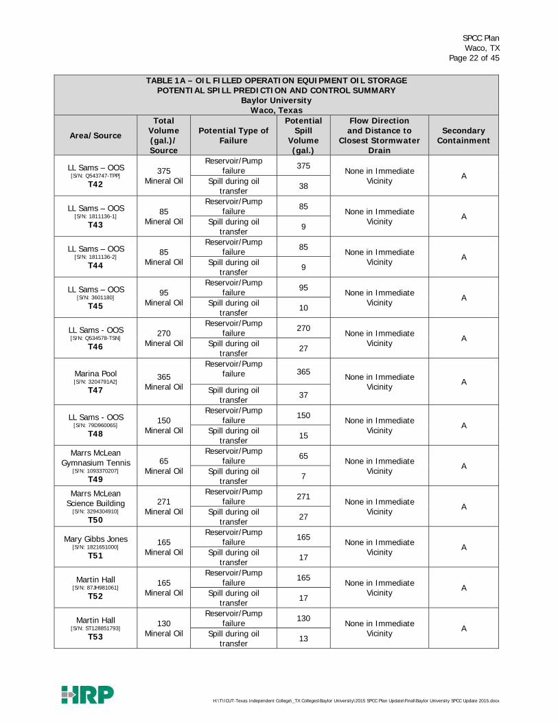
Table 1A is a description of measures for the avoidance and/or containment of the release of materials from the facility associated with oil filled operational equipment.

SPCC Plan Waco, TX
Page 12 of 45
H:\T\ICUT-Texas Independent College\_TX Colleges\Baylor University\2015 SPCC Plan Update\Final\Baylor University SPCC Update 2015.docx
TABLE 1A – OIL FILLED OPERATION EQUIPMENT OIL STORAGE POTENTIAL SPILL PREDICTION AND CONTROL SUMMARY
Baylor University Waco, Texas
Area/Source
Total Volume (gal.)/ Source
Potential Type of Failure
Potential Spill
Volume (gal.)
Flow Direction and Distance to
Closest Stormwater Drain
Secondary Containment
ELEVATOR HYDRAULIC RESERVOIRS (~9,300 gallons)
8th Street Parking Garage #1
E1
135 Hydraulic
Oil
Reservoir/Pump failure 135
Concrete Floor, No access to stormwater A,B
Spill during oil transfer 14
8th Street Parking Garage #2
E2
155 Hydraulic
Oil
Reservoir/Pump failure 155
Concrete Floor, No access to stormwater A,B
Spill during oil transfer 16
Alexander Hall E3
90 Hydraulic
Oil
Reservoir/Pump failure 90
Concrete Floor, No access to stormwater A,B
Spill during oil transfer 9
Armstrong Browning Library
E4
135 Hydraulic
Oil
Reservoir/Pump failure 135
Concrete Floor, No access to stormwater A,B
Spill during oil transfer 14
Baylor Baseball Stadium
E5
93 Hydraulic
Oil
Reservoir/Pump failure 93
Concrete Floor, No access to stormwater A,B
Spill during oil transfer 9
BRIC #1 E6
105 Hydraulic
Oil
Reservoir/Pump failure 105
Concrete Floor, No access to stormwater A,B
Spill during oil transfer 11
BRIC #2 E7
105 Hydraulic
Oil
Reservoir/Pump failure 105
Concrete Floor, No access to stormwater A,B
Spill during oil transfer 11
BRIC #3 E8
105 Hydraulic
Oil
Reservoir/Pump failure 105
Concrete Floor, No access to stormwater A,B
Spill during oil transfer 11
Brooks College #1 E9
105 Hydraulic
Oil
Reservoir/Pump failure 105
Concrete Floor, No access to stormwater A,B
Spill during oil transfer 11
Brooks College #2 E10
105 Hydraulic
Oil
Reservoir/Pump failure 105
Concrete Floor, No access to stormwater A,B Spill during oil
transfer 11
Brooks Flats #1 E11
105 Hydraulic
Oil
Reservoir/Pump failure 105
Concrete Floor, No access to stormwater A,B
Spill during oil transfer 11

SPCC Plan Waco, TX
Page 13 of 45
H:\T\ICUT-Texas Independent College\_TX Colleges\Baylor University\2015 SPCC Plan Update\Final\Baylor University SPCC Update 2015.docx
TABLE 1A – OIL FILLED OPERATION EQUIPMENT OIL STORAGE POTENTIAL SPILL PREDICTION AND CONTROL SUMMARY
Baylor University Waco, Texas
Area/Source
Total Volume (gal.)/ Source
Potential Type of Failure
Potential Spill
Volume (gal.)
Flow Direction and Distance to
Closest Stormwater Drain
Secondary Containment
Brooks Flats #2 E12
94 Hydraulic
Oil
Reservoir/Pump failure 94
Concrete Floor, No access to stormwater A,B
Spill during oil transfer 9
Carrol Library #1 E13
94 Hydraulic
Oil
Reservoir/Pump failure 94
Concrete Floor, No access to stormwater A,B
Spill during oil transfer 9
Carrol Library #2 E14
96 Hydraulic
Oil
Reservoir/Pump failure 96
Concrete Floor, No access to stormwater A,B
Spill during oil transfer 10
Carrol Science #1 E15
90 Hydraulic
Oil
Reservoir/Pump failure 90
Concrete Floor, No access to stormwater A,B
Spill during oil transfer 9
Cashion #3 E16
93 Hydraulic
Oil
Reservoir/Pump failure 93
Concrete Floor, No access to stormwater A,B
Spill during oil transfer 9
Cashion #4 E17
93 Hydraulic
Oil
Reservoir/Pump failure 93
Concrete Floor, No access to stormwater A,B
Spill during oil transfer 9
Castellaw Communication
Center E18
115 Hydraulic
Oil
Reservoir/Pump failure 115
Concrete Floor, No access to stormwater A,B
Spill during oil transfer 12
Crenshaw Student Foundation Center
E19
102 Hydraulic
Oil
Reservoir/Pump failure 102
Concrete Floor, No access to stormwater A,B
Spill during oil transfer 10
Draper North E20
93 Hydraulic
Oil
Reservoir/Pump failure 93
Concrete Floor, No access to stormwater A,B
Spill during oil transfer 9
Draper South E21
140 Hydraulic
Oil
Reservoir/Pump failure 140
Concrete Floor, No access to stormwater A,B
Spill during oil transfer 14
Dutton Parking #1 E22
79 Hydraulic
Oil
Reservoir/Pump failure 79
Concrete Floor, No access to stormwater A,B
Spill during oil transfer 8
Dutton Parking #2 E23
87 Hydraulic
Oil
Reservoir/Pump failure 87
Concrete Floor, No access to stormwater A,B
Spill during oil transfer 9

SPCC Plan Waco, TX
Page 14 of 45
H:\T\ICUT-Texas Independent College\_TX Colleges\Baylor University\2015 SPCC Plan Update\Final\Baylor University SPCC Update 2015.docx
TABLE 1A – OIL FILLED OPERATION EQUIPMENT OIL STORAGE POTENTIAL SPILL PREDICTION AND CONTROL SUMMARY
Baylor University Waco, Texas
Area/Source
Total Volume (gal.)/ Source
Potential Type of Failure
Potential Spill
Volume (gal.)
Flow Direction and Distance to
Closest Stormwater Drain
Secondary Containment
Dutton Parking #3 E24
83 Hydraulic
Oil
Reservoir/Pump failure 83
Concrete Floor, No access to stormwater A,B
Spill during oil transfer 8
East Campus Parking #1
E25
169 Hydraulic
Oil
Reservoir/Pump failure 169
Concrete Floor, No access to stormwater A,B
Spill during oil transfer 17
East Campus Parking #2
E26
169 Hydraulic
Oil
Reservoir/Pump failure 169
Concrete Floor, No access to stormwater A,B
Spill during oil transfer 17
East Campus Parking #3
E27
179 Hydraulic
Oil
Reservoir/Pump failure 179
Concrete Floor, No access to stormwater A,B
Spill during oil transfer 18
Ferrell Center #1 E28
102 Hydraulic
Oil
Reservoir/Pump failure 102
Concrete Floor, No access to stormwater A,B
Spill during oil transfer 10
Ferrell Center #2 E29
102 Hydraulic
Oil
Reservoir/Pump failure 102
Concrete Floor, No access to stormwater A,B
Spill during oil transfer 10
Getterman Field E30
154 Hydraulic
Oil
Reservoir/Pump failure 154
Concrete Floor, No access to stormwater A,B
Spill during oil transfer 15
Hankamer School of Business #1
E31
92 Hydraulic
Oil
Reservoir/Pump failure 92
Concrete Floor, No access to stormwater A,B
Spill during oil transfer 9
Hankamer School of Business #2
E32
92 Hydraulic
Oil
Reservoir/Pump failure 92
Concrete Floor, No access to stormwater A,B
Spill during oil transfer 9
Highers Simpson #1 E33
150 Hydraulic
Oil
Reservoir/Pump failure 150
Concrete Floor, No access to stormwater A,B Spill during oil
transfer 15
Highers Simpson #2 E34
150 Hydraulic
Oil
Reservoir/Pump failure 150
Concrete Floor, No access to stormwater A,B
Spill during oil transfer 15
Highers Simpson #3 E35
150 Hydraulic
Oil
Reservoir/Pump failure 150
Concrete Floor, No access to stormwater A,B
Spill during oil transfer 15

SPCC Plan Waco, TX
Page 15 of 45
H:\T\ICUT-Texas Independent College\_TX Colleges\Baylor University\2015 SPCC Plan Update\Final\Baylor University SPCC Update 2015.docx
TABLE 1A – OIL FILLED OPERATION EQUIPMENT OIL STORAGE POTENTIAL SPILL PREDICTION AND CONTROL SUMMARY
Baylor University Waco, Texas
Area/Source
Total Volume (gal.)/ Source
Potential Type of Failure
Potential Spill
Volume (gal.)
Flow Direction and Distance to
Closest Stormwater Drain
Secondary Containment
Hooper-Schaefer Fine Arts #1
E36
129 Hydraulic
Oil
Reservoir/Pump failure 129
Concrete Floor, No access to stormwater A,B
Spill during oil transfer 13
Hooper-Schaefer Fine Arts #2 (Stage Lift)
E37
129 Hydraulic
Oil
Reservoir/Pump failure 129
Concrete Floor, No access to stormwater A,B
Spill during oil transfer 13
Jesse Jones Library E38
69 Hydraulic
Oil
Reservoir/Pump failure 69
Concrete Floor, No access to stormwater A,B
Spill during oil transfer 7
Marrs McLean Gymnasium #1
E39
107 Hydraulic
Oil
Reservoir/Pump failure 107
Concrete Floor, No access to stormwater A,B Spill during oil
transfer 11
Marrs McLean Gymnasium #2
E40
107 Hydraulic
Oil
Reservoir/Pump failure 107
Concrete Floor, No access to stormwater A,B
Spill during oil transfer 11
Marrs McLean Science Bldg
E41
150 Hydraulic
Oil
Reservoir/Pump failure 150
Concrete Floor, No access to stormwater A,B
Spill during oil transfer 15
Mary Gibbs Jones Building
E42
155 Hydraulic
Oil
Reservoir/Pump failure 155
Concrete Floor, No access to stormwater A,B
Spill during oil transfer 16
Mayborn Museum #1 E43
85 Hydraulic
Oil
Reservoir/Pump failure 85
Concrete Floor, No access to stormwater A,B
Spill during oil transfer 9
Mayborn Museum #2 E44
65 Hydraulic
Oil
Reservoir/Pump failure 65
Concrete Floor, No access to stormwater A,B
Spill during oil transfer 7
Mayborn Museum #3 E45
77 Hydraulic
Oil
Reservoir/Pump failure 77
Concrete Floor, No access to stormwater A,B
Spill during oil transfer 8
Mayborn Museum #4 E46
61 Hydraulic
Oil
Reservoir/Pump failure 61
Concrete Floor, No access to stormwater A,B
Spill during oil transfer 6
Mayborn Museum #5 E47
61 Hydraulic
Oil
Reservoir/Pump failure 61
Concrete Floor, No access to stormwater A,B
Spill during oil transfer 6

SPCC Plan Waco, TX
Page 16 of 45
H:\T\ICUT-Texas Independent College\_TX Colleges\Baylor University\2015 SPCC Plan Update\Final\Baylor University SPCC Update 2015.docx
TABLE 1A – OIL FILLED OPERATION EQUIPMENT OIL STORAGE POTENTIAL SPILL PREDICTION AND CONTROL SUMMARY
Baylor University Waco, Texas
Area/Source
Total Volume (gal.)/ Source
Potential Type of Failure
Potential Spill
Volume (gal.)
Flow Direction and Distance to
Closest Stormwater Drain
Secondary Containment
McCrary Music E48
68 Hydraulic
Oil
Reservoir/Pump failure 68
Concrete Floor, No access to stormwater A,B
Spill during oil transfer 7
McMullen-Connally Center #1
E49
102 Hydraulic
Oil
Reservoir/Pump failure 102
Concrete Floor, No access to stormwater A,B
Spill during oil transfer 10
McMullen-Connally Center #2
E50
102 Hydraulic
Oil
Reservoir/Pump failure 102
Concrete Floor, No access to stormwater A,B
Spill during oil transfer 10
Memorial Residence E51
92 Hydraulic
Oil
Reservoir/Pump failure 92
Concrete Floor, No access to stormwater A,B
Spill during oil transfer 9
Memorial Dining E52
56 Hydraulic
Oil
Reservoir/Pump failure 56
Concrete Floor, No access to stormwater A,B
Spill during oil transfer 6
Morrison Hall E53
135 Hydraulic
Oil
Reservoir/Pump failure 135
Concrete Floor, No access to stormwater A,B
Spill during oil transfer 14
Neil Morris E54
92 Hydraulic
Oil
Reservoir/Pump failure 92
Concrete Floor, No access to stormwater A,B
Spill during oil transfer 9
North Village – Heritage #1
E55
189 Hydraulic
Oil
Reservoir/Pump failure 189
Concrete Floor, No access to stormwater A,B
Spill during oil transfer 19
North Village – Heritage #2
E56
189 Hydraulic
Oil
Reservoir/Pump failure 189
Concrete Floor, No access to stormwater A,B Spill during oil
transfer 19
North Village – Texana
E57
240 Hydraulic
Oil
Reservoir/Pump failure 240
Concrete Floor, No access to stormwater A,B
Spill during oil transfer 24
North Village – University
E58
189 Hydraulic
Oil
Reservoir/Pump failure 189
Concrete Floor, No access to stormwater A,B
Spill during oil transfer 19
Parking Garage 5th Street #1
E59
143 Hydraulic
Oil
Reservoir/Pump failure 143
Concrete Floor, No access to stormwater A,B
Spill during oil transfer 14

SPCC Plan Waco, TX
Page 17 of 45
H:\T\ICUT-Texas Independent College\_TX Colleges\Baylor University\2015 SPCC Plan Update\Final\Baylor University SPCC Update 2015.docx
TABLE 1A – OIL FILLED OPERATION EQUIPMENT OIL STORAGE POTENTIAL SPILL PREDICTION AND CONTROL SUMMARY
Baylor University Waco, Texas
Area/Source
Total Volume (gal.)/ Source
Potential Type of Failure
Potential Spill
Volume (gal.)
Flow Direction and Distance to
Closest Stormwater Drain
Secondary Containment
Parking Garage 5th Street #2
E60
143 Hydraulic
Oil
Reservoir/Pump failure 143
Concrete Floor, No access to stormwater A,B
Spill during oil transfer 14
Poage Library #1 E62
170 Hydraulic
Oil
Reservoir/Pump failure 170
Concrete Floor, No access to stormwater A,B
Spill during oil transfer 17
Poage Library #2 E63
170 Hydraulic
Oil
Reservoir/Pump failure 170
Concrete Floor, No access to stormwater A,B
Spill during oil transfer 17
Rodgers Engineering
E64
101 Hydraulic
Oil
Reservoir/Pump failure 101
Concrete Floor, No access to stormwater A,B
Spill during oil transfer 10
Science Building (BSB) #1
E65
231 Hydraulic
Oil
Reservoir/Pump failure 231
Concrete Floor, No access to stormwater A,B
Spill during oil transfer 23
Science Building (BSB) #2
E66
244 Hydraulic
Oil
Reservoir/Pump failure 244
Concrete Floor, No access to stormwater A,B
Spill during oil transfer 24
Science Building (BSB) #3
E67
272 Hydraulic
Oil
Reservoir/Pump failure 272
Concrete Floor, No access to stormwater A,B
Spill during oil transfer 27
Science Building (BSB) #4
E68
308 Hydraulic
Oil
Reservoir/Pump failure 308
Concrete Floor, No access to stormwater A,B
Spill during oil transfer 31
Speight Plaza #1 E69
109 Hydraulic
Oil
Reservoir/Pump failure 109
Concrete Floor, No access to stormwater A,B
Spill during oil transfer 11
Speight Plaza #2 E70
121 Hydraulic
Oil
Reservoir/Pump failure 121
Concrete Floor, No access to stormwater A,B Spill during oil
transfer 12
Stacey Riddle Forum E71
179 Hydraulic
Oil
Reservoir/Pump failure 179
Concrete Floor, No access to stormwater A,B Spill during oil
transfer 18

SPCC Plan Waco, TX
Page 18 of 45
H:\T\ICUT-Texas Independent College\_TX Colleges\Baylor University\2015 SPCC Plan Update\Final\Baylor University SPCC Update 2015.docx
TABLE 1A – OIL FILLED OPERATION EQUIPMENT OIL STORAGE POTENTIAL SPILL PREDICTION AND CONTROL SUMMARY
Baylor University Waco, Texas
Area/Source
Total Volume (gal.)/ Source
Potential Type of Failure
Potential Spill
Volume (gal.)
Flow Direction and Distance to
Closest Stormwater Drain
Secondary Containment
Student Life Center (BDSUB)
E72
77 Hydraulic
Oil
Reservoir/Pump failure 77
Concrete Floor, No access to stormwater A,B
Spill during oil transfer 8
Truett Seminary E73
124 Hydraulic
Oil
Reservoir/Pump failure 124
Concrete Floor, No access to stormwater A,B
Spill during oil transfer 12
Umphrey Law #1 E74
141 Hydraulic
Oil
Reservoir/Pump failure 141
Concrete Floor, No access to stormwater A,B
Spill during oil transfer 14
Umphrey Law #2 E75
141 Hydraulic
Oil
Reservoir/Pump failure 141
Concrete Floor, No access to stormwater A,B
Spill during oil transfer 14
ELECTRICAL TRANSFORMERS (~25, 500 gallons)
Armstrong Browning Library [S/N: STH895061-M69]
T2
94 Mineral Oil
Reservoir/Pump failure 94
North – 100ft A
Spill during oil transfer 9
LL Sams – OOS [S/N: 73C2209]
T3
65 Mineral Oil
Reservoir/Pump failure 65
None in Vicinity A
Spill during oil transfer 7
Baylor Substation [SN: 801626]
T4
65 Mineral Oil
Reservoir/Pump failure 65
None in Vicinity A
Spill during oil transfer 7
Baylor Substation [SN: 801627]
T5
65 Mineral Oil
Reservoir/Pump failure 65
None in Vicinity A
Spill during oil transfer 7
Baylor Energy Complex #30
[S/N: ST1108A218745]
T6
940 Mineral Oil
Reservoir/Pump failure 940
None in Vicinity A
Spill during oil transfer 94

SPCC Plan Waco, TX
Page 19 of 45
H:\T\ICUT-Texas Independent College\_TX Colleges\Baylor University\2015 SPCC Plan Update\Final\Baylor University SPCC Update 2015.docx
TABLE 1A – OIL FILLED OPERATION EQUIPMENT OIL STORAGE POTENTIAL SPILL PREDICTION AND CONTROL SUMMARY
Baylor University Waco, Texas
Area/Source
Total Volume (gal.)/ Source
Potential Type of Failure
Potential Spill
Volume (gal.)
Flow Direction and Distance to
Closest Stormwater Drain
Secondary Containment
Baylor Energy Complex 40A [S/N: 080627-20S]
T7
500 Mineral Oil
Reservoir/Pump failure 500
None in Vicinity A
Spill during oil transfer 50
Baylor Energy Complex Chiller #1
[S/N: PIK-0846]
T10
508 Mineral Oil
Reservoir/Pump failure 508
None in Vicinity A Spill during oil
transfer 51
Baylor Energy Complex Chiller #6
[S/N: PIC-0167] T11
554 Mineral Oil
Reservoir/Pump failure 554
None in Vicinity A
Spill during oil transfer 55
Baylor Energy Complex Cogen
[S/N: Y590021]
T12
912 Mineral Oil
Reservoir/Pump failure 912
None in Vicinity A
Spill during oil transfer 91
Baylor Energy Complex #1020
[S/N: 2199291405]
T13
713 Mineral Oil
Reservoir/Pump failure 713
None in Vicinity A
Spill during oil transfer 71
Bill Daniel Historic Village
[SN: P502146TUD]
T14
99 Mineral Oil
Reservoir/Pump failure 99
None in Vicinity A
Spill during oil transfer 10
Bill Daniel Student Center
[S/N: 75V2059]
T15
315 Mineral Oil
Reservoir/Pump failure 315
None in Vicinity A
Spill during oil transfer 32
Black Box Opera Building
[S/N: ST060413701]
T16
340 Mineral Oil
Reservoir/Pump failure 340
Southeast – 500ft (directly to Waco Creek) A
Spill during oil transfer 34
Brooks College [S/N: ST0207A18074-1-1]
T17
383 Mineral Oil
Reservoir/Pump failure 383
None in Vicinity A
Spill during oil transfer 38
Brooks Flats [S/N: 4148463106]
T18
279 Mineral Oil
Reservoir/Pump failure 279
None in Vicinity A
Spill during oil transfer 28
Carroll Library [S/N: 93V0710]
T20
210 Mineral Oil
Reservoir/Pump failure 210
None in Immediate Vicinity A
Spill during oil transfer 21

SPCC Plan Waco, TX
Page 20 of 45
H:\T\ICUT-Texas Independent College\_TX Colleges\Baylor University\2015 SPCC Plan Update\Final\Baylor University SPCC Update 2015.docx
TABLE 1A – OIL FILLED OPERATION EQUIPMENT OIL STORAGE POTENTIAL SPILL PREDICTION AND CONTROL SUMMARY
Baylor University Waco, Texas
Area/Source
Total Volume (gal.)/ Source
Potential Type of Failure
Potential Spill
Volume (gal.)
Flow Direction and Distance to
Closest Stormwater Drain
Secondary Containment
Carroll Science [S/N: 701037807]
T21
155 Mineral Oil
Reservoir/Pump failure 155
None in Immediate Vicinity A
Spill during oil transfer 16
Castellaw Communications
Center [S/N: 73A393144]
T22
1502 Mineral Oil
Reservoir/Pump failure 1502
None in Immediate Vicinity A
Spill during oil transfer 150
Collins Hall [S/N: 96-6669-3]
T23
80 Mineral Oil
Reservoir/Pump failure 80
None in Immediate Vicinity A
Spill during oil transfer 8
Collins Hall [S/N: 96-6670-2]
T24
80 Mineral Oil
Reservoir/Pump failure 80
None in Immediate Vicinity A
Spill during oil transfer 8
Collins Hall [S/N: 96-6671-1]
T25
80 Mineral Oil
Reservoir/Pump failure 80
None in Immediate Vicinity A
Spill during oil transfer 8
Crenshaw Student Foundation [S/N: 75V2061]
T26
220 Mineral Oil
Reservoir/Pump failure 220
Northeast – 20 ft A
Spill during oil transfer 20
Draper [S/N: ST1207A19963-1-1]
T27
400 Mineral Oil
Reservoir/Pump failure 400
None in Immediate Vicinity A
Spill during oil transfer 40
East Parking [S/N: 1236528540021]
T28
202 Mineral Oil
Reservoir/Pump failure 202
None in Immediate Vicinity A
Spill during oil transfer 20
East Village – Earle [S/N: 1236L628750001]
T29
445 Mineral Oil
Reservoir/Pump failure 445
None in Immediate Vicinity A
Spill during oil transfer 45
East Village – Teal [S/N: 12JL628750001]
T30
551 Mineral Oil
Reservoir/Pump failure 551
None in Immediate Vicinity A
Spill during oil transfer 55
Ferrell Event Center [S/N: C4637811]
T31
518 Mineral Oil
Reservoir/Pump failure 518
None in Immediate Vicinity A
Spill during oil transfer 52

SPCC Plan Waco, TX
Page 21 of 45
H:\T\ICUT-Texas Independent College\_TX Colleges\Baylor University\2015 SPCC Plan Update\Final\Baylor University SPCC Update 2015.docx
TABLE 1A – OIL FILLED OPERATION EQUIPMENT OIL STORAGE POTENTIAL SPILL PREDICTION AND CONTROL SUMMARY
Baylor University Waco, Texas
Area/Source
Total Volume (gal.)/ Source
Potential Type of Failure
Potential Spill
Volume (gal.)
Flow Direction and Distance to
Closest Stormwater Drain
Secondary Containment
Ferrell Field House [S/N: 75D959070]
T32
100 Mineral Oil
Reservoir/Pump failure 100
None in Immediate Vicinity A
Spill during oil transfer 10
Ferrell Sports Complex
[S/N: 99V4582]
T33
650 Mineral Oil
Reservoir/Pump failure 650
None in Immediate Vicinity A
Spill during oil transfer 65
Fine Arts Center [S/N: 79JK085030]
T34
390 Mineral Oil
Reservoir/Pump failure 390
None in Immediate Vicinity A
Spill during oil transfer 39
Hankamer Business [S/N: 867K593-001]
T35
176 Mineral Oil
Reservoir/Pump failure 176
None in Immediate Vicinity A
Spill during oil transfer 18
Hankamer Business [S/N: M303770RGNA]
T36
150 Mineral Oil
Reservoir/Pump failure 150
None in Immediate Vicinity A
Spill during oil transfer 15
Highers Athletic Complex
[S/N: 5200011]
T37
420 Mineral Oil
Reservoir/Pump failure 420
None in Immediate Vicinity A
Spill during oil transfer 42
Hurd Tennis Center [S/N: Q563028-TXR]
T38
450 Mineral Oil
Reservoir/Pump failure 450
None in Immediate Vicinity A
Spill during oil transfer 45
Jones, Moody, Poage Library
[S/N: 91V7822]
T39
430 Mineral Oil
Reservoir/Pump failure 430
None in Immediate Vicinity A
Spill during oil transfer 43
Kokernot Hall [S/N: 75V2060]
T40
140 Mineral Oil
Reservoir/Pump failure 140
None in Immediate Vicinity A
Spill during oil transfer 14
LL Sams – OOS [S/N: 437016187]
T41
330 Mineral Oil
Reservoir/Pump failure 330
None in Immediate Vicinity A
Spill during oil transfer 33
SPCC Plan Waco, TX
Page 22 of 45
H:\T\ICUT-Texas Independent College\_TX Colleges\Baylor University\2015 SPCC Plan Update\Final\Baylor University SPCC Update 2015.docx
TABLE 1A – OIL FILLED OPERATION EQUIPMENT OIL STORAGE POTENTIAL SPILL PREDICTION AND CONTROL SUMMARY
Baylor University Waco, Texas
Area/Source
Total Volume (gal.)/ Source
Potential Type of Failure
Potential Spill
Volume (gal.)
Flow Direction and Distance to
Closest Stormwater Drain
Secondary Containment
LL Sams – OOS [S/N: Q543747-TPP]
T42
375 Mineral Oil
Reservoir/Pump failure 375
None in Immediate Vicinity A
Spill during oil transfer 38
LL Sams – OOS [S/N: 1811136-1]
T43
85 Mineral Oil
Reservoir/Pump failure 85
None in Immediate Vicinity A
Spill during oil transfer 9
LL Sams – OOS [S/N: 1811136-2]
T44
85 Mineral Oil
Reservoir/Pump failure 85
None in Immediate Vicinity A
Spill during oil transfer 9
LL Sams – OOS [S/N: 3601180]
T45
95 Mineral Oil
Reservoir/Pump failure 95
None in Immediate Vicinity A
Spill during oil transfer 10
LL Sams - OOS [S/N: Q534578-TSN]
T46
270 Mineral Oil
Reservoir/Pump failure 270
None in Immediate Vicinity A
Spill during oil transfer 27
Marina Pool [S/N: 3204791A2]
T47
365 Mineral Oil
Reservoir/Pump failure 365
None in Immediate Vicinity A
Spill during oil transfer 37
LL Sams - OOS [S/N: 79D960065]
T48
150 Mineral Oil
Reservoir/Pump failure 150
None in Immediate Vicinity A
Spill during oil transfer 15
Marrs McLean Gymnasium Tennis
[S/N: 1093370207]
T49
65 Mineral Oil
Reservoir/Pump failure 65
None in Immediate Vicinity A
Spill during oil transfer 7
Marrs McLean Science Building
[S/N: 3294304910]
T50
271 Mineral Oil
Reservoir/Pump failure 271
None in Immediate Vicinity A
Spill during oil transfer 27
Mary Gibbs Jones [S/N: 1821651000]
T51
165 Mineral Oil
Reservoir/Pump failure 165
None in Immediate Vicinity A
Spill during oil transfer 17
Martin Hall [S/N: 87JH981061]
T52
165 Mineral Oil
Reservoir/Pump failure 165
None in Immediate Vicinity A
Spill during oil transfer 17
Martin Hall [S/N: ST128851793]
T53
130 Mineral Oil
Reservoir/Pump failure 130
None in Immediate Vicinity A
Spill during oil transfer 13

SPCC Plan Waco, TX
Page 23 of 45
H:\T\ICUT-Texas Independent College\_TX Colleges\Baylor University\2015 SPCC Plan Update\Final\Baylor University SPCC Update 2015.docx
TABLE 1A – OIL FILLED OPERATION EQUIPMENT OIL STORAGE POTENTIAL SPILL PREDICTION AND CONTROL SUMMARY
Baylor University Waco, Texas
Area/Source
Total Volume (gal.)/ Source
Potential Type of Failure
Potential Spill
Volume (gal.)
Flow Direction and Distance to
Closest Stormwater Drain
Secondary Containment
Martin Hall [S/N: G218832R]
T54
65 Mineral Oil
Reservoir/Pump failure 65
None in Immediate Vicinity A
Spill during oil transfer 7
Mayborn Museum [S/N: 16685898-001-01]
T55
467 Mineral Oil
Reservoir/Pump failure 467
None in Immediate Vicinity A
Spill during oil transfer 47
McCrary Music [S/N: 910693]
T56
300 Mineral Oil
Reservoir/Pump failure 300
None in Immediate Vicinity A
Spill during oil transfer 30
McCrary Music [S/N: 03370000936]
T57
179 Mineral Oil
Reservoir/Pump failure 179
None in Immediate Vicinity A
Spill during oil transfer 18
Memorial Hall [S/N: 726005096]
T58
450 Mineral Oil
Reservoir/Pump failure 450
None in Immediate Vicinity A
Spill during oil transfer 45
Miller Chapel [S/N: ST1213A33069-1]
T59
214 Mineral Oil
Reservoir/Pump failure 214
None in Immediate Vicinity A
Spill during oil transfer 22
Morrison Hall [S/N: Q577341-TST]
T60
265 Mineral Oil
Reservoir/Pump failure 265
None in Immediate Vicinity A
Spill during oil transfer 27
Neil Morris Hall [S/N: 73H54390]
T61
100 Mineral Oil
Reservoir/Pump failure 100
None in Immediate Vicinity A
Spill during oil transfer 10
North Village – Community Center
[S/N: 03B6536]
T62
180 Mineral Oil
Reservoir/Pump failure 180
None in Immediate Vicinity A
Spill during oil transfer 18
North Village – Heritage House
[S/N: 03V6537]
T63
300 Mineral Oil
Reservoir/Pump failure 300
None in Immediate Vicinity A
Spill during oil transfer 30
North Village – Texana House
[S/N: 03V6537]
T64
230 Mineral Oil
Reservoir/Pump failure 230
None in Immediate Vicinity A
Spill during oil transfer 23
North Village – University House
[S/N: 03V6537]
T65
210 Mineral Oil
Reservoir/Pump failure 210
None in Immediate Vicinity A
Spill during oil transfer 21

SPCC Plan Waco, TX
Page 24 of 45
H:\T\ICUT-Texas Independent College\_TX Colleges\Baylor University\2015 SPCC Plan Update\Final\Baylor University SPCC Update 2015.docx
TABLE 1A – OIL FILLED OPERATION EQUIPMENT OIL STORAGE POTENTIAL SPILL PREDICTION AND CONTROL SUMMARY
Baylor University Waco, Texas
Area/Source
Total Volume (gal.)/ Source
Potential Type of Failure
Potential Spill
Volume (gal.)
Flow Direction and Distance to
Closest Stormwater Drain
Secondary Containment
Rogers Comp Bldg [S/N: P179082]
T66
205 Mineral Oil
Reservoir/Pump failure 205
None in Immediate Vicinity A
Spill during oil transfer 21
Russell Gym [S/N: 187921]
T67
151 Mineral Oil
Reservoir/Pump failure 151
None in Immediate Vicinity A
Spill during oil transfer 15
Russell Hall [S/N: 3294314910]
T68
221 Mineral Oil
Reservoir/Pump failure 221
None in Immediate Vicinity A
Spill during oil transfer 22
Sid Richardson [S/N: 3294344910]
T69
279 Mineral Oil
Reservoir/Pump failure 279
None in Immediate Vicinity A
Spill during oil transfer 28
Soccer Field [S/N: F169988]
T70
266 Mineral Oil
Reservoir/Pump failure 266
Southeast – 25 ft A
Spill during oil transfer 27
Speight Plaza Garage
[S/N: 91V8383]
T71
250 Mineral Oil
Reservoir/Pump failure 250
None in Immediate Vicinity A
Spill during oil transfer 25
Speight-Jenkins Apartments [S/N: 01V5674]
T72
80 Mineral Oil
Reservoir/Pump failure 80
None in Immediate Vicinity A
Spill during oil transfer 8
Speight-Jenkins Apartments [S/N: 2215652]
T73
80 Mineral Oil
Reservoir/Pump failure 80
None in Immediate Vicinity A
Spill during oil transfer 8
Speight-Jenkins Apartments
[S/N: PO855418-YRA]
T74
80 Mineral Oil
Reservoir/Pump failure 80
None in Immediate Vicinity A
Spill during oil transfer 8
Stacey Riddle Center
[S/N: 237015011]
T75
422 Mineral Oil
Reservoir/Pump failure 422
None in Immediate Vicinity A
Spill during oil transfer 42
Student Life Center [S/N: ST03V2A-28180-1-1]
T76
375 Mineral Oil
Reservoir/Pump failure 375
North – 50 ft (Waco Creek) A
Spill during oil transfer 38
Truett Building [S/N: Q567078-TPS]
T77
275 Mineral Oil
Reservoir/Pump failure 275
None in Immediate Vicinity A
Spill during oil transfer 28

SPCC Plan Waco, TX
Page 25 of 45
H:\T\ICUT-Texas Independent College\_TX Colleges\Baylor University\2015 SPCC Plan Update\Final\Baylor University SPCC Update 2015.docx
TABLE 1A – OIL FILLED OPERATION EQUIPMENT OIL STORAGE POTENTIAL SPILL PREDICTION AND CONTROL SUMMARY
Baylor University Waco, Texas
Area/Source
Total Volume (gal.)/ Source
Potential Type of Failure
Potential Spill
Volume (gal.)
Flow Direction and Distance to
Closest Stormwater Drain
Secondary Containment
Umphrey Law Center
[S/N: Q561879-TWR]
T78
375 Mineral Oil
Reservoir/Pump failure 375
None in Immediate Vicinity A
Spill during oil transfer 38
BEC Chiller #2 [S/N: 1350006053]
T79
355 Mineral Oil
Reservoir/Pump failure 355
East – 200ft (Waco Creek) A
Spill during oil transfer 36
Penland Dining [S/N: 31409823620]
T80
316 Mineral Oil
Reservoir/Pump failure 316
None in Immediate Vicinity A
Spill during oil transfer 32
LL Sams - OOS [S/N: 5536829]
T81
500 Mineral Oil
Reservoir/Pump failure 500
None in Immediate Vicinity A
Spill during oil transfer 50
Dutton [S/N: 604351103]
T82
176 Mineral Oil
Reservoir/Pump failure 176
Southeast – 20 ft A
Spill during oil transfer 18
Dutton [S/N:16728602-012-01]
T83
750 Mineral Oil
Reservoir/Pump failure 750
Southeast – 20 ft A
Spill during oil transfer 75
Floyd Casey North End Zone [S/N: Q5683550-TSS]
T84
270 Mineral Oil
Reservoir/Pump failure 270
None in Vicinity A
Spill during oil transfer 27
Clyde Hart Track & Field
[S/N: 1459000928]
T85
265 Mineral Oil
Reservoir/Pump failure 265
None in Vicinity A
Spill during oil transfer 27
Elliston Chapel [S/N: 3348734394]
T86
187 Mineral Oil
Reservoir/Pump failure 187
North – 10 ft A
Spill during oil transfer 19
Stadium Boardwalk [S/N: 1450005176]
T87
176 Mineral Oil
Reservoir/Pump failure 176
South – 50 ft A
Spill during oil transfer 18
Tailgate Parking #1 [S/N: 1350011433]
T88
176 Mineral Oil
Reservoir/Pump failure 176
Southwest – 150 ft (Waco Creek) A
Spill during oil transfer 18
Tailgate Parking #2 [S/N: 1350011433]
T89
176 Mineral Oil
Reservoir/Pump failure 176
None in Vicinity A
Spill during oil transfer 18
SPCC Plan Waco, TX
Page 26 of 45
H:\T\ICUT-Texas Independent College\_TX Colleges\Baylor University\2015 SPCC Plan Update\Final\Baylor University SPCC Update 2015.docx
TABLE 1A – OIL FILLED OPERATION EQUIPMENT OIL STORAGE POTENTIAL SPILL PREDICTION AND CONTROL SUMMARY
Baylor University Waco, Texas
Area/Source
Total Volume (gal.)/ Source
Potential Type of Failure
Potential Spill
Volume (gal.)
Flow Direction and Distance to
Closest Stormwater Drain
Secondary Containment
Tailgate Parking #3 [S/N: 135001434]
T90
176 Mineral Oil
Reservoir/Pump failure 176
South – 150 ft (Waco Creek) A
Spill during oil transfer 18
Tailgate Parking #4 [S/N: 1350011432]
T91
176 Mineral Oil
Reservoir/Pump failure 176
None in Vicinity A
Spill during oil transfer 18
South 7th & Alexander Hall
[S/N: 604351103]
T92
65 Mineral Oil
Reservoir/Pump failure 65
None in Vicinity A
Spill during oil transfer 7
Secondary Containment Legend A To be contained by spill kit absorbent materials. B Spill contained by impervious nature of building’s floor and walls C1 Sized Secondary containment via double-walled construction C2 Sized Secondary containment via constructed berm C3 Sized Secondary containment via spill pallet D Electronic Monitoring System E Inadequate containment, see Section 13.0 for implementation schedule
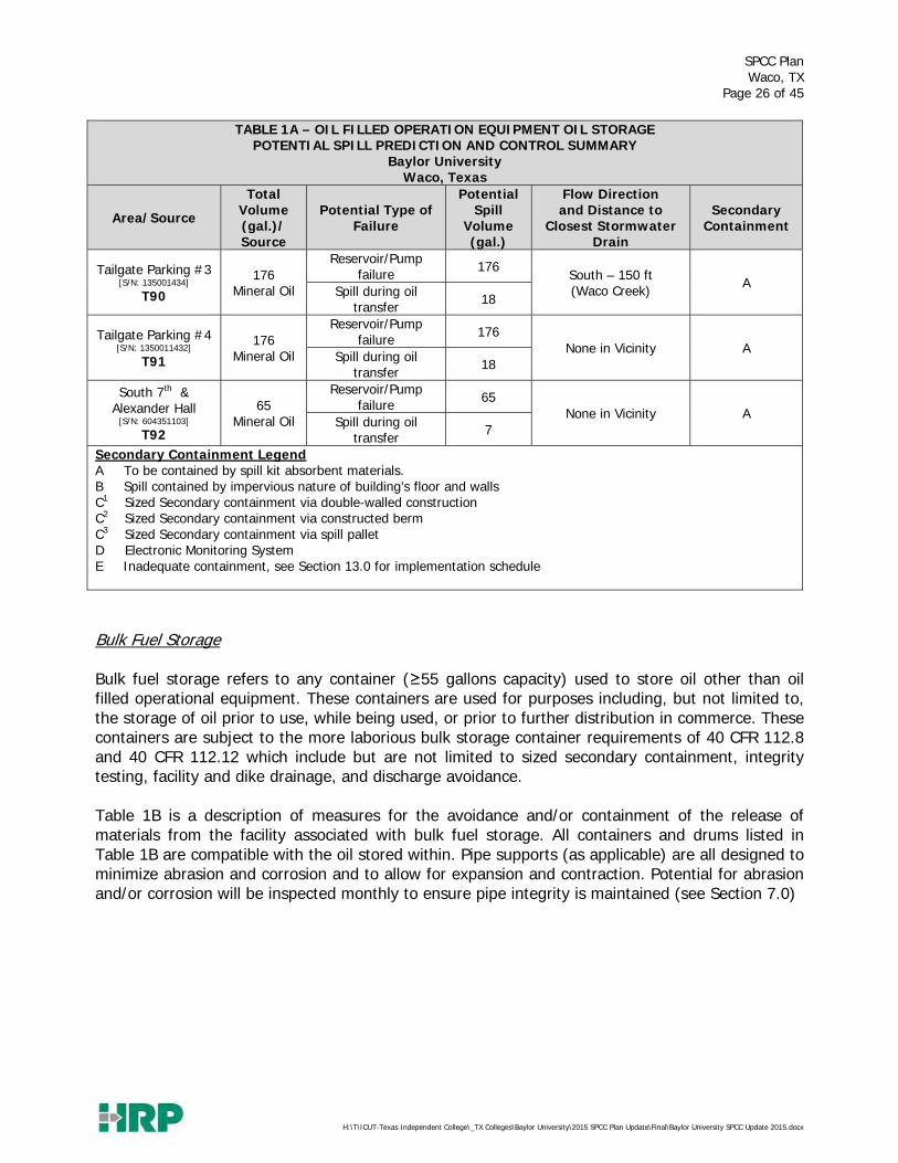
Bulk Fuel Storage Bulk fuel storage refers to any container (≥55 gallons capacity) used to store oil other than oil filled operational equipment. These containers are used for purposes including, but not limited to, the storage of oil prior to use, while being used, or prior to further distribution in commerce. These containers are subject to the more laborious bulk storage container requirements of 40 CFR 112.8 and 40 CFR 112.12 which include but are not limited to sized secondary containment, integrity testing, facility and dike drainage, and discharge avoidance. Table 1B is a description of measures for the avoidance and/or containment of the release of materials from the facility associated with bulk fuel storage. All containers and drums listed in Table 1B are compatible with the oil stored within. Pipe supports (as applicable) are all designed to minimize abrasion and corrosion and to allow for expansion and contraction. Potential for abrasion and/or corrosion will be inspected monthly to ensure pipe integrity is maintained (see Section 7.0)

SPCC Plan Waco, TX
Page 27 of 45
H:\T\ICUT-Texas Independent College\_TX Colleges\Baylor University\2015 SPCC Plan Update\Final\Baylor University SPCC Update 2015.docx
TABLE 1B – BULK FUEL STORAGE POTENTIAL SPILL PREDICTION AND CONTROL SUMMARY
Baylor University Waco, Texas
Area/Source
Total Volume (gal.)/ Source
Potential Type of Failure
Potential Spill
Volume (gal.)
Flow Direction
Overflow Protection/ Discharge Avoidance
Secondary Containment
Dike Draining Protocols
ABOVEGROUND STORAGE TANKS AND DRUMS (~17,000 gallons)
Baylor Energy Complex (AST1)
3 (55) Used Oil
Container Failure 55
Inside building; No storm drain in
immediate vicinity
Visual B N/A Spill during
transfer 6
Baylor Science Building Fire Suppression
(AST 2)
165 Diesel
Container Failure 165
Inside building; No storm drain in
immediate vicinity
Level Gauge B, C1 N/A Spill during
transfer 17
Facility Annex Building
Diesel AST (AST 3)
10,918 Diesel
Container Failure 10,918 Onto paved
surface; storm drain
located 20 ft South
Level Gauge C2
Secondary containment area is not
protected from accumulating rainwater. See Dike Draining Protocols in 6.3.2 and
Appendix C.
Spill during transfer 1092
Facility Annex Building
Gasoline AST (AST 4)
4,075 Gasoline
Container Failure 4,075
Onto paved surface;
storm drain located
10 ft East
Level Gauge C1 N/A Spill during
transfer 408
Facility Annex Building
Used Oil AST (AST 5)
81 Used Oil
Container Failure 81 Onto paved
surface; storm drain
located 20 ft South
See Section 13 C2
Secondary containment area is not
protected from accumulating rainwater. See Dike Draining Protocols in 6.3.2 and
Appendix C.
Spill during transfer 8
Equestrian Center (AST 6)
300 Diesel
Container Failure 300
Onto ground; storm water
culvert located 250
ft East
Level Gauge C2
Secondary containment area is not
protected from accumulating rainwater. See Dike Draining Protocols in 6.3.2 and
Appendix C.
Spill during transfer 30

SPCC Plan Waco, TX
Page 28 of 45
H:\T\ICUT-Texas Independent College\_TX Colleges\Baylor University\2015 SPCC Plan Update\Final\Baylor University SPCC Update 2015.docx
TABLE 1B – BULK FUEL STORAGE POTENTIAL SPILL PREDICTION AND CONTROL SUMMARY
Baylor University Waco, Texas
Area/Source
Total Volume (gal.)/ Source
Potential Type of Failure
Potential Spill
Volume (gal.)
Flow Direction
Overflow Protection/ Discharge Avoidance
Secondary Containment
Dike Draining Protocols
Facility Services (AST 7)
250 Used Oil
Container Failure 250
Onto paved surface; No storm drain in
immediate vicinity
Visual C2 N/A
Containment is covered Spill during
transfer 25
LL Sams (AST 8)
300 Diesel
Container Failure 300 Onto gravel;
No storm drain in
immediate vicinity
Delivery vehicle overfill
sensor C2
Secondary containment area is not
protected from accumulating rainwater. See Dike Draining Protocols in 6.3.2 and
Appendix C.
Spill during transfer 30
LL Sams (AST 9)
550 Gasoline
Container Failure 550
Onto gravel; No storm drain in
immediate vicinity
Delivery vehicle overfill
sensor C2
Secondary containment area is not
protected from accumulating rainwater. See Dike Draining Protocols in 6.3.2 and
Appendix C.
Spill during transfer 55
LL Sams (AST 10)
250 Used Oil
Container Failure 250 Inside
building; No storm drain in
immediate vicinity
Visual B, C2 N/A Spill during
transfer 25
WASTE KITCHEN GREASE STORAGE (1,300 gallons)
Baylor Science Building (KG1)
110 Waste Kitchen Grease
Container Failure 110
Onto paved surface; No storm drain in
immediate vicinity
Visual C1 N/A Spill during
transfer 11
Brooks Dining (KG2)
110 Waste Kitchen Grease
Container Failure 110 Storm drain
located 50 ft North
Visual C1 N/A Spill during
transfer 11
Bill Daniel Student Center
(KG 3)
110 Waste Kitchen Grease
Container Failure 110
Storm drain located 100
ft South Visual C1 N/A
Spill during transfer 11

SPCC Plan Waco, TX
Page 29 of 45
H:\T\ICUT-Texas Independent College\_TX Colleges\Baylor University\2015 SPCC Plan Update\Final\Baylor University SPCC Update 2015.docx
TABLE 1B – BULK FUEL STORAGE POTENTIAL SPILL PREDICTION AND CONTROL SUMMARY
Baylor University Waco, Texas
Area/Source
Total Volume (gal.)/ Source
Potential Type of Failure
Potential Spill
Volume (gal.)
Flow Direction
Overflow Protection/ Discharge Avoidance
Secondary Containment
Dike Draining Protocols
East Village Dining Center
(KG4)
200 Waste Kitchen Grease
Container Failure 200
Onto paved surface; No storm drain in
immediate vicinity
Visual C1 N/A Spill during
transfer 20
Memorial Dining Center (KG5)
110 Waste Kitchen Grease
Container Failure 110 Storm drain
located 10 ft North
Visual C1 N/A Spill during
transfer 11
Penland Kitchen (KG6)
500 Waste Kitchen Grease
Container Failure 500
Onto paved surface; No storm drain in
immediate vicinity
Visual C1 N/A Spill during
transfer 50
McMullen (KG7)
110 Waste Kitchen Grease
Container Failure 110 Storm drain
located 200 ft
Northeast
Visual C1 N/A Spill during
transfer 11
McLane Stadium (KG8)
125 Waste Kitchen Grease
Container Failure 125 Storm drain
located 150 ft West
Visual C1 N/A Spill during
transfer 13
EMERGENCY GENERATOR FUEL STORAGE (8,100 gallons) Armstrong Browning
[S/N: 357536] EG1
60 Diesel
Container Failure 60 Storm drain
located 100 ft North
Level Gauge C1 N/A Spill during
transfer 6
Clifton Robinson Tower
[S/N: 166015] EG2
150 Diesel
Container Failure 150 Inside
building; No storm drain in
immediate vicinity
Level Gauge B N/A Spill during
transfer 15
Draper [S/N: 2099282]
EG3
97 Diesel
Container Failure 97 Storm drain
located 50 ft East
Level Gauge C1 N/A Spill during
transfer 10
Dutton Parking [S/N: D030491798]
EG4
1690 Diesel
Container Failure 1690 Inside
building; No storm drain in
immediate vicinity
Level Gauge B N/A Spill during
transfer 169
Ferrell Center [S/N: G880137100]
EG5
85 Diesel
Container Failure 85
Storm drain located 50 ft Southeast
Level Gauge C1 N/A Spill during
transfer 9
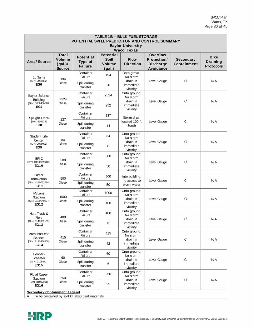
SPCC Plan Waco, TX
Page 30 of 45
H:\T\ICUT-Texas Independent College\_TX Colleges\Baylor University\2015 SPCC Plan Update\Final\Baylor University SPCC Update 2015.docx
TABLE 1B – BULK FUEL STORAGE POTENTIAL SPILL PREDICTION AND CONTROL SUMMARY
Baylor University Waco, Texas
Area/Source
Total Volume (gal.)/ Source
Potential Type of Failure
Potential Spill
Volume (gal.)
Flow Direction
Overflow Protection/ Discharge Avoidance
Secondary Containment
Dike Draining Protocols
LL Sams [S/N: 2091822]
EG6
194 Diesel
Container Failure 194 Onto gravel;
No storm drain in
immediate vicinity
Level Gauge C1 N/A Spill during
transfer 20
Baylor Science Building
[S/N: D030496228] EG7
2524 Diesel
Container Failure 2524 Onto ground;
No storm drain in
immediate vicinity
Level Gauge C1 N/A Spill during
transfer 252
Speight Plaza [S/N: 626923]
EG8
137 Diesel
Container Failure 137 Storm drain
located 100 ft South
Level Gauge C1 N/A Spill during
transfer 14
Student Life Center
[S/N: 2089932] EG9
84 Diesel
Container Failure 84 Onto ground;
No storm drain in
immediate vicinity
Level Gauge C1 N/A Spill during
transfer 8
BRIC [S/N: G1100228818]
EG10
500 Diesel
Container Failure 500 Onto ground;
No storm drain in
immediate vicinity
Level Gauge C1 N/A Spill during
transfer 50
Foster Innovation
[S/N: H140732764] EG11
500 Diesel
Container Failure 500 Into building;
no access to storm water
Level Gauge C1 N/A Spill during
transfer 50
McLane Stadium
[S/N: G130540537] EG12
1000 Diesel
Container Failure 1000 Onto ground;
No storm drain in
immediate vicinity
Level Gauge C1 N/A Spill during
transfer 100
Hart Track & Field
[S/N: E140685169] EG13
400 Diesel
Container Failure 400 Onto ground;
No storm drain in
immediate vicinity
Level Gauge C1 N/A Spill during
transfer 8
Mars MacLean Science
[S/N: B130456368] EG14
415 Diesel
Container Failure 415 Onto ground;
No storm drain in
immediate vicinity
Level Gauge C1 N/A Spill during
transfer 42
Hooper-Schaefer
[S/N: 2105871] EG15
60 Diesel
Container Failure 60 Onto ground;
No storm drain in
immediate vicinity
Level Gauge C1 N/A Spill during
transfer 6
Floyd Casey Stadium
[S/N: BT08J661] EG16
250 Diesel
Container Failure 250 Onto ground;
No storm drain in
immediate vicinity
Level Gauge C1 N/A Spill during
transfer 25
Secondary Containment Legend A To be contained by spill kit absorbent materials.

SPCC Plan Waco, TX
Page 31 of 45
H:\T\ICUT-Texas Independent College\_TX Colleges\Baylor University\2015 SPCC Plan Update\Final\Baylor University SPCC Update 2015.docx
TABLE 1B – BULK FUEL STORAGE POTENTIAL SPILL PREDICTION AND CONTROL SUMMARY
Baylor University Waco, Texas
Area/Source
Total Volume (gal.)/ Source
Potential Type of Failure
Potential Spill
Volume (gal.)
Flow Direction
Overflow Protection/ Discharge Avoidance
Secondary Containment
Dike Draining Protocols
B Spill contained by impervious nature of building’s floor and walls C1 Sized Secondary containment via double-walled construction C2 Sized Secondary containment via constructed berm C3 Sized Secondary containment via spill pallet D Electronic Monitoring System E Inadequate containment, see Section 13.0 for implementation schedule
6.2 Containment 1. Hydraulic Elevators and Transformers (Oil-Filled Operating Equipment)
Numerous (74) hydraulic elevators, with hydraulic fluid capacities at or exceeding 55-gallons, are located throughout Baylor University’s campus in various buildings. Numerous electrical transformers with dielectric fluid (mineral oil) capacities at or exceeding 55-gallons are located throughout campus. Photos of typical hydraulic oil reservoirs and electrical transformers located at Baylor are included in Appendix G. Existing Containment and Safeguards The hydraulic oil reservoirs for each elevator are located in locked elevator or mechanical rooms that are only accessible by authorized personnel. The walls and concrete floors of the elevator mechanical rooms provide for a majority of the secondary containment. Electrical transformers containing dielectric fluid remain locked and are generally located away from high-traffic areas. Oil filled operational equipment is subject to general containment requirements. Containment methods implemented include being located indoors for elevator reservoirs, having sorbent material readily available as outlined in Section 8.0, and conducting periodic inspections as outlined in Section 7.1. 2. Waste Kitchen Grease Storage Eight (8) containers are located on Baylor University’s campus at different dining center locations. These containers are serviced from their respective locations by an outside vendor. Existing Containment and Safeguards The containers of waste kitchen grease are typically located in loading dock areas discharging onto surrounding paved areas and/or adjacent storm water drains. All tanks are double-walled, providing adequate secondary containment.
SPCC Plan Waco, TX
Page 32 of 45
H:\T\ICUT-Texas Independent College\_TX Colleges\Baylor University\2015 SPCC Plan Update\Final\Baylor University SPCC Update 2015.docx
Baylor will regularly inspect the kitchen grease units for leaks or releases as outlined in Section 7.1. 3. Above Ground Storage - Drums 55-gallon drums of used oil are located at the Baylor Energy Complex. As much as possible, Baylor Facilities Services has adopted the practice of ordering oil in drums less than 55 gallon; thus reducing its oil inventory and risk as managed by the SPCC rules. Existing Containment and Safeguards The 55-gallon drums are located inside the building, which provides adequate secondary containment for the containers. Baylor University will regularly inspect the 55-gallon drums for leaks or releases as outlined in Section 7.1. Overfill protection is addressed by maintenance staff visually gauging the available capacity remaining in the container prior to manually filling the drum. 4. Above Ground Storage – Tanks Two (2) gasoline ASTs, four (4) diesel ASTs, and three (3) used oil ASTs are located throughout the campus. Existing Containment and Safeguards All ASTs are either provided with a double walled construction or lie within containment areas, which provide secondary containment for the ASTs. Each tank will be inspected monthly as outlined in Section 7.1. 5. Emergency Generator Diesel Fuel Reservoir
Sixteen (6) emergency generators with diesel fuel reservoirs are located throughout the Baylor campus. Existing Containment and Safeguards The emergency generator diesel fuel storage tanks are either provided with a double-walled construction or located within a concrete building providing adequate secondary containment. Each tank will be inspected monthly as outlined in Section 7.1. 6.3 General Practices

SPCC Plan Waco, TX
Page 33 of 45
H:\T\ICUT-Texas Independent College\_TX Colleges\Baylor University\2015 SPCC Plan Update\Final\Baylor University SPCC Update 2015.docx
6.3.1 Oil Transfer Procedures and Overfill Protection 1. Elevators & Transformers During the removal or addition of oil, relative to elevators or transformers, Baylor University personnel, or trained contractors acting on their behalf, will supervise these operations if they are being performed by an outside contractor. If trained Baylor Personnel are not in attendance during such activities, the contractor will be informed by Baylor Personnel, or trained contractors acting on their behalf, of the emergency response procedures outlined in this plan. Specifically, the contractor will be notified of whom to call on campus in case of a spill or release. 2. Kitchen Grease Baylor University personnel, or trained food services contractors acting on their behalf, will use caution when adding waste kitchen grease to the storage container. Prior to the transfer of used kitchen grease to the storage container, personnel will note the level within the container to ensure adequate capacity is available. Baylor University personnel, or trained food services contractors acting on their behalf, will oversee the removal of the waste kitchen grease when vacuum pumped by the disposal contractor to ensure proper procedures and precautions are taken to minimize any releases. Baylor personnel, or trained food services contractors acting on Baylor’s behalf, will be present at all off-loading events. To reduce the potential for a spill to a storm water drain, grease will not be added to or removed from the container during a heavy rain event, if at all possible.
3. Above Ground Storage – Drums Oils are consumed from smaller containers and are added to drums. Overfill protection is addressed by maintenance staff visually gauging the available capacity remaining in the container prior to manually filling the drum. Care will be taken to minimize releases. Baylor personnel, or trained contractors acting on Baylor’s behalf, will be present at all times when vendors are loading or unloading used drums.
4. Above Ground Storage Tanks (Including Emergency Generators) During delivery of fuel to the ASTs throughout campus, the delivery truck’s tires will be chocked and hand brake set. During fuel transfers, the delivery truck driver and trained Baylor University personnel, or trained contractors acting on Baylor’s behalf, will observe the filling level of material in the tank via a visual tank gauge or automatic cut off system as indicated in Table 1B to ensure no spills occur. In addition, before and after delivery, all valves on the truck and tank will be inspected to ensure none are leaking and all are secured. To meet the requirements of overfill protection Baylor will ensure that:
Adequate capacity is available to receive the delivery; a receipt is obtained; and

SPCC Plan Waco, TX
Page 34 of 45
H:\T\ICUT-Texas Independent College\_TX Colleges\Baylor University\2015 SPCC Plan Update\Final\Baylor University SPCC Update 2015.docx
stormwater drains or ditches are protected from a spill or release. The ports of the ASTs will be locked after the delivery is complete. If at all possible, to reduce the potential for a spill to a storm water drain, fuel oil, diesel or gasoline will not be off loaded or unloaded during a heavy rain event, if at all possible. 6.3.2 Dike Drainage In case of rainwater accumulation, a draining log will be used to document all dike or secondary containment draining activities. The draining log, available in Appendix D, outlines the draining procedures which entail trained Baylor personnel, or trained contractors acting on Baylor’s behalf, conducting the following:
visually inspect the contained rainwater for evidence of an oily sheen or film; visually inspect the contained rainwater for evidence of color; visually inspect the contained rainwater for evidence of oil sludge or deposits. If there is any evidence of an oily sheen or film, discoloration, or oily sludge or deposits,
the material will NOT be drained to the ground. Instead an outside contractor will be contacted to vacuum the contained fuel/oil/water mixture and dispose in accordance with the resulting waste stream determination.
If the containment area is drained to the ground, trained personnel will monitor the entire draining event (i.e. not leave that dike or containment area while the dike is being drained). Additionally, all drain lines will be securely closed and locked after the event.
6.3.3 Recovered Clean-up Material Disposal Baylor University typically would use absorbent mats, absorbent socks, and granular loose absorbent material to contain any minor spills or releases. Waste Absorbent material will be cleaned-up and disposed of using the following procedure: 1. Contain the clean-up material into a dedicated storage container as soon as a spill is absorbed, but no
later than the end of the day in which the spill occurred.
2. The dedicated drum will be labeled with the words “Oil Absorbent Material” or other words as appropriate.
3. Conduct a hazardous waste determination to determine if material is hazardous or non-hazardous waste.
4. The used clean-up material will then be disposed of properly based on the outcome of the hazardous waste determination.
5. Shipping records for used materials that is transported off-site should be maintained in Baylor University’s files.
6.3.4 Visiting Vehicle Traffic
To the fullest extent possible, kitchen grease containers, ASTs, and drums are located away from any roads and therefore are not in the path of vehicular traffic.

SPCC Plan Waco, TX
Page 35 of 45
H:\T\ICUT-Texas Independent College\_TX Colleges\Baylor University\2015 SPCC Plan Update\Final\Baylor University SPCC Update 2015.docx
6.3.5 Drum Handling
The following precautions will be taken during drum handling operations.
Keep the drum closed at all times, except when adding or removing oil; and Use appropriate transport devices such as a dolly or a specifically designed handcart.
SPCC Plan Waco, TX
Page 36 of 45
H:\T\ICUT-Texas Independent College\_TX Colleges\Baylor University\2015 SPCC Plan Update\Final\Baylor University SPCC Update 2015.docx
7.0 INSPECTIONS 7.1 Visual Inspections Baylor University personnel or a designated vendor will inspect its oil storage areas according to the schedule herein. A written record of the inspections will be kept as required by 40 CFR Part 112.7 Section (e). An SPCC Inspection Log (Appendix D), will be completed and signed by the inspector as part of each inspection. Oil storage locations at Baylor will be inspected according to the following schedule:
Oil Storage Location Type Inspection Schedule Bulk Storage (Table 1B) Monthly (Aramark)
Electrical Transformers (Table 1A) Semiannually (Aramark) Elevator Reservoirs (Table 1A) Monthly (Elevator Contractor)
Semiannually (Aramark) At a minimum, Baylor University will inspect all tanks for deterioration (e.g. corrosion), leaks, tank supports and foundations, and condition of secondary containment, where applicable. In addition to the tank, the associated aboveground piping will be inspected for damage, including the condition of the piping system including all valves, flanges, etc. Containers and drums will be checked for proper labeling and signs of deterioration or leakage. Any sign of rust, corrosion, or leakage constitutes an unsatisfactory condition requiring appropriate preventive maintenance. Any container or drum label deficiencies will be corrected immediately. The containment areas will also be inspected for cracks or other forms of deterioration. During these inspections, personnel will also verify the adequate supply of spill containment and abatement materials. See Section 8.0 for a detailed list of spill abatement equipment and materials that will be maintained. All inspection logs will be stored within Aramark Facility Services TMA or similar database, with semi-annual contractor management check of records stored on the EMIS2 Database. 7.2 Integrity Testing Each container with a capacity of 55 gallons or greater (e.g. 55-gallon drum, tank, etc.), which is not an oil-filled electrical, operating, or manufacturing equipment, is considered to be a bulk storage container and is therefore regulated under 40 CFR 112.8(c)(6). Each above ground bulk storage container will be tested for integrity on a regular schedule and when material repairs are made. The Standard Tank Institute (STI) provides industry standards regarding integrity testing guidance for shop-built tanks and portable containers. The guidance categorizes ASTs from 1-3 based on a spill or release risk level, with 1 being the lowest risk and 3 being the highest risk for a spill or release. For instance, a double-walled, shop-built tank in contact with the ground that maintains a Continuous Release Detection Method (CRDM) and is less than 5,000 gallons is considered a Category 1 tank. Category 1 tanks are recommended by STI to have periodic inspections conducted by the owner or designated employee.

SPCC Plan Waco, TX
Page 37 of 45
H:\T\ICUT-Texas Independent College\_TX Colleges\Baylor University\2015 SPCC Plan Update\Final\Baylor University SPCC Update 2015.docx
The integrity testing requirement does not apply to oil-filled electrical operating and manufacturing equipment, 55-gallon drums which are not reused on-site, or USTs subject to 40 CFR 280. Based on these criteria, Baylor will perform integrity testing on the following bulk storage tanks as outlined below:
Location Description AST Category Integrity Testing Implementation
Baylor Science Building (AST2)
165 gallon Diesel AST
1
Tank maintains continuous release detection method; therefore, conduct monthly and annual visual inspections.
Facility Annex Building (FAB) (AST3)
10,918 gallon Diesel AST 1
Conduct monthly and annual visual inspections. Formal external inspection by certified inspector must be performed every 5 years.
Facility Annex Building (FAB) (AST4)
4,075 gallon Gasoline AST 1
Tank maintains continuous release detection method; therefore, conduct monthly and annual visual inspections.
Facility Annex Building (FAB) (AST5)
81 gallon Used Oil AST 1
Tank maintains continuous release detection method; therefore, conduct monthly and annual visual inspections.
Equestrian Center (AST6)
300 gallon Diesel AST 1
Tank maintains continuous release detection method; therefore, conduct monthly and annual visual inspections.
Facility Services (AST7)
250 gallon Used Oil AST 1
Tank maintains continuous release detection method; therefore, conduct monthly and annual visual inspections.
LL Sams (AST8)
300 gallon Diesel AST 1
Tank maintains continuous release detection method; therefore, conduct monthly and annual visual inspections.
LL Sams (AST9)
550 gallon Gasoline AST 1
Tank maintains continuous release detection method; therefore, conduct monthly and annual visual inspections.
LL Sams (AST10)
250 gallon Used Oil AST 1
Tank maintains continuous release detection method; therefore, conduct monthly and annual visual inspections.
Baylor Science Building (KG1) 110 gallon
Waste Kitchen Grease AST
1
Tank maintains continuous release detection method; therefore, conduct monthly and annual visual inspections.
Bill Daniel Student Center (KG2) Brooks Dining (KG3)
Memorial Dining (KG5) McMullen (KG7)

SPCC Plan Waco, TX
Page 38 of 45
H:\T\ICUT-Texas Independent College\_TX Colleges\Baylor University\2015 SPCC Plan Update\Final\Baylor University SPCC Update 2015.docx
Location Description AST Category Integrity Testing Implementation
East Village Dining Center (KG4)
200 gallon Waste Kitchen Grease AST
1
Tank maintains continuous release detection method; therefore, conduct monthly and annual visual inspections.
Penland Kitchen (KG6)
500 gallon Waste Kitchen Grease AST
1
Tank maintains continuous release detection method; therefore, conduct monthly and annual visual inspections.
McLane Stadium (KG8)
125 gallon Waste Kitchen Grease AST
1
Tank maintains continuous release detection method; therefore, conduct monthly and annual visual inspections.
Armstrong Browning (EG1)
60 gallon Diesel Belly
Tank 1
Tank maintains continuous release detection method; therefore, conduct monthly and annual visual inspections.
Clifton Robinson Tower (EG2)
150 gallon Diesel Day
Tank 1
Tank maintains continuous release detection method; therefore, conduct monthly and annual visual inspections.
Draper (EG3)
97 gallon Diesel Belly
Tank 1
Tank maintains continuous release detection method; therefore, conduct monthly and annual visual inspections.
Dutton Parking (EG4)
1,690 gallon Diesel Belly
Tank 1
Tank maintains continuous release detection method; therefore, conduct monthly and annual visual inspections.
Ferrell Center (EG5)
85 gallon Diesel Belly
Tank 1
Tank maintains continuous release detection method; therefore, conduct monthly and annual visual inspections.
LL Sams (EG6)
194 gallon Diesel Belly
Tank 1
Tank maintains continuous release detection method; therefore, conduct monthly and annual visual inspections.
Baylor Science Building (EG7)
2,254 gallon Diesel Belly
Tank 1
Tank maintains continuous release detection method; therefore, conduct monthly and annual visual inspections.
Speight Plaza (EG8)
137 gallon Diesel Belly
Tank 1
Tank maintains continuous release detection method; therefore, conduct monthly and annual visual inspections.
Student Life Center (EG9)
84 gallon Diesel Belly
Tank 1
Tank maintains continuous release detection method; therefore, conduct monthly and annual visual inspections.

SPCC Plan Waco, TX
Page 39 of 45
H:\T\ICUT-Texas Independent College\_TX Colleges\Baylor University\2015 SPCC Plan Update\Final\Baylor University SPCC Update 2015.docx
Location Description AST Category Integrity Testing Implementation
BRIC (EG10)
500 gallon Diesel Belly
Tank 1
Tank maintains continuous release detection method; therefore, conduct monthly and annual visual inspections.
Foster Innovaction (EG11)
500 gallon Diesel Day
Tank 1
Tank maintains continuous release detection method; therefore, conduct monthly and annual visual inspections.
McLane Stadium (EG12)
1,000 gallon Diesel Belly
Tank 1
Tank maintains continuous release detection method; therefore, conduct monthly and annual visual inspections.
Hart Track & Field (EG13)
400 gallon Diesel Belly
Tank 1
Tank maintains continuous release detection method; therefore, conduct monthly and annual visual inspections.
Mars McLean Science (EG14)
415 gallon Diesel Belly
Tank 1
Tank maintains continuous release detection method; therefore, conduct monthly and annual visual inspections.
Hooper Schaefer Fine Arts (EG15)
60 gallon Diesel Belly
Tank 1
Tank maintains continuous release detection method; therefore, conduct monthly and annual visual inspections.
Floyd Casey Stadium (EG16)
250 gallon Diesel Belly
Tank 1
Tank maintains continuous release detection method; therefore, conduct monthly and annual visual inspections.

SPCC Plan Waco, TX
Page 40 of 45
H:\T\ICUT-Texas Independent College\_TX Colleges\Baylor University\2015 SPCC Plan Update\Final\Baylor University SPCC Update 2015.docx
8.0 SPILL ABATEMENT EQUIPMENT AND MATERIALS Baylor University will maintain spill control equipment for all of the oil storage areas on-site. The following materials will be provided:
absorbent material (i.e. Speedi-Dry, pads, and booms); spark-free shovel/broom; and temporary disposal bag.
Spill control equipment will be stored in locations, which are accessible to all employees and located near oil storage locations. Baylor University personnel, or contractors acting on their behalf, will inspect the spill control equipment monthly to ensure that they are maintained in working order and spill abatement materials are replenished as needed. Baylor University will maintain the bulk of its spill control equipment in the following areas on campus:
Facility Services LL Sams Facility Annex Building (FAB)
Commercial clean-up contractors who will be contacted by Baylor University if their assistance is needed are as follows:
Firm Phone Number Grones Environmental Services
110 Sherman Street Waco, Texas
254-829-2796
SPCC Plan Waco, TX
Page 41 of 45
H:\T\ICUT-Texas Independent College\_TX Colleges\Baylor University\2015 SPCC Plan Update\Final\Baylor University SPCC Update 2015.docx
9.0 SECURITY Baylor University’s hours of operations are 24 hours/day, 7 days/week as the site is always occupied by staff and students living on-site. In addition, Baylor Campus Police ensures the security of campus. The internal and external areas are patrolled, and the campus maintains numerous security cameras. All fuel storage areas are either within locked areas to prevent unauthorized access, or are easily visible and therefore monitored by Baylor security forces.

SPCC Plan Waco, TX
Page 42 of 45
H:\T\ICUT-Texas Independent College\_TX Colleges\Baylor University\2015 SPCC Plan Update\Final\Baylor University SPCC Update 2015.docx
10.0 TRAINING EPA Regulation 40 CFR Part 112.7(f) requires that annual training be provided for all “oil handling” personnel to assure an understanding of the SPCC Plan. Personnel at Baylor University whose duties involve the daily management, use, inspection or maintenance of oil storage, transfer, process or treatment equipment will be trained in the contents of this SPCC Plan. This training will highlight those portions of the SPCC as they relate to facility operations, including, but not limited to, known discharges or failures, malfunctioning components, and recently developed precautionary measures. The training will include the following:
Operation and Maintenance of equipment to prevent the discharge of oil; Discharge procedure protocols; Applicable pollution control laws, rules and regulations; General facility operations; Contents of the facility SPCC plan; and Review of any spills or releases in the last year.
All current and new hires of “oil handling” personnel shall be trained by Baylor University prior to beginning work. This training includes a detailed and complete review of Baylor’s SPCC Plan and its standard operating procedures. Annual refreshers of this training will be given to all facility employees. Training will be tracked using Baylor’s EMIS2 database. An example roster is provided in Appendix F. The Designated Person Responsible for spill prevention at the facility (page ii), will approve the SPCC and certify that he/she is thoroughly familiar with the Plan. As such, that individual is qualified to conduct training of oil handling personnel or may opt to designate to another qualified individual thoroughly familiar with this plan to conduct such training.

SPCC Plan Waco, TX
Page 43 of 45
H:\T\ICUT-Texas Independent College\_TX Colleges\Baylor University\2015 SPCC Plan Update\Final\Baylor University SPCC Update 2015.docx
11.0 FACILITY RESPONSE PLAN Baylor University is not required to prepare and submit a Facility Response Plan defined under 40 CFR Part 112.20 for the following reasons: 1. This facility does not transfer oil over water to or from vessels with a total oil facility storage
capacity greater than or equal to 42,000 gallons. 2. The facility does not have a total oil storage capacity greater than or equal to 1,000,000
gallons. Since Baylor University does not meet the substantial harm criteria, Baylor University must only complete a Certification of Harm Determination Form and maintain the form as part of their SPCC Plan. The Certification form, to be completed, is included in Appendix E.

SPCC Plan Waco, TX
Page 44 of 45
H:\T\ICUT-Texas Independent College\_TX Colleges\Baylor University\2015 SPCC Plan Update\Final\Baylor University SPCC Update 2015.docx
12.0 SPCC PLAN AMENDMENT 12.1 Facility Modifications This SPCC Plan, under 40 CFR 112.5, will be amended whenever there is a change in facility design, construction, operation or maintenance which material affects the facility’s potential for a discharge of oil to navigable waters of the United States or adjoining shorelines. These plan amendments will be prepared within six (6) months and fully implemented as soon as possible, but not later than six (6) months following the plan’s amendment. Emergency response issues will be reviewed when: 1. The plan fails during an emergency; 2. It becomes evident that emergency contacts are not equipped to handle situations; or 3. There are personnel changes (i.e. emergency coordinator or alternate). 12.2 US EPA Requirements The Environmental Protection Agency Regional Administrator may require amendments to the Plan whenever the facility has: 1) discharged more than 1,000 U.S. gallons into or upon the navigable waters in the U.S.; 2) discharged oil in quantities larger than 42 gallons, as defined in 40 CFR Part 112.1(b), into or upon the navigable waters of the U.S. in two spill events, occurring within any twelve month period. 12.3 5-Year Revisions Regardless of facility changes, the SPCC Plan will also undergo a complete review and evaluation at least once every five (5) years. As a result of this review, the plan will be updated within six (6) months to include more effective prevention and control technology, if such technology is identified as having the ability to significantly reduce the likelihood of spills, and has been field proven at the time of the review. All technical amendments to this plan shall be certified by a Professional Engineer in accordance with 40 CFR 112.3(d). Non-technical amendments include changes to phone numbers or names. These amendments will be made as the change occurs, initialed, and dated by Baylor University personnel. All 5-year SPCC plan reviews will be documented at their completion in the SPCC Plan Review Log on page iii at the beginning of this plan. The person responsible for the 5-year review will attest to the certification statement with their signature, include the date of the review and indicate whether a revision to the plan is necessary, as well as date of the revision, if applicable.

SPCC Plan Waco, TX
Page 45 of 45
H:\T\ICUT-Texas Independent College\_TX Colleges\Baylor University\2015 SPCC Plan Update\Final\Baylor University SPCC Update 2015.docx
13.0 IMPLEMENTATION SCHEDULE Baylor University will fully implement this SPCC Plan and be compliant with the SPCC regulations by following the implementation schedule presented below. Baylor should complete the far right column at the time that each item is implemented. Failure to implement these actions may negate the PE signature associated with this SPCC Plan.
Action Item
Number Action Item
Corresponding Section in SPCC
Plan
Proposed Implementation
Date
Actual Implementation Date and Signature
1 Post the spill response flow chart in the following offices: Campus Safety & Environmental Health & Safety
4.0 June 2016
2 Ensure appropriate employees are familiar with and following oil transfer procedures 6.3.1
Initially and annually
thereafter
3 Ensure appropriate employees are familiar with and utilizing the dike draining log
6.3.2 and Appendix D
With each rain event
4 Conduct routine inspections as specified 7.1 and Appendix D
As indicated in Section 7.0
5 Initiate integrity testing schedule 7.2 and Appendix D
As indicated in Section 7.2
6 Maintain spill response material on site in appropriate locations 8.0 Check monthly
7 Conduct training of all oil handling personnel in the contents of this plan 10.0
Initially and annually
thereafter
8 Ensure Used Oil Tank located at Facility Annex Building (AST 5) is provided adequate overfill protection such as a level gauge.
Table 1B May 2016

SPCC Plan Waco, TX
H:\T\ICUT-Texas Independent College\_TX Colleges\Baylor University\2015 SPCC Plan Update\Final\Baylor University SPCC Update 2015.docx
FIGURES

Copyright (C) 2009 MyTopo, 2006-2014 TomTom
097° 08' 00.00" W
097° 08' 00.00" W
097° 06' 00.00" W
097° 06' 00.00" W
097° 04' 00.00" W
097° 04' 00.00" W
031°
36'
0
031°
36'
0
031°
34'
00.
00"
N
031°
34'
00.
00"
N
031°
32'
00.
00"
N
031°
32'
00.
00"
N
031°
30'
00.
00"
N
031°
30'
00.
00"
N
SCALE 1:480000 10000 FEET
0 1 2 MILES
NE
SESW
NW
N
E
S
W

AST7
AS
T10
AS
T8
AST9
AST2
AST1
EG2
EG4
EG8
EG3
EG1
EG7
KG2
KG3
KG5
KG4
EG5
T4T5
T31
T32T33
T41T42T43T3T81
T44T45T46T48
T55
T14
T37
T70
T38
T47
T34
T16
T57
T56
T28
T30
T29
T71
T26
T59
T2
T36 T35T20T58
T72
T73
T74
T75
T51
T23T24T25
T27
T60
T21
T15
T67
T76
BEC:T6, T7,T10,T11,T12,T13, T79
T40
T17
T54
T52
T53
T18
T61
T49
T68
T50
T77
T63
T62
T66
T64
T65
T39
KG1
E75
E74
E43E44E45
E46E47
E33E34E35
E22E23E24
E73
E56
E55
E18
E57
E58
E64
E36E37
E48
E38
E62E63
E65E66E67E68
E25E26E27
E39E40
E41
E69E70
E4
E9
E10
E59E60
E72
E13,E14
E31E32
E16
E17
E19
E49E50
E20E21
E54
E11E12
E42E1E2
E71
E3
E51E52
E53 T69
EG6
E28E29
E30
E5
EG9
T78
KG6
E15
T84EG16
FLOYD CASEY STADIUM
EG12
T91
T89
T87
EG13T88
T90
T85
T80
T83
T82
EG14
EG15
T22
T92
KG7
EG11
T86
KG8
AST6
AST4
AST3
AST5
RE
VIS
IO
NS
NO
.D
AT
ED
ES
CR
IP
TIO
N
FIGURE
DE
SIG
NE
D:
SM
SB
AY
4300.W
M
JS
B
BO
B
SM
SN
OT
T
O S
CA
LE
11/02/2015
20
15
S
PC
C P
LA
N U
PD
AT
E
BA
YL
OR
U
NIV
ER
SIT
Y
WA
CO
, T
EX
AS
DR
AW
N:
RE
VIE
WE
D:
AP
PR
OV
ED
:
SC
AL
E:
IS
SU
E D
AT
E:
PR
OJE
CT
N
UM
BE
R:
SH
EE
T S
IZ
E:
24"x36"
SIT
E P
LA
N
DR
AW
ING
NA
ME:
H:\
T\I
CU
T-T
exas
Inde
pend
ent C
olle
ge\_
TX
Col
lege
s\Ba
ylor
Uni
vers
ity\2
015
SPC
C P
lan
Upd
ate\
Figu
res\
Figu
re 2
- Si
te P
lan.
dwg
LA
YO
UT
: 24
x 36
- SS
M
PLO
T D
AT
E: D
ec 2
2, 2
015
- 2:5
0pm
OPE
RA
TO
R: D
ML
P.E
. S
EA
L
2
NOT TO SCALE
E - ELEVATORT - TRANSFORMERAST - ABOVE GROUND STORAGE TANKKG - KITCHEN GREASEEG - EMERGENCY GENERATOR
LEGEND
BRIC: E6E7E8EG10
EQUESTRIAN CENTER
FACILITY ANNEX BUIDLING

SPCC Plan Waco, TX
H:\T\ICUT-Texas Independent College\_TX Colleges\Baylor University\2015 SPCC Plan Update\Final\Baylor University SPCC Update 2015.docx
APPENDIX A SPCC REGULATIONS

19
Environmental Protection Agency Pt. 112
engine on a public vessel) and any dis-charges of such oil accumulated in the bilges of a vessel discharged in compli-ance with MARPOL 73/78, Annex I, as provided in 33 CFR part 151, subpart A;
(b) Other discharges of oil permitted under MARPOL 73/78, Annex I, as pro-vided in 33 CFR part 151, subpart A; and
(c) Any discharge of oil explicitly permitted by the Administrator in con-nection with research, demonstration projects, or studies relating to the pre-vention, control, or abatement of oil pollution.
[61 FR 7421, Feb. 28, 1996]
§ 110.6 Notice.
Any person in charge of a vessel or of an onshore or offshore facility shall, as soon as he or she has knowledge of any discharge of oil from such vessel or fa-cility in violation of section 311(b)(3) of the Act, immediately notify the Na-tional Response Center (NRC) (800–424– 8802; in the Washington, DC metropoli-tan area, 202–426–2675). If direct report-ing to the NRC is not practicable, re-ports may be made to the Coast Guard or EPA predesignated On-Scene Coordi-nator (OSC) for the geographic area where the discharge occurs. All such reports shall be promptly relayed to the NRC. If it is not possible to notify the NRC or the predesignated OCS im-mediately, reports may be made imme-diately to the nearest Coast Guard unit, provided that the person in charge of the vessel or onshore or off-shore facility notifies the NRC as soon as possible. The reports shall be made in accordance with such procedures as the Secretary of Transportation may prescribe. The procedures for such no-tice are set forth in U.S. Coast Guard regulations, 33 CFR part 153, subpart B and in the National Oil and Hazardous Substances Pollution Contingency Plan, 40 CFR part 300, subpart E.
(Approved by the Office of Management and Budget under control number 2050–0046)
[52 FR 10719, Apr. 2, 1987. Redesignated and amended at 61 FR 7421, Feb. 28, 1996; 61 FR 14032, Mar. 29, 1996]
PART 112—OIL POLLUTION PREVENTION
Sec.
Subpart A—Applicability, Definitions, and General Requirements For All Facilities and All Types of Oils
112.1 General applicability. 112.2 Definitions. 112.3 Requirement to prepare and imple-
ment a Spill Prevention, Control, and Countermeasure Plan.
112.4 Amendment of Spill Prevention, Con-trol, and Countermeasure Plan by Re-gional Administrator.
112.5 Amendment of Spill Prevention, Con-trol, and Countermeasure Plan by owners or operators.
112.6 Qualified Facility Plan Requirements. 112.7 General requirements for Spill Preven-
tion, Control, and Countermeasure Plans.
Subpart B—Requirements for Petroleum Oils and Non-Petroleum Oils, Except Animal Fats and Oils and Greases, and Fish and Marine Mammal Oils; and Vegetable Oils (Including Oils from Seeds, Nuts, Fruits, and Kernels)
112.8 Spill Prevention, Control, and Coun-termeasure Plan requirements for on-shore facilities (excluding production fa-cilities).
112.9 Spill Prevention, Control, and Coun-termeasure Plan Requirements for on-shore oil production facilities (excluding drilling and workover facilities).
112.10 Spill Prevention, Control, and Coun-termeasure Plan requirements for on-shore oil drilling and workover facilities.
112.11 Spill Prevention, Control, and Coun-termeasure Plan requirements for off-shore oil drilling, production, or workover facilities.
Subpart C—Requirements for Animal Fats and Oils and Greases, and Fish and Marine Mammal Oils; and for Vege-table Oils, Including Oils from Seeds, Nuts, Fruits and Kernels
112.12 Spill Prevention, Control, and Coun-termeasure Plan requirements.
112.13–112.15 [Reserved]
Subpart D—Response Requirements
112.20 Facility response plans. 112.21 Facility response training and drills/
exercises.
VerDate Mar<15>2010 08:15 Aug 05, 2010 Jkt 220163 PO 00000 Frm 00029 Fmt 8010 Sfmt 8010 Y:\SGML\220163.XXX 220163erow
e on
DS
K5C
LS3C
1PR
OD
with
CF
R

20
40 CFR Ch. I (7–1–10 Edition) § 112.1
112.22 Temporary Suspension of Response Planning Level Requirements to Support Deepwater Horizon Spill Response.
APPENDIX A TO PART 112—MEMORANDUM OF UNDERSTANDING BETWEEN THE SECRETARY OF TRANSPORTATION AND THE ADMINIS-TRATOR OF THE ENVIRONMENTAL PROTEC-TION AGENCY
APPENDIX B TO PART 112—MEMORANDUM OF UNDERSTANDING AMONG THE SECRETARY OF THE INTERIOR, SECRETARY OF TRANS-PORTATION, AND ADMINISTRATOR OF THE ENVIRONMENTAL PROTECTION AGENCY
APPENDIX C TO PART 112—SUBSTANTIAL HARM CRITERIA
APPENDIX D TO PART 112—DETERMINATION OF A WORST CASE DISCHARGE PLANNING VOL-UME
APPENDIX E TO PART 112—DETERMINATION AND EVALUATION OF REQUIRED RESPONSE RESOURCES FOR FACILITY RESPONSE PLANS
APPENDIX F TO PART 112—FACILITY-SPECIFIC RESPONSE PLAN
APPENDIX G TO PART 112—TIER I QUALIFIED FACILITY SPCC PLAN
AUTHORITY: 33 U.S.C. 1251 et seq.; 33 U.S.C. 2720; E.O. 12777 (October 18, 1991), 3 CFR, 1991 Comp., p. 351.
SOURCE: 38 FR 34165, Dec. 11, 1973, unless otherwise noted.
EDITORIAL NOTE: Nomenclature changes to part 112 appear at 65 FR 40798, June 30, 2000.
Subpart A—Applicability, Defini-tions, and General Require-ments for All Facilities and All Types of Oils
SOURCE: 67 FR 47140, July 17, 2002, unless otherwise noted.
§ 112.1 General applicability. (a)(1) This part establishes proce-
dures, methods, equipment, and other requirements to prevent the discharge of oil from non-transportation-related onshore and offshore facilities into or upon the navigable waters of the United States or adjoining shorelines, or into or upon the waters of the con-tiguous zone, or in connection with ac-tivities under the Outer Continental Shelf Lands Act or the Deepwater Port Act of 1974, or that may affect natural resources belonging to, appertaining to, or under the exclusive management authority of the United States (includ-ing resources under the Magnuson Fishery Conservation and Management Act).
(2) As used in this part, words in the singular also include the plural and words in the masculine gender also in-clude the feminine and vice versa, as the case may require.
(b) Except as provided in paragraph (d) of this section, this part applies to any owner or operator of a non-trans-portation-related onshore or offshore facility engaged in drilling, producing, gathering, storing, processing, refining, transferring, distributing, using, or consuming oil and oil products, which due to its location, could reasonably be expected to discharge oil in quantities that may be harmful, as described in part 110 of this chapter, into or upon the navigable waters of the United States or adjoining shorelines, or into or upon the waters of the contiguous zone, or in connection with activities under the Outer Continental Shelf Lands Act or the Deepwater Port Act of 1974, or that may affect natural re-sources belonging to, appertaining to, or under the exclusive management au-thority of the United States (including resources under the Magnuson Fishery Conservation and Management Act) that has oil in:
(1) Any aboveground container; (2) Any completely buried tank as de-
fined in § 112.2; (3) Any container that is used for
standby storage, for seasonal storage, or for temporary storage, or not other-wise ‘‘permanently closed’’ as defined in § 112.2;
(4) Any ‘‘bunkered tank’’ or ‘‘par-tially buried tank’’ as defined in § 112.2, or any container in a vault, each of which is considered an aboveground storage container for purposes of this part.
(c) As provided in section 313 of the Clean Water Act (CWA), departments, agencies, and instrumentalities of the Federal government are subject to this part to the same extent as any person.
(d) Except as provided in paragraph (f) of this section, this part does not apply to:
(1) The owner or operator of any fa-cility, equipment, or operation that is not subject to the jurisdiction of the Environmental Protection Agency (EPA) under section 311(j)(1)(C) of the CWA, as follows:
VerDate Mar<15>2010 08:15 Aug 05, 2010 Jkt 220163 PO 00000 Frm 00030 Fmt 8010 Sfmt 8010 Y:\SGML\220163.XXX 220163erow
e on
DS
K5C
LS3C
1PR
OD
with
CF
R

21
Environmental Protection Agency § 112.1
(i) Any onshore or offshore facility, that due to its location, could not rea-sonably be expected to have a dis-charge as described in paragraph (b) of this section. This determination must be based solely upon consideration of the geographical and location aspects of the facility (such as proximity to navigable waters or adjoining shore-lines, land contour, drainage, etc.) and must exclude consideration of man-made features such as dikes, equipment or other structures, which may serve to restrain, hinder, contain, or other-wise prevent a discharge as described in paragraph (b) of this section.
(ii) Any equipment, or operation of a vessel or transportation-related on-shore or offshore facility which is sub-ject to the authority and control of the U.S. Department of Transportation, as defined in the Memorandum of Under-standing between the Secretary of Transportation and the Administrator of EPA, dated November 24, 1971 (Ap-pendix A of this part).
(iii) Any equipment, or operation of a vessel or onshore or offshore facility which is subject to the authority and control of the U.S. Department of Transportation or the U.S. Department of the Interior, as defined in the Memo-randum of Understanding between the Secretary of Transportation, the Sec-retary of the Interior, and the Admin-istrator of EPA, dated November 8, 1993 (Appendix B of this part).
(2) Any facility which, although oth-erwise subject to the jurisdiction of EPA, meets both of the following re-quirements:
(i) The completely buried storage ca-pacity of the facility is 42,000 U.S. gal-lons or less of oil. For purposes of this exemption, the completely buried stor-age capacity of a facility excludes the capacity of a completely buried tank, as defined in § 112.2, and connected un-derground piping, underground ancil-lary equipment, and containment sys-tems, that is currently subject to all of the technical requirements of part 280 of this chapter or all of the technical requirements of a State program ap-proved under part 281 of this chapter, or the capacity of any underground oil storage tanks deferred under 40 CFR part 280 that supply emergency diesel generators at a nuclear power genera-
tion facility licensed by the Nuclear Regulatory Commission and subject to any Nuclear Regulatory Commission provision regarding design and quality criteria, including, but not limited to, 10 CFR part 50. The completely buried storage capacity of a facility also ex-cludes the capacity of a container that is ‘‘permanently closed,’’ as defined in § 112.2 and the capacity of intra-facility gathering lines subject to the regu-latory requirements of 49 CFR part 192 or 195.
(ii) The aggregate aboveground stor-age capacity of the facility is 1,320 U.S. gallons or less of oil. For the purposes of this exemption, only containers with a capacity of 55 U.S. gallons or greater are counted. The aggregate above-ground storage capacity of a facility excludes:
(A) The capacity of a container that is ‘‘permanently closed’’ as defined in § 112.2;
(B) The capacity of a ‘‘motive power container’’ as defined in § 112.2;
(C) The capacity of hot-mix asphalt or any hot-mix asphalt container;
(D) The capacity of a container for heating oil used solely at a single-fam-ily residence;
(E) The capacity of pesticide applica-tion equipment and related mix con-tainers.
(3) Any offshore oil drilling, produc-tion, or workover facility that is sub-ject to the notices and regulations of the Minerals Management Service, as specified in the Memorandum of Under-standing between the Secretary of Transportation, the Secretary of the Interior, and the Administrator of EPA, dated November 8, 1993 (Appendix B of this part).
(4) Any completely buried storage tank, as defined in § 112.2, and con-nected underground piping, under-ground ancillary equipment, and con-tainment systems, at any facility, that is subject to all of the technical re-quirements of part 280 of this chapter or a State program approved under part 281 of this chapter, or any under-ground oil storage tanks including below-grade vaulted tanks, deferred under 40 CFR part 280, as originally promulgated, that supply emergency diesel generators at a nuclear power
VerDate Mar<15>2010 08:15 Aug 05, 2010 Jkt 220163 PO 00000 Frm 00031 Fmt 8010 Sfmt 8010 Y:\SGML\220163.XXX 220163erow
e on
DS
K5C
LS3C
1PR
OD
with
CF
R

22
40 CFR Ch. I (7–1–10 Edition) § 112.1
generation facility licensed by the Nu-clear Regulatory Commission, provided that such a tank is subject to any Nu-clear Regulatory Commission provision regarding design and quality criteria, including, but not limited to, 10 CFR part 50. Such emergency generator tanks must be marked on the facility diagram as provided in § 112.7(a)(3), if the facility is otherwise subject to this part.
(5) Any container with a storage ca-pacity of less than 55 gallons of oil.
(6) Any facility or part thereof used exclusively for wastewater treatment and not used to satisfy any require-ment of this part. The production, re-covery, or recycling of oil is not waste-water treatment for purposes of this paragraph.
(7) Any ‘‘motive power container,’’ as defined in § 112.2. The transfer of fuel or other oil into a motive power container at an otherwise regulated facility is not eligible for this exemption.
(8) Hot-mix asphalt, or any hot-mix asphalt container.
(9) Any container for heating oil used solely at a single-family residence.
(10) Any pesticide application equip-ment or related mix containers.
(11) Intra-facility gathering lines sub-ject to the regulatory requirements of 49 CFR part 192 or 195, except that such a line’s location must be identified and marked as ‘‘exempt’’ on the facility diagram as provided in § 112.7(a)(3), if the facility is otherwise subject to this part.
(e) This part establishes require-ments for the preparation and imple-mentation of Spill Prevention, Control, and Countermeasure (SPCC) Plans. SPCC Plans are designed to com-plement existing laws, regulations, rules, standards, policies, and proce-dures pertaining to safety standards, fire prevention, and pollution preven-tion rules. The purpose of an SPCC Plan is to form a comprehensive Fed-eral/State spill prevention program that minimizes the potential for dis-charges. The SPCC Plan must address all relevant spill prevention, control, and countermeasures necessary at the specific facility. Compliance with this part does not in any way relieve the owner or operator of an onshore or an
offshore facility from compliance with other Federal, State, or local laws.
(f) Notwithstanding paragraph (d) of this section, the Regional Adminis-trator may require that the owner or operator of any facility subject to the jurisdiction of EPA under section 311(j) of the CWA prepare and implement an SPCC Plan, or any applicable part, to carry out the purposes of the CWA.
(1) Following a preliminary deter-mination, the Regional Administrator must provide a written notice to the owner or operator stating the reasons why he must prepare an SPCC Plan, or applicable part. The Regional Adminis-trator must send such notice to the owner or operator by certified mail or by personal delivery. If the owner or operator is a corporation, the Regional Administrator must also mail a copy of such notice to the registered agent, if any and if known, of the corporation in the State where the facility is located.
(2) Within 30 days of receipt of such written notice, the owner or operator may provide information and data and may consult with the Agency about the need to prepare an SPCC Plan, or appli-cable part.
(3) Within 30 days following the time under paragraph (b)(2) of this section within which the owner or operator may provide information and data and consult with the Agency about the need to prepare an SPCC Plan, or appli-cable part, the Regional Administrator must make a final determination re-garding whether the owner or operator is required to prepare and implement an SPCC Plan, or applicable part. The Regional Administrator must send the final determination to the owner or op-erator by certified mail or by personal delivery. If the owner or operator is a corporation, the Regional Adminis-trator must also mail a copy of the final determination to the registered agent, if any and if known, of the cor-poration in the State where the facility is located.
(4) If the Regional Administrator makes a final determination that an SPCC Plan, or applicable part, is nec-essary, the owner or operator must pre-pare the Plan, or applicable part, with-in six months of that final determina-tion and implement the Plan, or appli-cable part, as soon as possible, but not
VerDate Mar<15>2010 08:15 Aug 05, 2010 Jkt 220163 PO 00000 Frm 00032 Fmt 8010 Sfmt 8010 Y:\SGML\220163.XXX 220163erow
e on
DS
K5C
LS3C
1PR
OD
with
CF
R

23
Environmental Protection Agency § 112.2
later than one year after the Regional Administrator has made a final deter-mination.
(5) The owner or operator may appeal a final determination made by the Re-gional Administrator requiring prepa-ration and implementation of an SPCC Plan, or applicable part, under this paragraph. The owner or operator must make the appeal to the Administrator of EPA within 30 days of receipt of the final determination under paragraph (b)(3) of this section from the Regional Administrator requiring preparation and/or implementation of an SPCC Plan, or applicable part. The owner or operator must send a complete copy of the appeal to the Regional Adminis-trator at the time he makes the appeal to the Administrator. The appeal must contain a clear and concise statement of the issues and points of fact in the case. In the appeal, the owner or oper-ator may also provide additional infor-mation. The additional information may be from any person. The Adminis-trator may request additional informa-tion from the owner or operator. The Administrator must render a decision within 60 days of receiving the appeal or additional information submitted by the owner or operator and must serve the owner or operator with the decision made in the appeal in the manner de-scribed in paragraph (f)(1) of this sec-tion.
[67 FR 47140, July 17, 2002, as amended at 71 FR 77290, Dec. 26, 2006; 73 FR 74300, Dec. 5, 2008; 74 FR 58809, Nov. 13, 2009]
§ 112.2 Definitions. For the purposes of this part: Adverse weather means weather condi-
tions that make it difficult for re-sponse equipment and personnel to clean up or remove spilled oil, and that must be considered when identifying response systems and equipment in a response plan for the applicable oper-ating environment. Factors to consider include significant wave height as specified in Appendix E to this part (as appropriate), ice conditions, tempera-tures, weather-related visibility, and currents within the area in which the systems or equipment is intended to function.
Alteration means any work on a con-tainer involving cutting, burning,
welding, or heating operations that changes the physical dimensions or configuration of the container.
Animal fat means a non-petroleum oil, fat, or grease of animal, fish, or marine mammal origin.
Breakout tank means a container used to relieve surges in an oil pipeline sys-tem or to receive and store oil trans-ported by a pipeline for reinjection and continued transportation by pipeline.
Bulk storage container means any con-tainer used to store oil. These con-tainers are used for purposes including, but not limited to, the storage of oil prior to use, while being used, or prior to further distribution in commerce. Oil-filled electrical, operating, or man-ufacturing equipment is not a bulk storage container.
Bunkered tank means a container constructed or placed in the ground by cutting the earth and re-covering the container in a manner that breaks the surrounding natural grade, or that lies above grade, and is covered with earth, sand, gravel, asphalt, or other mate-rial. A bunkered tank is considered an aboveground storage container for pur-poses of this part.
Completely buried tank means any container completely below grade and covered with earth, sand, gravel, as-phalt, or other material. Containers in vaults, bunkered tanks, or partially buried tanks are considered above-ground storage containers for purposes of this part.
Complex means a facility possessing a combination of transportation-related and non-transportation-related compo-nents that is subject to the jurisdiction of more than one Federal agency under section 311(j) of the CWA.
Contiguous zone means the zone es-tablished by the United States under Article 24 of the Convention of the Ter-ritorial Sea and Contiguous Zone, that is contiguous to the territorial sea and that extends nine miles seaward from the outer limit of the territorial area.
Contract or other approved means means:
(1) A written contractual agreement with an oil spill removal organization that identifies and ensures the avail-ability of the necessary personnel and equipment within appropriate response times; and/or
VerDate Mar<15>2010 08:15 Aug 05, 2010 Jkt 220163 PO 00000 Frm 00033 Fmt 8010 Sfmt 8010 Y:\SGML\220163.XXX 220163erow
e on
DS
K5C
LS3C
1PR
OD
with
CF
R

24
40 CFR Ch. I (7–1–10 Edition) § 112.2
(2) A written certification by the owner or operator that the necessary personnel and equipment resources, owned or operated by the facility owner or operator, are available to re-spond to a discharge within appro-priate response times; and/or
(3) Active membership in a local or regional oil spill removal organization that has identified and ensures ade-quate access through such membership to necessary personnel and equipment to respond to a discharge within appro-priate response times in the specified geographic area; and/or
(4) Any other specific arrangement approved by the Regional Adminis-trator upon request of the owner or op-erator.
Discharge includes, but is not limited to, any spilling, leaking, pumping, pouring, emitting, emptying, or dump-ing of oil, but excludes discharges in compliance with a permit under sec-tion 402 of the CWA; discharges result-ing from circumstances identified, re-viewed, and made a part of the public record with respect to a permit issued or modified under section 402 of the CWA, and subject to a condition in such permit; or continuous or antici-pated intermittent discharges from a point source, identified in a permit or permit application under section 402 of the CWA, that are caused by events oc-curring within the scope of relevant op-erating or treatment systems. For pur-poses of this part, the term discharge shall not include any discharge of oil that is authorized by a permit issued under section 13 of the River and Har-bor Act of 1899 (33 U.S.C. 407).
Facility means any mobile or fixed, onshore or offshore building, property, parcel, lease, structure, installation, equipment, pipe, or pipeline (other than a vessel or a public vessel) used in oil well drilling operations, oil produc-tion, oil refining, oil storage, oil gath-ering, oil processing, oil transfer, oil distribution, and oil waste treatment, or in which oil is used, as described in Appendix A to this part. The bound-aries of a facility depend on several site-specific factors, including but not limited to, the ownership or operation of buildings, structures, and equipment on the same site and types of activity
at the site. Contiguous or non-contig-uous buildings, properties, parcels, leases, structures, installations, pipes, or pipelines under the ownership or op-eration of the same person may be con-sidered separate facilities. Only this definition governs whether a facility is subject to this part.
Farm means a facility on a tract of land devoted to the production of crops or raising of animals, including fish, which produced and sold, or normally would have produced and sold, $1,000 or more of agricultural products during a year.
Fish and wildlife and sensitive environ-ments means areas that may be identi-fied by their legal designation or by evaluations of Area Committees (for planning) or members of the Federal On-Scene Coordinator’s spill response structure (during responses). These areas may include wetlands, National and State parks, critical habitats for endangered or threatened species, wil-derness and natural resource areas, marine sanctuaries and estuarine re-serves, conservation areas, preserves, wildlife areas, wildlife refuges, wild and scenic rivers, recreational areas, national forests, Federal and State lands that are research national areas, heritage program areas, land trust areas, and historical and archae-ological sites and parks. These areas may also include unique habitats such as aquaculture sites and agricultural surface water intakes, bird nesting areas, critical biological resource areas, designated migratory routes, and designated seasonal habitats.
Injury means a measurable adverse change, either long- or short-term, in the chemical or physical quality or the viability of a natural resource result-ing either directly or indirectly from exposure to a discharge, or exposure to a product of reactions resulting from a discharge.
Loading/unloading rack means a fixed structure (such as a platform, gang-way) necessary for loading or unload-ing a tank truck or tank car, which is
VerDate Mar<15>2010 08:15 Aug 05, 2010 Jkt 220163 PO 00000 Frm 00034 Fmt 8010 Sfmt 8010 Y:\SGML\220163.XXX 220163erow
e on
DS
K5C
LS3C
1PR
OD
with
CF
R

25
Environmental Protection Agency § 112.2
located at a facility subject to the re-quirements of this part. A loading/un-loading rack includes a loading or un-loading arm, and may include any com-bination of the following: piping as-semblages, valves, pumps, shut-off de-vices, overfill sensors, or personnel safety devices.
Maximum extent practicable means within the limitations used to deter-mine oil spill planning resources and response times for on-water recovery, shoreline protection, and cleanup for worst case discharges from onshore non-transportation-related facilities in adverse weather. It includes the planned capability to respond to a worst case discharge in adverse weath-er, as contained in a response plan that meets the requirements in § 112.20 or in a specific plan approved by the Re-gional Administrator.
Mobile refueler means a bulk storage container onboard a vehicle or towed, that is designed or used solely to store and transport fuel for transfer into or from an aircraft, motor vehicle, loco-motive, vessel, ground service equip-ment, or other oil storage container.
Motive power container means any on-board bulk storage container used pri-marily to power the movement of a motor vehicle, or ancillary onboard oil- filled operational equipment. An on-board bulk storage container which is used to store or transfer oil for further distribution is not a motive power con-tainer. The definition of motive power container does not include oil drilling or workover equipment, including rigs.
Navigable waters of the United States means ‘‘navigable waters’’ as defined in section 502(7) of the FWPCA, and in-cludes:
(1) All navigable waters of the United States, as defined in judicial decisions prior to passage of the 1972 Amend-ments to the FWPCA (Pub. L. 92–500), and tributaries of such waters;
(2) Interstate waters; (3) Intrastate lakes, rivers, and
streams which are utilized by inter-state travelers for recreational or other purposes; and
(4) Intrastate lakes, rivers, and streams from which fish or shellfish are taken and sold in interstate com-merce.
Non-petroleum oil means oil of any kind that is not petroleum-based, in-cluding but not limited to: Fats, oils, and greases of animal, fish, or marine mammal origin; and vegetable oils, in-cluding oils from seeds, nuts, fruits, and kernels.
Offshore facility means any facility of any kind (other than a vessel or public vessel) located in, on, or under any of the navigable waters of the United States, and any facility of any kind that is subject to the jurisdiction of the United States and is located in, on, or under any other waters.
Oil means oil of any kind or in any form, including, but not limited to: fats, oils, or greases of animal, fish, or marine mammal origin; vegetable oils, including oils from seeds, nuts, fruits, or kernels; and, other oils and greases, including petroleum, fuel oil, sludge, synthetic oils, mineral oils, oil refuse, or oil mixed with wastes other than dredged spoil.
Oil-filled operational equipment means equipment that includes an oil storage container (or multiple containers) in which the oil is present solely to sup-port the function of the apparatus or the device. Oil-filled operational equip-ment is not considered a bulk storage container, and does not include oil- filled manufacturing equipment (flow- through process). Examples of oil-filled operational equipment include, but are not limited to, hydraulic systems, lu-bricating systems (e.g., those for pumps, compressors and other rotating equipment, including pumpjack lubri-cation systems), gear boxes, machining coolant systems, heat transfer sys-tems, transformers, circuit breakers, electrical switches, and other systems containing oil solely to enable the op-eration of the device.
Oil Spill Removal Organization means an entity that provides oil spill re-sponse resources, and includes any for- profit or not-for-profit contractor, co-operative, or in-house response re-sources that have been established in a geographic area to provide required re-sponse resources.
Onshore facility means any facility of any kind located in, on, or under any land within the United States, other than submerged lands.
VerDate Mar<15>2010 08:15 Aug 05, 2010 Jkt 220163 PO 00000 Frm 00035 Fmt 8010 Sfmt 8010 Y:\SGML\220163.XXX 220163erow
e on
DS
K5C
LS3C
1PR
OD
with
CF
R

26
40 CFR Ch. I (7–1–10 Edition) § 112.2
Owner or operator means any person owning or operating an onshore facility or an offshore facility, and in the case of any abandoned offshore facility, the person who owned or operated or main-tained the facility immediately prior to such abandonment.
Partially buried tank means a storage container that is partially inserted or constructed in the ground, but not en-tirely below grade, and not completely covered with earth, sand, gravel, as-phalt, or other material. A partially buried tank is considered an above-ground storage container for purposes of this part.
Permanently closed means any con-tainer or facility for which:
(1) All liquid and sludge has been re-moved from each container and con-necting line; and
(2) All connecting lines and piping have been disconnected from the con-tainer and blanked off, all valves (ex-cept for ventilation valves) have been closed and locked, and conspicuous signs have been posted on each con-tainer stating that it is a permanently closed container and noting the date of closure.
Person includes an individual, firm, corporation, association, or partner-ship.
Petroleum oil means petroleum in any form, including but not limited to crude oil, fuel oil, mineral oil, sludge, oil refuse, and refined products.
Produced water container means a storage container at an oil production facility used to store the produced water after initial oil/water separation, and prior to reinjection, beneficial reuse, discharge, or transfer for dis-posal.
Production facility means all struc-tures (including but not limited to wells, platforms, or storage facilities), piping (including but not limited to flowlines or intra-facility gathering lines), or equipment (including but not limited to workover equipment, sepa-ration equipment, or auxiliary non- transportation-related equipment) used in the production, extraction, recovery, lifting, stabilization, separation or treating of oil (including condensate), or associated storage or measurement, and is located in an oil or gas field, at a facility. This definition governs
whether such structures, piping, or equipment are subject to a specific sec-tion of this part.
Regional Administrator means the Re-gional Administrator of the Environ-mental Protection Agency, in and for the Region in which the facility is lo-cated.
Repair means any work necessary to maintain or restore a container to a condition suitable for safe operation, other than that necessary for ordinary, day-to-day maintenance to maintain the functional integrity of the con-tainer and that does not weaken the container.
Spill Prevention, Control, and Counter-measure Plan; SPCC Plan, or Plan means the document required by § 112.3 that details the equipment, workforce, pro-cedures, and steps to prevent, control, and provide adequate countermeasures to a discharge.
Storage capacity of a container means the shell capacity of the container.
Transportation-related and non-trans-portation-related, as applied to an on-shore or offshore facility, are defined in the Memorandum of Understanding between the Secretary of Transpor-tation and the Administrator of the Environmental Protection Agency, dated November 24, 1971, (appendix A of this part).
United States means the States, the District of Columbia, the Common-wealth of Puerto Rico, the Common-wealth of the Northern Mariana Is-lands, Guam, American Samoa, the U.S. Virgin Islands, and the Pacific Is-land Governments.
Vegetable oil means a non-petroleum oil or fat of vegetable origin, including but not limited to oils and fats derived from plant seeds, nuts, fruits, and ker-nels.
Vessel means every description of watercraft or other artificial contriv-ance used, or capable of being used, as a means of transportation on water, other than a public vessel.
Wetlands means those areas that are inundated or saturated by surface or groundwater at a frequency or duration sufficient to support, and that under normal circumstances do support, a prevalence of vegetation typically adapted for life in saturated soil condi-tions. Wetlands generally include playa
VerDate Mar<15>2010 08:15 Aug 05, 2010 Jkt 220163 PO 00000 Frm 00036 Fmt 8010 Sfmt 8010 Y:\SGML\220163.XXX 220163erow
e on
DS
K5C
LS3C
1PR
OD
with
CF
R

27
Environmental Protection Agency § 112.3
lakes, swamps, marshes, bogs, and similar areas such as sloughs, prairie potholes, wet meadows, prairie river overflows, mudflats, and natural ponds.
Worst case discharge for an onshore non-transportation-related facility means the largest foreseeable dis-charge in adverse weather conditions as determined using the worksheets in Appendix D to this part.
[67 FR 47140, July 17, 2002, as amended at 71 FR 77290, Dec. 26, 2006; 73 FR 71943, Nov. 26, 2008; 73 FR 74300, Dec. 5, 2008]
§ 112.3 Requirement to prepare and implement a Spill Prevention, Con-trol, and Countermeasure Plan.
The owner or operator or an onshore or offshore facility subject to this sec-tion must prepare in writing and im-plement a Spill Prevention Control and Countermeasure Plan (hereafter ‘‘SPCC Plan’’ or ‘‘Plan’’),’’ in accordance with § 112.7 and any other applicable section of this part.
(a) If your onshore or offshore facil-ity was in operation on or before Au-gust 16, 2002, you must maintain your Plan, but must amend it, if necessary to ensure compliance with this part, and implement the Plan no later than November 10, 2010. If your onshore or offshore facility becomes operational after August 16, 2002, through Novem-ber 10, 2010, and could reasonably be ex-pected to have a discharge as described in § 112.1(b), you must prepare and im-plement a Plan on or before November 10, 2010.
(b)(1) If you are the owner or oper-ator of an onshore or offshore facility (excluding oil production facilities) that becomes operational after Novem-ber 10, 2010, and could reasonably be ex-pected to have a discharge as described in § 112.1(b), you must prepare and im-plement a Plan before you begin oper-ations.
(2) If you are the owner or operator of an oil production facility that becomes operational after November 10, 2010, and could reasonably be expected to have a discharge as described in § 112.1(b), you must prepare and imple-ment a Plan within six months after you begin operations.
(c) If you are the owner or operator of an onshore or offshore mobile facil-ity, such as an onshore drilling or
workover rig, barge mounted offshore drilling or workover rig, or portable fueling facility, you must prepare, im-plement, and maintain a facility Plan as required by this section. You must maintain your Plan, but must amend and implement it, if necessary to en-sure compliance with this part, on or before November 10, 2010. If your on-shore or offshore mobile facility be-comes operational after November 10, 2010, and could reasonably be expected to have a discharge as described in § 112.1(b), you must prepare and imple-ment a Plan before you begin oper-ations. This provision does not require that you prepare a new Plan each time you move the facility to a new site. The Plan may be a general Plan. When you move the mobile or portable facil-ity, you must locate and install it using the discharge prevention prac-tices outlined in the Plan for the facil-ity. The Plan is applicable only while the facility is in a fixed (non-transpor-tation) operating mode.
(d) Except as provided in § 112.6, a li-censed Professional Engineer must re-view and certify a Plan for it to be ef-fective to satisfy the requirements of this part.
(1) By means of this certification the Professional Engineer attests:
(i) That he is familiar with the re-quirements of this part ;
(ii) That he or his agent has visited and examined the facility;
(iii) That the Plan has been prepared in accordance with good engineering practice, including consideration of ap-plicable industry standards, and with the requirements of this part;
(iv) That procedures for required in-spections and testing have been estab-lished; and
(v) That the Plan is adequate for the facility.
(vi) That, if applicable, for a pro-duced water container subject to § 112.9(c)(6), any procedure to minimize the amount of free-phase oil is de-signed to reduce the accumulation of free-phase oil and the procedures and frequency for required inspections, maintenance and testing have been es-tablished and are described in the Plan.
VerDate Mar<15>2010 08:15 Aug 05, 2010 Jkt 220163 PO 00000 Frm 00037 Fmt 8010 Sfmt 8010 Y:\SGML\220163.XXX 220163erow
e on
DS
K5C
LS3C
1PR
OD
with
CF
R

28
40 CFR Ch. I (7–1–10 Edition) § 112.4
(2) Such certification shall in no way relieve the owner or operator of a facil-ity of his duty to prepare and fully im-plement such Plan in accordance with the requirements of this part.
(e) If you are the owner or operator of a facility for which a Plan is re-quired under this section, you must:
(1) Maintain a complete copy of the Plan at the facility if the facility is normally attended at least four hours per day, or at the nearest field office if the facility is not so attended, and
(2) Have the Plan available to the Re-gional Administrator for on-site review during normal working hours.
(f) Extension of time. (1) The Regional Administrator may authorize an exten-sion of time for the preparation and full implementation of a Plan, or any amendment thereto, beyond the time permitted for the preparation, imple-mentation, or amendment of a Plan under this part, when he finds that the owner or operator of a facility subject to this section, cannot fully comply with the requirements as a result of ei-ther nonavailability of qualified per-sonnel, or delays in construction or equipment delivery beyond the control and without the fault of such owner or operator or his agents or employees.
(2) If you are an owner or operator seeking an extension of time under paragraph (f)(1) of this section, you may submit a written extension re-quest to the Regional Administrator. Your request must include:
(i) A full explanation of the cause for any such delay and the specific aspects of the Plan affected by the delay;
(ii) A full discussion of actions being taken or contemplated to minimize or mitigate such delay; and
(iii) A proposed time schedule for the implementation of any corrective ac-tions being taken or contemplated, in-cluding interim dates for completion of tests or studies, installation and oper-ation of any necessary equipment, or other preventive measures. In addition you may present additional oral or written statements in support of your extension request.
(3) The submission of a written ex-tension request under paragraph (f)(2) of this section does not relieve you of your obligation to comply with the re-quirements of this part. The Regional
Administrator may request a copy of your Plan to evaluate the extension re-quest. When the Regional Adminis-trator authorizes an extension of time for particular equipment or other spe-cific aspects of the Plan, such exten-sion does not affect your obligation to comply with the requirements related to other equipment or other specific as-pects of the Plan for which the Re-gional Administrator has not expressly authorized an extension.
(g) Qualified Facilities. The owner or operator of a qualified facility as de-fined in this subparagraph may self- certify his facility’s Plan, as provided in § 112.6. A qualified facility is one that meets the following Tier I or Tier II qualified facility criteria:
(1) A Tier I qualified facility meets the qualification criteria in paragraph (g)(2) of this section and has no indi-vidual aboveground oil storage con-tainer with a capacity greater than 5,000 U.S. gallons.
(2) A Tier II qualified facility is one that has had no single discharge as de-scribed in § 112.1(b) exceeding 1,000 U.S. gallons or no two discharges as de-scribed in § 112.1(b) each exceeding 42 U.S. gallons within any twelve month period in the three years prior to the SPCC Plan self-certification date, or since becoming subject to this part if the facility has been in operation for less than three years (other than dis-charges as described in § 112.1(b) that are the result of natural disasters, acts of war, or terrorism), and has an aggre-gate aboveground oil storage capacity of 10,000 U.S. gallons or less.
[67 FR 47140, July 17, 2002, as amended at 68 FR 1351, Jan. 9, 2003; 68 FR 18894, Apr. 17, 2003; 69 FR 48798, Aug. 11, 2004; 71 FR 8466, Feb. 17, 2006; 71 FR 77290, Dec. 26, 2006; 72 FR 27447, May 16, 2007; 73 FR 74301, Dec. 5, 2008, 74 FR 29141, June 19, 2009; 74 FR 58809, Nov. 13, 2009]
§ 112.4 Amendment of Spill Preven-tion, Control, and Countermeasure Plan by Regional Administrator.
If you are the owner or operator of a facility subject to this part, you must:
(a) Notwithstanding compliance with § 112.3, whenever your facility has dis-charged more than 1,000 U.S. gallons of oil in a single discharge as described in § 112.1(b), or discharged more than 42
VerDate Mar<15>2010 08:15 Aug 05, 2010 Jkt 220163 PO 00000 Frm 00038 Fmt 8010 Sfmt 8010 Y:\SGML\220163.XXX 220163erow
e on
DS
K5C
LS3C
1PR
OD
with
CF
R

29
Environmental Protection Agency § 112.4
U.S. gallons of oil in each of two dis-charges as described in § 112.1(b), occur-ring within any twelve month period, submit the following information to the Regional Administrator within 60 days from the time the facility be-comes subject to this section:
(1) Name of the facility; (2) Your name; (3) Location of the facility; (4) Maximum storage or handling ca-
pacity of the facility and normal daily throughput;
(5) Corrective action and counter-measures you have taken, including a description of equipment repairs and replacements;
(6) An adequate description of the fa-cility, including maps, flow diagrams, and topographical maps, as necessary;
(7) The cause of such discharge as de-scribed in § 112.1(b), including a failure analysis of the system or subsystem in which the failure occurred;
(8) Additional preventive measures you have taken or contemplated to minimize the possibility of recurrence; and
(9) Such other information as the Re-gional Administrator may reasonably require pertinent to the Plan or dis-charge.
(b) Take no action under this section until it applies to your facility. This section does not apply until the expira-tion of the time permitted for the ini-tial preparation and implementation of the Plan under § 112.3, but not including any amendments to the Plan.
(c) Send to the appropriate agency or agencies in charge of oil pollution con-trol activities in the State in which the facility is located a complete copy of all information you provided to the Re-gional Administrator under paragraph (a) of this section. Upon receipt of the information such State agency or agen-cies may conduct a review and make recommendations to the Regional Ad-ministrator as to further procedures, methods, equipment, and other require-ments necessary to prevent and to con-tain discharges from your facility.
(d) Amend your Plan, if after review by the Regional Administrator of the information you submit under para-graph (a) of this section, or submission of information to EPA by the State agency under paragraph (c) of this sec-
tion, or after on-site review of your Plan, the Regional Administrator re-quires that you do so. The Regional Administrator may require you to amend your Plan if he finds that it does not meet the requirements of this part or that amendment is necessary to prevent and contain discharges from your facility.
(e) Act in accordance with this para-graph when the Regional Adminis-trator proposes by certified mail or by personal delivery that you amend your SPCC Plan. If the owner or operator is a corporation, he must also notify by mail the registered agent of such cor-poration, if any and if known, in the State in which the facility is located. The Regional Administrator must specify the terms of such proposed amendment. Within 30 days from re-ceipt of such notice, you may submit written information, views, and argu-ments on the proposed amendment. After considering all relevant material presented, the Regional Administrator must either notify you of any amend-ment required or rescind the notice. You must amend your Plan as required within 30 days after such notice, unless the Regional Administrator, for good cause, specifies another effective date. You must implement the amended Plan as soon as possible, but not later than six months after you amend your Plan, unless the Regional Administrator specifies another date.
(f) If you appeal a decision made by the Regional Administrator requiring an amendment to an SPCC Plan, send the appeal to the EPA Administrator in writing within 30 days of receipt of the notice from the Regional Adminis-trator requiring the amendment under paragraph (e) of this section. You must send a complete copy of the appeal to the Regional Administrator at the time you make the appeal. The appeal must contain a clear and concise state-ment of the issues and points of fact in the case. It may also contain addi-tional information from you, or from any other person. The EPA Adminis-trator may request additional informa-tion from you, or from any other per-son. The EPA Administrator must render a decision within 60 days of re-ceiving the appeal and must notify you of his decision.
VerDate Mar<15>2010 08:15 Aug 05, 2010 Jkt 220163 PO 00000 Frm 00039 Fmt 8010 Sfmt 8010 Y:\SGML\220163.XXX 220163erow
e on
DS
K5C
LS3C
1PR
OD
with
CF
R
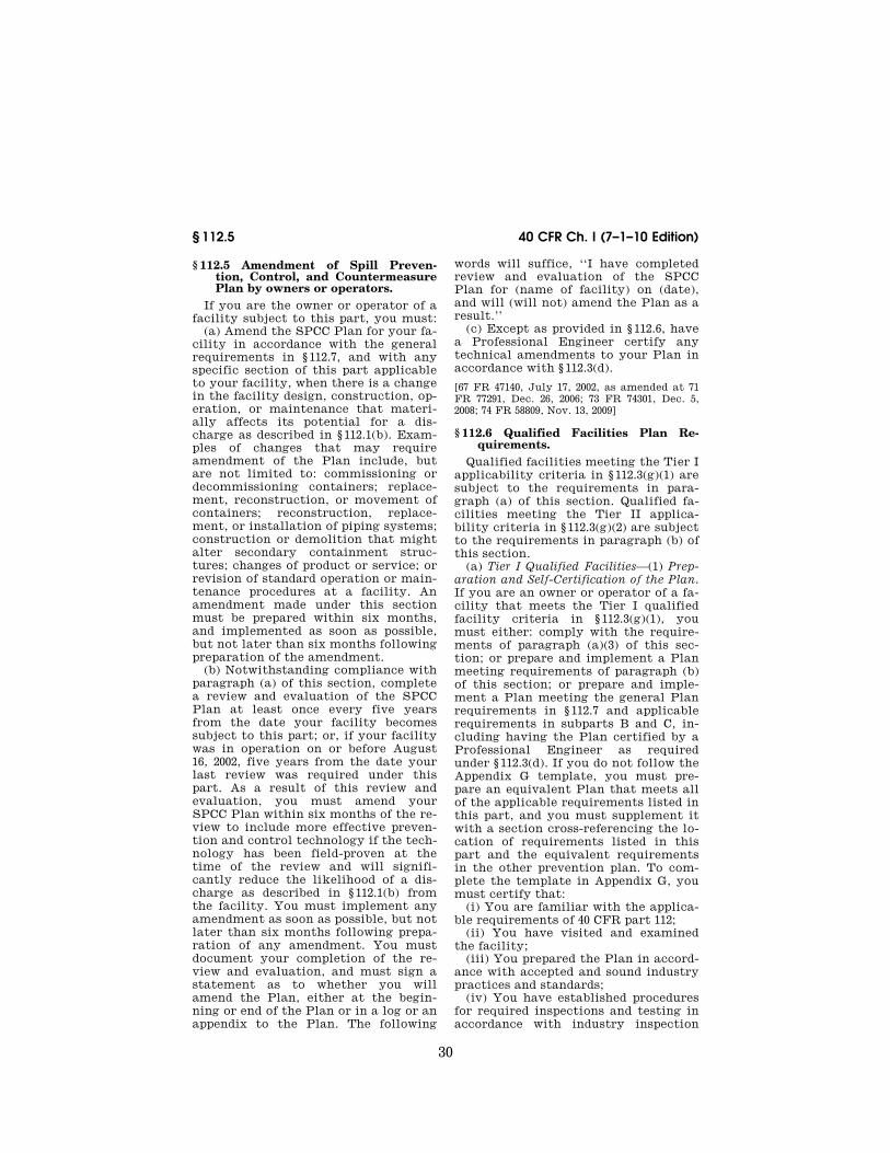
30
40 CFR Ch. I (7–1–10 Edition) § 112.5
§ 112.5 Amendment of Spill Preven-tion, Control, and Countermeasure Plan by owners or operators.
If you are the owner or operator of a facility subject to this part, you must:
(a) Amend the SPCC Plan for your fa-cility in accordance with the general requirements in § 112.7, and with any specific section of this part applicable to your facility, when there is a change in the facility design, construction, op-eration, or maintenance that materi-ally affects its potential for a dis-charge as described in § 112.1(b). Exam-ples of changes that may require amendment of the Plan include, but are not limited to: commissioning or decommissioning containers; replace-ment, reconstruction, or movement of containers; reconstruction, replace-ment, or installation of piping systems; construction or demolition that might alter secondary containment struc-tures; changes of product or service; or revision of standard operation or main-tenance procedures at a facility. An amendment made under this section must be prepared within six months, and implemented as soon as possible, but not later than six months following preparation of the amendment.
(b) Notwithstanding compliance with paragraph (a) of this section, complete a review and evaluation of the SPCC Plan at least once every five years from the date your facility becomes subject to this part; or, if your facility was in operation on or before August 16, 2002, five years from the date your last review was required under this part. As a result of this review and evaluation, you must amend your SPCC Plan within six months of the re-view to include more effective preven-tion and control technology if the tech-nology has been field-proven at the time of the review and will signifi-cantly reduce the likelihood of a dis-charge as described in § 112.1(b) from the facility. You must implement any amendment as soon as possible, but not later than six months following prepa-ration of any amendment. You must document your completion of the re-view and evaluation, and must sign a statement as to whether you will amend the Plan, either at the begin-ning or end of the Plan or in a log or an appendix to the Plan. The following
words will suffice, ‘‘I have completed review and evaluation of the SPCC Plan for (name of facility) on (date), and will (will not) amend the Plan as a result.’’
(c) Except as provided in § 112.6, have a Professional Engineer certify any technical amendments to your Plan in accordance with § 112.3(d).
[67 FR 47140, July 17, 2002, as amended at 71 FR 77291, Dec. 26, 2006; 73 FR 74301, Dec. 5, 2008; 74 FR 58809, Nov. 13, 2009]
§ 112.6 Qualified Facilities Plan Re-quirements.
Qualified facilities meeting the Tier I applicability criteria in § 112.3(g)(1) are subject to the requirements in para-graph (a) of this section. Qualified fa-cilities meeting the Tier II applica-bility criteria in § 112.3(g)(2) are subject to the requirements in paragraph (b) of this section.
(a) Tier I Qualified Facilities—(1) Prep-aration and Self-Certification of the Plan. If you are an owner or operator of a fa-cility that meets the Tier I qualified facility criteria in § 112.3(g)(1), you must either: comply with the require-ments of paragraph (a)(3) of this sec-tion; or prepare and implement a Plan meeting requirements of paragraph (b) of this section; or prepare and imple-ment a Plan meeting the general Plan requirements in § 112.7 and applicable requirements in subparts B and C, in-cluding having the Plan certified by a Professional Engineer as required under § 112.3(d). If you do not follow the Appendix G template, you must pre-pare an equivalent Plan that meets all of the applicable requirements listed in this part, and you must supplement it with a section cross-referencing the lo-cation of requirements listed in this part and the equivalent requirements in the other prevention plan. To com-plete the template in Appendix G, you must certify that:
(i) You are familiar with the applica-ble requirements of 40 CFR part 112;
(ii) You have visited and examined the facility;
(iii) You prepared the Plan in accord-ance with accepted and sound industry practices and standards;
(iv) You have established procedures for required inspections and testing in accordance with industry inspection
VerDate Mar<15>2010 08:15 Aug 05, 2010 Jkt 220163 PO 00000 Frm 00040 Fmt 8010 Sfmt 8010 Y:\SGML\220163.XXX 220163erow
e on
DS
K5C
LS3C
1PR
OD
with
CF
R

31
Environmental Protection Agency § 112.6
and testing standards or recommended practices;
(v) You will fully implement the Plan;
(vi) The facility meets the qualifica-tion criteria in § 112.3(g)(1);
(vii) The Plan does not deviate from any requirement of this part as allowed by § 112.7(a)(2) and 112.7(d) or include measures pursuant to § 112.9(c)(6) for produced water containers and any as-sociated piping; and
(viii) The Plan and individual(s) re-sponsible for implementing this Plan have the approval of management, and the facility owner or operator has com-mitted the necessary resources to fully implement this Plan.
(2) Technical Amendments. You must certify any technical amendments to your Plan in accordance with para-graph (a)(1) of this section when there is a change in the facility design, con-struction, operation, or maintenance that affects its potential for a dis-charge as described in § 112.1(b). If the facility change results in the facility no longer meeting the Tier I qualifying criteria in § 112.3(g)(1) because an indi-vidual oil storage container capacity exceeds 5,000 U.S. gallons or the facil-ity capacity exceeds 10,000 U.S. gallons in aggregate aboveground storage ca-pacity, within six months following preparation of the amendment, you must either:
(i) Prepare and implement a Plan in accordance with § 112.6(b) if you meet the Tier II qualified facility criteria in § 112.3(g)(2); or
(ii) Prepare and implement a Plan in accordance with the general Plan re-quirements in § 112.7, and applicable re-quirements in subparts B and C, includ-ing having the Plan certified by a Pro-fessional Engineer as required under § 112.3(d).
(3) Plan Template and Applicable Re-quirements. Prepare and implement an SPCC Plan that meets the following re-quirements under § 112.7 and in sub-parts B and C of this part: introductory paragraph of §§ 112.7, 112.7(a)(3)(i), 112.7(a)(3)(iv), 112.7(a)(3)(vi), 112.7(a)(4), 112.7(a)(5), 112.7(c), 112.7(e), 112.7(f), 112.7(g), 112.7(k), 112.8(b)(1), 112.8(b)(2), 112.8(c)(1), 112.8(c)(3), 112.8(c)(4), 112.8(c)(5), 112.8(c)(6), 112.8(c)(10), 112.8(d)(4), 112.9(b), 112.9(c)(1),
112.9(c)(2), 112.9(c)(3), 112.9(c)(4), 112.9(c)(5), 112.9(d)(1), 112.9(d)(3), 112.9(d)(4), 112.10(b), 112.10(c), 112.10(d), 112.12(b)(1), 112.12(b)(2), 112.12(c)(1), 112.12(c)(3), 112.12(c)(4), 112.12(c)(5), 112.12(c)(6), 112.12(c)(10), and 112.12(d)(4). The template in Appendix G to this part has been developed to meet the re-quirements of 40 CFR part 112 and, when completed and signed by the owner or operator, may be used as the SPCC Plan. Additionally, you must meet the following requirements:
(i) Failure analysis, in lieu of the re-quirements in § 112.7(b). Where experi-ence indicates a reasonable potential for equipment failure (such as loading or unloading equipment, tank overflow, rupture, or leakage, or any other equipment known to be a source of dis-charge), include in your Plan a pre-diction of the direction and total quan-tity of oil which could be discharged from the facility as a result of each type of major equipment failure.
(ii) Bulk storage container secondary containment, in lieu of the requirements in §§ 112.8(c)(2) and (c)(11) and 112.12(c)(2) and (c)(11). Construct all bulk storage container installations (except mobile refuelers and other non- transportation-related tank trucks), including mobile or portable oil stor-age containers, so that you provide a secondary means of containment for the entire capacity of the largest single container plus additional capacity to contain precipitation. Dikes, contain-ment curbs, and pits are commonly em-ployed for this purpose. You may also use an alternative system consisting of a drainage trench enclosure that must be arranged so that any discharge will terminate and be safely confined in a catchment basin or holding pond. Posi-tion or locate mobile or portable oil storage containers to prevent a dis-charge as described in § 112.1(b).
(iii) Overfill prevention, in lieu of the requirements in §§ 112.8(c)(8) and 112.12(c)(8). Ensure that each container is provided with a system or docu-mented procedure to prevent overfills of the container, describe the system or procedure in the SPCC Plan and reg-ularly test to ensure proper operation or efficacy.
(b) Tier II Qualified Facilities—(1) Preparation and Self-Certification of
VerDate Mar<15>2010 08:15 Aug 05, 2010 Jkt 220163 PO 00000 Frm 00041 Fmt 8010 Sfmt 8010 Y:\SGML\220163.XXX 220163erow
e on
DS
K5C
LS3C
1PR
OD
with
CF
R
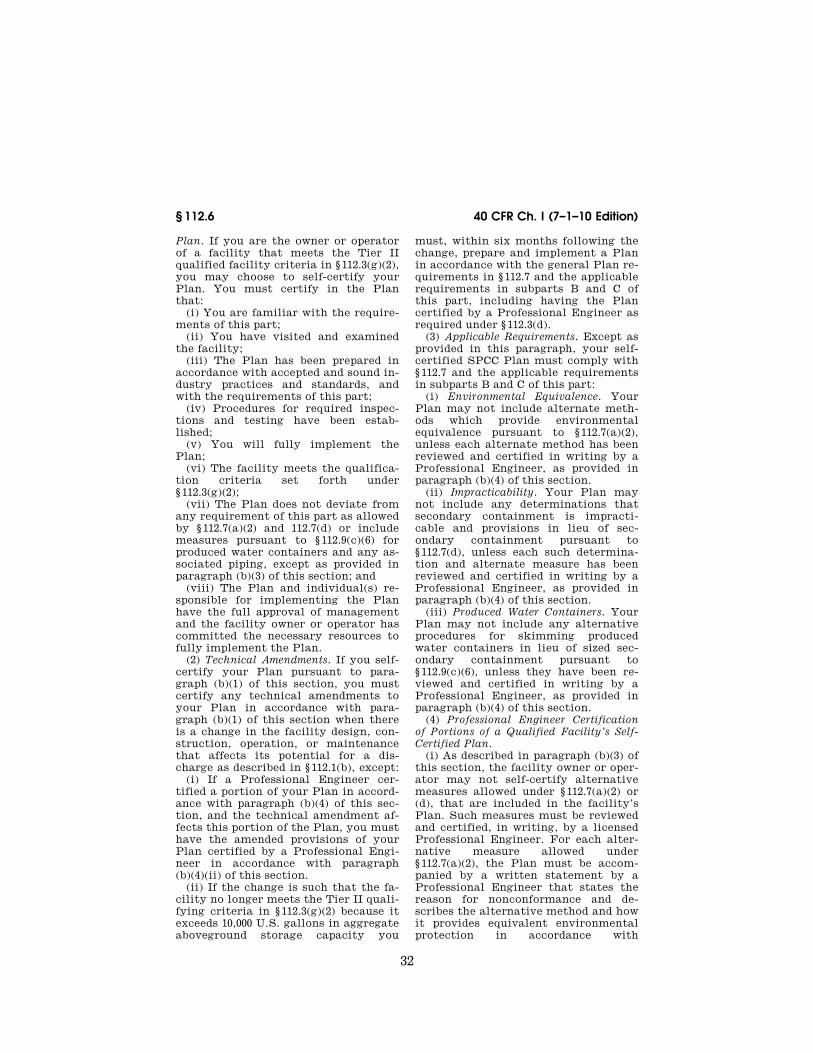
32
40 CFR Ch. I (7–1–10 Edition) § 112.6
Plan. If you are the owner or operator of a facility that meets the Tier II qualified facility criteria in § 112.3(g)(2), you may choose to self-certify your Plan. You must certify in the Plan that:
(i) You are familiar with the require-ments of this part;
(ii) You have visited and examined the facility;
(iii) The Plan has been prepared in accordance with accepted and sound in-dustry practices and standards, and with the requirements of this part;
(iv) Procedures for required inspec-tions and testing have been estab-lished;
(v) You will fully implement the Plan;
(vi) The facility meets the qualifica-tion criteria set forth under § 112.3(g)(2);
(vii) The Plan does not deviate from any requirement of this part as allowed by § 112.7(a)(2) and 112.7(d) or include measures pursuant to § 112.9(c)(6) for produced water containers and any as-sociated piping, except as provided in paragraph (b)(3) of this section; and
(viii) The Plan and individual(s) re-sponsible for implementing the Plan have the full approval of management and the facility owner or operator has committed the necessary resources to fully implement the Plan.
(2) Technical Amendments. If you self- certify your Plan pursuant to para-graph (b)(1) of this section, you must certify any technical amendments to your Plan in accordance with para-graph (b)(1) of this section when there is a change in the facility design, con-struction, operation, or maintenance that affects its potential for a dis-charge as described in § 112.1(b), except:
(i) If a Professional Engineer cer-tified a portion of your Plan in accord-ance with paragraph (b)(4) of this sec-tion, and the technical amendment af-fects this portion of the Plan, you must have the amended provisions of your Plan certified by a Professional Engi-neer in accordance with paragraph (b)(4)(ii) of this section.
(ii) If the change is such that the fa-cility no longer meets the Tier II quali-fying criteria in § 112.3(g)(2) because it exceeds 10,000 U.S. gallons in aggregate aboveground storage capacity you
must, within six months following the change, prepare and implement a Plan in accordance with the general Plan re-quirements in § 112.7 and the applicable requirements in subparts B and C of this part, including having the Plan certified by a Professional Engineer as required under § 112.3(d).
(3) Applicable Requirements. Except as provided in this paragraph, your self- certified SPCC Plan must comply with § 112.7 and the applicable requirements in subparts B and C of this part:
(i) Environmental Equivalence. Your Plan may not include alternate meth-ods which provide environmental equivalence pursuant to § 112.7(a)(2), unless each alternate method has been reviewed and certified in writing by a Professional Engineer, as provided in paragraph (b)(4) of this section.
(ii) Impracticability. Your Plan may not include any determinations that secondary containment is impracti-cable and provisions in lieu of sec-ondary containment pursuant to § 112.7(d), unless each such determina-tion and alternate measure has been reviewed and certified in writing by a Professional Engineer, as provided in paragraph (b)(4) of this section.
(iii) Produced Water Containers. Your Plan may not include any alternative procedures for skimming produced water containers in lieu of sized sec-ondary containment pursuant to § 112.9(c)(6), unless they have been re-viewed and certified in writing by a Professional Engineer, as provided in paragraph (b)(4) of this section.
(4) Professional Engineer Certification of Portions of a Qualified Facility’s Self- Certified Plan.
(i) As described in paragraph (b)(3) of this section, the facility owner or oper-ator may not self-certify alternative measures allowed under § 112.7(a)(2) or (d), that are included in the facility’s Plan. Such measures must be reviewed and certified, in writing, by a licensed Professional Engineer. For each alter-native measure allowed under § 112.7(a)(2), the Plan must be accom-panied by a written statement by a Professional Engineer that states the reason for nonconformance and de-scribes the alternative method and how it provides equivalent environmental protection in accordance with
VerDate Mar<15>2010 08:15 Aug 05, 2010 Jkt 220163 PO 00000 Frm 00042 Fmt 8010 Sfmt 8010 Y:\SGML\220163.XXX 220163erow
e on
DS
K5C
LS3C
1PR
OD
with
CF
R

33
Environmental Protection Agency § 112.7
§ 112.7(a)(2). For each determination of impracticability of secondary contain-ment pursuant to § 112.7(d), the Plan must clearly explain why secondary containment measures are not prac-ticable at this facility and provide the alternative measures required in § 112.7(d) in lieu of secondary contain-ment. By certifying each measure al-lowed under § 112.7(a)(2) and (d), the Professional Engineer attests:
(A) That he is familiar with the re-quirements of this part;
(B) That he or his agent has visited and examined the facility; and
(C) That the alternative method of environmental equivalence in accord-ance with § 112.7(a)(2) or the determina-tion of impracticability and alter-native measures in accordance with § 112.7(d) is consistent with good engi-neering practice, including consider-ation of applicable industry standards, and with the requirements of this part.
(ii) As described in paragraph (b)(3) of this section, the facility owner or oper-ator may not self-certify measures as described in § 112.9(c)(6) for produced water containers and any associated piping. Such measures must be re-viewed and certified, in writing, by a li-censed Professional Engineer, in ac-cordance with § 112.3(d)(1)(vi).
(iii) The review and certification by the Professional Engineer under this paragraph is limited to the alternative method which achieves equivalent en-vironmental protection pursuant to § 112.7(a)(2); to the impracticability de-termination and measures in lieu of secondary containment pursuant to § 112.7(d); or the measures pursuant to § 112.9(c)(6) for produced water con-tainers and any associated piping and appurtenances downstream from the container.
[73 FR 74302, Dec. 5, 2008, as amended at 74 FR 58810, Nov. 13, 2009]
§ 112.7 General requirements for Spill Prevention, Control, and Counter-measure Plans.
If you are the owner or operator of a facility subject to this part you must prepare a Plan in accordance with good engineering practices. The Plan must have the full approval of management at a level of authority to commit the necessary resources to fully implement
the Plan. You must prepare the Plan in writing. If you do not follow the se-quence specified in this section for the Plan, you must prepare an equivalent Plan acceptable to the Regional Ad-ministrator that meets all of the appli-cable requirements listed in this part, and you must supplement it with a sec-tion cross-referencing the location of requirements listed in this part and the equivalent requirements in the other prevention plan. If the Plan calls for additional facilities or procedures, methods, or equipment not yet fully operational, you must discuss these items in separate paragraphs, and must explain separately the details of instal-lation and operational start-up. As de-tailed elsewhere in this section, you must also:
(a)(1) Include a discussion of your fa-cility’s conformance with the require-ments listed in this part.
(2) Comply with all applicable re-quirements listed in this part. Except as provided in § 112.6, your Plan may deviate from the requirements in para-graphs (g), (h)(2) and (3), and (i) of this section and the requirements in sub-parts B and C of this part, except the secondary containment requirements in paragraphs (c) and (h)(1) of this sec-tion, and §§ 112.8(c)(2), 112.8(c)(11), 112.9(c)(2), 112.9(d)(3), 112.10(c), 112.12(c)(2), and 112.12(c)(11), where ap-plicable to a specific facility, if you provide equivalent environmental pro-tection by some other means of spill prevention, control, or counter-measure. Where your Plan does not conform to the applicable requirements in paragraphs (g), (h)(2) and (3), and (i) of this section, or the requirements of subparts B and C of this part, except the secondary containment require-ments in paragraph (c) and (h)(1) of this section, and §§ 112.8(c)(2), 112.8(c)(11), 112.9(c)(2), 112.10(c), 112.12(c)(2), and 112.12(c)(11), you must state the reasons for nonconformance in your Plan and describe in detail al-ternate methods and how you will achieve equivalent environmental pro-tection. If the Regional Administrator determines that the measures de-scribed in your Plan do not provide equivalent environmental protection, he may require that you amend your
VerDate Mar<15>2010 08:15 Aug 05, 2010 Jkt 220163 PO 00000 Frm 00043 Fmt 8010 Sfmt 8010 Y:\SGML\220163.XXX 220163erow
e on
DS
K5C
LS3C
1PR
OD
with
CF
R
34
40 CFR Ch. I (7–1–10 Edition) § 112.7
Plan, following the procedures in § 112.4(d) and (e).
(3) Describe in your Plan the physical layout of the facility and include a fa-cility diagram, which must mark the location and contents of each fixed oil storage container and the storage area where mobile or portable containers are located. The facility diagram must identify the location of and mark as ‘‘exempt’’ underground tanks that are otherwise exempted from the require-ments of this part under § 112.1(d)(4). The facility diagram must also include all transfer stations and connecting pipes, including intra-facility gath-ering lines that are otherwise exempt-ed from the requirements of this part under § 112.1(d)(11). You must also ad-dress in your Plan:
(i) The type of oil in each fixed con-tainer and its storage capacity. For mobile or portable containers, either provide the type of oil and storage ca-pacity for each container or provide an estimate of the potential number of mobile or portable containers, the types of oil, and anticipated storage ca-pacities;
(ii) Discharge prevention measures including procedures for routine han-dling of products (loading, unloading, and facility transfers, etc.);
(iii) Discharge or drainage controls such as secondary containment around containers and other structures, equip-ment, and procedures for the control of a discharge;
(iv) Countermeasures for discharge discovery, response, and cleanup (both the facility’s capability and those that might be required of a contractor);
(v) Methods of disposal of recovered materials in accordance with applica-ble legal requirements; and
(vi) Contact list and phone numbers for the facility response coordinator, National Response Center, cleanup con-tractors with whom you have an agree-ment for response, and all appropriate Federal, State, and local agencies who must be contacted in case of a dis-charge as described in § 112.1(b).
(4) Unless you have submitted a re-sponse plan under § 112.20, provide in-formation and procedures in your Plan to enable a person reporting a dis-charge as described in § 112.1(b) to re-late information on the exact address
or location and phone number of the fa-cility; the date and time of the dis-charge, the type of material dis-charged; estimates of the total quan-tity discharged; estimates of the quan-tity discharged as described in § 112.1(b); the source of the discharge; a description of all affected media; the cause of the discharge; any damages or injuries caused by the discharge; ac-tions being used to stop, remove, and mitigate the effects of the discharge; whether an evacuation may be needed; and, the names of individuals and/or or-ganizations who have also been con-tacted.
(5) Unless you have submitted a re-sponse plan under § 112.20, organize por-tions of the Plan describing procedures you will use when a discharge occurs in a way that will make them readily usa-ble in an emergency, and include ap-propriate supporting material as ap-pendices.
(b) Where experience indicates a rea-sonable potential for equipment failure (such as loading or unloading equip-ment, tank overflow, rupture, or leak-age, or any other equipment known to be a source of a discharge), include in your Plan a prediction of the direction, rate of flow, and total quantity of oil which could be discharged from the fa-cility as a result of each type of major equipment failure.
(c) Provide appropriate containment and/or diversionary structures or equipment to prevent a discharge as described in § 112.1(b), except as pro-vided in paragraph (k) of this section for qualified oil-filled operational equipment, and except as provided in § 112.9(d)(3) for flowlines and intra-facil-ity gathering lines at an oil production facility. The entire containment sys-tem, including walls and floor, must be capable of containing oil and must be constructed so that any discharge from a primary containment system, such as a tank, will not escape the contain-ment system before cleanup occurs. In determining the method, design, and capacity for secondary containment, you need only to address the typical failure mode, and the most likely quan-tity of oil that would be discharged. Secondary containment may be either
VerDate Mar<15>2010 08:15 Aug 05, 2010 Jkt 220163 PO 00000 Frm 00044 Fmt 8010 Sfmt 8010 Y:\SGML\220163.XXX 220163erow
e on
DS
K5C
LS3C
1PR
OD
with
CF
R

35
Environmental Protection Agency § 112.7
active or passive in design. At a min-imum, you must use one of the fol-lowing prevention systems or its equiv-alent:
(1) For onshore facilities: (i) Dikes, berms, or retaining walls
sufficiently impervious to contain oil; (ii) Curbing or drip pans; (iii) Sumps and collection systems; (iv) Culverting, gutters, or other
drainage systems; (v) Weirs, booms, or other barriers; (vi) Spill diversion ponds; (vii) Retention ponds; or (viii) Sorbent materials. (2) For offshore facilities: (i) Curbing or drip pans; or (ii) Sumps and collection systems. (d) Provided your Plan is certified by
a licensed Professional Engineer under § 112.3(d), or, in the case of a qualified facility that meets the criteria in § 112.3(g), the relevant sections of your Plan are certified by a licensed Profes-sional Engineer under § 112.6(d), if you determine that the installation of any of the structures or pieces of equip-ment listed in paragraphs (c) and (h)(1) of this section, and §§ 112.8(c)(2), 112.8(c)(11), 112.9(c)(2), 112.10(c), 112.12(c)(2), and 112.12(c)(11) to prevent a discharge as described in § 112.1(b) from any onshore or offshore facility is not practicable, you must clearly ex-plain in your Plan why such measures are not practicable; for bulk storage containers, conduct both periodic in-tegrity testing of the containers and periodic integrity and leak testing of the valves and piping; and, unless you have submitted a response plan under § 112.20, provide in your Plan the fol-lowing:
(1) An oil spill contingency plan fol-lowing the provisions of part 109 of this chapter.
(2) A written commitment of man-power, equipment, and materials re-quired to expeditiously control and re-move any quantity of oil discharged that may be harmful.
(e) Inspections, tests, and records. Con-duct inspections and tests required by this part in accordance with written procedures that you or the certifying engineer develop for the facility. You must keep these written procedures and a record of the inspections and tests, signed by the appropriate super-
visor or inspector, with the SPCC Plan for a period of three years. Records of inspections and tests kept under usual and customary business practices will suffice for purposes of this paragraph.
(f) Personnel, training, and discharge prevention procedures. (1) At a min-imum, train your oil-handling per-sonnel in the operation and mainte-nance of equipment to prevent dis-charges; discharge procedure protocols; applicable pollution control laws, rules, and regulations; general facility operations; and, the contents of the fa-cility SPCC Plan.
(2) Designate a person at each appli-cable facility who is accountable for discharge prevention and who reports to facility management.
(3) Schedule and conduct discharge prevention briefings for your oil-han-dling personnel at least once a year to assure adequate understanding of the SPCC Plan for that facility. Such brief-ings must highlight and describe known discharges as described in § 112.1(b) or failures, malfunctioning components, and any recently devel-oped precautionary measures.
(g) Security (excluding oil production facilities). Describe in your Plan how you secure and control access to the oil handling, processing and storage areas; secure master flow and drain valves; prevent unauthorized access to starter controls on oil pumps; secure out-of- service and loading/unloading connec-tions of oil pipelines; and address the appropriateness of security lighting to both prevent acts of vandalism and as-sist in the discovery of oil discharges.
(h) Facility tank car and tank truck loading/unloading rack (excluding off-shore facilities).
(1) Where loading/unloading rack drainage does not flow into a catchment basin or treatment facility designed to handle discharges, use a quick drainage system for tank car or tank truck loading/unloading racks. You must design any containment sys-tem to hold at least the maximum ca-pacity of any single compartment of a tank car or tank truck loaded or un-loaded at the facility.
(2) Provide an interlocked warning light or physical barrier system, warn-ing signs, wheel chocks or vehicle
VerDate Mar<15>2010 08:15 Aug 05, 2010 Jkt 220163 PO 00000 Frm 00045 Fmt 8010 Sfmt 8010 Y:\SGML\220163.XXX 220163erow
e on
DS
K5C
LS3C
1PR
OD
with
CF
R

36
40 CFR Ch. I (7–1–10 Edition) § 112.8
brake interlock system in the area ad-jacent to a loading/unloading rack, to prevent vehicles from departing before complete disconnection of flexible or fixed oil transfer lines.
(3) Prior to filling and departure of any tank car or tank truck, closely in-spect for discharges the lowermost drain and all outlets of such vehicles, and if necessary, ensure that they are tightened, adjusted, or replaced to pre-vent liquid discharge while in transit.
(i) If a field-constructed aboveground container undergoes a repair, alter-ation, reconstruction, or a change in service that might affect the risk of a discharge or failure due to brittle frac-ture or other catastrophe, or has dis-charged oil or failed due to brittle frac-ture failure or other catastrophe, evaluate the container for risk of dis-charge or failure due to brittle fracture or other catastrophe, and as necessary, take appropriate action.
(j) In addition to the minimal preven-tion standards listed under this sec-tion, include in your Plan a complete discussion of conformance with the ap-plicable requirements and other effec-tive discharge prevention and contain-ment procedures listed in this part or any applicable more stringent State rules, regulations, and guidelines.
(k) Qualified Oil-filled Operational Equipment. The owner or operator of a facility with oil-filled operational equipment that meets the qualification criteria in paragraph (k)(1) of this sub- section may choose to implement for this qualified oil-filled operational equipment the alternate requirements as described in paragraph (k)(2) of this sub-section in lieu of general secondary containment required in paragraph (c) of this section.
(1) Qualification Criteria—Reportable Discharge History: The owner or oper-ator of a facility that has had no single discharge as described in § 112.1(b) from any oil-filled operational equipment exceeding 1,000 U.S. gallons or no two discharges as described in § 112.1(b) from any oil-filled operational equip-ment each exceeding 42 U.S. gallons within any twelve month period in the three years prior to the SPCC Plan cer-tification date, or since becoming sub-ject to this part if the facility has been in operation for less than three years
(other than oil discharges as described in § 112.1(b) that are the result of nat-ural disasters, acts of war or ter-rorism); and
(2) Alternative Requirements to General Secondary Containment. If secondary containment is not provided for quali-fied oil-filled operational equipment pursuant to paragraph (c) of this sec-tion, the owner or operator of a facility with qualified oil-filled operational equipment must:
(i) Establish and document the facil-ity procedures for inspections or a monitoring program to detect equip-ment failure and/or a discharge; and
(ii) Unless you have submitted a re-sponse plan under § 112.20, provide in your Plan the following:
(A) An oil spill contingency plan fol-lowing the provisions of part 109 of this chapter.
(B) A written commitment of man-power, equipment, and materials re-quired to expeditiously control and re-move any quantity of oil discharged that may be harmful.
[67 FR 47140, July 17, 2002, as amended at 71 FR 77292, Dec. 26, 2006; 73 FR 74303, Dec. 5, 2008; 74 FR 58810, Nov. 13, 2009]
Subpart B—Requirements for Pe-troleum Oils and Non-Petro-leum Oils, Except Animal Fats and Oils and Greases, and Fish and Marine Mammal Oils; and Vegetable Oils (Including Oils from Seeds, Nuts, Fruits, and Kernels)
SOURCE: 67 FR 47146, July 17, 2002, unless otherwise noted.
§ 112.8 Spill Prevention, Control, and Countermeasure Plan requirements for onshore facilities (excluding production facilities).
If you are the owner or operator of an onshore facility (excluding a produc-tion facility), you must:
(a) Meet the general requirements for the Plan listed under § 112.7, and the specific discharge prevention and con-tainment procedures listed in this sec-tion.
(b) Facility drainage. (1) Restrain drainage from diked storage areas by valves to prevent a discharge into the
VerDate Mar<15>2010 08:15 Aug 05, 2010 Jkt 220163 PO 00000 Frm 00046 Fmt 8010 Sfmt 8010 Y:\SGML\220163.XXX 220163erow
e on
DS
K5C
LS3C
1PR
OD
with
CF
R

37
Environmental Protection Agency § 112.8
drainage system or facility effluent treatment system, except where facil-ity systems are designed to control such discharge. You may empty diked areas by pumps or ejectors; however, you must manually activate these pumps or ejectors and must inspect the condition of the accumulation before starting, to ensure no oil will be dis-charged.
(2) Use valves of manual, open-and- closed design, for the drainage of diked areas. You may not use flapper-type drain valves to drain diked areas. If your facility drainage drains directly into a watercourse and not into an on- site wastewater treatment plant, you must inspect and may drain uncontaminated retained stormwater, as provided in paragraphs (c)(3)(ii), (iii), and (iv) of this section.
(3) Design facility drainage systems from undiked areas with a potential for a discharge (such as where piping is lo-cated outside containment walls or where tank truck discharges may occur outside the loading area) to flow into ponds, lagoons, or catchment basins de-signed to retain oil or return it to the facility. You must not locate catchment basins in areas subject to periodic flooding.
(4) If facility drainage is not engi-neered as in paragraph (b)(3) of this section, equip the final discharge of all ditches inside the facility with a diver-sion system that would, in the event of an uncontrolled discharge, retain oil in the facility.
(5) Where drainage waters are treated in more than one treatment unit and such treatment is continuous, and pump transfer is needed, provide two ‘‘lift’’ pumps and permanently install at least one of the pumps. Whatever techniques you use, you must engineer facility drainage systems to prevent a discharge as described in § 112.1(b) in case there is an equipment failure or human error at the facility.
(c) Bulk storage containers. (1) Not use a container for the storage of oil unless its material and construction are com-patible with the material stored and conditions of storage such as pressure and temperature.
(2) Construct all bulk storage tank installations (except mobile refuelers and other non-transportation-related
tank trucks) so that you provide a sec-ondary means of containment for the entire capacity of the largest single container and sufficient freeboard to contain precipitation. You must ensure that diked areas are sufficiently imper-vious to contain discharged oil. Dikes, containment curbs, and pits are com-monly employed for this purpose. You may also use an alternative system consisting of a drainage trench enclo-sure that must be arranged so that any discharge will terminate and be safely confined in a facility catchment basin or holding pond.
(3) Not allow drainage of uncontaminated rainwater from the diked area into a storm drain or dis-charge of an effluent into an open wa-tercourse, lake, or pond, bypassing the facility treatment system unless you:
(i) Normally keep the bypass valve sealed closed.
(ii) Inspect the retained rainwater to ensure that its presence will not cause a discharge as described in § 112.1(b).
(iii) Open the bypass valve and reseal it following drainage under responsible supervision; and
(iv) Keep adequate records of such events, for example, any records re-quired under permits issued in accord-ance with §§ 122.41(j)(2) and 122.41(m)(3) of this chapter.
(4) Protect any completely buried metallic storage tank installed on or after January 10, 1974 from corrosion by coatings or cathodic protection compatible with local soil conditions. You must regularly leak test such completely buried metallic storage tanks.
(5) Not use partially buried or bunkered metallic tanks for the stor-age of oil, unless you protect the bur-ied section of the tank from corrosion. You must protect partially buried and bunkered tanks from corrosion by coatings or cathodic protection com-patible with local soil conditions.
(6) Test or inspect each aboveground container for integrity on a regular schedule and whenever you make mate-rial repairs. You must determine, in accordance with industry standards, the appropriate qualifications for per-sonnel performing tests and inspec-tions, the frequency and type of testing
VerDate Mar<15>2010 08:15 Aug 05, 2010 Jkt 220163 PO 00000 Frm 00047 Fmt 8010 Sfmt 8010 Y:\SGML\220163.XXX 220163erow
e on
DS
K5C
LS3C
1PR
OD
with
CF
R

38
40 CFR Ch. I (7–1–10 Edition) § 112.8
and inspections, which take into ac-count container size, configuration, and design (such as containers that are: shop-built, field-erected, skid- mounted, elevated, equipped with a liner, double-walled, or partially bur-ied). Examples of these integrity tests include, but are not limited to: visual inspection, hydrostatic testing, radio-graphic testing, ultrasonic testing, acoustic emissions testing, or other systems of non-destructive testing. You must keep comparison records and you must also inspect the container’s supports and foundations. In addition, you must frequently inspect the out-side of the container for signs of dete-rioration, discharges, or accumulation of oil inside diked areas. Records of in-spections and tests kept under usual and customary business practices sat-isfy the recordkeeping requirements of this paragraph.
(7) Control leakage through defective internal heating coils by monitoring the steam return and exhaust lines for contamination from internal heating coils that discharge into an open wa-tercourse, or pass the steam return or exhaust lines through a settling tank, skimmer, or other separation or reten-tion system.
(8) Engineer or update each container installation in accordance with good engineering practice to avoid dis-charges. You must provide at least one of the following devices:
(i) High liquid level alarms with an audible or visual signal at a constantly attended operation or surveillance sta-tion. In smaller facilities an audible air vent may suffice.
(ii) High liquid level pump cutoff de-vices set to stop flow at a predeter-mined container content level.
(iii) Direct audible or code signal communication between the container gauger and the pumping station.
(iv) A fast response system for deter-mining the liquid level of each bulk storage container such as digital com-puters, telepulse, or direct vision gauges. If you use this alternative, a person must be present to monitor gauges and the overall filling of bulk storage containers.
(v) You must regularly test liquid level sensing devices to ensure proper operation.
(9) Observe effluent treatment facili-ties frequently enough to detect pos-sible system upsets that could cause a discharge as described in § 112.1(b).
(10) Promptly correct visible dis-charges which result in a loss of oil from the container, including but not limited to seams, gaskets, piping, pumps, valves, rivets, and bolts. You must promptly remove any accumula-tions of oil in diked areas.
(11) Position or locate mobile or port-able oil storage containers to prevent a discharge as described in § 112.1(b). Ex-cept for mobile refuelers and other non-transportation-related tank trucks, you must furnish a secondary means of containment, such as a dike or catchment basin, sufficient to con-tain the capacity of the largest single compartment or container with suffi-cient freeboard to contain precipita-tion.
(d) Facility transfer operations, pump-ing, and facility process. (1) Provide bur-ied piping that is installed or replaced on or after August 16, 2002, with a pro-tective wrapping and coating. You must also cathodically protect such buried piping installations or otherwise satisfy the corrosion protection stand-ards for piping in part 280 of this chap-ter or a State program approved under part 281 of this chapter. If a section of buried line is exposed for any reason, you must carefully inspect it for dete-rioration. If you find corrosion damage, you must undertake additional exam-ination and corrective action as indi-cated by the magnitude of the damage.
(2) Cap or blank-flange the terminal connection at the transfer point and mark it as to origin when piping is not in service or is in standby service for an extended time.
(3) Properly design pipe supports to minimize abrasion and corrosion and allow for expansion and contraction.
(4) Regularly inspect all aboveground valves, piping, and appurtenances. Dur-ing the inspection you must assess the general condition of items, such as flange joints, expansion joints, valve glands and bodies, catch pans, pipeline supports, locking of valves, and metal surfaces. You must also conduct integ-rity and leak testing of buried piping
VerDate Mar<15>2010 08:15 Aug 05, 2010 Jkt 220163 PO 00000 Frm 00048 Fmt 8010 Sfmt 8010 Y:\SGML\220163.XXX 220163erow
e on
DS
K5C
LS3C
1PR
OD
with
CF
R

39
Environmental Protection Agency § 112.9
at the time of installation, modifica-tion, construction, relocation, or re-placement.
(5) Warn all vehicles entering the fa-cility to be sure that no vehicle will endanger aboveground piping or other oil transfer operations.
[67 FR 47146, July 17, 2002, as amended at 71 FR 77293, Dec. 26, 2006; 73 FR 74304, Dec. 5, 2008]
§ 112.9 Spill Prevention, Control, and Countermeasure Plan Require-ments for onshore oil production fa-cilities (excluding drilling and workover facilities).
If you are the owner or operator of an onshore oil production facility (exclud-ing a drilling or workover facility), you must:
(a) Meet the general requirements for the Plan listed under § 112.7, and the specific discharge prevention and con-tainment procedures listed under this section.
(b) Oil production facility drainage. (1) At tank batteries and separation and treating areas where there is a reason-able possibility of a discharge as de-scribed in § 112.1(b), close and seal at all times drains of dikes or drains of equivalent measures required under § 112.7(c)(1), except when draining uncontaminated rainwater. Prior to drainage, you must inspect the diked area and take action as provided in § 112.8(c)(3)(ii), (iii), and (iv). You must remove accumulated oil on the rain-water and return it to storage or dis-pose of it in accordance with legally approved methods.
(2) Inspect at regularly scheduled in-tervals field drainage systems (such as drainage ditches or road ditches), and oil traps, sumps, or skimmers, for an accumulation of oil that may have re-sulted from any small discharge. You must promptly remove any accumula-tions of oil.
(c) Oil production facility bulk storage containers. (1) Not use a container for the storage of oil unless its material and construction are compatible with the material stored and the conditions of storage.
(2) Except as described in paragraph (c)(5) of this section for flow-through process vessels and paragraph (c)(6) of this section for produced water con-
tainers and any associated piping and appurtenances downstream from the container, construct all tank battery, separation, and treating facility instal-lations, so that you provide a sec-ondary means of containment for the entire capacity of the largest single container and sufficient freeboard to contain precipitation. You must safely confine drainage from undiked areas in a catchment basin or holding pond.
(3) Except as described in paragraph (c)(5) of this section for flow-through process vessels and paragraph (c)(6) of this section for produced water con-tainers and any associated piping and appurtenances downstream from the container, periodically and upon a reg-ular schedule visually inspect each container of oil for deterioration and maintenance needs, including the foun-dation and support of each container that is on or above the surface of the ground.
(4) Engineer or update new and old tank battery installations in accord-ance with good engineering practice to prevent discharges. You must provide at least one of the following:
(i) Container capacity adequate to as-sure that a container will not overfill if a pumper/gauger is delayed in making regularly scheduled rounds.
(ii) Overflow equalizing lines between containers so that a full container can overflow to an adjacent container.
(iii) Vacuum protection adequate to prevent container collapse during a pipeline run or other transfer of oil from the container.
(iv) High level sensors to generate and transmit an alarm signal to the computer where the facility is subject to a computer production control sys-tem.
(5) Flow-through process vessels. The owner or operator of a facility with flow-through process vessels may choose to implement the alternate re-quirements as described below in lieu of sized secondary containment re-quired in paragraphs (c)(2) and (c)(3) of this section.
(i) Periodically and on a regular schedule visually inspect and/or test flow-through process vessels and asso-ciated components (such as dump valves) for leaks, corrosion, or other
VerDate Mar<15>2010 08:15 Aug 05, 2010 Jkt 220163 PO 00000 Frm 00049 Fmt 8010 Sfmt 8010 Y:\SGML\220163.XXX 220163erow
e on
DS
K5C
LS3C
1PR
OD
with
CF
R

40
40 CFR Ch. I (7–1–10 Edition) § 112.9
conditions that could lead to a dis-charge as described in § 112.1(b).
(ii) Take corrective action or make repairs to flow-through process vessels and any associated components as indi-cated by regularly scheduled visual in-spections, tests, or evidence of an oil discharge.
(iii) Promptly remove or initiate ac-tions to stabilize and remediate any ac-cumulations of oil discharges associ-ated with flow-through process vessels.
(iv) If your facility discharges more than 1,000 U.S. gallons of oil in a single discharge as described in § 112.1(b), or discharges more than 42 U.S. gallons of oil in each of two discharges as de-scribed in § 112.1(b) within any twelve month period, from flow-through proc-ess vessels (excluding discharges that are the result of natural disasters, acts of war, or terrorism) then you must, within six months from the time the facility becomes subject to this para-graph, ensure that all flow-through process vessels subject to this subpart comply with § 112.9(c)(2) and (c)(3).
(6) Produced water containers. For each produced water container, comply with § 112.9(c)(1) and (c)(4); and § 112.9(c)(2) and (c)(3), or comply with the provisions of the following para-graphs (c)(6)(i) through (v):
(i) Implement, on a regular schedule, a procedure for each produced water container that is designed to separate the free-phase oil that accumulates on the surface of the produced water. In-clude in the Plan a description of the procedures, frequency, amount of free- phase oil expected to be maintained in-side the container, and a Professional Engineer certification in accordance with § 112.3(d)(1)(vi). Maintain records of such events in accordance with § 112.7(e). Records kept under usual and customary business practices will suf-fice for purposes of this paragraph. If this procedure is not implemented as described in the Plan or no records are maintained, then you must comply with § 112.9(c)(2) and (c)(3).
(ii) On a regular schedule, visually inspect and/or test the produced water container and associated piping for leaks, corrosion, or other conditions that could lead to a discharge as de-scribed in § 112.1(b) in accordance with good engineering practice.
(iii) Take corrective action or make repairs to the produced water con-tainer and any associated piping as in-dicated by regularly scheduled visual inspections, tests, or evidence of an oil discharge.
(iv) Promptly remove or initiate ac-tions to stabilize and remediate any ac-cumulations of oil discharges associ-ated with the produced water con-tainer.
(v) If your facility discharges more than 1,000 U.S. gallons of oil in a single discharge as described in § 112.1(b), or discharges more than 42 U.S. gallons of oil in each of two discharges as de-scribed in § 112.1(b) within any twelve month period from a produced water container subject to this subpart (ex-cluding discharges that are the result of natural disasters, acts of war, or ter-rorism) then you must, within six months from the time the facility be-comes subject to this paragraph, en-sure that all produced water containers subject to this subpart comply with § 112.9(c)(2) and (c)(3).
(d) Facility transfer operations, oil pro-duction facility. (1) Periodically and upon a regular schedule inspect all aboveground valves and piping associ-ated with transfer operations for the general condition of flange joints, valve glands and bodies, drip pans, pipe supports, pumping well polish rod stuffing boxes, bleeder and gauge valves, and other such items.
(2) Inspect saltwater (oil field brine) disposal facilities often, particularly following a sudden change in atmos-pheric temperature, to detect possible system upsets capable of causing a dis-charge.
(3) For flowlines and intra-facility gathering lines that are not provided with secondary containment in accord-ance with § 112.7(c), unless you have submitted a response plan under § 112.20, provide in your Plan the fol-lowing:
(i) An oil spill contingency plan fol-lowing the provisions of part 109 of this chapter.
(ii) A written commitment of man-power, equipment, and materials re-quired to expeditiously control and re-move any quantity of oil discharged that might be harmful.
VerDate Mar<15>2010 08:15 Aug 05, 2010 Jkt 220163 PO 00000 Frm 00050 Fmt 8010 Sfmt 8010 Y:\SGML\220163.XXX 220163erow
e on
DS
K5C
LS3C
1PR
OD
with
CF
R

41
Environmental Protection Agency § 112.11
(4) Prepare and implement a written program of flowline/intra-facility gath-ering line maintenance. The mainte-nance program must address your pro-cedures to:
(i) Ensure that flowlines and intra-fa-cility gathering lines and associated valves and equipment are compatible with the type of production fluids, their potential corrosivity, volume, and pressure, and other conditions ex-pected in the operational environment.
(ii) Visually inspect and/or test flowlines and intra-facility gathering lines and associated appurtenances on a periodic and regular schedule for leaks, oil discharges, corrosion, or other conditions that could lead to a discharge as described in § 112.1(b). For flowlines and intra-facility gathering lines that are not provided with sec-ondary containment in accordance with § 112.7(c), the frequency and type of testing must allow for the imple-mentation of a contingency plan as de-scribed under part 109 of this chapter.
(iii) Take corrective action or make repairs to any flowlines and intra-facil-ity gathering lines and associated ap-purtenances as indicated by regularly scheduled visual inspections, tests, or evidence of a discharge.
(iv) Promptly remove or initiate ac-tions to stabilize and remediate any ac-cumulations of oil discharges associ-ated with flowlines, intra-facility gath-ering lines, and associated appur-tenances.
[73 FR, 74304, Dec. 5, 2008, as amended at 74 FR 58810, Nov. 13, 2009]
§ 112.10 Spill Prevention, Control, and Countermeasure Plan requirements for onshore oil drilling and workover facilities.
If you are the owner or operator of an onshore oil drilling and workover facil-ity, you must:
(a) Meet the general requirements listed under § 112.7, and also meet the specific discharge prevention and con-tainment procedures listed under this section.
(b) Position or locate mobile drilling or workover equipment so as to pre-vent a discharge as described in § 112.1(b).
(c) Provide catchment basins or di-version structures to intercept and
contain discharges of fuel, crude oil, or oily drilling fluids.
(d) Install a blowout prevention (BOP) assembly and well control sys-tem before drilling below any casing string or during workover operations. The BOP assembly and well control system must be capable of controlling any well-head pressure that may be en-countered while that BOP assembly and well control system are on the well.
§ 112.11 Spill Prevention, Control, and Countermeasure Plan requirements for offshore oil drilling, production, or workover facilities.
If you are the owner or operator of an offshore oil drilling, production, or workover facility, you must:
(a) Meet the general requirements listed under § 112.7, and also meet the specific discharge prevention and con-tainment procedures listed under this section.
(b) Use oil drainage collection equip-ment to prevent and control small oil discharges around pumps, glands, valves, flanges, expansion joints, hoses, drain lines, separators, treaters, tanks, and associated equipment. You must control and direct facility drains to-ward a central collection sump to pre-vent the facility from having a dis-charge as described in § 112.1(b). Where drains and sumps are not practicable, you must remove oil contained in col-lection equipment as often as nec-essary to prevent overflow.
(c) For facilities employing a sump system, provide adequately sized sump and drains and make available a spare pump to remove liquid from the sump and assure that oil does not escape. You must employ a regularly scheduled preventive maintenance inspection and testing program to assure reliable op-eration of the liquid removal system and pump start-up device. Redundant automatic sump pumps and control de-vices may be required on some installa-tions.
(d) At facilities with areas where sep-arators and treaters are equipped with dump valves which predominantly fail in the closed position and where pollu-tion risk is high, specially equip the fa-cility to prevent the discharge of oil.
VerDate Mar<15>2010 08:15 Aug 05, 2010 Jkt 220163 PO 00000 Frm 00051 Fmt 8010 Sfmt 8010 Y:\SGML\220163.XXX 220163erow
e on
DS
K5C
LS3C
1PR
OD
with
CF
R

42
40 CFR Ch. I (7–1–10 Edition) § 112.12
You must prevent the discharge of oil by:
(1) Extending the flare line to a diked area if the separator is near shore;
(2) Equipping the separator with a high liquid level sensor that will auto-matically shut in wells producing to the separator; or
(3) Installing parallel redundant dump valves.
(e) Equip atmospheric storage or surge containers with high liquid level sensing devices that activate an alarm or control the flow, or otherwise pre-vent discharges.
(f) Equip pressure containers with high and low pressure sensing devices that activate an alarm or control the flow.
(g) Equip containers with suitable corrosion protection.
(h) Prepare and maintain at the facil-ity a written procedure within the Plan for inspecting and testing pollution prevention equipment and systems.
(i) Conduct testing and inspection of the pollution prevention equipment and systems at the facility on a sched-uled periodic basis, commensurate with the complexity, conditions, and cir-cumstances of the facility and any other appropriate regulations. You must use simulated discharges for test-ing and inspecting human and equip-ment pollution control and counter-measure systems.
(j) Describe in detailed records sur-face and subsurface well shut-in valves and devices in use at the facility for each well sufficiently to determine their method of activation or control, such as pressure differential, change in fluid or flow conditions, combination of pressure and flow, manual or remote control mechanisms.
(k) Install a BOP assembly and well control system during workover oper-ations and before drilling below any casing string. The BOP assembly and well control system must be capable of controlling any well-head pressure that may be encountered while the BOP as-sembly and well control system are on the well.
(l) Equip all manifolds (headers) with check valves on individual flowlines.
(m) Equip the flowline with a high pressure sensing device and shut-in valve at the wellhead if the shut-in
well pressure is greater than the work-ing pressure of the flowline and mani-fold valves up to and including the header valves. Alternatively you may provide a pressure relief system for flowlines.
(n) Protect all piping appurtenant to the facility from corrosion, such as with protective coatings or cathodic protection.
(o) Adequately protect sub-marine piping appurtenant to the facility against environmental stresses and other activities such as fishing oper-ations.
(p) Maintain sub-marine piping ap-purtenant to the facility in good oper-ating condition at all times. You must periodically and according to a sched-ule inspect or test such piping for fail-ures. You must document and keep a record of such inspections or tests at the facility.
Subpart C—Requirements for Ani-mal Fats and Oils and Greases, and Fish and Marine Mammal Oils; and for Vege-table Oils, including Oils from Seeds, Nuts, Fruits, and Ker-nels.
SOURCE: 67 FR 57149, July 17, 2002, unless otherwise noted.
§ 112.12 Spill Prevention, Control, and Countermeasure Plan require-ments.
If you are the owner or operator of an onshore facility, you must:
(a) Meet the general requirements for the Plan listed under § 112.7, and the specific discharge prevention and con-tainment procedures listed in this sec-tion.
(b) Facility drainage. (1) Restrain drainage from diked storage areas by valves to prevent a discharge into the drainage system or facility effluent treatment system, except where facil-ity systems are designed to control such discharge. You may empty diked areas by pumps or ejectors; however, you must manually activate these pumps or ejectors and must inspect the condition of the accumulation before starting, to ensure no oil will be dis-charged.
VerDate Mar<15>2010 08:15 Aug 05, 2010 Jkt 220163 PO 00000 Frm 00052 Fmt 8010 Sfmt 8010 Y:\SGML\220163.XXX 220163erow
e on
DS
K5C
LS3C
1PR
OD
with
CF
R

43
Environmental Protection Agency § 112.12
(2) Use valves of manual, open-and- closed design, for the drainage of diked areas. You may not use flapper-type drain valves to drain diked areas. If your facility drainage drains directly into a watercourse and not into an on- site wastewater treatment plant, you must inspect and may drain uncontaminated retained stormwater, subject to the requirements of para-graphs (c)(3)(ii), (iii), and (iv) of this section.
(3) Design facility drainage systems from undiked areas with a potential for a discharge (such as where piping is lo-cated outside containment walls or where tank truck discharges may occur outside the loading area) to flow into ponds, lagoons, or catchment basins de-signed to retain oil or return it to the facility. You must not locate catchment basins in areas subject to periodic flooding.
(4) If facility drainage is not engi-neered as in paragraph (b)(3) of this section, equip the final discharge of all ditches inside the facility with a diver-sion system that would, in the event of an uncontrolled discharge, retain oil in the facility.
(5) Where drainage waters are treated in more than one treatment unit and such treatment is continuous, and pump transfer is needed, provide two ‘‘lift’’ pumps and permanently install at least one of the pumps. Whatever techniques you use, you must engineer facility drainage systems to prevent a discharge as described in § 112.1(b) in case there is an equipment failure or human error at the facility.
(c) Bulk storage containers. (1) Not use a container for the storage of oil unless its material and construction are com-patible with the material stored and conditions of storage such as pressure and temperature.
(2) Construct all bulk storage tank installations (except mobile refuelers and other non-transportation-related tank trucks) so that you provide a sec-ondary means of containment for the entire capacity of the largest single container and sufficient freeboard to contain precipitation. You must ensure that diked areas are sufficiently imper-vious to contain discharged oil. Dikes, containment curbs, and pits are com-monly employed for this purpose. You
may also use an alternative system consisting of a drainage trench enclo-sure that must be arranged so that any discharge will terminate and be safely confined in a facility catchment basin or holding pond.
(3) Not allow drainage of uncontaminated rainwater from the diked area into a storm drain or dis-charge of an effluent into an open wa-tercourse, lake, or pond, bypassing the facility treatment system unless you:
(i) Normally keep the bypass valve sealed closed.
(ii) Inspect the retained rainwater to ensure that its presence will not cause a discharge as described in § 112.1(b).
(iii) Open the bypass valve and reseal it following drainage under responsible supervision; and
(iv) Keep adequate records of such events, for example, any records re-quired under permits issued in accord-ance with §§ 122.41(j)(2) and 122.41(m)(3) of this chapter.
(4) Protect any completely buried metallic storage tank installed on or after January 10, 1974 from corrosion by coatings or cathodic protection compatible with local soil conditions. You must regularly leak test such completely buried metallic storage tanks.
(5) Not use partially buried or bunkered metallic tanks for the stor-age of oil, unless you protect the bur-ied section of the tank from corrosion. You must protect partially buried and bunkered tanks from corrosion by coatings or cathodic protection com-patible with local soil conditions.
(6) Bulk storage container inspections. (i) Except for containers that meet
the criteria provided in paragraph (c)(6)(ii) of this section, test or inspect each aboveground container for integ-rity on a regular schedule and when-ever you make material repairs. You must determine, in accordance with in-dustry standards, the appropriate qualifications for personnel performing tests and inspections, the frequency and type of testing and inspections, which take into account container size, configuration, and design (such as con-tainers that are: shop-built, field-erect-ed, skid-mounted, elevated, equipped with a liner, double-walled, or partially buried). Examples of these integrity
VerDate Mar<15>2010 08:15 Aug 05, 2010 Jkt 220163 PO 00000 Frm 00053 Fmt 8010 Sfmt 8010 Y:\SGML\220163.XXX 220163erow
e on
DS
K5C
LS3C
1PR
OD
with
CF
R
44
40 CFR Ch. I (7–1–10 Edition) § 112.12
tests include, but are not limited to: Visual inspection, hydrostatic testing, radiographic testing, ultrasonic test-ing, acoustic emissions testing, or other systems of non-destructive test-ing. You must keep comparison records and you must also inspect the con-tainer’s supports and foundations. In addition, you must frequently inspect the outside of the container for signs of deterioration, discharges, or accumula-tion of oil inside diked areas. Records of inspections and tests kept under usual and customary business practices satisfy the recordkeeping requirements of this paragraph.
(ii) For bulk storage containers that are subject to 21 CFR part 110, are ele-vated, constructed of austenitic stain-less steel, have no external insulation, and are shop-fabricated, conduct for-mal visual inspection on a regular schedule. In addition, you must fre-quently inspect the outside of the con-tainer for signs of deterioration, dis-charges, or accumulation of oil inside diked areas. You must determine and document in the Plan the appropriate qualifications for personnel performing tests and inspections. Records of in-spections and tests kept under usual and customary business practices sat-isfy the recordkeeping requirements of this paragraph (c)(6).
(7) Control leakage through defective internal heating coils by monitoring the steam return and exhaust lines for contamination from internal heating coils that discharge into an open wa-tercourse, or pass the steam return or exhaust lines through a settling tank, skimmer, or other separation or reten-tion system.
(8) Engineer or update each container installation in accordance with good engineering practice to avoid dis-charges. You must provide at least one of the following devices:
(i) High liquid level alarms with an audible or visual signal at a constantly attended operation or surveillance sta-tion. In smaller facilities an audible air vent may suffice.
(ii) High liquid level pump cutoff de-vices set to stop flow at a predeter-mined container content level.
(iii) Direct audible or code signal communication between the container gauger and the pumping station.
(iv) A fast response system for deter-mining the liquid level of each bulk storage container such as digital com-puters, telepulse, or direct vision gauges. If you use this alternative, a person must be present to monitor gauges and the overall filling of bulk storage containers.
(v) You must regularly test liquid level sensing devices to ensure proper operation.
(9) Observe effluent treatment facili-ties frequently enough to detect pos-sible system upsets that could cause a discharge as described in § 112.1(b).
(10) Promptly correct visible dis-charges which result in a loss of oil from the container, including but not limited to seams, gaskets, piping, pumps, valves, rivets, and bolts. You must promptly remove any accumula-tions of oil in diked areas.
(11) Position or locate mobile or port-able oil storage containers to prevent a discharge as described in § 112.1(b). Ex-cept for mobile refuelers and other non-transportation-related tank trucks, you must furnish a secondary means of containment, such as a dike or catchment basin, sufficient to con-tain the capacity of the largest single compartment or container with suffi-cient freeboard to contain precipita-tion.
(d) Facility transfer operations, pump-ing, and facility process. (1) Provide bur-ied piping that is installed or replaced on or after August 16, 2002, with a pro-tective wrapping and coating. You must also cathodically protect such buried piping installations or otherwise satisfy the corrosion protection stand-ards for piping in part 280 of this chap-ter or a State program approved under part 281 of this chapter. If a section of buried line is exposed for any reason, you must carefully inspect it for dete-rioration. If you find corrosion damage, you must undertake additional exam-ination and corrective action as indi-cated by the magnitude of the damage.
(2) Cap or blank-flange the terminal connection at the transfer point and mark it as to origin when piping is not in service or is in standby service for an extended time.
(3) Properly design pipe supports to minimize abrasion and corrosion and allow for expansion and contraction.
VerDate Mar<15>2010 08:15 Aug 05, 2010 Jkt 220163 PO 00000 Frm 00054 Fmt 8010 Sfmt 8010 Y:\SGML\220163.XXX 220163erow
e on
DS
K5C
LS3C
1PR
OD
with
CF
R

45
Environmental Protection Agency § 112.20
(4) Regularly inspect all aboveground valves, piping, and appurtenances. Dur-ing the inspection you must assess the general condition of items, such as flange joints, expansion joints, valve glands and bodies, catch pans, pipeline supports, locking of valves, and metal surfaces. You must also conduct integ-rity and leak testing of buried piping at the time of installation, modifica-tion, construction, relocation, or re-placement.
(5) Warn all vehicles entering the fa-cility to be sure that no vehicle will endanger aboveground piping or other oil transfer operations.
[67 FR 57149, July 17, 2002, as amended at 71 FR 77293, Dec. 26, 2006; 73 FR 74305, Dec. 5, 2008]
§§ 112.13–112.15 [Reserved]
Subpart D—Response Requirements
§ 112.20 Facility response plans. (a) The owner or operator of any non-
transportation-related onshore facility that, because of its location, could rea-sonably be expected to cause substan-tial harm to the environment by dis-charging oil into or on the navigable waters or adjoining shorelines shall prepare and submit a facility response plan to the Regional Administrator, according to the following provisions:
(1) For the owner or operator of a fa-cility in operation on or before Feb-ruary 18, 1993 who is required to pre-pare and submit a response plan under 33 U.S.C. 1321(j)(5), the Oil Pollution Act of 1990 (Pub. L. 101–380, 33 U.S.C. 2701 et seq.) requires the submission of a response plan that satisfies the re-quirements of 33 U.S.C. 1321(j)(5) no later than February 18, 1993.
(i) The owner or operator of an exist-ing facility that was in operation on or before February 18, 1993 who submitted a response plan by February 18, 1993 shall revise the response plan to satisfy the requirements of this section and re-submit the response plan or updated portions of the response plan to the Re-gional Administrator by February 18, 1995.
(ii) The owner or operator of an exist-ing facility in operation on or before February 18, 1993 who failed to submit
a response plan by February 18, 1993 shall prepare and submit a response plan that satisfies the requirements of this section to the Regional Adminis-trator before August 30, 1994.
(2) The owner or operator of a facility in operation on or after August 30, 1994 that satisfies the criteria in paragraph (f)(1) of this section or that is notified by the Regional Administrator pursu-ant to paragraph (b) of this section shall prepare and submit a facility re-sponse plan that satisfies the require-ments of this section to the Regional Administrator.
(i) For a facility that commenced op-erations after February 18, 1993 but prior to August 30, 1994, and is required to prepare and submit a response plan based on the criteria in paragraph (f)(1) of this section, the owner or operator shall submit the response plan or up-dated portions of the response plan, along with a completed version of the response plan cover sheet contained in appendix F to this part, to the Re-gional Administrator prior to August 30, 1994.
(ii) For a newly constructed facility that commences operation after Au-gust 30, 1994, and is required to prepare and submit a response plan based on the criteria in paragraph (f)(1) of this section, the owner or operator shall submit the response plan, along with a completed version of the response plan cover sheet contained in appendix F to this part, to the Regional Adminis-trator prior to the start of operations (adjustments to the response plan to reflect changes that occur at the facil-ity during the start-up phase of oper-ations must be submitted to the Re-gional Administrator after an oper-ational trial period of 60 days).
(iii) For a facility required to prepare and submit a response plan after Au-gust 30, 1994, as a result of a planned change in design, construction, oper-ation, or maintenance that renders the facility subject to the criteria in para-graph (f)(1) of this section, the owner or operator shall submit the response plan, along with a completed version of the response plan cover sheet con-tained in appendix F to this part, to the Regional Administrator before the portion of the facility undergoing
VerDate Mar<15>2010 08:15 Aug 05, 2010 Jkt 220163 PO 00000 Frm 00055 Fmt 8010 Sfmt 8010 Y:\SGML\220163.XXX 220163erow
e on
DS
K5C
LS3C
1PR
OD
with
CF
R

45
Environmental Protection Agency § 112.20
must promptly remove any accumula-tions of oil in diked areas.
(11) Position or locate mobile or port-able oil storage containers to prevent a discharge as described in § 112.1(b). Ex-cept for mobile refuelers and other non-transportation-related tank trucks, you must furnish a secondary means of containment, such as a dike or catchment basin, sufficient to con-tain the capacity of the largest single compartment or container with suffi-cient freeboard to contain precipita-tion.
(d) Facility transfer operations, pump-ing, and facility process. (1) Provide bur-ied piping that is installed or replaced on or after August 16, 2002, with a pro-tective wrapping and coating. You must also cathodically protect such buried piping installations or otherwise satisfy the corrosion protection stand-ards for piping in part 280 of this chap-ter or a State program approved under part 281 of this chapter. If a section of buried line is exposed for any reason, you must carefully inspect it for dete-rioration. If you find corrosion damage, you must undertake additional exam-ination and corrective action as indi-cated by the magnitude of the damage.
(2) Cap or blank-flange the terminal connection at the transfer point and mark it as to origin when piping is not in service or is in standby service for an extended time.
(3) Properly design pipe supports to minimize abrasion and corrosion and allow for expansion and contraction.
(4) Regularly inspect all aboveground valves, piping, and appurtenances. Dur-ing the inspection you must assess the general condition of items, such as flange joints, expansion joints, valve glands and bodies, catch pans, pipeline supports, locking of valves, and metal surfaces. You must also conduct integ-rity and leak testing of buried piping at the time of installation, modifica-tion, construction, relocation, or re-placement.
(5) Warn all vehicles entering the fa-cility to be sure that no vehicle will endanger aboveground piping or other oil transfer operations.
[67 FR 57149, July 17, 2002, as amended at 71 FR 77293, Dec. 26, 2006; 73 FR 74305, Dec. 5, 2008]
§§ 112.13–112.15 [Reserved]
Subpart D—Response Requirements
§ 112.20 Facility response plans. (a) The owner or operator of any non-
transportation-related onshore facility that, because of its location, could rea-sonably be expected to cause substan-tial harm to the environment by dis-charging oil into or on the navigable waters or adjoining shorelines shall prepare and submit a facility response plan to the Regional Administrator, according to the following provisions:
(1) For the owner or operator of a fa-cility in operation on or before Feb-ruary 18, 1993 who is required to pre-pare and submit a response plan under 33 U.S.C. 1321(j)(5), the Oil Pollution Act of 1990 (Pub. L. 101–380, 33 U.S.C. 2701 et seq.) requires the submission of a response plan that satisfies the re-quirements of 33 U.S.C. 1321(j)(5) no later than February 18, 1993.
(i) The owner or operator of an exist-ing facility that was in operation on or before February 18, 1993 who submitted a response plan by February 18, 1993 shall revise the response plan to satisfy the requirements of this section and re-submit the response plan or updated portions of the response plan to the Re-gional Administrator by February 18, 1995.
(ii) The owner or operator of an exist-ing facility in operation on or before February 18, 1993 who failed to submit a response plan by February 18, 1993 shall prepare and submit a response plan that satisfies the requirements of this section to the Regional Adminis-trator before August 30, 1994.
(2) The owner or operator of a facility in operation on or after August 30, 1994 that satisfies the criteria in paragraph (f)(1) of this section or that is notified by the Regional Administrator pursu-ant to paragraph (b) of this section shall prepare and submit a facility re-sponse plan that satisfies the require-ments of this section to the Regional Administrator.
(i) For a facility that commenced op-erations after February 18, 1993 but prior to August 30, 1994, and is required to prepare and submit a response plan based on the criteria in paragraph (f)(1)
VerDate Mar<15>2010 10:37 Jul 28, 2011 Jkt 223165 PO 00000 Frm 00055 Fmt 8010 Sfmt 8010 Y:\SGML\223165.XXX 223165wre
ier-
avile
s on
DS
KG
BLS
3C1P
RO
D w
ith C
FR

46
40 CFR Ch. I (7–1–11 Edition) § 112.20
of this section, the owner or operator shall submit the response plan or up-dated portions of the response plan, along with a completed version of the response plan cover sheet contained in appendix F to this part, to the Re-gional Administrator prior to August 30, 1994.
(ii) For a newly constructed facility that commences operation after Au-gust 30, 1994, and is required to prepare and submit a response plan based on the criteria in paragraph (f)(1) of this section, the owner or operator shall submit the response plan, along with a completed version of the response plan cover sheet contained in appendix F to this part, to the Regional Adminis-trator prior to the start of operations (adjustments to the response plan to reflect changes that occur at the facil-ity during the start-up phase of oper-ations must be submitted to the Re-gional Administrator after an oper-ational trial period of 60 days).
(iii) For a facility required to prepare and submit a response plan after Au-gust 30, 1994, as a result of a planned change in design, construction, oper-ation, or maintenance that renders the facility subject to the criteria in para-graph (f)(1) of this section, the owner or operator shall submit the response plan, along with a completed version of the response plan cover sheet con-tained in appendix F to this part, to the Regional Administrator before the portion of the facility undergoing change commences operations (adjust-ments to the response plan to reflect changes that occur at the facility dur-ing the start-up phase of operations must be submitted to the Regional Ad-ministrator after an operational trial period of 60 days).
(iv) For a facility required to prepare and submit a response plan after Au-gust 30, 1994, as a result of an un-planned event or change in facility characteristics that renders the facil-ity subject to the criteria in paragraph (f)(1) of this section, the owner or oper-ator shall submit the response plan, along with a completed version of the response plan cover sheet contained in appendix F to this part, to the Re-gional Administrator within six months of the unplanned event or change.
(3) In the event the owner or operator of a facility that is required to prepare and submit a response plan uses an al-ternative formula that is comparable to one contained in appendix C to this part to evaluate the criterion in para-graph (f)(1)(ii)(B) or (f)(1)(ii)(C) of this section, the owner or operator shall at-tach documentation to the response plan cover sheet contained in appendix F to this part that demonstrates the reliability and analytical soundness of the alternative formula.
(4) Preparation and submission of re-sponse plans—Animal fat and vegetable oil facilities. The owner or operator of any non-transportation-related facility that handles, stores, or transports ani-mal fats and vegetable oils must pre-pare and submit a facility response plan as follows:
(i) Facilities with approved plans. The owner or operator of a facility with a facility response plan that has been ap-proved under paragraph (c) of this sec-tion by July 31, 2000 need not prepare or submit a revised plan except as oth-erwise required by paragraphs (b), (c), or (d) of this section.
(ii) Facilities with plans that have been submitted to the Regional Administrator. Except for facilities with approved plans as provided in paragraph (a)(4)(i) of this section, the owner or operator of a facility that has submitted a re-sponse plan to the Regional Adminis-trator prior to July 31, 2000 must re-view the plan to determine if it meets or exceeds the applicable provisions of this part. An owner or operator need not prepare or submit a new plan if the existing plan meets or exceeds the ap-plicable provisions of this part. If the plan does not meet or exceed the appli-cable provisions of this part, the owner or operator must prepare and submit a new plan by September 28, 2000.
(iii) Newly regulated facilities. The owner or operator of a newly con-structed facility that commences oper-ation after July 31, 2000 must prepare and submit a plan to the Regional Ad-ministrator in accordance with para-graph (a)(2)(ii) of this section. The plan must meet or exceed the applicable provisions of this part. The owner or operator of an existing facility that must prepare and submit a plan after July 31, 2000 as a result of a planned or
VerDate Mar<15>2010 10:37 Jul 28, 2011 Jkt 223165 PO 00000 Frm 00056 Fmt 8010 Sfmt 8010 Y:\SGML\223165.XXX 223165wre
ier-
avile
s on
DS
KG
BLS
3C1P
RO
D w
ith C
FR

47
Environmental Protection Agency § 112.20
unplanned change in facility character-istics that causes the facility to be-come regulated under paragraph (f)(1) of this section, must prepare and sub-mit a plan to the Regional Adminis-trator in accordance with paragraph (a)(2)(iii) or (iv) of this section, as ap-propriate. The plan must meet or ex-ceed the applicable provisions of this part.
(iv) Facilities amending existing plans. The owner or operator of a facility sub-mitting an amended plan in accordance with paragraph (d) of this section after July 31, 2000, including plans that had been previously approved, must also re-view the plan to determine if it meets or exceeds the applicable provisions of this part. If the plan does not meet or exceed the applicable provisions of this part, the owner or operator must revise and resubmit revised portions of an amended plan to the Regional Adminis-trator in accordance with paragraph (d) of this section, as appropriate. The plan must meet or exceed the applica-ble provisions of this part.
(b)(1) The Regional Administrator may at any time require the owner or operator of any non-transportation-re-lated onshore facility to prepare and submit a facility response plan under this section after considering the fac-tors in paragraph (f)(2) of this section. If such a determination is made, the Regional Administrator shall notify the facility owner or operator in writ-ing and shall provide a basis for the de-termination. If the Regional Adminis-trator notifies the owner or operator in writing of the requirement to prepare and submit a response plan under this section, the owner or operator of the facility shall submit the response plan to the Regional Administrator within six months of receipt of such written notification.
(2) The Regional Administrator shall review plans submitted by such facili-ties to determine whether the facility could, because of its location, reason-ably be expected to cause significant and substantial harm to the environ-ment by discharging oil into or on the navigable waters or adjoining shore-lines.
(c) The Regional Administrator shall determine whether a facility could, be-cause of its location, reasonably be ex-
pected to cause significant and sub-stantial harm to the environment by discharging oil into or on the navigable waters or adjoining shorelines, based on the factors in paragraph (f)(3) of this section. If such a determination is made, the Regional Administrator shall notify the owner or operator of the facility in writing and:
(1) Promptly review the facility re-sponse plan;
(2) Require amendments to any re-sponse plan that does not meet the re-quirements of this section;
(3) Approve any response plan that meets the requirements of this section; and
(4) Review each response plan peri-odically thereafter on a schedule estab-lished by the Regional Administrator provided that the period between plan reviews does not exceed five years.
(d)(1) The owner or operator of a fa-cility for which a response plan is re-quired under this part shall revise and resubmit revised portions of the re-sponse plan within 60 days of each fa-cility change that materially may af-fect the response to a worst case dis-charge, including:
(i) A change in the facility’s configu-ration that materially alters the infor-mation included in the response plan;
(ii) A change in the type of oil han-dled, stored, or transferred that mate-rially alters the required response re-sources;
(iii) A material change in capabilities of the oil spill removal organization(s) that provide equipment and personnel to respond to discharges of oil de-scribed in paragraph (h)(5) of this sec-tion;
(iv) A material change in the facili-ty’s spill prevention and response equipment or emergency response pro-cedures; and
(v) Any other changes that materi-ally affect the implementation of the response plan.
(2) Except as provided in paragraph (d)(1) of this section, amendments to personnel and telephone number lists included in the response plan and a change in the oil spill removal organi-zation(s) that does not result in a ma-terial change in support capabilities do not require approval by the Regional
VerDate Mar<15>2010 10:37 Jul 28, 2011 Jkt 223165 PO 00000 Frm 00057 Fmt 8010 Sfmt 8010 Y:\SGML\223165.XXX 223165wre
ier-
avile
s on
DS
KG
BLS
3C1P
RO
D w
ith C
FR

48
40 CFR Ch. I (7–1–11 Edition) § 112.20
Administrator. Facility owners or op-erators shall provide a copy of such changes to the Regional Administrator as the revisions occur.
(3) The owner or operator of a facility that submits changes to a response plan as provided in paragraph (d)(1) or (d)(2) of this section shall provide the EPA-issued facility identification num-ber (where one has been assigned) with the changes.
(4) The Regional Administrator shall review for approval changes to a re-sponse plan submitted pursuant to paragraph (d)(1) of this section for a fa-cility determined pursuant to para-graph (f)(3) of this section to have the potential to cause significant and sub-stantial harm to the environment.
(e) If the owner or operator of a facil-ity determines pursuant to paragraph (a)(2) of this section that the facility could not, because of its location, rea-sonably be expected to cause substan-tial harm to the environment by dis-charging oil into or on the navigable waters or adjoining shorelines, the owner or operator shall complete and maintain at the facility the certifi-cation form contained in appendix C to this part and, in the event an alter-native formula that is comparable to one contained in appendix C to this part is used to evaluate the criterion in paragraph (f)(1)(ii)(B) or (f)(1)(ii)(C) of this section, the owner or operator shall attach documentation to the cer-tification form that demonstrates the reliability and analytical soundness of the comparable formula and shall no-tify the Regional Administrator in writing that an alternative formula was used.
(f)(1) A facility could, because of its location, reasonably be expected to cause substantial harm to the environ-ment by discharging oil into or on the navigable waters or adjoining shore-lines pursuant to paragraph (a)(2) of this section, if it meets any of the fol-lowing criteria applied in accordance with the flowchart contained in attach-ment C-I to appendix C to this part:
(i) The facility transfers oil over water to or from vessels and has a total oil storage capacity greater than or equal to 42,000 gallons; or
(ii) The facility’s total oil storage ca-pacity is greater than or equal to 1 mil-
lion gallons, and one of the following is true:
(A) The facility does not have sec-ondary containment for each above-ground storage area sufficiently large to contain the capacity of the largest aboveground oil storage tank within each storage area plus sufficient freeboard to allow for precipitation;
(B) The facility is located at a dis-tance (as calculated using the appro-priate formula in appendix C to this part or a comparable formula) such that a discharge from the facility could cause injury to fish and wildlife and sensitive environments. For further de-scription of fish and wildlife and sen-sitive environments, see Appendices I, II, and III of the ‘‘Guidance for Facility and Vessel Response Plans: Fish and Wildlife and Sensitive Environments’’ (see Appendix E to this part, section 13, for availability) and the applicable Area Contingency Plan prepared pursu-ant to section 311(j)(4) of the Clean Water Act;
(C) The facility is located at a dis-tance (as calculated using the appro-priate formula in appendix C to this part or a comparable formula) such that a discharge from the facility would shut down a public drinking water intake; or
(D) The facility has had a reportable oil discharge in an amount greater than or equal to 10,000 gallons within the last 5 years.
(2)(i) To determine whether a facility could, because of its location, reason-ably be expected to cause substantial harm to the environment by dis-charging oil into or on the navigable waters or adjoining shorelines pursu-ant to paragraph (b) of this section, the Regional Administrator shall consider the following:
(A) Type of transfer operation; (B) Oil storage capacity; (C) Lack of secondary containment; (D) Proximity to fish and wildlife and
sensitive environments and other areas determined by the Regional Adminis-trator to possess ecological value;
(E) Proximity to drinking water in-takes;
(F) Spill history; and (G) Other site-specific characteristics
and environmental factors that the Re-gional Administrator determines to be
VerDate Mar<15>2010 10:37 Jul 28, 2011 Jkt 223165 PO 00000 Frm 00058 Fmt 8010 Sfmt 8010 Y:\SGML\223165.XXX 223165wre
ier-
avile
s on
DS
KG
BLS
3C1P
RO
D w
ith C
FR

49
Environmental Protection Agency § 112.20
relevant to protecting the environment from harm by discharges of oil into or on navigable waters or adjoining shore-lines.
(ii) Any person, including a member of the public or any representative from a Federal, State, or local agency who believes that a facility subject to this section could, because of its loca-tion, reasonably be expected to cause substantial harm to the environment by discharging oil into or on the navi-gable waters or adjoining shorelines may petition the Regional Adminis-trator to determine whether the facil-ity meets the criteria in paragraph (f)(2)(i) of this section. Such petition shall include a discussion of how the factors in paragraph (f)(2)(i) of this sec-tion apply to the facility in question. The RA shall consider such petitions and respond in an appropriate amount of time.
(3) To determine whether a facility could, because of its location, reason-ably be expected to cause significant and substantial harm to the environ-ment by discharging oil into or on the navigable waters or adjoining shore-lines, the Regional Administrator may consider the factors in paragraph (f)(2) of this section as well as the following:
(i) Frequency of past discharges; (ii) Proximity to navigable waters; (iii) Age of oil storage tanks; and (iv) Other facility-specific and Re-
gion-specific information, including local impacts on public health.
(g)(1) All facility response plans shall be consistent with the requirements of the National Oil and Hazardous Sub-stance Pollution Contingency Plan (40 CFR part 300) and applicable Area Con-tingency Plans prepared pursuant to section 311(j)(4) of the Clean Water Act. The facility response plan should be co-ordinated with the local emergency re-sponse plan developed by the local emergency planning committee under section 303 of Title III of the Superfund Amendments and Reauthorization Act of 1986 (42 U.S.C. 11001 et seq.). Upon re-quest, the owner or operator should provide a copy of the facility response plan to the local emergency planning committee or State emergency re-sponse commission.
(2) The owner or operator shall re-view relevant portions of the National
Oil and Hazardous Substances Pollu-tion Contingency Plan and applicable Area Contingency Plan annually and, if necessary, revise the facility response plan to ensure consistency with these plans.
(3) The owner or operator shall re-view and update the facility response plan periodically to reflect changes at the facility.
(h) A response plan shall follow the format of the model facility-specific re-sponse plan included in appendix F to this part, unless you have prepared an equivalent response plan acceptable to the Regional Administrator to meet State or other Federal requirements. A response plan that does not follow the specified format in appendix F to this part shall have an emergency response action plan as specified in paragraphs (h)(1) of this section and be supple-mented with a cross-reference section to identify the location of the elements listed in paragraphs (h)(2) through (h)(10) of this section. To meet the re-quirements of this part, a response plan shall address the following ele-ments, as further described in appendix F to this part:
(1) Emergency response action plan. The response plan shall include an emergency response action plan in the format specified in paragraphs (h)(1)(i) through (viii) of this section that is maintained in the front of the response plan, or as a separate document accom-panying the response plan, and that in-cludes the following information:
(i) The identity and telephone num-ber of a qualified individual having full authority, including contracting au-thority, to implement removal actions;
(ii) The identity of individuals or or-ganizations to be contacted in the event of a discharge so that immediate communications between the qualified individual identified in paragraph (h)(1) of this section and the appropriate Fed-eral officials and the persons providing response personnel and equipment can be ensured;
(iii) A description of information to pass to response personnel in the event of a reportable discharge;
(iv) A description of the facility’s re-sponse equipment and its location;
VerDate Mar<15>2010 10:37 Jul 28, 2011 Jkt 223165 PO 00000 Frm 00059 Fmt 8010 Sfmt 8010 Y:\SGML\223165.XXX 223165wre
ier-
avile
s on
DS
KG
BLS
3C1P
RO
D w
ith C
FR

50
40 CFR Ch. I (7–1–11 Edition) § 112.20
(v) A description of response per-sonnel capabilities, including the du-ties of persons at the facility during a response action and their response times and qualifications;
(vi) Plans for evacuation of the facil-ity and a reference to community evac-uation plans, as appropriate;
(vii) A description of immediate measures to secure the source of the discharge, and to provide adequate con-tainment and drainage of discharged oil; and
(viii) A diagram of the facility. (2) Facility information. The response
plan shall identify and discuss the loca-tion and type of the facility, the iden-tity and tenure of the present owner and operator, and the identity of the qualified individual identified in para-graph (h)(1) of this section.
(3) Information about emergency re-sponse. The response plan shall include:
(i) The identity of private personnel and equipment necessary to remove to the maximum extent practicable a worst case discharge and other dis-charges of oil described in paragraph (h)(5) of this section, and to mitigate or prevent a substantial threat of a worst case discharge (To identify response re-sources to meet the facility response plan requirements of this section, own-ers or operators shall follow Appendix E to this part or, where not appro-priate, shall clearly demonstrate in the response plan why use of Appendix E of this part is not appropriate at the fa-cility and make comparable arrange-ments for response resources);
(ii) Evidence of contracts or other ap-proved means for ensuring the avail-ability of such personnel and equip-ment;
(iii) The identity and the telephone number of individuals or organizations to be contacted in the event of a dis-charge so that immediate communica-tions between the qualified individual identified in paragraph (h)(1) of this section and the appropriate Federal of-ficial and the persons providing re-sponse personnel and equipment can be ensured;
(iv) A description of information to pass to response personnel in the event of a reportable discharge;
(v) A description of response per-sonnel capabilities, including the du-
ties of persons at the facility during a response action and their response times and qualifications;
(vi) A description of the facility’s re-sponse equipment, the location of the equipment, and equipment testing;
(vii) Plans for evacuation of the facil-ity and a reference to community evac-uation plans, as appropriate;
(viii) A diagram of evacuation routes; and
(ix) A description of the duties of the qualified individual identified in para-graph (h)(1) of this section, that in-clude:
(A) Activate internal alarms and haz-ard communication systems to notify all facility personnel;
(B) Notify all response personnel, as needed;
(C) Identify the character, exact source, amount, and extent of the re-lease, as well as the other items needed for notification;
(D) Notify and provide necessary in-formation to the appropriate Federal, State, and local authorities with des-ignated response roles, including the National Response Center, State Emer-gency Response Commission, and Local Emergency Planning Committee;
(E) Assess the interaction of the dis-charged substance with water and/or other substances stored at the facility and notify response personnel at the scene of that assessment;
(F) Assess the possible hazards to human health and the environment due to the release. This assessment must consider both the direct and indirect effects of the release (i.e., the effects of any toxic, irritating, or asphyxiating gases that may be generated, or the ef-fects of any hazardous surface water runoffs from water or chemical agents used to control fire and heat-induced explosion);
(G) Assess and implement prompt re-moval actions to contain and remove the substance released;
(H) Coordinate rescue and response actions as previously arranged with all response personnel;
(I) Use authority to immediately ac-cess company funding to initiate clean-up activities; and
(J) Direct cleanup activities until properly relieved of this responsibility.
VerDate Mar<15>2010 10:37 Jul 28, 2011 Jkt 223165 PO 00000 Frm 00060 Fmt 8010 Sfmt 8010 Y:\SGML\223165.XXX 223165wre
ier-
avile
s on
DS
KG
BLS
3C1P
RO
D w
ith C
FR

51
Environmental Protection Agency § 112.20
(4) Hazard evaluation. The response plan shall discuss the facility’s known or reasonably identifiable history of discharges reportable under 40 CFR part 110 for the entire life of the facil-ity and shall identify areas within the facility where discharges could occur and what the potential effects of the discharges would be on the affected en-vironment. To assess the range of areas potentially affected, owners or opera-tors shall, where appropriate, consider the distance calculated in paragraph (f)(1)(ii) of this section to determine whether a facility could, because of its location, reasonably be expected to cause substantial harm to the environ-ment by discharging oil into or on the navigable waters or adjoining shore-lines.
(5) Response planning levels. The re-sponse plan shall include discussion of specific planning scenarios for:
(i) A worst case discharge, as cal-culated using the appropriate work-sheet in appendix D to this part. In cases where the Regional Adminis-trator determines that the worst case discharge volume calculated by the fa-cility is not appropriate, the Regional Administrator may specify the worst case discharge amount to be used for response planning at the facility. For complexes, the worst case planning quantity shall be the larger of the amounts calculated for each compo-nent of the facility;
(ii) A discharge of 2,100 gallons or less, provided that this amount is less than the worst case discharge amount. For complexes, this planning quantity shall be the larger of the amounts cal-culated for each component of the fa-cility; and
(iii) A discharge greater than 2,100 gallons and less than or equal to 36,000 gallons or 10 percent of the capacity of the largest tank at the facility, which-ever is less, provided that this amount is less than the worst case discharge amount. For complexes, this planning quantity shall be the larger of the amounts calculated for each compo-nent of the facility.
(6) Discharge detection systems. The re-sponse plan shall describe the proce-dures and equipment used to detect dis-charges.
(7) Plan implementation. The response plan shall describe:
(i) Response actions to be carried out by facility personnel or contracted per-sonnel under the response plan to en-sure the safety of the facility and to mitigate or prevent discharges de-scribed in paragraph (h)(5) of this sec-tion or the substantial threat of such discharges;
(ii) A description of the equipment to be used for each scenario;
(iii) Plans to dispose of contaminated cleanup materials; and
(iv) Measures to provide adequate containment and drainage of dis-charged oil.
(8) Self-inspection, drills/exercises, and response training. The response plan shall include:
(i) A checklist and record of inspec-tions for tanks, secondary contain-ment, and response equipment;
(ii) A description of the drill/exercise program to be carried out under the re-sponse plan as described in § 112.21;
(iii) A description of the training pro-gram to be carried out under the re-sponse plan as described in § 112.21; and
(iv) Logs of discharge prevention meetings, training sessions, and drills/ exercises. These logs may be main-tained as an annex to the response plan.
(9) Diagrams. The response plan shall include site plan and drainage plan dia-grams.
(10) Security systems. The response plan shall include a description of fa-cility security systems.
(11) Response plan cover sheet. The re-sponse plan shall include a completed response plan cover sheet provided in section 2.0 of appendix F to this part.
(i)(1) In the event the owner or oper-ator of a facility does not agree with the Regional Administrator’s deter-mination that the facility could, be-cause of its location, reasonably be ex-pected to cause substantial harm or significant and substantial harm to the environment by discharging oil into or on the navigable waters or adjoining shorelines, or that amendments to the facility response plan are necessary prior to approval, such as changes to the worst case discharge planning vol-ume, the owner or operator may sub-mit a request for reconsideration to
VerDate Mar<15>2010 10:37 Jul 28, 2011 Jkt 223165 PO 00000 Frm 00061 Fmt 8010 Sfmt 8010 Y:\SGML\223165.XXX 223165wre
ier-
avile
s on
DS
KG
BLS
3C1P
RO
D w
ith C
FR

52
40 CFR Ch. I (7–1–11 Edition) § 112.21
the Regional Administrator and pro-vide additional information and data in writing to support the request. The re-quest and accompanying information must be submitted to the Regional Ad-ministrator within 60 days of receipt of notice of the Regional Administrator’s original decision. The Regional Admin-istrator shall consider the request and render a decision as rapidly as prac-ticable.
(2) In the event the owner or operator of a facility believes a change in the fa-cility’s classification status is war-ranted because of an unplanned event or change in the facility’s characteris-tics (i.e., substantial harm or signifi-cant and substantial harm), the owner or operator may submit a request for reconsideration to the Regional Ad-ministrator and provide additional in-formation and data in writing to sup-port the request. The Regional Admin-istrator shall consider the request and render a decision as rapidly as prac-ticable.
(3) After a request for reconsider-ation under paragraph (i)(1) or (i)(2) of this section has been denied by the Re-gional Administrator, an owner or op-erator may appeal a determination made by the Regional Administrator. The appeal shall be made to the EPA Administrator and shall be made in writing within 60 days of receipt of the decision from the Regional Adminis-trator that the request for reconsider-ation was denied. A complete copy of the appeal must be sent to the Re-gional Administrator at the time the appeal is made. The appeal shall con-tain a clear and concise statement of the issues and points of fact in the case. It also may contain additional in-formation from the owner or operator, or from any other person. The EPA Ad-ministrator may request additional in-formation from the owner or operator, or from any other person. The EPA Ad-ministrator shall render a decision as rapidly as practicable and shall notify the owner or operator of the decision.
[59 FR 34098, July 1, 1994, as amended at 65 FR 40798, June 30, 2000; 66 FR 34560, June 29, 2001; 67 FR 47151, July 17, 2002]
§ 112.21 Facility response training and drills/exercises.
(a) The owner or operator of any fa-cility required to prepare a facility re-sponse plan under § 112.20 shall develop and implement a facility response training program and a drill/exercise program that satisfy the requirements of this section. The owner or operator shall describe the programs in the re-sponse plan as provided in § 112.20(h)(8).
(b) The facility owner or operator shall develop a facility response train-ing program to train those personnel involved in oil spill response activities. It is recommended that the training program be based on the USCG’s Train-ing Elements for Oil Spill Response, as applicable to facility operations. An al-ternative program can also be accept-able subject to approval by the Re-gional Administrator.
(1) The owner or operator shall be re-sponsible for the proper instruction of facility personnel in the procedures to respond to discharges of oil and in ap-plicable oil spill response laws, rules, and regulations.
(2) Training shall be functional in na-ture according to job tasks for both su-pervisory and non-supervisory oper-ational personnel.
(3) Trainers shall develop specific les-son plans on subject areas relevant to facility personnel involved in oil spill response and cleanup.
(c) The facility owner or operator shall develop a program of facility re-sponse drills/exercises, including eval-uation procedures. A program that fol-lows the National Preparedness for Re-sponse Exercise Program (PREP) (see appendix E to this part, section 13, for availability) will be deemed satisfac-tory for purposes of this section. An al-ternative program can also be accept-able subject to approval by the Re-gional Administrator.
[59 FR 34101, July 1, 1994, as amended at 65 FR 40798, June 30, 2000]
VerDate Mar<15>2010 10:37 Jul 28, 2011 Jkt 223165 PO 00000 Frm 00062 Fmt 8010 Sfmt 8002 Y:\SGML\223165.XXX 223165wre
ier-
avile
s on
DS
KG
BLS
3C1P
RO
D w
ith C
FR

53
Environmental Protection Agency Pt. 112, App. A
APPENDIX A TO PART 112—MEMORANDUM OF UNDERSTANDING BETWEEN THE SECRETARY OF TRANSPORTATION AND THE ADMINISTRATOR OF THE ENVI-RONMENTAL PROTECTION AGENCY
SECTION II—DEFINITIONS
The Environmental Protection Agency and the Department of Transportation agree that for the purposes of Executive Order 11548, the term:
(1) Non-transportation-related onshore and offshore facilities means:
(A) Fixed onshore and offshore oil well drilling facilities including all equipment and appurtenances related thereto used in drilling operations for exploratory or devel-opment wells, but excluding any terminal fa-cility, unit or process integrally associated with the handling or transferring of oil in bulk to or from a vessel.
(B) Mobile onshore and offshore oil well drilling platforms, barges, trucks, or other mobile facilities including all equipment and appurtenances related thereto when such mobile facilities are fixed in position for the purpose of drilling operations for exploratory or development wells, but excluding any ter-minal facility, unit or process integrally as-sociated with the handling or transferring of oil in bulk to or from a vessel.
(C) Fixed onshore and offshore oil produc-tion structures, platforms, derricks, and rigs including all equipment and appurtenances related thereto, as well as completed wells and the wellhead separators, oil separators, and storage facilities used in the production of oil, but excluding any terminal facility, unit or process integrally associated with the handling or transferring of oil in bulk to or from a vessel.
(D) Mobile onshore and offshore oil produc-tion facilities including all equipment and appurtenances related thereto as well as completed wells and wellhead equipment, piping from wellheads to oil separators, oil separators, and storage facilities used in the production of oil when such mobile facilities are fixed in position for the purpose of oil production operations, but excluding any terminal facility, unit or process integrally associated with the handling or transferring of oil in bulk to or from a vessel.
(E) Oil refining facilities including all equipment and appurtenances related there-to as well as in-plant processing units, stor-age units, piping, drainage systems and waste treatment units used in the refining of oil, but excluding any terminal facility, unit or process integrally associated with the handling or transferring of oil in bulk to or from a vessel.
(F) Oil storage facilities including all equipment and appurtenances related there-to as well as fixed bulk plant storage, ter-minal oil storage facilities, consumer stor-
age, pumps and drainage systems used in the storage of oil, but excluding inline or break-out storage tanks needed for the continuous operation of a pipeline system and any ter-minal facility, unit or process integrally as-sociated with the handling or transferring of oil in bulk to or from a vessel.
(G) Industrial, commercial, agricultural or public facilities which use and store oil, but excluding any terminal facility, unit or proc-ess integrally associated with the handling or transferring of oil in bulk to or from a vessel.
(H) Waste treatment facilities including in-plant pipelines, effluent discharge lines, and storage tanks, but excluding waste treatment facilities located on vessels and terminal storage tanks and appurtenances for the reception of oily ballast water or tank washings from vessels and associated systems used for off-loading vessels.
(I) Loading racks, transfer hoses, loading arms and other equipment which are appur-tenant to a nontransportation-related facil-ity or terminal facility and which are used to transfer oil in bulk to or from highway ve-hicles or railroad cars.
(J) Highway vehicles and railroad cars which are used for the transport of oil exclu-sively within the confines of a nontrans-portation-related facility and which are not intended to transport oil in interstate or intrastate commerce.
(K) Pipeline systems which are used for the transport of oil exclusively within the con-fines of a nontransportation-related facility or terminal facility and which are not in-tended to transport oil in interstate or intra-state commerce, but excluding pipeline sys-tems used to transfer oil in bulk to or from a vessel.
(2) Transportation-related onshore and off-shore facilities means:
(A) Onshore and offshore terminal facili-ties including transfer hoses, loading arms and other equipment and appurtenances used for the purpose of handling or transferring oil in bulk to or from a vessel as well as stor-age tanks and appurtenances for the recep-tion of oily ballast water or tank washings from vessels, but excluding terminal waste treatment facilities and terminal oil storage facilities.
(B) Transfer hoses, loading arms and other equipment appurtenant to a non-transpor-tation-related facility which is used to trans-fer oil in bulk to or from a vessel.
(C) Interstate and intrastate onshore and offshore pipeline systems including pumps and appurtenances related thereto as well as in-line or breakout storage tanks needed for the continuous operation of a pipeline sys-tem, and pipelines from onshore and offshore oil production facilities, but excluding on-shore and offshore piping from wellheads to oil separators and pipelines which are used for the transport of oil exclusively within
VerDate Mar<15>2010 10:37 Jul 28, 2011 Jkt 223165 PO 00000 Frm 00063 Fmt 8010 Sfmt 8002 Y:\SGML\223165.XXX 223165wre
ier-
avile
s on
DS
KG
BLS
3C1P
RO
D w
ith C
FR

54
40 CFR Ch. I (7–1–11 Edition) Pt. 112, App. B
the confines of a nontransportation-related facility or terminal facility and which are not intended to transport oil in interstate or intrastate commerce or to transfer oil in bulk to or from a vessel.
(D) Highway vehicles and railroad cars which are used for the transport of oil in interstate or intrastate commerce and the equipment and appurtenances related there-to, and equipment used for the fueling of lo-comotive units, as well as the rights-of-way on which they operate. Excluded are high-way vehicles and railroad cars and motive power used exclusively within the confines of a nontransportation-related facility or ter-minal facility and which are not intended for use in interstate or intrastate commerce.
APPENDIX B TO PART 112—MEMORANDUM OF UNDERSTANDING AMONG THE SEC-RETARY OF THE INTERIOR, SEC-RETARY OF TRANSPORTATION, AND ADMINISTRATOR OF THE ENVIRON-MENTAL PROTECTION AGENCY
PURPOSE
This Memorandum of Understanding (MOU) establishes the jurisdictional respon-sibilities for offshore facilities, including pipelines, pursuant to section 311 (j)(1)(c), (j)(5), and (j)(6)(A) of the Clean Water Act (CWA), as amended by the Oil Pollution Act of 1990 (Public Law 101–380). The Secretary of the Department of the Interior (DOI), Sec-retary of the Department of Transportation (DOT), and Administrator of the Environ-mental Protection Agency (EPA) agree to the division of responsibilities set forth below for spill prevention and control, re-sponse planning, and equipment inspection activities pursuant to those provisions.
BACKGROUND
Executive Order (E.O.) 12777 (56 FR 54757) delegates to DOI, DOT, and EPA various re-sponsibilities identified in section 311(j) of the CWA. Sections 2(b)(3), 2(d)(3), and 2(e)(3) of E.O. 12777 assigned to DOI spill prevention and control, contingency planning, and equipment inspection activities associated with offshore facilities. Section 311(a)(11) de-fines the term ‘‘offshore facility’’ to include facilities of any kind located in, on, or under navigable waters of the United States. By using this definition, the traditional DOI role of regulating facilities on the Outer Continental Shelf is expanded by E.O. 12777 to include inland lakes, rivers, streams, and any other inland waters.
RESPONSIBILITIES
Pursuant to section 2(i) of E.O. 12777, DOI redelegates, and EPA and DOT agree to as-sume, the functions vested in DOI by sec-tions 2(b)(3), 2(d)(3), and 2(e)(3) of E.O. 12777
as set forth below. For purposes of this MOU, the term ‘‘coast line’’ shall be defined as in the Submerged Lands Act (43 U.S.C. 1301(c)) to mean ‘‘the line of ordinary low water along that portion of the coast which is in direct contact with the open sea and the line marking the seaward limit of inland waters.’’
1. To EPA, DOI redelegates responsibility for non-transportation-related offshore fa-cilities located landward of the coast line.
2. To DOT, DOI redelegates responsibility for transportation-related facilities, includ-ing pipelines, located landward of the coast line. The DOT retains jurisdiction for deep-water ports and their associated seaward pipelines, as delegated by E.O. 12777.
3. The DOI retains jurisdiction over facili-ties, including pipelines, located seaward of the coast line, except for deepwater ports and associated seaward pipelines delegated by E.O. 12777 to DOT.
EFFECTIVE DATE
This MOU is effective on the date of the final execution by the indicated signatories.
LIMITATIONS
1. The DOI, DOT, and EPA may agree in writing to exceptions to this MOU on a facil-ity-specific basis. Affected parties will re-ceive notification of the exceptions.
2. Nothing in this MOU is intended to re-place, supersede, or modify any existing agreements between or among DOI, DOT, or EPA.
MODIFICATION AND TERMINATION
Any party to this agreement may propose modifications by submitting them in writing to the heads of the other agency/department. No modification may be adopted except with the consent of all parties. All parties shall indicate their consent to or disagreement with any proposed modification within 60 days of receipt. Upon the request of any party, representatives of all parties shall meet for the purpose of considering excep-tions or modifications to this agreement. This MOU may be terminated only with the mutual consent of all parties.
Dated: November 8, 1993. Bruce Babbitt,
Secretary of the Interior. Dated: December 14, 1993.
Federico Pena, Secretary of Transportation. Dated: February 3, 1994.
Carol M. Browner, Administrator, Environmental Protection
Agency.
[59 FR 34102, July 1, 1994]
VerDate Mar<15>2010 10:37 Jul 28, 2011 Jkt 223165 PO 00000 Frm 00064 Fmt 8010 Sfmt 8002 Y:\SGML\223165.XXX 223165wre
ier-
avile
s on
DS
KG
BLS
3C1P
RO
D w
ith C
FR

55
Environmental Protection Agency Pt. 112, App. C
APPENDIX C TO PART 112—SUBSTANTIAL HARM CRITERIA
1.0 INTRODUCTION
The flowchart provided in Attachment C–I to this appendix shows the decision tree with the criteria to identify whether a facility ‘‘could reasonably be expected to cause sub-stantial harm to the environment by dis-charging into or on the navigable waters or adjoining shorelines.’’ In addition, the Re-gional Administrator has the discretion to identify facilities that must prepare and sub-mit facility-specific response plans to EPA.
1.1 Definitions
1.1.1 Great Lakes means Lakes Superior, Michigan, Huron, Erie, and Ontario, their connecting and tributary waters, the Saint Lawrence River as far as Saint Regis, and adjacent port areas.
1.1.2 Higher Volume Port Areas include (1) Boston, MA; (2) New York, NY; (3) Delaware Bay and River to Philadel-
phia, PA; (4) St. Croix, VI; (5) Pascagoula, MS; (6) Mississippi River from Southwest Pass,
LA to Baton Rouge, LA; (7) Louisiana Offshore Oil Port (LOOP),
LA; (8) Lake Charles, LA; (9) Sabine-Neches River, TX; (10) Galveston Bay and Houston Ship Chan-
nel, TX; (11) Corpus Christi, TX; (12) Los Angeles/Long Beach Harbor, CA; (13) San Francisco Bay, San Pablo Bay,
Carquinez Strait, and Suisun Bay to Anti-och, CA;
(14) Straits of Juan de Fuca from Port An-geles, WA to and including Puget Sound, WA;
(15) Prince William Sound, AK; and (16) Others as specified by the Regional Ad-
ministrator for any EPA Region. 1.1.3 Inland Area means the area shore-
ward of the boundary lines defined in 46 CFR part 7, except in the Gulf of Mexico. In the Gulf of Mexico, it means the area shoreward of the lines of demarcation (COLREG lines as defined in 33 CFR 80.740–80.850). The inland area does not include the Great Lakes.
1.1.4 Rivers and Canals means a body of water confined within the inland area, in-cluding the Intracoastal Waterways and other waterways artificially created for navigating that have project depths of 12 feet or less.
2.0 DESCRIPTION OF SCREENING CRITERIA FOR THE SUBSTANTIAL HARM FLOWCHART
A facility that has the potential to cause substantial harm to the environment in the event of a discharge must prepare and sub-
mit a facility-specific response plan to EPA in accordance with Appendix F to this part. A description of the screening criteria for the substantial harm flowchart is provided below:
2.1 Non-Transportation-Related Facilities With a Total Oil Storage Capacity Greater Than or Equal to 42,000 Gallons Where Operations In-clude Over-Water Transfers of Oil. A non- transportation-related facility with a total oil storage capacity greater than or equal to 42,000 gallons that transfers oil over water to or from vessels must submit a response plan to EPA. Daily oil transfer operations at these types of facilities occur between barges and vessels and onshore bulk storage tanks over open water. These facilities are located adjacent to navigable water.
2.2 Lack of Adequate Secondary Contain-ment at Facilities With a Total Oil Storage Ca-pacity Greater Than or Equal to 1 Million Gal-lons. Any facility with a total oil storage ca-pacity greater than or equal to 1 million gal-lons without secondary containment suffi-ciently large to contain the capacity of the largest aboveground oil storage tank within each area plus sufficient freeboard to allow for precipitation must submit a response plan to EPA. Secondary containment struc-tures that meet the standard of good engi-neering practice for the purposes of this part include berms, dikes, retaining walls, curb-ing, culverts, gutters, or other drainage sys-tems.
2.3 Proximity to Fish and Wildlife and Sen-sitive Environments at Facilities With a Total Oil Storage Capacity Greater Than or Equal to 1 Million Gallons. A facility with a total oil storage capacity greater than or equal to 1 million gallons must submit its response plan if it is located at a distance such that a discharge from the facility could cause in-jury (as defined at 40 CFR 112.2) to fish and wildlife and sensitive environments. For fur-ther description of fish and wildlife and sen-sitive environments, see Appendices I, II, and III to DOC/NOAA’s ‘‘Guidance for Facility and Vessel Response Plans: Fish and Wildlife and Sensitive Environments’’ (see Appendix E to this part, section 13, for availability) and the applicable Area Contingency Plan. Facility owners or operators must determine the distance at which an oil discharge could cause injury to fish and wildlife and sen-sitive environments using the appropriate formula presented in Attachment C–III to this appendix or a comparable formula.
2.4 Proximity to Public Drinking Water In-takes at Facilities with a Total Oil Storage Ca-pacity Greater than or Equal to 1 Million Gal-lons A facility with a total oil storage capac-ity greater than or equal to 1 million gallons must submit its response plan if it is located at a distance such that a discharge from the facility would shut down a public drinking water intake, which is analogous to a public water system as described at 40 CFR 143.2(c).
VerDate Mar<15>2010 10:37 Jul 28, 2011 Jkt 223165 PO 00000 Frm 00065 Fmt 8010 Sfmt 8002 Y:\SGML\223165.XXX 223165wre
ier-
avile
s on
DS
KG
BLS
3C1P
RO
D w
ith C
FR

56
40 CFR Ch. I (7–1–11 Edition) Pt. 112, App. C
The distance at which an oil discharge from an SPCC-regulated facility would shut down a public drinking water intake shall be cal-culated using the appropriate formula pre-sented in Attachment C–III to this appendix or a comparable formula.
2.5 Facilities That Have Experienced Report-able Oil Discharges in an Amount Greater Than or Equal to 10,000 Gallons Within the Past 5 Years and That Have a Total Oil Storage Ca-pacity Greater Than or Equal to 1 Million Gal-lons. A facility’s oil spill history within the past 5 years shall be considered in the eval-uation for substantial harm. Any facility with a total oil storage capacity greater than or equal to 1 million gallons that has experienced a reportable oil discharge in an amount greater than or equal to 10,000 gal-lons within the past 5 years must submit a response plan to EPA.
3.0 CERTIFICATION FOR FACILITIES THAT DO NOT POSE SUBSTANTIAL HARM
If the facility does not meet the substan-tial harm criteria listed in Attachment C–I
to this appendix, the owner or operator shall complete and maintain at the facility the certification form contained in Attachment C–II to this appendix. In the event an alter-native formula that is comparable to the one in this appendix is used to evaluate the sub-stantial harm criteria, the owner or operator shall attach documentation to the certifi-cation form that demonstrates the reli-ability and analytical soundness of the com-parable formula and shall notify the Re-gional Administrator in writing that an al-ternative formula was used.
4.0 REFERENCES
Chow, V.T. 1959. Open Channel Hydraulics. McGraw Hill.
USCG IFR (58 FR 7353, February 5, 1993). This document is available through EPA’s rulemaking docket as noted in Appendix E to this part, section 13.
VerDate Mar<15>2010 10:37 Jul 28, 2011 Jkt 223165 PO 00000 Frm 00066 Fmt 8010 Sfmt 8002 Y:\SGML\223165.XXX 223165wre
ier-
avile
s on
DS
KG
BLS
3C1P
RO
D w
ith C
FR

57
Environmental Protection Agency Pt. 112, App. C
ATTACHMENTS TO APPENDIX C
VerDate Mar<15>2010 10:37 Jul 28, 2011 Jkt 223165 PO 00000 Frm 00067 Fmt 8010 Sfmt 8006 Y:\SGML\223165.XXX 223165 ER
30JN
00.0
61<
/GP
H>
wre
ier-
avile
s on
DS
KG
BLS
3C1P
RO
D w
ith C
FR
58
40 CFR Ch. I (7–1–11 Edition) Pt. 112, App. C
1 If a comparable formula is used, docu-mentation of the reliability and analytical soundness of the comparable formula must be attached to this form.
2 For the purposes of 40 CFR part 112, pub-lic drinking water intakes are analogous to public water systems as described at 40 CFR 143.2(c).
ATTACHMENT C-II—CERTIFICATION OF THE AP-PLICABILITY OF THE SUBSTANTIAL HARM CRI-TERIA
Facility Name: lllllllllllllll
Facility Address: llllllllllllll
1. Does the facility transfer oil over water to or from vessels and does the facility have a total oil storage capacity greater than or equal to 42,000 gallons?
Yes lll No lll
2. Does the facility have a total oil storage capacity greater than or equal to 1 million gallons and does the facility lack secondary containment that is sufficiently large to contain the capacity of the largest above-ground oil storage tank plus sufficient freeboard to allow for precipitation within any aboveground oil storage tank area?
Yes lll No lll
3. Does the facility have a total oil storage capacity greater than or equal to 1 million gallons and is the facility located at a dis-tance (as calculated using the appropriate formula in Attachment C–III to this appen-dix or a comparable formula 1) such that a discharge from the facility could cause in-jury to fish and wildlife and sensitive envi-ronments? For further description of fish and wildlife and sensitive environments, see Ap-pendices I, II, and III to DOC/NOAA’s ‘‘Guid-ance for Facility and Vessel Response Plans: Fish and Wildlife and Sensitive Environ-ments’’ (see Appendix E to this part, section 13, for availability) and the applicable Area Contingency Plan.
Yes lll No lll
4. Does the facility have a total oil storage capacity greater than or equal to 1 million gallons and is the facility located at a dis-tance (as calculated using the appropriate formula in Attachment C-III to this appendix or a comparable formula 1) such that a dis-charge from the facility would shut down a public drinking water intake 2 ?
Yes lll No lll
5. Does the facility have a total oil storage capacity greater than or equal to 1 million gallons and has the facility experienced a re-portable oil discharge in an amount greater than or equal to 10,000 gallons within the last 5 years?
Yes lll No lll
Certification
I certify under penalty of law that I have personally examined and am familiar with the information submitted in this document,
and that based on my inquiry of those indi-viduals responsible for obtaining this infor-mation, I believe that the submitted infor-mation is true, accurate, and complete. llllllllllllllllllllllll
Signature
llllllllllllllllllllllll
Name (please type or print)
llllllllllllllllllllllll
Title
llllllllllllllllllllllll
Date
ATTACHMENT C-III—CALCULATION OF THE PLANNING DISTANCE
1.0 Introduction
1.1 The facility owner or operator must evaluate whether the facility is located at a distance such that a discharge from the fa-cility could cause injury to fish and wildlife and sensitive environments or disrupt oper-ations at a public drinking water intake. To quantify that distance, EPA considered oil transport mechanisms over land and on still, tidal influence, and moving navigable waters. EPA has determined that the pri-mary concern for calculation of a planning distance is the transport of oil in navigable waters during adverse weather conditions. Therefore, two formulas have been developed to determine distances for planning purposes from the point of discharge at the facility to the potential site of impact on moving and still waters, respectively. The formula for oil transport on moving navigable water is based on the velocity of the water body and the time interval for arrival of response re-sources. The still water formula accounts for the spread of discharged oil over the surface of the water. The method to determine oil transport on tidal influence areas is based on the type of oil discharged and the distance down current during ebb tide and up current during flood tide to the point of maximum tidal influence.
1.2 EPA’s formulas were designed to be simple to use. However, facility owners or operators may calculate planning distances using more sophisticated formulas, which take into account broader scientific or engi-neering principles, or local conditions. Such comparable formulas may result in different planning distances than EPA’s formulas. In the event that an alternative formula that is comparable to one contained in this appen-dix is used to evaluate the criterion in 40 CFR 112.20(f)(1)(ii)(B) or (f)(1)(ii)(C), the owner or operator shall attach documenta-tion to the response plan cover sheet con-tained in Appendix F to this part that dem-onstrates the reliability and analytical soundness of the alternative formula and shall notify the Regional Administrator in
VerDate Mar<15>2010 10:37 Jul 28, 2011 Jkt 223165 PO 00000 Frm 00068 Fmt 8010 Sfmt 8002 Y:\SGML\223165.XXX 223165wre
ier-
avile
s on
DS
KG
BLS
3C1P
RO
D w
ith C
FR

59
Environmental Protection Agency Pt. 112, App. C
1 For persistent oils or non-persistent oils, a worst case trajectory model (i.e., an alter-native formula) may be substituted for the distance formulas described in still, moving, and tidal waters, subject to Regional Admin-istrator’s review of the model. An example of an alternative formula that is comparable to the one contained in this appendix would be a worst case trajectory calculation based on credible adverse winds, currents, and/or river stages, over a range of seasons, weather con-ditions, and river stages. Based on historical information or a spill trajectory model, the Agency may require that additional fish and wildlife and sensitive environments or public drinking water intakes also be protected.
writing that an alternative formula was used. 1
1.3 A regulated facility may meet the cri-teria for the potential to cause substantial harm to the environment without having to perform a planning distance calculation. For facilities that meet the substantial harm cri-teria because of inadequate secondary con-tainment or oil spill history, as listed in the flowchart in Attachment C–I to this appen-dix, calculation of the planning distance is unnecessary. For facilities that do not meet the substantial harm criteria for secondary containment or oil spill history as listed in the flowchart, calculation of a planning dis-tance for proximity to fish and wildlife and sensitive environments and public drinking water intakes is required, unless it is clear without performing the calculation (e.g., the facility is located in a wetland) that these areas would be impacted.
1.4 A facility owner or operator who must perform a planning distance calculation on navigable water is only required to do so for the type of navigable water conditions (i.e., moving water, still water, or tidal- influ-enced water) applicable to the facility. If a facility owner or operator determines that more than one type of navigable water condi-tion applies, then the facility owner or oper-ator is required to perform a planning dis-tance calculation for each navigable water type to determine the greatest single dis-tance that oil may be transported. As a re-sult, the final planning distance for oil transport on water shall be the greatest indi-vidual distance rather than a summation of each calculated planning distance.
1.5 The planning distance formula for transport on moving waterways contains three variables: the velocity of the navigable water (v), the response time interval (t), and a conversion factor (c). The velocity, v, is de-termined by using the Chezy-Manning equa-tion, which, in this case, models the flood flow rate of water in open channels. The Chezy-Manning equation contains three vari-ables which must be determined by facility owners or operators. Manning’s Roughness
Coefficient (for flood flow rates), n, can be determined from Table 1 of this attachment. The hydraulic radius, r, can be estimated using the average mid-channel depth from charts provided by the sources listed in Table 2 of this attachment. The average slope of the river, s, can be determined using topographic maps that can be ordered from the U.S. Geological Survey, as listed in Table 2 of this attachment.
1.6 Table 3 of this attachment contains specified time intervals for estimating the arrival of response resources at the scene of a discharge. Assuming no prior planning, re-sponse resources should be able to arrive at the discharge site within 12 hours of the dis-covery of any oil discharge in Higher Volume Port Areas and within 24 hours in Great Lakes and all other river, canal, inland, and nearshore areas. The specified time intervals in Table 3 of Appendix C are to be used only to aid in the identification of whether a fa-cility could cause substantial harm to the environment. Once it is determined that a plan must be developed for the facility, the owner or operator shall reference Appendix E to this part to determine appropriate re-source levels and response times. The speci-fied time intervals of this appendix include a 3-hour time period for deployment of boom and other response equipment. The Regional Administrator may identify additional areas as appropriate.
2.0 Oil Transport on Moving Navigable Waters
2.1 The facility owner or operator must use the following formula or a comparable formula as described in § 112.20(a)(3) to cal-culate the planning distance for oil transport on moving navigable water: d=v×t×c; where d: the distance downstream from a facility
within which fish and wildlife and sensitive environments could be injured or a public drinking water intake would be shut down in the event of an oil discharge (in miles);
v: the velocity of the river/navigable water of concern (in ft/sec) as determined by Chezy- Manning’s equation (see below and Tables 1 and 2 of this attachment);
t: the time interval specified in Table 3 based upon the type of water body and location (in hours); and
c: constant conversion factor 0.68 secw mile/ hrw ft (3600 sec/hr ÷ 5280 ft/mile). 2.2 Chezy-Manning’s equation is used to de-
termine velocity: v=1.5/n×r2⁄3×s1⁄2; where v=the velocity of the river of concern (in ft/
sec); n=Manning’s Roughness Coefficient from
Table 1 of this attachment; r=the hydraulic radius; the hydraulic radius
can be approximated for parabolic chan-nels by multiplying the average mid-chan-nel depth of the river (in feet) by 0.667
VerDate Mar<15>2010 10:37 Jul 28, 2011 Jkt 223165 PO 00000 Frm 00069 Fmt 8010 Sfmt 8002 Y:\SGML\223165.XXX 223165wre
ier-
avile
s on
DS
KG
BLS
3C1P
RO
D w
ith C
FR
60
40 CFR Ch. I (7–1–11 Edition) Pt. 112, App. C
(sources for obtaining the mid-channel depth are listed in Table 2 of this attach-ment); and
s=the average slope of the river (unitless) ob-tained from U.S. Geological Survey topo-graphic maps at the address listed in Table 2 of this attachment.
TABLE 1—MANNING’S ROUGHNESS COEFFICIENT FOR NATURAL STREAMS
[NOTE: Coefficients are presented for high flow rates at or near flood stage.]
Stream description
Rough-ness co-efficient
(n)
Minor Streams (Top Width <100 ft.) Clean:
Straight ............................................................. 0.03 Winding ............................................................. 0.04
Sluggish (Weedy, deep pools): No trees or brush ............................................. 0.06 Trees and/or brush ........................................... 0.10
Major Streams (Top Width >100 ft.) Regular section:
(No boulders/brush) .......................................... 0.035 Irregular section:
(Brush) .............................................................. 0.05
TABLE 2—SOURCES OF R AND S FOR THE CHEZY- MANNING EQUATION
All of the charts and related publications for navigational waters may be ordered from: Distribution Branch (N/CG33) National Ocean Service Riverdale, Maryland 20737–1199 Phone: (301) 436–6990 There will be a charge for materials ordered
and a VISA or Mastercard will be accepted. The mid-channel depth to be used in the cal-culation of the hydraulic radius (r) can be obtained directly from the following sources: Charts of Canadian Coastal and Great Lakes
Waters: Canadian Hydrographic Service Department of Fisheries and Oceans Insti-
tute P.O. Box 8080 1675 Russell Road Ottawa, Ontario KIG 3H6 Canada Phone: (613) 998–4931 Charts and Maps of Lower Mississippi River (Gulf of Mexico to Ohio River and St.
Francis, White, Big Sunflower, Atchafalaya, and other rivers):
U.S. Army Corps of Engineers Vicksburg District P.O. Box 60 Vicksburg, Mississippi 39180 Phone: (601) 634–5000 Charts of Upper Mississippi River and Illi-
nois Waterway to Lake Michigan: U.S. Army Corps of Engineers Rock Island District P.O. Box 2004
Rock Island, Illinois 61204 Phone: (309) 794–5552 Charts of Missouri River: U.S. Army Corps of Engineers Omaha District 6014 U.S. Post Office and Courthouse Omaha, Nebraska 68102 Phone: (402) 221–3900 Charts of Ohio River: U.S. Army Corps of Engineers Ohio River Division P.O. Box 1159 Cincinnati, Ohio 45201 Phone: (513) 684–3002 Charts of Tennessee Valley Authority Res-
ervoirs, Tennessee River and Tributaries: Tennessee Valley Authority Maps and Engineering Section 416 Union Avenue Knoxville, Tennessee 37902 Phone: (615) 632–2921 Charts of Black Warrior River, Alabama
River, Tombigbee River, Apalachicola River and Pearl River:
U.S. Army Corps of Engineers Mobile District P.O. Box 2288 Mobile, Alabama 36628–0001 Phone: (205) 690–2511 The average slope of the river (s) may be ob-tained from topographic maps: U.S. Geological Survey Map Distribution Federal Center Bldg. 41 Box 25286 Denver, Colorado 80225 Additional information can be obtained from the following sources: 1. The State’s Department of Natural Re-
sources (DNR) or the State’s Aids to Navi-gation office;
2. A knowledgeable local marina operator; or 3. A knowledgeable local water authority
(e.g., State water commission)
2.3 The average slope of the river (s) can be determined from the topographic maps using the following steps:
(1) Locate the facility on the map. (2) Find the Normal Pool Elevation at the
point of discharge from the facility into the water (A).
(3) Find the Normal Pool Elevation of the public drinking water intake or fish and wildlife and sensitive environment located downstream (B) (Note: The owner or oper-ator should use a minimum of 20 miles down-stream as a cutoff to obtain the average slope if the location of a specific public drinking water intake or fish and wildlife and sensitive environment is unknown).
(4) If the Normal Pool Elevation is not available, the elevation contours can be used to find the slope. Determine elevation of the water at the point of discharge from the fa-cility (A). Determine the elevation of the
VerDate Mar<15>2010 10:37 Jul 28, 2011 Jkt 223165 PO 00000 Frm 00070 Fmt 8010 Sfmt 8002 Y:\SGML\223165.XXX 223165wre
ier-
avile
s on
DS
KG
BLS
3C1P
RO
D w
ith C
FR

61
Environmental Protection Agency Pt. 112, App. C
water at the appropriate distance down-stream (B). The formula presented below can be used to calculate the slope.
(5) Determine the distance (in miles) be-tween the facility and the public drinking water intake or fish and wildlife and sen-sitive environments (C).
(6) Use the following formula to find the slope, which will be a unitless value: Average Slope=[(A¥B) (ft)/C (miles)] × [1 mile/5280 feet]
2.4 If it is not feasible to determine the slope and mid-channel depth by the Chezy- Manning equation, then the river velocity can be approximated on- site. A specific length, such as 100 feet, can be marked off along the shoreline. A float can be dropped into the stream above the mark, and the time required for the float to travel the dis-tance can be used to determine the velocity in feet per second. However, this method will not yield an average velocity for the length of the stream, but a velocity only for the specific location of measurement. In addi-tion, the flow rate will vary depending on weather conditions such as wind and rainfall. It is recommended that facility owners or operators repeat the measurement under a variety of conditions to obtain the most ac-curate estimate of the surface water velocity under adverse weather conditions.
2.5 The planning distance calculations for moving and still navigable waters are based on worst case discharges of persistent oils. Persistent oils are of concern because they can remain in the water for significant peri-ods of time and can potentially exist in large quantities downstream. Owners or operators of facilities that store persistent as well as non-persistent oils may use a comparable formula. The volume of oil discharged is not included as part of the planning distance cal-culation for moving navigable waters. Facili-ties that will meet this substantial harm cri-terion are those with facility capacities greater than or equal to 1 million gallons. It is assumed that these facilities are capable of having an oil discharge of sufficient quan-tity to cause injury to fish and wildlife and sensitive environments or shut down a public drinking water intake. While owners or oper-ators of transfer facilities that store greater than or equal to 42,000 gallons are not re-quired to use a planning distance formula for purposes of the substantial harm criteria, they should use a planning distance calcula-tion in the development of facility-specific response plans.
TABLE 3—SPECIFIED TIME INTERVALS
Operating areas Substantial harm planning time (hrs)
Higher volume port area.
12 hour arrival+3 hour deployment=15 hours.
Great Lakes ... 24 hour arrival+3 hour deployment=27 hours.
TABLE 3—SPECIFIED TIME INTERVALS— Continued
Operating areas Substantial harm planning time (hrs)
All other rivers and canals, inland, and nearshore areas.
24 hour arrival+3 hour deployment=27 hours.
2.6 Example of the Planning Distance Cal-culation for Oil Transport on Moving Navigable Waters. The following example provides a sample calculation using the planning dis-tance formula for a facility discharging oil into the Monongahela River:
(1) Solve for v by evaluating n, r, and s for the Chezy-Manning equation:
Find the roughness coefficient, n, on Table 1 of this attachment for a regular section of a major stream with a top width greater than 100 feet. The top width of the river can be found from the topographic map. n=0.035. Find slope, s, where A=727 feet, B=710 feet,
and C=25 miles. Solving: s=[(727 ft¥1710 ft)/25 miles]×[1 mile/5280
feet]=1.3×10¥4 The average mid-channel depth is found by
averaging the mid-channel depth for each mile along the length of the river between the facility and the public drinking water in-take or the fish or wildlife or sensitive envi-ronment (or 20 miles downstream if applica-ble). This value is multiplied by 0.667 to ob-tain the hydraulic radius. The mid-channel depth is found by obtaining values for r and s from the sources shown in Table 2 for the Monongahela River. Solving: r=0.667×20 feet=13.33 feet Solve for v using: v=1.5/n×r2/3×s1/2: v=[1.5/0.035]×(13.33)2/3×(1.3×10¥4)1/2 v=2.73 feet/second
(2) Find t from Table 3 of this attachment. The Monongahela River’s resource response time is 27 hours.
(3) Solve for planning distance, d: d=v×t×c d=(2.73 ft/sec)×(27 hours)×(0.68 secw mile/hrw
ft) d=50 miles Therefore, 50 miles downstream is the appro-priate planning distance for this facility.
3.0 Oil Transport on Still Water
3.1 For bodies of water including lakes or ponds that do not have a measurable veloc-ity, the spreading of the oil over the surface must be considered. Owners or operators of facilities located next to still water bodies may use a comparable means of calculating
VerDate Mar<15>2010 10:37 Jul 28, 2011 Jkt 223165 PO 00000 Frm 00071 Fmt 8010 Sfmt 8002 Y:\SGML\223165.XXX 223165wre
ier-
avile
s on
DS
KG
BLS
3C1P
RO
D w
ith C
FR

62
40 CFR Ch. I (7–1–11 Edition) Pt. 112, App. C
2 Huang, J.C. and Monastero, F.C., 1982. Re-view of the State-of-the-Art of Oil Pollution Models. Final report submitted to the Amer-ican Petroleum Institute by Raytheon Ocean Systems, Co., East Providence, Rhode Island.
3 Oil Spill Prevention & Control. National Spill Control School, Corpus Christi State University, Thirteenth Edition, May 1990.
the planning distance. If a comparable for-mula is used, documentation of the reli-ability and analytical soundness of the com-parable calculation must be attached to the response plan cover sheet.
3.2 Example of the Planning Distance Cal-culation for Oil Transport on Still Water. To as-sist those facilities which could potentially discharge into a still body of water, the fol-lowing analysis was performed to provide an example of the type of formula that may be used to calculate the planning distance. For this example, a worst case discharge of 2,000,000 gallons is used.
(1) The surface area in square feet covered by an oil discharge on still water, A1, can be determined by the following formula, 2 where V is the volume of the discharge in gallons and C is a constant conversion factor: A1=105×V3⁄4×C C=0.1643 A1=105×(2,000,000 gallons)3⁄4×(0.1643) A1=8.74×108 ft2
(2) The spreading formula is based on the theoretical condition that the oil will spread uniformly in all directions forming a circle. In reality, the outfall of the discharge will direct the oil to the surface of the water where it intersects the shoreline. Although the oil will not spread uniformly in all direc-tions, it is assumed that the discharge will spread from the shoreline into a semi-circle (this assumption does not account for winds or wave action).
(3) The area of a circle=† r2 (4) To account for the assumption that oil
will spread in a semi-circular shape, the area of a circle is divided by 2 and is designated as A2. A2=(† r2)/2 Solving for the radius, r, using the relation-
ship A1=A2: 8.74×108 ft2=(†2)/2 Therefore, r=23,586 ft r=23,586 ft÷5,280 ft/mile=4.5 miles Assuming a 20 knot wind under storm condi-
tions: 1 knot=1.15 miles/hour 20 knots×1.15 miles/hour/knot=23 miles/hr Assuming that the oil slick moves at 3 per-
cent of the wind’s speed: 3 23 miles/hour×0.03=0.69 miles/hour
(5) To estimate the distance that the oil will travel, use the times required for re-sponse resources to arrive at different geo-graphic locations as shown in Table 3 of this attachment. For example:
For Higher Volume Port Areas: 15 hrs×0.69 miles/hr=10.4 miles
For Great Lakes and all other areas: 27 hrs×0.69 miles/hr=18.6 miles
(6) The total distance that the oil will travel from the point of discharge, including the distance due to spreading, is calculated as follows: Higher Volume Port Areas: d=10.4+4.5 miles
or approximately 15 miles Great Lakes and all other areas: d=18.6+4.5
miles or approximately 23 miles
4.0 Oil Transport on Tidal-Influence Areas
4.1 The planning distance method for tidal influence navigable water is based on worst case discharges of persistent and non- persistent oils. Persistent oils are of primary concern because they can potentially cause harm over a greater distance. For persistent oils discharged into tidal waters, the plan-ning distance is 15 miles from the facility down current during ebb tide and to the point of maximum tidal influence or 15 miles, whichever is less, during flood tide.
4.2 For non-persistent oils discharged into tidal waters, the planning distance is 5 miles from the facility down current during ebb tide and to the point of maximum tidal influ-ence or 5 miles, whichever is less, during flood tide.
4.3 Example of Determining the Planning Distance for Two Types of Navigable Water Conditions. Below is an example of how to de-termine the proper planning distance when a facility could impact two types of navigable water conditions: moving water and tidal water.
(1) Facility X stores persistent oil and is located downstream from locks along a slow moving river which is affected by tides. The river velocity, v, is determined to be 0.5 feet/ second from the Chezy-Manning equation used to calculate oil transport on moving navigable waters. The specified time inter-val, t, obtained from Table 3 of this attach-ment for river areas is 27 hours. Therefore, solving for the planning distance, d: d=v×t×c d=(0.5 ft/sec)×(27 hours)×(0.68 secmile/hrft) d=9.18 miles.
(2) However, the planning distance for maximum tidal influence down current dur-ing ebb tide is 15 miles, which is greater than the calculated 9.18 miles. Therefore, 15 miles downstream is the appropriate planning dis-tance for this facility.
5.0 Oil Transport Over Land
5.1 Facility owners or operators must evaluate the potential for oil to be trans-ported over land to navigable waters of the United States. The owner or operator must evaluate the likelihood that portions of a worst case discharge would reach navigable
VerDate Mar<15>2010 10:37 Jul 28, 2011 Jkt 223165 PO 00000 Frm 00072 Fmt 8010 Sfmt 8002 Y:\SGML\223165.XXX 223165wre
ier-
avile
s on
DS
KG
BLS
3C1P
RO
D w
ith C
FR

63
Environmental Protection Agency Pt. 112, App. C
4 The design velocities were obtained from Howard County, Maryland Department of Public Works’ Storm Drainage Design Man-ual.
waters via open channel flow or from sheet flow across the land, or be prevented from reaching navigable waters when trapped in natural or man-made depressions excluding secondary containment structures.
5.2 As discharged oil travels over land, it may enter a storm drain or open concrete channel intended for drainage. It is assumed that once oil reaches such an inlet, it will flow into the receiving navigable water. Dur-ing a storm event, it is highly probable that the oil will either flow into the drainage structures or follow the natural contours of the land and flow into the navigable water. Expected minimum and maximum velocities are provided as examples of open concrete channel and pipe flow. The ranges listed below reflect minimum and maximum ve-locities used as design criteria. 4 The calcula-tion below demonstrates that the time re-quired for oil to travel through a storm drain or open concrete channel to navigable water is negligible and can be considered instanta-neous. The velocities are: For open concrete channels: maximum velocity=25 feet per second minimum velocity=3 feet per second For storm drains: maximum velocity=25 feet per second minimum velocity=2 feet per second
5.3 Assuming a length of 0.5 mile from the point of discharge through an open concrete channel or concrete storm drain to a navi-gable water, the travel times (distance/veloc-ity) are:
1.8 minutes at a velocity of 25 feet per second 14.7 minutes at a velocity of 3 feet per second 22.0 minutes for at a velocity of 2 feet per
second
5.4 The distances that shall be considered to determine the planning distance are illus-trated in Figure C-I of this attachment. The relevant distances can be described as fol-lows:
D1=Distance from the nearest opportunity for discharge, X1, to a storm drain or an open concrete channel leading to navigable water.
D2=Distance through the storm drain or open concrete channel to navigable water.
D3=Distance downstream from the outfall within which fish and wildlife and sensitive
environments could be injured or a public drinking water intake would be shut down as determined by the planning distance formula.
D4=Distance from the nearest opportunity for discharge, X2, to fish and wildlife and sensitive environments not bordering navi-gable water.
5.5 A facility owner or operator whose nearest opportunity for discharge is located within 0.5 mile of a navigable water must complete the planning distance calculation (D3) for the type of navigable water near the facility or use a comparable formula.
5.6 A facility that is located at a distance greater than 0.5 mile from a navigable water must also calculate a planning distance (D3) if it is in close proximity (i.e., D1 is less than 0.5 mile and other factors are conducive to oil travel over land) to storm drains that flow to navigable waters. Factors to be con-sidered in assessing oil transport over land to storm drains shall include the topography of the surrounding area, drainage patterns, man-made barriers (excluding secondary containment structures), and soil distribu-tion and porosity. Storm drains or concrete drainage channels that are located in close proximity to the facility can provide a direct pathway to navigable waters, regardless of the length of the drainage pipe. If D1 is less than or equal to 0.5 mile, a discharge from the facility could pose substantial harm be-cause the time to travel the distance from the storm drain to the navigable water (D2) is virtually instantaneous.
5.7 A facility’s proximity to fish and wild-life and sensitive environments not bor-dering a navigable water, as depicted as D4 in Figure C–I of this attachment, must also be considered, regardless of the distance from the facility to navigable waters. Fac-tors to be considered in assessing oil trans-port over land to fish and wildlife and sen-sitive environments should include the to-pography of the surrounding area, drainage patterns, man-made barriers (excluding sec-ondary containment structures), and soil dis-tribution and porosity.
5.8 If a facility is not found to pose sub-stantial harm to fish and wildlife and sen-sitive environments not bordering navigable waters via oil transport on land, then sup-porting documentation should be maintained at the facility. However, such documentation should be submitted with the response plan if a facility is found to pose substantial harm.
VerDate Mar<15>2010 10:37 Jul 28, 2011 Jkt 223165 PO 00000 Frm 00073 Fmt 8010 Sfmt 8002 Y:\SGML\223165.XXX 223165wre
ier-
avile
s on
DS
KG
BLS
3C1P
RO
D w
ith C
FR

64
40 CFR Ch. I (7–1–11 Edition) Pt. 112, App. C
[59 FR 34102, July 1, 1994, as amended at 65 FR 40798, June 30, 2000; 67 FR 47152, July 17, 2002]
VerDate Mar<15>2010 10:37 Jul 28, 2011 Jkt 223165 PO 00000 Frm 00074 Fmt 8010 Sfmt 8026 Y:\SGML\223165.XXX 223165 EC
01M
R92
.010
</G
PH
>
wre
ier-
avile
s on
DS
KG
BLS
3C1P
RO
D w
ith C
FR

65
Environmental Protection Agency Pt. 112, App. D
1 ‘‘Storage facilities’’ represent all facili-ties subject to this part, excluding oil pro-duction facilities.
APPENDIX D TO PART 112—DETERMINA-TION OF A WORST CASE DISCHARGE PLANNING VOLUME
1.0 Instructions
1.1 An owner or operator is required to complete this worksheet if the facility meets the criteria, as presented in Appendix C to this part, or it is determined by the RA that the facility could cause substantial harm to the environment. The calculation of a worst case discharge planning volume is used for emergency planning purposes, and is re-quired in 40 CFR 112.20 for facility owners or operators who must prepare a response plan. When planning for the amount of resources and equipment necessary to respond to the worst case discharge planning volume, ad-verse weather conditions must be taken into consideration. An owner or operator is re-quired to determine the facility’s worst case discharge planning volume from either part A of this appendix for an onshore storage fa-cility, or part B of this appendix for an on-shore production facility. The worksheet considers the provision of adequate sec-ondary containment at a facility.
1.2 For onshore storage facilities and pro-duction facilities, permanently manifolded oil storage tanks are defined as tanks that are designed, installed, and/or operated in such a manner that the multiple tanks func-tion as one storage unit (i.e., multiple tank volumes are equalized). In a worst case dis-charge scenario, a single failure could cause the discharge of the contents of more than one tank. The owner or operator must pro-vide evidence in the response plan that tanks with common piping or piping systems are not operated as one unit. If such evidence is provided and is acceptable to the RA, the worst case discharge planning volume would be based on the capacity of the largest oil storage tank within a common secondary containment area or the largest oil storage tank within a single secondary containment area, whichever is greater. For permanently manifolded tanks that function as one oil storage unit, the worst case discharge plan-ning volume would be based on the combined oil storage capacity of all manifolded tanks or the capacity of the largest single oil stor-age tank within a secondary containment area, whichever is greater. For purposes of this rule, permanently manifolded tanks that are separated by internal divisions for each tank are considered to be single tanks and individual manifolded tank volumes are not combined.
1.3 For production facilities, the presence of exploratory wells, production wells, and oil storage tanks must be considered in the calculation. Part B of this appendix takes these additional factors into consideration and provides steps for their inclusion in the total worst case discharge planning volume.
Onshore oil production facilities may include all wells, flowlines, separation equipment, storage facilities, gathering lines, and auxil-iary non-transportation-related equipment and facilities in a single geographical oil or gas field operated by a single operator. Al-though a potential worst case discharge planning volume is calculated within each section of the worksheet, the final worst case amount depends on the risk parameter that results in the greatest volume.
1.4 Marine transportation-related transfer facilities that contain fixed aboveground on-shore structures used for bulk oil storage are jointly regulated by EPA and the U.S. Coast Guard (USCG), and are termed ‘‘complexes.’’ Because the USCG also requires response plans from transportation-related facilities to address a worst case discharge of oil, a separate calculation for the worst case dis-charge planning volume for USCG-related fa-cilities is included in the USCG IFR (see Ap-pendix E to this part, section 13, for avail-ability). All complexes that are jointly regu-lated by EPA and the USCG must compare both calculations for worst case discharge planning volume derived by using the EPA and USCG methodologies and plan for which-ever volume is greater.
PART A: WORST CASE DISCHARGE PLAN-NING VOLUME CALCULATION FOR ON-SHORE STORAGE FACILITIES 1
Part A of this worksheet is to be com-pleted by the owner or operator of an SPCC- regulated facility (excluding oil production facilities) if the facility meets the criteria as presented in Appendix C to this part, or if it is determined by the RA that the facility could cause substantial harm to the environ-ment. If you are the owner or operator of a production facility, please proceed to part B of this worksheet.
A.1 SINGLE-TANK FACILITIES
For facilities containing only one above-ground oil storage tank, the worst case dis-charge planning volume equals the capacity of the oil storage tank. If adequate sec-ondary containment (sufficiently large to contain the capacity of the aboveground oil storage tank plus sufficient freeboard to allow for precipitation) exists for the oil storage tank, multiply the capacity of the tank by 0.8.
(1) FINAL WORST CASE VOLUME: llll GAL
(2) Do not proceed further.
VerDate Mar<15>2010 10:37 Jul 28, 2011 Jkt 223165 PO 00000 Frm 00075 Fmt 8010 Sfmt 8002 Y:\SGML\223165.XXX 223165wre
ier-
avile
s on
DS
KG
BLS
3C1P
RO
D w
ith C
FR

66
40 CFR Ch. I (7–1–11 Edition) Pt. 112, App. D
2 Secondary containment is described in 40 CFR part 112, subparts A through C. Accept-able methods and structures for containment are also given in 40 CFR 112.7(c)(1).
3 All complexes that are jointly regulated by EPA and the USCG must also calculate the worst case discharge planning volume for the transportation-related portions of the fa-cility and plan for whichever volume is greater.
A.2 SECONDARY CONTAINMENT— MULTIPLE-TANK FACILITIES
Are all aboveground oil storage tanks or groups of aboveground oil storage tanks at the facility without adequate secondary con-tainment? 2 llll (Y/N)
A.2.1 If the answer is yes, the final worst case discharge planning volume equals the total aboveground oil storage capacity at the fa-cility.
(1) FINAL WORST CASE VOLUME: llll GAL
(2) Do not proceed further. A.2.2 If the answer is no, calculate the
total aboveground oil storage capacity of tanks without adequate secondary contain-ment. If all aboveground oil storage tanks or groups of aboveground oil storage tanks at the facility have adequate secondary con-tainment, ENTER ‘‘0’’ (zero). llll GAL
A.2.3 Calculate the capacity of the largest single aboveground oil storage tank within an adequate secondary containment area or the combined capacity of a group of above-ground oil storage tanks permanently manifolded together, whichever is greater, PLUS THE VOLUME FROM QUESTION A.2.2.
FINAL WORST CASE VOLUME: 3llll
GAL
PART B: WORST CASE DISCHARGE PLAN-NING VOLUME CALCULATION FOR ON-SHORE PRODUCTION FACILITIES
Part B of this worksheet is to be completed by the owner or operator of an SPCC-regu-lated oil production facility if the facility meets the criteria presented in Appendix C to this part, or if it is determined by the RA that the facility could cause substantial harm. A production facility consists of all wells (producing and exploratory) and re-lated equipment in a single geographical oil or gas field operated by a single operator.
B.1 SINGLE-TANK FACILITIES
B.1.1 For facilities containing only one aboveground oil storage tank, the worst case discharge planning volume equals the capac-ity of the aboveground oil storage tank plus the production volume of the well with the highest output at the facility. If adequate
secondary containment (sufficiently large to contain the capacity of the aboveground oil storage tank plus sufficient freeboard to allow for precipitation) exists for the storage tank, multiply the capacity of the tank by 0.8.
B.1.2 For facilities with production wells producing by pumping, if the rate of the well with the highest output is known and the number of days the facility is unattended can be predicted, then the production volume is equal to the pumping rate of the well mul-tiplied by the greatest number of days the facility is unattended.
B.1.3 If the pumping rate of the well with the highest output is estimated or the max-imum number of days the facility is unat-tended is estimated, then the production vol-ume is determined from the pumping rate of the well multiplied by 1.5 times the greatest number of days that the facility has been or is expected to be unattended.
B.1.4 Attachment D–1 to this appendix provides methods for calculating the produc-tion volume for exploratory wells and pro-duction wells producing under pressure.
(1) FINAL WORST CASE VOLUME: llll GAL
(2) Do not proceed further.
B.2 SECONDARY CONTAINMENT— MULTIPLE-TANK FACILITIES
Are all aboveground oil storage tanks or groups of aboveground oil storage tanks at the facility without adequate secondary con-tainment? lll (Y/N)
B.2.1 If the answer is yes, the final worst case volume equals the total aboveground oil storage capacity without adequate secondary containment plus the production volume of the well with the highest output at the facil-ity.
(1) For facilities with production wells pro-ducing by pumping, if the rate of the well with the highest output is known and the number of days the facility is unattended can be predicted, then the production volume is equal to the pumping rate of the well mul-tiplied by the greatest number of days the facility is unattended.
(2) If the pumping rate of the well with the highest output is estimated or the maximum number of days the facility is unattended is estimated, then the production volume is de-termined from the pumping rate of the well multiplied by 1.5 times the greatest number of days that the facility has been or is ex-pected to be unattended.
(3) Attachment D–1 to this appendix pro-vides methods for calculating the production volumes for exploratory wells and produc-tion wells producing under pressure.
(A) FINAL WORST CASE VOLUME: llll GAL
(B) Do not proceed further.
VerDate Mar<15>2010 10:37 Jul 28, 2011 Jkt 223165 PO 00000 Frm 00076 Fmt 8010 Sfmt 8002 Y:\SGML\223165.XXX 223165wre
ier-
avile
s on
DS
KG
BLS
3C1P
RO
D w
ith C
FR
67
Environmental Protection Agency Pt. 112, App. D
4 All complexes that are jointly regulated by EPA and the USCG must also calculate the worst case discharge planning volume for the transportation-related portions of the fa-cility and plan for whichever volume is greater.
B.2.2 If the answer is no, calculate the total aboveground oil storage capacity of tanks without adequate secondary contain-ment. If all aboveground oil storage tanks or groups of aboveground oil storage tanks at the facility have adequate secondary con-tainment, ENTER ‘‘0’’ (zero). llll GAL
B.2.3 Calculate the capacity of the largest single aboveground oil storage tank within an adequate secondary containment area or the combined capacity of a group of above-ground oil storage tanks permanently manifolded together, whichever is greater, plus the production volume of the well with the highest output, PLUS THE VOLUME FROM QUESTION B.2.2. Attachment D–1 provides methods for calculating the produc-tion volumes for exploratory wells and pro-duction wells producing under pressure.
(1) FINAL WORST CASE VOLUME: 4 llll GAL
(2) Do not proceed further.
ATTACHMENTS TO APPENDIX D
ATTACHMENT D–I—METHODS TO CALCULATE PRODUCTION VOLUMES FOR PRODUCTION FA-CILITIES WITH EXPLORATORY WELLS OR PRO-DUCTION WELLS PRODUCING UNDER PRES-SURE
1.0 Introduction
The owner or operator of a production fa-cility with exploratory wells or production wells producing under pressure shall com-pare the well rate of the highest output well (rate of well), in barrels per day, to the abil-ity of response equipment and personnel to recover the volume of oil that could be dis-charged (rate of recovery), in barrels per day. The result of this comparison will determine the method used to calculate the production volume for the production facility. This pro-duction volume is to be used to calculate the worst case discharge planning volume in part B of this appendix.
2.0 Description of Methods
2.1 Method A If the well rate would overwhelm the re-
sponse efforts (i.e., rate of well/rate of recov-ery ≥1), then the production volume would be the 30-day forecasted well rate for a well 10,000 feet deep or less, or the 45-day fore-casted well rate for a well deeper than 10,000 feet.
(1) For wells 10,000 feet deep or less: Production volume=30 days × rate of well.
(2) For wells deeper than 10,000 feet: Production volume=45 days × rate of well.
2.2 Method B 2.2.1 If the rate of recovery would be
greater than the well rate (i.e., rate of well/ rate of recovery <1), then the production vol-ume would equal the sum of two terms:
Production volume=discharge volume1 + dis-charge volume2 2.2.2 The first term represents the volume
of the oil discharged from the well between the time of the blowout and the time the re-sponse resources are on scene and recovering oil (discharge volume1).
Discharge volume1=(days unattended+days to respond) × (rate of well)
2.2.3 The second term represents the vol-ume of oil discharged from the well after the response resources begin operating until the discharge is stopped, adjusted for the recov-ery rate of the response resources (discharge volume2).
(1) For wells 10,000 feet deep or less: Discharge volume2=[30 days¥(days unat-
tended + days to respond)] × (rate of well) × (rate of well/rate of recovery) (2) For wells deeper than 10,000 feet:
Discharge volume2=[45 days¥(days unat-tended + days to respond)] × (rate of well) × (rate of well/rate of recovery)
3.0 Example
3.1 A facility consists of two production wells producing under pressure, which are both less than 10,000 feet deep. The well rate of well A is 5 barrels per day, and the well rate of well B is 10 barrels per day. The facil-ity is unattended for a maximum of 7 days. The facility operator estimates that it will take 2 days to have response equipment and personnel on scene and responding to a blow-out, and that the projected rate of recovery will be 20 barrels per day.
(1) First, the facility operator determines that the highest output well is well B. The facility operator calculates the ratio of the rate of well to the rate of recovery:
10 barrels per day/20 barrels per day=0.5 Be-cause the ratio is less than one, the facil-ity operator will use Method B to calculate the production volume.
(2) The first term of the equation is:
Discharge volume1=(7 days + 2 days) × (10 barrels per day)=90 barrels
(3) The second term of the equation is:
Discharge volume2=[30 days—(7 days + 2 days)] × (10 barrels per day) × (0.5)=105 bar-rels
(4) Therefore, the production volume is:
Production volume=90 barrels + 105 barrels=195 barrels
VerDate Mar<15>2010 10:37 Jul 28, 2011 Jkt 223165 PO 00000 Frm 00077 Fmt 8010 Sfmt 8002 Y:\SGML\223165.XXX 223165wre
ier-
avile
s on
DS
KG
BLS
3C1P
RO
D w
ith C
FR

68
40 CFR Ch. I (7–1–11 Edition) Pt. 112, App. E
3.2 If the recovery rate was 5 barrels per day, the ratio of rate of well to rate of recov-ery would be 2, so the facility operator would use Method A. The production volume would have been:
30 days × 10 barrels per day=300 barrels
[59 FR 34110, July 1, 1994; 59 FR 49006, Sept. 26, 1994, as amended at 65 FR 40800, June 30, 2000; 67 FR 47152, July 17, 2002]
APPENDIX E TO PART 112—DETERMINA-TION AND EVALUATION OF REQUIRED RESPONSE RESOURCES FOR FACILITY RESPONSE PLANS
1.0 Purpose and Definitions
1.1 The purpose of this appendix is to de-scribe the procedures to identify response re-sources to meet the requirements of § 112.20. To identify response resources to meet the facility response plan requirements of 40 CFR 112.20(h), owners or operators shall fol-low this appendix or, where not appropriate, shall clearly demonstrate in the response plan why use of this appendix is not appro-priate at the facility and make comparable arrangements for response resources.
1.2 Definitions. 1.2.1 Animal fat means a non-petroleum
oil, fat, or grease of animal, fish, or marine mammal origin. Animal fats are further classified based on specific gravity as fol-lows:
(1) Group A—specific gravity less than 0.8. (2) Group B—specific gravity equal to or
greater than 0.8 and less than 1.0. (3) Group C—specific gravity equal to or
greater than 1.0. 1.2.2 Nearshore is an operating area de-
fined as extending seaward 12 miles from the boundary lines defined in 46 CFR part 7, ex-cept in the Gulf of Mexico. In the Gulf of Mexico, it means the area extending 12 miles from the line of demarcation (COLREG lines) defined in 49 CFR 80.740 and 80.850.
1.2.3 Non-persistent oils or Group 1 oils in-clude:
(1) A petroleum-based oil that, at the time of shipment, consists of hydrocarbon frac-tions:
(A) At least 50 percent of which by volume, distill at a temperature of 340 degrees C (645 degrees F); and
(B) At least 95 percent of which by volume, distill at a temperature of 370 degrees C (700 degrees F); and
(2) A non-petroleum oil, other than an ani-mal fat or vegetable oil, with a specific grav-ity less than 0.8.
1.2.4 Non-petroleum oil means oil of any kind that is not petroleum-based, including but not limited to: fats, oils, and greases of animal, fish, or marine mammal origin; and vegetable oils, including oils from seeds, nuts, fruits, and kernels.
1.2.5 Ocean means the nearshore area. 1.2.6 Operating area means Rivers and Ca-
nals, Inland, Nearshore, and Great Lakes ge-ographic location(s) in which a facility is handling, storing, or transporting oil.
1.2.7 Operating environment means Rivers and Canals, Inland, Great Lakes, or Ocean. These terms are used to define the condi-tions in which response equipment is de-signed to function.
1.2.8 Persistent oils include: (1) A petroleum-based oil that does not
meet the distillation criteria for a non-per-sistent oil. Persistent oils are further classi-fied based on specific gravity as follows:
(A) Group 2—specific gravity less than 0.85; (B) Group 3—specific gravity equal to or
greater than 0.85 and less than 0.95; (C) Group 4—specific gravity equal to or
greater than 0.95 and less than 1.0; or (D) Group 5—specific gravity equal to or
greater than 1.0. (2) A non-petroleum oil, other than an ani-
mal fat or vegetable oil, with a specific grav-ity of 0.8 or greater. These oils are further classified based on specific gravity as fol-lows:
(A) Group 2—specific gravity equal to or greater than 0.8 and less than 0.85;
(B) Group 3—specific gravity equal to or greater than 0.85 and less than 0.95;
(C) Group 4—specific gravity equal to or greater than 0.95 and less than 1.0; or
(D) Group 5—specific gravity equal to or greater than 1.0.
1.2.9 Vegetable oil means a non-petroleum oil or fat of vegetable origin, including but not limited to oils and fats derived from plant seeds, nuts, fruits, and kernels. Vege-table oils are further classified based on spe-cific gravity as follows:
(1) Group A—specific gravity less than 0.8. (2) Group B—specific gravity equal to or
greater than 0.8 and less than 1.0. (3) Group C—specific gravity equal to or
greater than 1.0. 1.2.10 Other definitions are included in
§ 112.2, section 1.1 of Appendix C, and section 3.0 of Appendix F.
2.0 Equipment Operability and Readiness
2.1 All equipment identified in a response plan must be designed to operate in the con-ditions expected in the facility’s geographic area (i.e., operating environment). These conditions vary widely based on location and season. Therefore, it is difficult to identify a single stockpile of response equipment that will function effectively in each geographic location (i.e., operating area).
2.2 Facilities handling, storing, or trans-porting oil in more than one operating envi-ronment as indicated in Table 1 of this ap-pendix must identify equipment capable of successfully functioning in each operating environment.
VerDate Mar<15>2010 10:37 Jul 28, 2011 Jkt 223165 PO 00000 Frm 00078 Fmt 8010 Sfmt 8002 Y:\SGML\223165.XXX 223165wre
ier-
avile
s on
DS
KG
BLS
3C1P
RO
D w
ith C
FR

69
Environmental Protection Agency Pt. 112, App. E
2.3 When identifying equipment for the response plan (based on the use of this ap-pendix), a facility owner or operator must consider the inherent limitations of the operability of equipment components and re-sponse systems. The criteria in Table 1 of this appendix shall be used to evaluate the operability in a given environment. These criteria reflect the general conditions in cer-tain operating environments.
2.3.1 The Regional Administrator may re-quire documentation that the boom identi-fied in a facility response plan meets the cri-teria in Table 1 of this appendix. Absent ac-ceptable documentation, the Regional Ad-ministrator may require that the boom be tested to demonstrate that it meets the cri-teria in Table 1 of this appendix. Testing must be in accordance with ASTM F 715, ASTM F 989, or other tests approved by EPA as deemed appropriate (see Appendix E to this part, section 13, for general availability of documents).
2.4 Table 1 of this appendix lists criteria for oil recovery devices and boom. All other equipment necessary to sustain or support response operations in an operating environ-ment must be designed to function in the same conditions. For example, boats that de-ploy or support skimmers or boom must be capable of being safely operated in the sig-nificant wave heights listed for the applica-ble operating environment.
2.5 A facility owner or operator shall refer to the applicable Area Contingency Plan (ACP), where available, to determine if ice, debris, and weather-related visibility are sig-nificant factors to evaluate the operability of equipment. The ACP may also identify the average temperature ranges expected in the facility’s operating area. All equipment iden-tified in a response plan must be designed to operate within those conditions or ranges.
2.6 This appendix provides information on response resource mobilization and response times. The distance of the facility from the storage location of the response resources must be used to determine whether the re-sources can arrive on-scene within the stated time. A facility owner or operator shall in-clude the time for notification, mobilization, and travel of resources identified to meet the medium and Tier 1 worst case discharge re-quirements identified in sections 4.3 and 9.3 of this appendix (for medium discharges) and section 5.3 of this appendix (for worst case discharges). The facility owner or operator must plan for notification and mobilization of Tier 2 and 3 response resources as nec-essary to meet the requirements for arrival on-scene in accordance with section 5.3 of this appendix. An on-water speed of 5 knots and a land speed of 35 miles per hour is as-sumed, unless the facility owner or operator can demonstrate otherwise.
2.7 In identifying equipment, the facility owner or operator shall list the storage loca-
tion, quantity, and manufacturer’s make and model. For oil recovery devices, the effective daily recovery capacity, as determined using section 6 of this appendix, must be included. For boom, the overall boom height (draft and freeboard) shall be included. A facility owner or operator is responsible for ensuring that the identified boom has compatible connec-tors.
3.0 Determining Response Resources Required for Small Discharges—Petroleum Oils and Non-Petroleum Oils Other Than Animal Fats and Vegetable Oils
3.1 A facility owner or operator shall identify sufficient response resources avail-able, by contract or other approved means as described in § 112.2, to respond to a small dis-charge. A small discharge is defined as any discharge volume less than or equal to 2,100 gallons, but not to exceed the calculated worst case discharge. The equipment must be designed to function in the operating envi-ronment at the point of expected use.
3.2 Complexes that are regulated by EPA and the United States Coast Guard (USCG) must also consider planning quantities for the transportation-related transfer portion of the facility.
3.2.1 Petroleum oils. The USCG planning level that corresponds to EPA’s ‘‘small dis-charge’’ is termed ‘‘the average most prob-able discharge.’’ A USCG rule found at 33 CFR 154.1020 defines ‘‘the average most prob-able discharge’’ as the lesser of 50 barrels (2,100 gallons) or 1 percent of the volume of the worst case discharge. Owners or opera-tors of complexes that handle, store, or transport petroleum oils must compare oil discharge volumes for a small discharge and an average most probable discharge, and plan for whichever quantity is greater.
3.2.2 Non-petroleum oils other than animal fats and vegetable oils. Owners or operators of complexes that handle, store, or transport non-petroleum oils other than animal fats and vegetable oils must plan for oil dis-charge volumes for a small discharge. There is no USCG planning level that directly cor-responds to EPA’s ‘‘small discharge.’’ How-ever, the USCG (at 33 CFR 154.545) has re-quirements to identify equipment to contain oil resulting from an operational discharge.
3.3 The response resources shall, as appro-priate, include:
3.3.1 One thousand feet of containment boom (or, for complexes with marine transfer components, 1,000 feet of containment boom or two times the length of the largest vessel that regularly conducts oil transfers to or from the facility, whichever is greater), and a means of deploying it within 1 hour of the discovery of a discharge;
3.3.2 Oil recovery devices with an effec-tive daily recovery capacity equal to the amount of oil discharged in a small dis-charge or greater which is available at the
VerDate Mar<15>2010 10:37 Jul 28, 2011 Jkt 223165 PO 00000 Frm 00079 Fmt 8010 Sfmt 8002 Y:\SGML\223165.XXX 223165wre
ier-
avile
s on
DS
KG
BLS
3C1P
RO
D w
ith C
FR

70
40 CFR Ch. I (7–1–11 Edition) Pt. 112, App. E
facility within 2 hours of the detection of an oil discharge; and
3.3.3 Oil storage capacity for recovered oily material indicated in section 12.2 of this appendix.
4.0 Determining Response Resources Required for Medium Discharges—Petroleum Oils and Non-Petroleum Oils Other Than Animal Fats and Vegetable Oils
4.1 A facility owner or operator shall identify sufficient response resources avail-able, by contract or other approved means as described in § 112.2, to respond to a medium discharge of oil for that facility. This will re-quire response resources capable of con-taining and collecting up to 36,000 gallons of oil or 10 percent of the worst case discharge, whichever is less. All equipment identified must be designed to operate in the applicable operating environment specified in Table 1 of this appendix.
4.2 Complexes that are regulated by EPA and the USCG must also consider planning quantities for the transportation-related transfer portion of the facility.
4.2.1 Petroleum oils. The USCG planning level that corresponds to EPA’s ‘‘medium discharge’’ is termed ‘‘the maximum most probable discharge.’’ The USCG rule found at 33 CFR part 154 defines ‘‘the maximum most probable discharge’’ as a discharge of 1,200 barrels (50,400 gallons) or 10 percent of the worst case discharge, whichever is less. Own-ers or operators of complexes that handle, store, or transport petroleum oils must com-pare calculated discharge volumes for a me-dium discharge and a maximum most prob-able discharge, and plan for whichever quan-tity is greater.
4.2.2 Non-petroleum oils other than animal fats and vegetable oils. Owners or operators of complexes that handle, store, or transport non-petroleum oils other than animal fats and vegetable oils must plan for oil dis-charge volumes for a medium discharge. For non-petroleum oils, there is no USCG plan-ning level that directly corresponds to EPA’s ‘‘medium discharge.’’
4.3 Oil recovery devices identified to meet the applicable medium discharge volume planning criteria must be located such that they are capable of arriving on-scene within 6 hours in higher volume port areas and the Great Lakes and within 12 hours in all other areas. Higher volume port areas and Great Lakes areas are defined in section 1.1 of Ap-pendix C to this part.
4.4 Because rapid control, containment, and removal of oil are critical to reduce dis-charge impact, the owner or operator must determine response resources using an effec-tive daily recovery capacity for oil recovery devices equal to 50 percent of the planning volume applicable for the facility as deter-mined in section 4.1 of this appendix. The ef-fective daily recovery capacity for oil recov-
ery devices identified in the plan must be de-termined using the criteria in section 6 of this appendix.
4.5 In addition to oil recovery capacity, the plan shall, as appropriate, identify suffi-cient quantity of containment boom avail-able, by contract or other approved means as described in § 112.2, to arrive within the re-quired response times for oil collection and containment and for protection of fish and wildlife and sensitive environments. For fur-ther description of fish and wildlife and sen-sitive environments, see Appendices I, II, and III to DOC/NOAA’s ‘‘Guidance for Facility and Vessel Response Plans: Fish and Wildlife and Sensitive Environments’’ (see Appendix E to this part, section 13, for availability) and the applicable ACP. Although 40 CFR part 112 does not set required quantities of boom for oil collection and containment, the response plan shall identify and ensure, by contract or other approved means as de-scribed in § 112.2, the availability of the quantity of boom identified in the plan for this purpose.
4.6 The plan must indicate the avail-ability of temporary storage capacity to meet section 12.2 of this appendix. If avail-able storage capacity is insufficient to meet this level, then the effective daily recovery capacity must be derated (downgraded) to the limits of the available storage capacity.
4.7 The following is an example of a me-dium discharge volume planning calculation for equipment identification in a higher vol-ume port area: The facility’s largest above-ground storage tank volume is 840,000 gal-lons. Ten percent of this capacity is 84,000 gallons. Because 10 percent of the facility’s largest tank, or 84,000 gallons, is greater than 36,000 gallons, 36,000 gallons is used as the planning volume. The effective daily re-covery capacity is 50 percent of the planning volume, or 18,000 gallons per day. The ability of oil recovery devices to meet this capacity must be calculated using the procedures in section 6 of this appendix. Temporary stor-age capacity available on-scene must equal twice the daily recovery capacity as indi-cated in section 12.2 of this appendix, or 36,000 gallons per day. This is the informa-tion the facility owner or operator must use to identify and ensure the availability of the required response resources, by contract or other approved means as described in § 112.2. The facility owner shall also identify how much boom is available for use.
5.0 Determining Response Resources Required for the Worst Case Discharge to the Maximum Extent Practicable
5.1 A facility owner or operator shall identify and ensure the availability of, by
VerDate Mar<15>2010 10:37 Jul 28, 2011 Jkt 223165 PO 00000 Frm 00080 Fmt 8010 Sfmt 8002 Y:\SGML\223165.XXX 223165wre
ier-
avile
s on
DS
KG
BLS
3C1P
RO
D w
ith C
FR

71
Environmental Protection Agency Pt. 112, App. E
contract or other approved means as de-scribed in § 112.2, sufficient response re-sources to respond to the worst case dis-charge of oil to the maximum extent prac-ticable. Sections 7 and 10 of this appendix de-scribe the method to determine the nec-essary response resources. Worksheets are provided as Attachments E–1 and E–2 at the end of this appendix to simplify the proce-dures involved in calculating the planning volume for response resources for the worst case discharge.
5.2 Complexes that are regulated by EPA and the USCG must also consider planning for the worst case discharge at the transpor-tation-related portion of the facility. The USCG requires that transportation-related
facility owners or operators use a different calculation for the worst case discharge in the revisions to 33 CFR part 154. Owners or operators of complex facilities that are regu-lated by EPA and the USCG must compare both calculations of worst case discharge de-rived by EPA and the USCG and plan for whichever volume is greater.
5.3 Oil discharge response resources iden-tified in the response plan and available, by contract or other approved means as de-scribed in § 112.2, to meet the applicable worst case discharge planning volume must be located such that they are capable of ar-riving at the scene of a discharge within the times specified for the applicable response tier listed as follows
Tier 1 (in hours)
Tier 2 (in hours)
Tier 3 (in hours)
Higher volume port areas .............................................................................................. 6 30 54 Great Lakes ................................................................................................................... 12 36 60 All other river and canal, inland, and nearshore areas ................................................ 12 36 60
The three levels of response tiers apply to the amount of time in which facility owners or operators must plan for response re-sources to arrive at the scene of a discharge to respond to the worst case discharge plan-ning volume. For example, at a worst case discharge in an inland area, the first tier of response resources (i.e., that amount of on- water and shoreline cleanup capacity nec-essary to respond to the fraction of the worst case discharge as indicated through the se-ries of steps described in sections 7.2 and 7.3 or sections 10.2 and 10.3 of this appendix) would arrive at the scene of the discharge within 12 hours; the second tier of response resources would arrive within 36 hours; and the third tier of response resources would ar-rive within 60 hours.
5.4 The effective daily recovery capacity for oil recovery devices identified in the re-sponse plan must be determined using the criteria in section 6 of this appendix. A facil-ity owner or operator shall identify the stor-age locations of all response resources used for each tier. The owner or operator of a fa-cility whose required daily recovery capacity exceeds the applicable contracting caps in Table 5 of this appendix shall, as appro-priate, identify sources of additional equip-ment, their location, and the arrangements made to obtain this equipment during a re-sponse. The owner or operator of a facility whose calculated planning volume exceeds the applicable contracting caps in Table 5 of this appendix shall, as appropriate, identify sources of additional equipment equal to twice the cap listed in Tier 3 or the amount necessary to reach the calculated planning volume, whichever is lower. The resources identified above the cap shall be capable of arriving on-scene not later than the Tier 3
response times in section 5.3 of this appen-dix. No contract is required. While general listings of available response equipment may be used to identify additional sources (i.e., ‘‘public’’ resources vs. ‘‘private’’ resources), the response plan shall identify the specific sources, locations, and quantities of equip-ment that a facility owner or operator has considered in his or her planning. When list-ing USCG-classified oil spill removal organi-zation(s) that have sufficient removal capac-ity to recover the volume above the response capacity cap for the specific facility, as spec-ified in Table 5 of this appendix, it is not necessary to list specific quantities of equip-ment.
5.5 A facility owner or operator shall identify the availability of temporary stor-age capacity to meet section 12.2 of this ap-pendix. If available storage capacity is insuf-ficient, then the effective daily recovery ca-pacity must be derated (downgraded) to the limits of the available storage capacity.
5.6 When selecting response resources nec-essary to meet the response plan require-ments, the facility owner or operator shall, as appropriate, ensure that a portion of those resources is capable of being used in close-to-shore response activities in shallow water. For any EPA-regulated facility that is required to plan for response in shallow water, at least 20 percent of the on-water re-sponse equipment identified for the applica-ble operating area shall, as appropriate, be capable of operating in water of 6 feet or less depth.
5.7 In addition to oil spill recovery de-vices, a facility owner or operator shall iden-tify sufficient quantities of boom that are available, by contract or other approved means as described in § 112.2, to arrive on-
VerDate Mar<15>2010 10:37 Jul 28, 2011 Jkt 223165 PO 00000 Frm 00081 Fmt 8010 Sfmt 8002 Y:\SGML\223165.XXX 223165wre
ier-
avile
s on
DS
KG
BLS
3C1P
RO
D w
ith C
FR

72
40 CFR Ch. I (7–1–11 Edition) Pt. 112, App. E
scene within the specified response times for oil containment and collection. The specific quantity of boom required for collection and containment will depend on the facility-spe-cific information and response strategies em-ployed. A facility owner or operator shall, as appropriate, also identify sufficient quan-tities of oil containment boom to protect fish and wildlife and sensitive environments. For further description of fish and wildlife and sensitive environments, see Appendices I, II, and III to DOC/NOAA’s ‘‘Guidance for Facility and Vessel Response Plans: Fish and Wildlife and Sensitive Environments’’ (see Appendix E to this part, section 13, for avail-ability), and the applicable ACP. Refer to this guidance document for the number of days and geographic areas (i.e., operating en-vironments) specified in Table 2 and Table 6 of this appendix.
5.8 A facility owner or operator shall also identify, by contract or other approved means as described in § 112.2, the availability of an oil spill removal organization(s) (as de-scribed in § 112.2) capable of responding to a shoreline cleanup operation involving the calculated volume of oil and emulsified oil that might impact the affected shoreline. The volume of oil that shall, as appropriate, be planned for is calculated through the ap-plication of factors contained in Tables 2, 3, 6, and 7 of this appendix. The volume cal-culated from these tables is intended to as-sist the facility owner or operator to identify an oil spill removal organization with suffi-cient resources and expertise.
6.0 Determining Effective Daily Recovery Capacity for Oil Recovery Devices
6.1 Oil recovery devices identified by a fa-cility owner or operator must be identified by the manufacturer, model, and effective daily recovery capacity. These capacities must be used to determine whether there is sufficient capacity to meet the applicable planning criteria for a small discharge, a me-dium discharge, and a worst case discharge to the maximum extent practicable.
6.2 To determine the effective daily recov-ery capacity of oil recovery devices, the for-mula listed in section 6.2.1 of this appendix shall be used. This formula considers poten-tial limitations due to available daylight, weather, sea state, and percentage of emulsified oil in the recovered material. The RA may assign a lower efficiency factor to equipment listed in a response plan if it is determined that such a reduction is war-ranted.
6.2.1 The following formula shall be used to calculate the effective daily recovery ca-pacity:
R = T × 24 hours × E
where:
R—Effective daily recovery capacity;
T—Throughput rate in barrels per hour (nameplate capacity); and
E—20 percent efficiency factor (or lower fac-tor as determined by the Regional Admin-istrator).
6.2.2 For those devices in which the pump limits the throughput of liquid, throughput rate shall be calculated using the pump ca-pacity.
6.2.3 For belt or moptype devices, the throughput rate shall be calculated using the speed of the belt or mop through the device, assumed thickness of oil adhering to or col-lected by the device, and surface area of the belt or mop. For purposes of this calculation, the assumed thickness of oil will be 1⁄4 inch.
6.2.4 Facility owners or operators that in-clude oil recovery devices whose throughput is not measurable using a pump capacity or belt/mop speed may provide information to support an alternative method of calcula-tion. This information must be submitted following the procedures in section 6.3.2 of this appendix.
6.3 As an alternative to section 6.2 of this appendix, a facility owner or operator may submit adequate evidence that a different ef-fective daily recovery capacity should be ap-plied for a specific oil recovery device. Ade-quate evidence is actual verified perform-ance data in discharge conditions or tests using American Society of Testing and Mate-rials (ASTM) Standard F 631–99, F 808–83 (1999), or an equivalent test approved by EPA as deemed appropriate (see Appendix E to this part, section 13, for general availability of documents).
6.3.1 The following formula must be used to calculate the effective daily recovery ca-pacity under this alternative:
R = D × U
where: R—Effective daily recovery capacity; D—Average Oil Recovery Rate in barrels per
hour (Item 26 in F 808–83; Item 13.2.16 in F 631–99; or actual performance data); and
U—Hours per day that equipment can oper-ate under discharge conditions. Ten hours per day must be used unless a facility owner or operator can demonstrate that the recovery operation can be sustained for longer periods. 6.3.2 A facility owner or operator submit-
ting a response plan shall provide data that supports the effective daily recovery capac-ities for the oil recovery devices listed. The following is an example of these calcula-tions:
(1) A weir skimmer identified in a response plan has a manufacturer’s rated throughput at the pump of 267 gallons per minute (gpm).
267 gpm=381 barrels per hour (bph) R=381 bph×24 hr/day×0.2=1,829 barrels per day
VerDate Mar<15>2010 10:37 Jul 28, 2011 Jkt 223165 PO 00000 Frm 00082 Fmt 8010 Sfmt 8002 Y:\SGML\223165.XXX 223165wre
ier-
avile
s on
DS
KG
BLS
3C1P
RO
D w
ith C
FR

73
Environmental Protection Agency Pt. 112, App. E
(2) After testing using ASTM procedures, the skimmer’s oil recovery rate is deter-mined to be 220 gpm. The facility owner or operator identifies sufficient resources avail-able to support operations for 12 hours per day. 220 gpm=314 bph R=314 bph×12 hr/day=3,768 barrels per day
(3) The facility owner or operator will be able to use the higher capacity if sufficient temporary oil storage capacity is available. Determination of alternative efficiency fac-tors under section 6.2 of this appendix or the acceptability of an alternative effective daily recovery capacity under section 6.3 of this appendix will be made by the Regional Administrator as deemed appropriate.
7.0 Calculating Planning Volumes for a Worst Case Discharge—Petroleum Oils and Non-Pe-troleum Oils Other Than Animal Fats and Vegetable Oils
7.1 A facility owner or operator shall plan for a response to the facility’s worst case dis-charge. The planning for on-water oil recov-ery must take into account a loss of some oil to the environment due to evaporative and natural dissipation, potential increases in volume due to emulsification, and the poten-tial for deposition of oil on the shoreline. The procedures for non-petroleum oils other than animal fats and vegetable oils are dis-cussed in section 7.7 of this appendix.
7.2 The following procedures must be used by a facility owner or operator in deter-mining the required on-water oil recovery capacity:
7.2.1 The following must be determined: the worst case discharge volume of oil in the facility; the appropriate group(s) for the types of oil handled, stored, or transported at the facility [persistent (Groups 2, 3, 4, 5) or non-persistent (Group 1)]; and the facili-ty’s specific operating area. See sections 1.2.3 and 1.2.8 of this appendix for the definitions of non-persistent and persistent oils, respec-tively. Facilities that handle, store, or trans-port oil from different oil groups must cal-culate each group separately, unless the oil group constitutes 10 percent or less by vol-ume of the facility’s total oil storage capac-ity. This information is to be used with Table 2 of this appendix to determine the percentages of the total volume to be used for removal capacity planning. Table 2 of this appendix divides the volume into three categories: oil lost to the environment; oil deposited on the shoreline; and oil available for on-water recovery.
7.2.2 The on-water oil recovery volume shall, as appropriate, be adjusted using the appropriate emulsification factor found in Table 3 of this appendix. Facilities that han-dle, store, or transport oil from different pe-troleum groups must compare the on-water recovery volume for each oil group (unless
the oil group constitutes 10 percent or less by volume of the facility’s total storage ca-pacity) and use the calculation that results in the largest on-water oil recovery volume to plan for the amount of response resources for a worst case discharge.
7.2.3 The adjusted volume is multiplied by the on-water oil recovery resource mobiliza-tion factor found in Table 4 of this appendix from the appropriate operating area and re-sponse tier to determine the total on-water oil recovery capacity in barrels per day that must be identified or contracted to arrive on-scene within the applicable time for each response tier. Three tiers are specified. For higher volume port areas, the contracted tiers of resources must be located such that they are capable of arriving on-scene within 6 hours for Tier 1, 30 hours for Tier 2, and 54 hours for Tier 3 of the discovery of an oil dis-charge. For all other rivers and canals, in-land, nearshore areas, and the Great Lakes, these tiers are 12, 36, and 60 hours.
7.2.4 The resulting on-water oil recovery capacity in barrels per day for each tier is used to identify response resources necessary to sustain operations in the applicable oper-ating area. The equipment shall be capable of sustaining operations for the time period specified in Table 2 of this appendix. The fa-cility owner or operator shall identify and ensure the availability, by contract or other approved means as described in § 112.2, of suf-ficient oil spill recovery devices to provide the effective daily oil recovery capacity re-quired. If the required capacity exceeds the applicable cap specified in Table 5 of this ap-pendix, then a facility owner or operator shall ensure, by contract or other approved means as described in § 112.2, only for the quantity of resources required to meet the cap, but shall identify sources of additional resources as indicated in section 5.4 of this appendix. The owner or operator of a facility whose planning volume exceeded the cap in 1993 must make arrangements to identify and ensure the availability, by contract or other approved means as described in § 112.2, for additional capacity to be under contract by 1998 or 2003, as appropriate. For a facility that handles multiple groups of oil, the re-quired effective daily recovery capacity for each oil group is calculated before applying the cap. The oil group calculation resulting in the largest on-water recovery volume must be used to plan for the amount of re-sponse resources for a worst case discharge, unless the oil group comprises 10 percent or less by volume of the facility’s total oil stor-age capacity.
7.3 The procedures discussed in sections 7.3.1–7.3.3 of this appendix must be used to calculate the planning volume for identi-fying shoreline cleanup capacity (for Group 1 through Group 4 oils).
7.3.1 The following must be determined: the worst case discharge volume of oil for
VerDate Mar<15>2010 10:37 Jul 28, 2011 Jkt 223165 PO 00000 Frm 00083 Fmt 8010 Sfmt 8002 Y:\SGML\223165.XXX 223165wre
ier-
avile
s on
DS
KG
BLS
3C1P
RO
D w
ith C
FR

74
40 CFR Ch. I (7–1–11 Edition) Pt. 112, App. E
the facility; the appropriate group(s) for the types of oil handled, stored, or transported at the facility [persistent (Groups 2, 3, or 4) or non-persistent (Group 1)]; and the geo-graphic area(s) in which the facility operates (i.e., operating areas). For a facility han-dling, storing, or transporting oil from dif-ferent groups, each group must be calculated separately. Using this information, Table 2 of this appendix must be used to determine the percentages of the total volume to be used for shoreline cleanup resource planning.
7.3.2 The shoreline cleanup planning vol-ume must be adjusted to reflect an emulsi-fication factor using the same procedure as described in section 7.2.2 of this appendix.
7.3.3 The resulting volume shall be used to identify an oil spill removal organization with the appropriate shoreline cleanup capa-bility.
7.4 A response plan must identify re-sponse resources with fire fighting capa-bility. The owner or operator of a facility that handles, stores, or transports Group 1 through Group 4 oils that does not have ade-quate fire fighting resources located at the facility or that cannot rely on sufficient local fire fighting resources must identify adequate fire fighting resources. The facility owner or operator shall ensure, by contract or other approved means as described in § 112.2, the availability of these resources. The response plan must also identify an indi-vidual located at the facility to work with the fire department for Group 1 through Group 4 oil fires. This individual shall also verify that sufficient well-trained fire fight-ing resources are available within a reason-able response time to a worst case scenario. The individual may be the qualified indi-vidual identified in the response plan or an-other appropriate individual located at the facility.
7.5 The following is an example of the pro-cedure described above in sections 7.2 and 7.3 of this appendix: A facility with a 270,000 bar-rel (11.3 million gallons) capacity for #6 oil (specific gravity 0.96) is located in a higher volume port area. The facility is on a penin-sula and has docks on both the ocean and bay sides. The facility has four aboveground oil storage tanks with a combined total ca-pacity of 80,000 barrels (3.36 million gallons) and no secondary containment. The remain-ing facility tanks are inside secondary con-tainment structures. The largest above-ground oil storage tank (90,000 barrels or 3.78 million gallons) has its own secondary con-tainment. Two 50,000 barrel (2.1 million gal-lon) tanks (that are not connected by a manifold) are within a common secondary containment tank area, which is capable of holding 100,000 barrels (4.2 million gallons) plus sufficient freeboard.
7.5.1 The worst case discharge for the fa-cility is calculated by adding the capacity of all aboveground oil storage tanks without
secondary containment (80,000 barrels) plus the capacity of the largest aboveground oil storage tank inside secondary containment. The resulting worst case discharge volume is 170,000 barrels or 7.14 million gallons.
7.5.2 Because the requirements for Tiers 1, 2, and 3 for inland and nearshore exceed the caps identified in Table 5 of this appendix, the facility owner will contract for a re-sponse to 10,000 barrels per day (bpd) for Tier 1, 20,000 bpd for Tier 2, and 40,000 bpd for Tier 3. Resources for the remaining 7,850 bpd for Tier 1, 9,750 bpd for Tier 2, and 7,600 bpd for Tier 3 shall be identified but need not be con-tracted for in advance. The facility owner or operator shall, as appropriate, also identify or contract for quantities of boom identified in their response plan for the protection of fish and wildlife and sensitive environments within the area potentially impacted by a worst case discharge from the facility. For further description of fish and wildlife and sensitive environments, see Appendices I, II, and III to DOC/NOAA’s ‘‘Guidance for Facil-ity and Vessel Response Plans: Fish and Wildlife and Sensitive Environments,’’ (see Appendix E to this part, section 13, for avail-ability) and the applicable ACP. Attachment C–III to Appendix C provides a method for calculating a planning distance to fish and wildlife and sensitive environments and pub-lic drinking water intakes that may be im-pacted in the event of a worst case discharge.
7.6 The procedures discussed in sections 7.6.1–7.6.3 of this appendix must be used to determine appropriate response resources for facilities with Group 5 oils.
7.6.1 The owner or operator of a facility that handles, stores, or transports Group 5 oils shall, as appropriate, identify the re-sponse resources available by contract or other approved means, as described in § 112.2. The equipment identified in a response plan shall, as appropriate, include:
(1) Sonar, sampling equipment, or other methods for locating the oil on the bottom or suspended in the water column;
(2) Containment boom, sorbent boom, silt curtains, or other methods for containing the oil that may remain floating on the sur-face or to reduce spreading on the bottom;
(3) Dredges, pumps, or other equipment necessary to recover oil from the bottom and shoreline;
(4) Equipment necessary to assess the im-pact of such discharges; and
(5) Other appropriate equipment necessary to respond to a discharge involving the type of oil handled, stored,, or transported.
7.6.2 Response resources identified in a re-sponse plan for a facility that handles, stores, or transports Group 5 oils under sec-tion 7.6.1 of this appendix shall be capable of being deployed (on site) within 24 hours of discovery of a discharge to the area where the facility is operating.
VerDate Mar<15>2010 10:37 Jul 28, 2011 Jkt 223165 PO 00000 Frm 00084 Fmt 8010 Sfmt 8002 Y:\SGML\223165.XXX 223165wre
ier-
avile
s on
DS
KG
BLS
3C1P
RO
D w
ith C
FR

75
Environmental Protection Agency Pt. 112, App. E
7.6.3 A response plan must identify re-sponse resources with fire fighting capa-bility. The owner or operator of a facility that handles, stores, or transports Group 5 oils that does not have adequate fire fighting resources located at the facility or that can-not rely on sufficient local fire fighting re-sources must identify adequate fire fighting resources. The facility owner or operator shall ensure, by contract or other approved means as described in § 112.2, the availability of these resources. The response plan shall also identify an individual located at the fa-cility to work with the fire department for Group 5 oil fires. This individual shall also verify that sufficient well-trained fire fight-ing resources are available within a reason-able response time to respond to a worst case discharge. The individual may be the quali-fied individual identified in the response plan or another appropriate individual lo-cated at the facility.
7.7 Non-petroleum oils other than animal fats and vegetable oils. The procedures de-scribed in sections 7.7.1 through 7.7.5 of this appendix must be used to determine appro-priate response plan development and eval-uation criteria for facilities that handle, store, or transport non-petroleum oils other than animal fats and vegetable oils. Refer to section 11 of this appendix for information on the limitations on the use of chemical agents for inland and nearshore areas.
7.7.1 An owner or operator of a facility that handles, stores, or transports non-petro-leum oils other than animal fats and vege-table oils must provide information in his or her plan that identifies:
(1) Procedures and strategies for respond-ing to a worst case discharge to the max-imum extent practicable; and
(2) Sources of the equipment and supplies necessary to locate, recover, and mitigate such a discharge.
7.7.2 An owner or operator of a facility that handles, stores, or transports non-petro-leum oils other than animal fats and vege-table oils must ensure that any equipment identified in a response plan is capable of op-erating in the conditions expected in the ge-ographic area(s) (i.e., operating environ-ments) in which the facility operates using the criteria in Table 1 of this appendix. When evaluating the operability of equipment, the facility owner or operator must consider lim-itations that are identified in the appro-priate ACPs, including:
(1) Ice conditions; (2) Debris; (3) Temperature ranges; and (4) Weather-related visibility. 7.7.3 The owner or operator of a facility
that handles, stores, or transports non-petro-leum oils other than animal fats and vege-table oils must identify the response re-sources that are available by contract or other approved means, as described in § 112.2.
The equipment described in the response plan shall, as appropriate, include:
(1) Containment boom, sorbent boom, or other methods for containing oil floating on the surface or to protect shorelines from im-pact;
(2) Oil recovery devices appropriate for the type of non-petroleum oil carried; and
(3) Other appropriate equipment necessary to respond to a discharge involving the type of oil carried.
7.7.4 Response resources identified in a re-sponse plan according to section 7.7.3 of this appendix must be capable of commencing an effective on-scene response within the appli-cable tier response times in section 5.3 of this appendix.
7.7.5 A response plan must identify re-sponse resources with fire fighting capa-bility. The owner or operator of a facility that handles, stores, or transports non-petro-leum oils other than animal fats and vege-table oils that does not have adequate fire fighting resources located at the facility or that cannot rely on sufficient local fire fighting resources must identify adequate fire fighting resources. The owner or oper-ator shall ensure, by contract or other ap-proved means as described in § 112.2, the availability of these resources. The response plan must also identify an individual located at the facility to work with the fire depart-ment for fires of these oils. This individual shall also verify that sufficient well-trained fire fighting resources are available within a reasonable response time to a worst case sce-nario. The individual may be the qualified individual identified in the response plan or another appropriate individual located at the facility.
8.0 Determining Response Resources Required for Small Discharges—Animal Fats and Vege-table Oils
8.1 A facility owner or operator shall identify sufficient response resources avail-able, by contract or other approved means as described in § 112.2, to respond to a small dis-charge of animal fats or vegetable oils. A small discharge is defined as any discharge volume less than or equal to 2,100 gallons, but not to exceed the calculated worst case discharge. The equipment must be designed to function in the operating environment at the point of expected use.
8.2 Complexes that are regulated by EPA and the USCG must also consider planning quantities for the marine transportation-re-lated portion of the facility.
8.2.1 The USCG planning level that cor-responds to EPA’s ‘‘small discharge’’ is termed ‘‘the average most probable dis-charge.’’ A USCG rule found at 33 CFR 154.1020 defines ‘‘the average most probable discharge’’ as the lesser of 50 barrels (2,100 gallons) or 1 percent of the volume of the worst case discharge. Owners or operators of
VerDate Mar<15>2010 10:37 Jul 28, 2011 Jkt 223165 PO 00000 Frm 00085 Fmt 8010 Sfmt 8002 Y:\SGML\223165.XXX 223165wre
ier-
avile
s on
DS
KG
BLS
3C1P
RO
D w
ith C
FR

76
40 CFR Ch. I (7–1–11 Edition) Pt. 112, App. E
complexes that handle, store, or transport animal fats and vegetable oils must compare oil discharge volumes for a small discharge and an average most probable discharge, and plan for whichever quantity is greater.
8.3 The response resources shall, as appro-priate, include:
8.3.1 One thousand feet of containment boom (or, for complexes with marine transfer components, 1,000 feet of containment boom or two times the length of the largest vessel that regularly conducts oil transfers to or from the facility, whichever is greater), and a means of deploying it within 1 hour of the discovery of a discharge;
8.3.2 Oil recovery devices with an effec-tive daily recovery capacity equal to the amount of oil discharged in a small dis-charge or greater which is available at the facility within 2 hours of the detection of a discharge; and
8.3.3 Oil storage capacity for recovered oily material indicated in section 12.2 of this appendix.
9.0 Determining Response Resources Required for Medium Discharges—Animal Fats and Vegetable Oils
9.1 A facility owner or operator shall identify sufficient response resources avail-able, by contract or other approved means as described in § 112.2, to respond to a medium discharge of animal fats or vegetable oils for that facility. This will require response re-sources capable of containing and collecting up to 36,000 gallons of oil or 10 percent of the worst case discharge, whichever is less. All equipment identified must be designed to op-erate in the applicable operating environ-ment specified in Table 1 of this appendix.
9.2 Complexes that are regulated by EPA and the USCG must also consider planning quantities for the transportation-related transfer portion of the facility. Owners or operators of complexes that handle, store, or transport animal fats or vegetable oils must plan for oil discharge volumes for a medium discharge. For non-petroleum oils, there is no USCG planning level that directly cor-responds to EPA’s ‘‘medium discharge.’’ Al-though the USCG does not have planning re-quirements for medium discharges, they do have requirements (at 33 CFR 154.545) to identify equipment to contain oil resulting from an operational discharge.
9.3 Oil recovery devices identified to meet the applicable medium discharge volume planning criteria must be located such that they are capable of arriving on-scene within 6 hours in higher volume port areas and the Great Lakes and within 12 hours in all other areas. Higher volume port areas and Great Lakes areas are defined in section 1.1 of Ap-pendix C to this part.
9.4 Because rapid control, containment, and removal of oil are critical to reduce dis-charge impact, the owner or operator must
determine response resources using an effec-tive daily recovery capacity for oil recovery devices equal to 50 percent of the planning volume applicable for the facility as deter-mined in section 9.1 of this appendix. The ef-fective daily recovery capacity for oil recov-ery devices identified in the plan must be de-termined using the criteria in section 6 of this appendix.
9.5 In addition to oil recovery capacity, the plan shall, as appropriate, identify suffi-cient quantity of containment boom avail-able, by contract or other approved means as described in § 112.2, to arrive within the re-quired response times for oil collection and containment and for protection of fish and wildlife and sensitive environments. For fur-ther description of fish and wildlife and sen-sitive environments, see Appendices I, II, and III to DOC/NOAA’s ‘‘Guidance for Facility and Vessel Response Plans: Fish and Wildlife and Sensitive Environments’’ (59 FR 14713–22, March 29, 1994) and the applicable ACP. Al-though 40 CFR part 112 does not set required quantities of boom for oil collection and con-tainment, the response plan shall identify and ensure, by contract or other approved means as described in § 112.2, the availability of the quantity of boom identified in the plan for this purpose.
9.6 The plan must indicate the avail-ability of temporary storage capacity to meet section 12.2 of this appendix. If avail-able storage capacity is insufficient to meet this level, then the effective daily recovery capacity must be derated (downgraded) to the limits of the available storage capacity.
9.7 The following is an example of a me-dium discharge volume planning calculation for equipment identification in a higher vol-ume port area:
The facility’s largest aboveground storage tank volume is 840,000 gallons. Ten percent of this capacity is 84,000 gallons. Because 10 percent of the facility’s largest tank, or 84,000 gallons, is greater than 36,000 gallons, 36,000 gallons is used as the planning volume. The effective daily recovery capacity is 50 percent of the planning volume, or 18,000 gal-lons per day. The ability of oil recovery de-vices to meet this capacity must be cal-culated using the procedures in section 6 of this appendix. Temporary storage capacity available on-scene must equal twice the daily recovery capacity as indicated in sec-tion 12.2 of this appendix, or 36,000 gallons per day. This is the information the facility owner or operator must use to identify and ensure the availability of the required re-sponse resources, by contract or other ap-proved means as described in § 112.2. The fa-cility owner shall also identify how much boom is available for use.
VerDate Mar<15>2010 10:37 Jul 28, 2011 Jkt 223165 PO 00000 Frm 00086 Fmt 8010 Sfmt 8002 Y:\SGML\223165.XXX 223165wre
ier-
avile
s on
DS
KG
BLS
3C1P
RO
D w
ith C
FR

77
Environmental Protection Agency Pt. 112, App. E
10.0 Calculating Planning Volumes for a Worst Case Discharge—Animal Fats and Vegetable Oils.
10.1 A facility owner or operator shall plan for a response to the facility’s worst case discharge. The planning for on-water oil recovery must take into account a loss of some oil to the environment due to physical, chemical, and biological processes, potential increases in volume due to emulsification, and the potential for deposition of oil on the shoreline or on sediments. The response planning procedures for animal fats and veg-etable oils are discussed in section 10.7 of this appendix. You may use alternate re-sponse planning procedures for animal fats and vegetable oils if those procedures result in environmental protection equivalent to that provided by the procedures in section 10.7 of this appendix.
10.2 The following procedures must be used by a facility owner or operator in deter-mining the required on-water oil recovery capacity:
10.2.1 The following must be determined: the worst case discharge volume of oil in the facility; the appropriate group(s) for the types of oil handled, stored, or transported at the facility (Groups A, B, C); and the fa-cility’s specific operating area. See sections 1.2.1 and 1.2.9 of this appendix for the defini-tions of animal fats and vegetable oils and groups thereof. Facilities that handle, store, or transport oil from different oil groups must calculate each group separately, unless the oil group constitutes 10 percent or less by volume of the facility’s total oil storage capacity. This information is to be used with Table 6 of this appendix to determine the percentages of the total volume to be used for removal capacity planning. Table 6 of this appendix divides the volume into three categories: oil lost to the environment; oil deposited on the shoreline; and oil available for on-water recovery.
10.2.2 The on-water oil recovery volume shall, as appropriate, be adjusted using the appropriate emulsification factor found in Table 7 of this appendix. Facilities that han-dle, store, or transport oil from different groups must compare the on-water recovery volume for each oil group (unless the oil group constitutes 10 percent or less by vol-ume of the facility’s total storage capacity) and use the calculation that results in the largest on-water oil recovery volume to plan for the amount of response resources for a worst case discharge.
10.2.3 The adjusted volume is multiplied by the on-water oil recovery resource mobili-zation factor found in Table 4 of this appen-dix from the appropriate operating area and response tier to determine the total on-water oil recovery capacity in barrels per day that must be identified or contracted to arrive on-scene within the applicable time for each
response tier. Three tiers are specified. For higher volume port areas, the contracted tiers of resources must be located such that they are capable of arriving on-scene within 6 hours for Tier 1, 30 hours for Tier 2, and 54 hours for Tier 3 of the discovery of a dis-charge. For all other rivers and canals, in-land, nearshore areas, and the Great Lakes, these tiers are 12, 36, and 60 hours.
10.2.4 The resulting on-water oil recovery capacity in barrels per day for each tier is used to identify response resources necessary to sustain operations in the applicable oper-ating area. The equipment shall be capable of sustaining operations for the time period specified in Table 6 of this appendix. The fa-cility owner or operator shall identify and ensure, by contract or other approved means as described in § 112.2, the availability of suf-ficient oil spill recovery devices to provide the effective daily oil recovery capacity re-quired. If the required capacity exceeds the applicable cap specified in Table 5 of this ap-pendix, then a facility owner or operator shall ensure, by contract or other approved means as described in § 112.2, only for the quantity of resources required to meet the cap, but shall identify sources of additional resources as indicated in section 5.4 of this appendix. The owner or operator of a facility whose planning volume exceeded the cap in 1998 must make arrangements to identify and ensure, by contract or other approved means as described in § 112.2, the availability of additional capacity to be under contract by 2003, as appropriate. For a facility that handles multiple groups of oil, the required effective daily recovery capacity for each oil group is calculated before applying the cap. The oil group calculation resulting in the largest on-water recovery volume must be used to plan for the amount of response re-sources for a worst case discharge, unless the oil group comprises 10 percent or less by vol-ume of the facility’s oil storage capacity.
10.3 The procedures discussed in sections 10.3.1 through 10.3.3 of this appendix must be used to calculate the planning volume for identifying shoreline cleanup capacity (for Groups A and B oils).
10.3.1 The following must be determined: the worst case discharge volume of oil for the facility; the appropriate group(s) for the types of oil handled, stored, or transported at the facility (Groups A or B); and the geo-graphic area(s) in which the facility operates (i.e., operating areas). For a facility han-dling, storing, or transporting oil from dif-ferent groups, each group must be calculated separately. Using this information, Table 6 of this appendix must be used to determine the percentages of the total volume to be used for shoreline cleanup resource planning.
10.3.2 The shoreline cleanup planning vol-ume must be adjusted to reflect an emulsi-fication factor using the same procedure as described in section 10.2.2 of this appendix.
VerDate Mar<15>2010 10:37 Jul 28, 2011 Jkt 223165 PO 00000 Frm 00087 Fmt 8010 Sfmt 8002 Y:\SGML\223165.XXX 223165wre
ier-
avile
s on
DS
KG
BLS
3C1P
RO
D w
ith C
FR

78
40 CFR Ch. I (7–1–11 Edition) Pt. 112, App. E
10.3.3 The resulting volume shall be used to identify an oil spill removal organization with the appropriate shoreline cleanup capa-bility.
10.4 A response plan must identify re-sponse resources with fire fighting capability appropriate for the risk of fire and explosion at the facility from the discharge or threat of discharge of oil. The owner or operator of a facility that handles, stores, or transports Group A or B oils that does not have ade-quate fire fighting resources located at the facility or that cannot rely on sufficient local fire fighting resources must identify adequate fire fighting resources. The facility owner or operator shall ensure, by contract or other approved means as described in § 112.2, the availability of these resources. The response plan must also identify an indi-vidual to work with the fire department for Group A or B oil fires. This individual shall also verify that sufficient well-trained fire fighting resources are available within a rea-sonable response time to a worst case sce-nario. The individual may be the qualified individual identified in the response plan or another appropriate individual located at the facility.
10.5 The following is an example of the procedure described in sections 10.2 and 10.3 of this appendix. A facility with a 37.04 mil-lion gallon (881,904 barrel) capacity of several types of vegetable oils is located in the In-land Operating Area. The vegetable oil with the highest specific gravity stored at the fa-cility is soybean oil (specific gravity 0.922, Group B vegetable oil). The facility has ten aboveground oil storage tanks with a com-
bined total capacity of 18 million gallons (428,571 barrels) and without secondary con-tainment. The remaining facility tanks are inside secondary containment structures. The largest aboveground oil storage tank (3 million gallons or 71,428 barrels) has its own secondary containment. Two 2.1 million gal-lon (50,000 barrel) tanks (that are not con-nected by a manifold) are within a common secondary containment tank area, which is capable of holding 4.2 million gallons (100,000 barrels) plus sufficient freeboard.
10.5.1 The worst case discharge for the fa-cility is calculated by adding the capacity of all aboveground vegetable oil storage tanks without secondary containment (18.0 million gallons) plus the capacity of the largest aboveground storage tank inside secondary containment (3.0 million gallons). The re-sulting worst case discharge is 21 million gallons or 500,000 barrels.
10.5.2 With a specific worst case discharge identified, the planning volume for on-water recovery can be identified as follows:
Worst case discharge: 21 million gallons (500,000 barrels) of Group B vegetable oil
Operating Area: Inland Planned percent recovered floating vegetable
oil (from Table 6, column Nearshore/Inland/ Great Lakes): Inland, Group B is 20%
Emulsion factor (from Table 7): 2.0 Planning volumes for on-water recovery:
21,000,000 gallons × 0.2 × 2.0 = 8,400,000 gal-lons or 200,000 barrels.
Determine required resources for on-water recovery for each of the three tiers using mobilization factors (from Table 4, column Inland/Nearshore/Great Lakes)
Inland Operating Area Tier 1 Tier 2 Tier 3
Mobilization factor by which you multiply planning volume ............................................................ .15 .25 .40 Estimated Daily Recovery Capacity (bbls) ...................................................................................... 30,000 50,000 80,000
10.5.3 Because the requirements for On- Water Recovery Resources for Tiers 1, 2, and 3 for Inland Operating Area exceed the caps identified in Table 5 of this appendix, the fa-cility owner will contract for a response of 12,500 barrels per day (bpd) for Tier 1, 25,000 bpd for Tier 2, and 50,000 bpd for Tier 3. Re-sources for the remaining 17,500 bpd for Tier 1, 25,000 bpd for Tier 2, and 30,000 bpd for Tier 3 shall be identified but need not be con-tracted for in advance.
10.5.4 With the specific worst case dis-charge identified, the planning volume of on-shore recovery can be identified as follows: Worst case discharge: 21 million gallons
(500,000 barrels) of Group B vegetable oil Operating Area: Inland Planned percent recovered floating vegetable
oil from onshore (from Table 6, column Nearshore/Inland/Great Lakes): Inland, Group B is 65%
Emulsion factor (from Table 7): 2.0 Planning volumes for shoreline recovery: 21,000,000 gallons × 0.65 × 2.0 = 27,300,000 gal-
lons or 650,000 barrels 10.5.5 The facility owner or operator shall,
as appropriate, also identify or contract for quantities of boom identified in the response plan for the protection of fish and wildlife and sensitive environments within the area potentially impacted by a worst case dis-charge from the facility. For further descrip-tion of fish and wildlife and sensitive envi-ronments, see Appendices I, II, and III to DOC/NOAA’s ‘‘Guidance for Facility and Ves-sel Response Plans: Fish and Wildlife and Sensitive Environments,’’ (see Appendix E to this part, section 13, for availability) and the applicable ACP. Attachment C–III to Appen-dix C provides a method for calculating a planning distance to fish and wildlife and sensitive environments and public drinking
VerDate Mar<15>2010 10:37 Jul 28, 2011 Jkt 223165 PO 00000 Frm 00088 Fmt 8010 Sfmt 8002 Y:\SGML\223165.XXX 223165wre
ier-
avile
s on
DS
KG
BLS
3C1P
RO
D w
ith C
FR

79
Environmental Protection Agency Pt. 112, App. E
water intakes that may be adversely affected in the event of a worst case discharge.
10.6 The procedures discussed in sections 10.6.1 through 10.6.3 of this appendix must be used to determine appropriate response re-sources for facilities with Group C oils.
10.6.1 The owner or operator of a facility that handles, stores, or transports Group C oils shall, as appropriate, identify the re-sponse resources available by contract or other approved means, as described in § 112.2. The equipment identified in a response plan shall, as appropriate, include:
(1) Sonar, sampling equipment, or other methods for locating the oil on the bottom or suspended in the water column;
(2) Containment boom, sorbent boom, silt curtains, or other methods for containing the oil that may remain floating on the sur-face or to reduce spreading on the bottom;
(3) Dredges, pumps, or other equipment necessary to recover oil from the bottom and shoreline;
(4) Equipment necessary to assess the im-pact of such discharges; and
(5) Other appropriate equipment necessary to respond to a discharge involving the type of oil handled, stored, or transported.
10.6.2 Response resources identified in a response plan for a facility that handles, stores, or transports Group C oils under sec-tion 10.6.1 of this appendix shall be capable of being deployed on scene within 24 hours of discovery of a discharge.
10.6.3 A response plan must identify re-sponse resources with fire fighting capa-bility. The owner or operator of a facility that handles, stores, or transports Group C oils that does not have adequate fire fighting resources located at the facility or that can-not rely on sufficient local fire fighting re-sources must identify adequate fire fighting resources. The owner or operator shall en-sure, by contract or other approved means as described in § 112.2, the availability of these resources. The response plan shall also iden-tify an individual located at the facility to work with the fire department for Group C oil fires. This individual shall also verify that sufficient well-trained fire fighting re-sources are available within a reasonable re-sponse time to respond to a worst case dis-charge. The individual may be the qualified individual identified in the response plan or another appropriate individual located at the facility.
10.7 The procedures described in sections 10.7.1 through 10.7.5 of this appendix must be used to determine appropriate response plan development and evaluation criteria for fa-cilities that handle, store, or transport ani-mal fats and vegetable oils. Refer to section 11 of this appendix for information on the limitations on the use of chemical agents for inland and nearshore areas.
10.7.1 An owner or operator of a facility that handles, stores, or transports animal
fats and vegetable oils must provide infor-mation in the response plan that identifies:
(1) Procedures and strategies for respond-ing to a worst case discharge of animal fats and vegetable oils to the maximum extent practicable; and
(2) Sources of the equipment and supplies necessary to locate, recover, and mitigate such a discharge.
10.7.2 An owner or operator of a facility that handles, stores, or transports animal fats and vegetable oils must ensure that any equipment identified in a response plan is ca-pable of operating in the geographic area(s) (i.e., operating environments) in which the facility operates using the criteria in Table 1 of this appendix. When evaluating the oper-ability of equipment, the facility owner or operator must consider limitations that are identified in the appropriate ACPs, includ-ing:
(1) Ice conditions; (2) Debris; (3) Temperature ranges; and (4) Weather-related visibility. 10.7.3. The owner or operator of a facility
that handles, stores, or transports animal fats and vegetable oils must identify the re-sponse resources that are available by con-tract or other approved means, as described in § 112.2. The equipment described in the re-sponse plan shall, as appropriate, include:
(1) Containment boom, sorbent boom, or other methods for containing oil floating on the surface or to protect shorelines from im-pact;
(2) Oil recovery devices appropriate for the type of animal fat or vegetable oil carried; and
(3) Other appropriate equipment necessary to respond to a discharge involving the type of oil carried.
10.7.4 Response resources identified in a response plan according to section 10.7.3 of this appendix must be capable of com-mencing an effective on-scene response with-in the applicable tier response times in sec-tion 5.3 of this appendix.
10.7.5 A response plan must identify re-sponse resources with fire fighting capa-bility. The owner or operator of a facility that handles, stores, or transports animal fats and vegetable oils that does not have adequate fire fighting resources located at the facility or that cannot rely on sufficient local fire fighting resources must identify adequate fire fighting resources. The owner or operator shall ensure, by contract or other approved means as described in § 112.2, the availability of these resources. The re-sponse plan shall also identify an individual located at the facility to work with the fire department for animal fat and vegetable oil fires. This individual shall also verify that sufficient well-trained fire fighting resources are available within a reasonable response time to respond to a worst case discharge.
VerDate Mar<15>2010 10:37 Jul 28, 2011 Jkt 223165 PO 00000 Frm 00089 Fmt 8010 Sfmt 8002 Y:\SGML\223165.XXX 223165wre
ier-
avile
s on
DS
KG
BLS
3C1P
RO
D w
ith C
FR

80
40 CFR Ch. I (7–1–11 Edition) Pt. 112, App. E
The individual may be the qualified indi-vidual identified in the response plan or an-other appropriate individual located at the facility.
11.0 Determining the Availability of Alternative Response Methods
11.1 For chemical agents to be identified in a response plan, they must be on the NCP Product Schedule that is maintained by EPA. (Some States have a list of approved dispersants for use within State waters. Not all of these State-approved dispersants are listed on the NCP Product Schedule.)
11.2 Identification of chemical agents in the plan does not imply that their use will be authorized. Actual authorization will be gov-erned by the provisions of the NCP and the applicable ACP.
12.0 Additional Equipment Necessary to Sustain Response Operations
12.1 A facility owner or operator shall identify sufficient response resources avail-able, by contract or other approved means as described in § 112.2, to respond to a medium discharge of animal fats or vegetables oils for that facility. This will require response resources capable of containing and col-lecting up to 36,000 gallons of oil or 10 per-cent of the worst case discharge, whichever is less. All equipment identified must be de-signed to operate in the applicable operating environment specified in Table 1 of this ap-pendix.
12.2 A facility owner or operator shall evaluate the availability of adequate tem-porary storage capacity to sustain the effec-tive daily recovery capacities from equip-ment identified in the plan. Because of the inefficiencies of oil spill recovery devices, re-sponse plans must identify daily storage ca-pacity equivalent to twice the effective daily recovery capacity required on-scene. This temporary storage capacity may be reduced if a facility owner or operator can dem-onstrate by waste stream analysis that the efficiencies of the oil recovery devices, abil-ity to decant waste, or the availability of al-ternative temporary storage or disposal loca-tions will reduce the overall volume of oily material storage.
12.3 A facility owner or operator shall en-sure that response planning includes the ca-pability to arrange for disposal of recovered oil products. Specific disposal procedures will be addressed in the applicable ACP.
13.0 References and Availability
13.1 All materials listed in this section are part of EPA’s rulemaking docket and are located in the Superfund Docket, 1235 Jeffer-son Davis Highway, Crystal Gateway 1, Ar-lington, Virginia 22202, Suite 105 (Docket Numbers SPCC–2P, SPCC–3P, and SPCC–9P). The docket is available for inspection be-tween 9 a.m. and 4 p.m., Monday through Friday, excluding Federal holidays.
Appointments to review the docket can be made by calling 703–603–9232. Docket hours are subject to change. As provided in 40 CFR part 2, a reasonable fee may be charged for copying services.
13.2 The docket will mail copies of mate-rials to requestors who are outside the Wash-ington, DC metropolitan area. Materials may be available from other sources, as noted in this section. As provided in 40 CFR part 2, a reasonable fee may be charged for copying services. The RCRA/Superfund Hotline at 800–424–9346 may also provide additional in-formation on where to obtain documents. To contact the RCRA/Superfund Hotline in the Washington, DC metropolitan area, dial 703– 412–9810. The Telecommunications Device for the Deaf (TDD) Hotline number is 800–553– 7672, or, in the Washington, DC metropolitan area, 703–412–3323.
13.3 Documents
(1) National Preparedness for Response Ex-ercise Program (PREP). The PREP draft guidelines are available from United States Coast Guard Headquarters (G-MEP-4), 2100 Second Street, SW., Washington, DC 20593. (See 58 FR 53990–91, October 19, 1993, Notice of Availability of PREP Guidelines).
(2) ‘‘Guidance for Facility and Vessel Re-sponse Plans: Fish and Wildlife and Sensitive Environments (published in the FEDERAL REGISTER by DOC/NOAA at 59 FR 14713–22, March 29, 1994.). The guidance is available in the Superfund Docket (see sections 13.1 and 13.2 of this appendix).
(3) ASTM Standards. ASTM F 715, ASTM F 989, ASTM F 631–99, ASTM F 808–83 (1999). The ASTM standards are available from the American Society for Testing and Materials, 100 Barr Harbor Drive, West Conshohocken, PA 19428–2959.
(4) Response Plans for Marine Transpor-tation-Related Facilities, Interim Final Rule. Published by USCG, DOT at 58 FR 7330– 76, February 5, 1993.
TABLE 1 TO APPENDIX E—RESPONSE RESOURCE OPERATING CRITERIA
Oil Recovery Devices
Operating environment Significant wave height 1 Sea state
Rivers and Canals ................................................................................................................. ≤ 1 foot ...................... 1 Inland ..................................................................................................................................... ≤ 3 feet ...................... 2
VerDate Mar<15>2010 10:37 Jul 28, 2011 Jkt 223165 PO 00000 Frm 00090 Fmt 8010 Sfmt 8002 Y:\SGML\223165.XXX 223165wre
ier-
avile
s on
DS
KG
BLS
3C1P
RO
D w
ith C
FR

81
Environmental Protection Agency Pt. 112, App. E
TABLE 1 TO APPENDIX E—RESPONSE RESOURCE OPERATING CRITERIA—Continued
Oil Recovery Devices
Operating environment Significant wave height 1 Sea state
Great Lakes ........................................................................................................................... ≤ 4 feet ...................... 2–3 Ocean .................................................................................................................................... ≤ 6 feet ...................... 3–4
Boom
Boom property
Use
Rivers and canals Inland Great Lakes Ocean
Significant Wave Height 1 ............................................................... ≤ 1 ............... ≤ 3 ............... ≤ 4 ............... ≤ 6 Sea State ........................................................................................ 1 .................. 2 .................. 2–3 .............. 3–4 Boom height—inches (draft plus freeboard) ................................... 6–18 ............ 18–42 .......... 18–42 .......... ≥42 Reserve Buoyancy to Weight Ratio ................................................ 2:1 ............... 2:1 ............... 2:1 ............... 3:1 to 4:1 Total Tensile Strength—pounds ..................................................... 4,500 ........... 15,000–
20,000.15,000–
20,000.≥20,000
Skirt Fabric Tensile Strength—pounds ........................................... 200 .............. 300 .............. 300 .............. 500 Skirt Fabric Tear Strength—pounds ............................................... 100 .............. 100 .............. 100 .............. 125
1 Oil recovery devices and boom shall be at least capable of operating in wave heights up to and including the values listed in Table 1 for each operating environment.
TABLE 2 TO APPENDIX E—REMOVAL CAPACITY PLANNING TABLE FOR PETROLEUM OILS
Spill location Rivers and canals Nearshore/Inland/Great Lakes
Sustainability of on-water oil recovery 3 days 4 days
Oil group 1 Percent nat-ural dissipa-
tion
Percent re-covered
floating oil
Percent oil onshore
Percent nat-ural dissipa-
tion
Percent re-covered
floating oil
Percent oil onshore
1—Non-persistent oils ........................... 80 10 10 80 20 10 2—Light crudes ..................................... 40 15 45 50 50 30 3—Medium crudes and fuels ................ 20 15 65 30 50 50 4—Heavy crudes and fuels .................. 5 20 75 10 50 70
1 The response resource considerations for non-petroleum oils other than animal fats and vegetable oils are outlined in section 7.7 of this appendix.
NOTE: Group 5 oils are defined in section 1.2.8 of this appendix; the response resource considerations are outlined in section 7.6 of this appendix.
TABLE 3 TO APPENDIX E—EMULSIFICATION FACTORS FOR PETROLEUM OIL GROUPS 1
Non-Persistent Oil: Group 1 .............................................................................................................................................................................. 1.0
Persistent Oil: Group 2 .............................................................................................................................................................................. 1.8 Group 3 .............................................................................................................................................................................. 2.0 Group 4 .............................................................................................................................................................................. 1.4
Group 5 oils are defined in section 1.2.7 of this appendix; the response resource considerations are outlined in section 7.6 of this appendix.
1 See sections 1.2.2 and 1.2.7 of this appendix for group designations for non-persistent and persistent oils, respectively.
TABLE 4 TO APPENDIX E—ON-WATER OIL RECOVERY RESOURCE MOBILIZATION FACTORS
Operating area Tier 1 Tier 2 Tier 3
Rivers and Canals ............................................................................................. 0.30 0.40 0.60 Inland/Nearshore Great Lakes .......................................................................... 0.15 0.25 0.40
Note: These mobilization factors are for total resources mobilized, not incremental response resources.
TABLE 5 TO APPENDIX E—RESPONSE CAPABILITY CAPS BY OPERATING AREA
Tier 1 Tier 2 Tier 3
February 18, 1993: All except Rivers & Canals, Great Lakes ........................................... 10K bbls/day 20K bbls/day 40K bbls/day. Great Lakes ........................................................................................ 5K bbls/day 10K bbls/day 20K bbls/day. Rivers & Canals .................................................................................. 1.5K bbls/day 3.0K bbls/day 6.0K bbls/day.
VerDate Mar<15>2010 10:37 Jul 28, 2011 Jkt 223165 PO 00000 Frm 00091 Fmt 8010 Sfmt 8002 Y:\SGML\223165.XXX 223165wre
ier-
avile
s on
DS
KG
BLS
3C1P
RO
D w
ith C
FR

82
40 CFR Ch. I (7–1–11 Edition) Pt. 112, App. E
TABLE 5 TO APPENDIX E—RESPONSE CAPABILITY CAPS BY OPERATING AREA—Continued
Tier 1 Tier 2 Tier 3
February 18, 1998: All except Rivers & Canals, Great Lakes ........................................... 12.5K bbls/day 25K bbls/day 50K bbls/day. Great Lakes ........................................................................................ 6.35K bbls/day 12.3K bbls/day 25K bbls/day. Rivers & Canals .................................................................................. 1.875K bbls/
day 3.75K bbls/day 7.5K bbls/day.
February 18, 2003: All except Rivers & Canals, Great Lakes ........................................... TBD TBD TBD. Great Lakes ........................................................................................ TBD TBD TBD. Rivers & Canals .................................................................................. TBD TBD TBD.
Note: The caps show cumulative overall effective daily recovery capacity, not incremental increases. TBD=To Be Determined.
TABLE 6 TO APPENDIX E—REMOVAL CAPACITY PLANNING TABLE FOR ANIMAL FATS AND VEGETABLE OILS
Spill location Rivers and canals Nearshore/Inland/Great Lakes
Sustainability of on-water oil recovery 3 days 4 days
Oil group 1 Percent nat-ural loss
Percent re-covered
floating oil
Percent re-covered oil
from on-shore
Percent nat-ural loss
Percent re-covered
floating oil
Percent re-covered oil
from on-shore
Group A ................................................. 40 15 45 50 20 30 Group B ................................................. 20 15 65 30 20 50
1 Substances with a specific gravity greater than 1.0 generally sink below the surface of the water. Response resource consid-erations are outlined in section 10.6 of this appendix. The owner or operator of the facility is responsible for determining appro-priate response resources for Group C oils including locating oil on the bottom or suspended in the water column; containment boom or other appropriate methods for containing oil that may remain floating on the surface; and dredges, pumps, or other equipment to recover animal fats or vegetable oils from the bottom and shoreline.
NOTE: Group C oils are defined in sections 1.2.1 and 1.2.9 of this appendix; the response resource procedures are discussed in section 10.6 of this appendix.
TABLE 7 TO APPENDIX E—EMULSIFICATION FACTORS FOR ANIMAL FATS AND VEGETABLE OILS
Oil Group 1: Group A .......................................................................................................................................................................... 1.0 Group B .......................................................................................................................................................................... 2.0
1 Substances with a specific gravity greater than 1.0 generally sink below the surface of the water. Response resource consid-erations are outlined in section 10.6 of this appendix. The owner or operator of the facility is responsible for determining appro-priate response resources for Group C oils including locating oil on the bottom or suspended in the water column; containment boom or other appropriate methods for containing oil that may remain floating on the surface; and dredges, pumps, or other equipment to recover animal fats or vegetable oils from the bottom and shoreline.
NOTE: Group C oils are defined in sections 1.2.1 and 1.2.9 of this appendix; the response resource procedures are discussed in section 10.6 of this appendix.
VerDate Mar<15>2010 10:37 Jul 28, 2011 Jkt 223165 PO 00000 Frm 00092 Fmt 8010 Sfmt 8026 Y:\SGML\223165.XXX 223165wre
ier-
avile
s on
DS
KG
BLS
3C1P
RO
D w
ith C
FR

83
Environmental Protection Agency Pt. 112, App. E
ATTACHMENTS TO APPENDIX E
VerDate Mar<15>2010 10:37 Jul 28, 2011 Jkt 223165 PO 00000 Frm 00093 Fmt 8010 Sfmt 8006 Y:\SGML\223165.XXX 223165 ER
30JN
00.0
62<
/GP
H>
wre
ier-
avile
s on
DS
KG
BLS
3C1P
RO
D w
ith C
FR

84
40 CFR Ch. I (7–1–11 Edition) Pt. 112, App. E
VerDate Mar<15>2010 10:37 Jul 28, 2011 Jkt 223165 PO 00000 Frm 00094 Fmt 8010 Sfmt 8006 Y:\SGML\223165.XXX 223165 ER
30JN
00.0
63<
/GP
H>
wre
ier-
avile
s on
DS
KG
BLS
3C1P
RO
D w
ith C
FR

85
Environmental Protection Agency Pt. 112, App. E
VerDate Mar<15>2010 10:37 Jul 28, 2011 Jkt 223165 PO 00000 Frm 00095 Fmt 8010 Sfmt 8006 Y:\SGML\223165.XXX 223165 ER
30JN
00.0
64<
/GP
H>
wre
ier-
avile
s on
DS
KG
BLS
3C1P
RO
D w
ith C
FR

86
40 CFR Ch. I (7–1–11 Edition) Pt. 112, App. E
VerDate Mar<15>2010 10:37 Jul 28, 2011 Jkt 223165 PO 00000 Frm 00096 Fmt 8010 Sfmt 8006 Y:\SGML\223165.XXX 223165 ER
30JN
00.0
65<
/GP
H>
wre
ier-
avile
s on
DS
KG
BLS
3C1P
RO
D w
ith C
FR

87
Environmental Protection Agency Pt. 112, App. E
VerDate Mar<15>2010 10:37 Jul 28, 2011 Jkt 223165 PO 00000 Frm 00097 Fmt 8010 Sfmt 8006 Y:\SGML\223165.XXX 223165 ER
30JN
00.0
66<
/GP
H>
wre
ier-
avile
s on
DS
KG
BLS
3C1P
RO
D w
ith C
FR
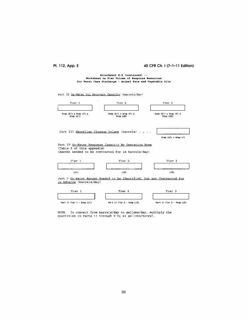
88
40 CFR Ch. I (7–1–11 Edition) Pt. 112, App. E
VerDate Mar<15>2010 10:37 Jul 28, 2011 Jkt 223165 PO 00000 Frm 00098 Fmt 8010 Sfmt 8006 Y:\SGML\223165.XXX 223165 ER
30JN
00.0
67<
/GP
H>
wre
ier-
avile
s on
DS
KG
BLS
3C1P
RO
D w
ith C
FR

89
Environmental Protection Agency Pt. 112, App. E
VerDate Mar<15>2010 10:37 Jul 28, 2011 Jkt 223165 PO 00000 Frm 00099 Fmt 8010 Sfmt 8006 Y:\SGML\223165.XXX 223165 ER
30JN
00.0
68<
/GP
H>
ER
30JN
00.0
69<
/GP
H>
wre
ier-
avile
s on
DS
KG
BLS
3C1P
RO
D w
ith C
FR

90
40 CFR Ch. I (7–1–11 Edition) Pt. 112, App. F
[59 FR 34111, July 1, 1994; 59 FR 49006, Sept. 26, 1994, as amended at 65 FR 40806, 40807, June 30, 2000; 65 FR 47325, Aug. 2, 2000; 66 FR 34560, June 29, 2001]
APPENDIX F TO PART 112—FACILITY- SPECIFIC RESPONSE PLAN
Table of Contents
1.0 Model Facility-Specific Response Plan 1.1 Emergency Response Action Plan 1.2 Facility Information 1.3 Emergency Response Information
1.3.1 Notification 1.3.2 Response Equipment List 1.3.3 Response Equipment Testing/Deploy-
ment 1.3.4 Personnel
1.3.5 Evacuation Plans 1.3.6 Qualified Individual’s Duties
1.4 Hazard Evaluation 1.4.1 Hazard Identification 1.4.2 Vulnerability Analysis 1.4.3 Analysis of the Potential for an Oil
Spill 1.4.4 Facility Reportable Oil Spill History
1.5 Discharge Scenarios 1.5.1 Small and Medium Discharges 1.5.2 Worst Case Discharge
1.6 Discharge Detection Systems 1.6.1 Discharge Detection By Personnel 1.6.2 Automated Discharge Detection
VerDate Mar<15>2010 10:37 Jul 28, 2011 Jkt 223165 PO 00000 Frm 00100 Fmt 8010 Sfmt 8003 Y:\SGML\223165.XXX 223165 ER
30JN
00.0
70<
/GP
H>
wre
ier-
avile
s on
DS
KG
BLS
3C1P
RO
D w
ith C
FR

91
Environmental Protection Agency Pt. 112, App. F
1.7 Plan Implementation 1.7.1 Response Resources for Small, Me-
dium, and Worst Case Spills 1.7.2 Disposal Plans 1.7.3 Containment and Drainage Planning
1.8 Self-Inspection, Drills/Exercises, and Re-sponse Training
1.8.1 Facility Self-Inspection 1.8.1.1 Tank Inspection 1.8.1.2 Response Equipment Inspection 1.8.1.3 Secondary Containment Inspection 1.8.2 Facility Drills/Exercises 1.8.2.1 Qualified Individual Notification
Drill Logs 1.8.2.2 Spill Management Team Tabletop
Exercise Logs 1.8.3 Response Training 1.8.3.1 Personnel Response Training Logs 1.8.3.2 Discharge Prevention Meeting Logs
1.9 Diagrams 1.10 Security 2.0 Response Plan Cover Sheet 3.0 Acronyms 4.0 References
1.0 Model Facility-Specific Response Plan
(A) Owners or operators of facilities regu-lated under this part which pose a threat of substantial harm to the environment by dis-charging oil into or on navigable waters or adjoining shorelines are required to prepare and submit facility-specific response plans to
EPA in accordance with the provisions in this appendix. This appendix further de-scribes the required elements in § 112.20(h).
(B) Response plans must be sent to the ap-propriate EPA Regional office. Figure F–1 of this Appendix lists each EPA Regional office and the address where owners or operators must submit their response plans. Those fa-cilities deemed by the Regional Adminis-trator (RA) to pose a threat of significant and substantial harm to the environment will have their plans reviewed and approved by EPA. In certain cases, information re-quired in the model response plan is similar to information currently maintained in the facility’s Spill Prevention, Control, and Countermeasures (SPCC) Plan as required by 40 CFR 112.3. In these cases, owners or opera-tors may reproduce the information and in-clude a photocopy in the response plan.
(C) A complex may develop a single re-sponse plan with a set of core elements for all regulating agencies and separate sections for the non-transportation-related and trans-portation-related components, as described in § 112.20(h). Owners or operators of large fa-cilities that handle, store, or transport oil at more than one geographically distinct loca-tion (e.g., oil storage areas at opposite ends of a single, continuous parcel of property) shall, as appropriate, develop separate sec-tions of the response plan for each storage area.
VerDate Mar<15>2010 10:37 Jul 28, 2011 Jkt 223165 PO 00000 Frm 00101 Fmt 8010 Sfmt 8002 Y:\SGML\223165.XXX 223165wre
ier-
avile
s on
DS
KG
BLS
3C1P
RO
D w
ith C
FR

92
40 CFR Ch. I (7–1–11 Edition) Pt. 112, App. F
1.1 Emergency Response Action Plan
Several sections of the response plan shall be co-located for easy access by response per-sonnel during an actual emergency or oil dis-charge. This collection of sections shall be called the Emergency Response Action Plan. The Agency intends that the Action Plan
contain only as much information as is nec-essary to combat the discharge and be ar-ranged so response actions are not delayed. The Action Plan may be arranged in a num-ber of ways. For example, the sections of the Emergency Response Action Plan may be photocopies or condensed versions of the
VerDate Mar<15>2010 10:37 Jul 28, 2011 Jkt 223165 PO 00000 Frm 00102 Fmt 8010 Sfmt 8002 Y:\SGML\223165.XXX 223165 EC
01M
R92
.015
</G
PH
>
wre
ier-
avile
s on
DS
KG
BLS
3C1P
RO
D w
ith C
FR

93
Environmental Protection Agency Pt. 112, App. F
1 A wellhead protection area is defined as the surface and subsurface area surrounding a water well or wellfield, supplying a public water system, through which contaminants are reasonably likely to move toward and reach such water well or wellfield. For fur-ther information regarding State and terri-tory protection programs, facility owners or operators may contact the SDWA Hotline at 1–800–426–4791.
forms included in the associated sections of the response plan. Each Emergency Response Action Plan section may be tabbed for quick reference. The Action Plan shall be main-tained in the front of the same binder that contains the complete response plan or it shall be contained in a separate binder. In the latter case, both binders shall be kept to-gether so that the entire plan can be accessed by the qualified individual and ap-propriate spill response personnel. The Emergency Response Action Plan shall be made up of the following sections:
1. Qualified Individual Information (Section 1.2) partial
2. Emergency Notification Phone List (Sec-tion 1.3.1) partial
3. Spill Response Notification Form (Section 1.3.1) partial
4. Response Equipment List and Location (Section 1.3.2) complete
5. Response Equipment Testing and Deploy-ment (Section 1.3.3) complete
6. Facility Response Team (Section 1.3.4) partial
7. Evacuation Plan (Section 1.3.5) condensed 8. Immediate Actions (Section 1.7.1) com-
plete 9. Facility Diagram (Section 1.9) complete
1.2 Facility Information
The facility information form is designed to provide an overview of the site and a de-scription of past activities at the facility. Much of the information required by this section may be obtained from the facility’s existing SPCC Plan.
1.2.1 Facility name and location: Enter fa-cility name and street address. Enter the ad-dress of corporate headquarters only if cor-porate headquarters are physically located at the facility. Include city, county, state, zip code, and phone number.
1.2.2 Latitude and Longitude: Enter the latitude and longitude of the facility. In-clude degrees, minutes, and seconds of the main entrance of the facility.
1.2.3 Wellhead Protection Area: Indicate if the facility is located in or drains into a wellhead protection area as defined by the Safe Drinking Water Act of 1986 (SDWA). 1 The response plan requirements in the Well-head Protection Program are outlined by the
State or Territory in which the facility re-sides.
1.2.4 Owner/operator: Write the name of the company or person operating the facility and the name of the person or company that owns the facility, if the two are different. List the address of the owner, if the two are different.
1.2.5 Qualified Individual: Write the name of the qualified individual for the entire fa-cility. If more than one person is listed, each individual indicated in this section shall have full authority to implement the facility response plan. For each individual, list: name, position, home and work addresses (street addresses, not P.O. boxes), emergency phone number, and specific response training experience.
1.2.6 Date of Oil Storage Start-up: Enter the year which the present facility first started storing oil.
1.2.7 Current Operation: Briefly describe the facility’s operations and include the North American Industrial Classification System (NAICS) code.
1.2.8 Dates and Type of Substantial Expan-sion: Include information on expansions that have occurred at the facility. Examples of such expansions include, but are not limited to: Throughput expansion, addition of a product line, change of a product line, and installation of additional oil storage capac-ity. The data provided shall include all facil-ity historical information and detail the ex-pansion of the facility. An example of sub-stantial expansion is any material alteration of the facility which causes the owner or op-erator of the facility to re-evaluate and in-crease the response equipment necessary to adequately respond to a worst case discharge from the facility. Date of Last Update: lll
FACILITY INFORMATION FORM
Facility Name: lllllllllllllll
Location (Street Address): llllllll
City: lll State: lll Zip: lll
County: lll Phone Number: ( ) lll
Latitude: lll Degrees lll Minutes lll Seconds
Longitude: lll Degrees lll Minutes lll Seconds
Wellhead Protection Area: lllllllll
Owner: lllllllllllllllllll
Owner Location (Street Address): llll
(if different from Facility Address) City: lll State:lll Zip: lll
County: lll Phone Number: ( ) lll
Operator (if not Owner): llllllllll
Qualified Individual(s): (attach additional sheets if more than one)
Name: lllllllllllllllllll
Position: lllllllllllllllll
Work Address: lllllllllllllll
Home Address: llllllllllllll
Emergency Phone Number: ( ) llll
VerDate Mar<15>2010 10:37 Jul 28, 2011 Jkt 223165 PO 00000 Frm 00103 Fmt 8010 Sfmt 8002 Y:\SGML\223165.XXX 223165wre
ier-
avile
s on
DS
KG
BLS
3C1P
RO
D w
ith C
FR

94
40 CFR Ch. I (7–1–11 Edition) Pt. 112, App. F
Date of Oil Storage Start-up: llllllll
Current Operations: lllllllllllll
llllllllllllllllllllllll
llllllllllllllllllllllll
Date(s) and Type(s) of Substantial Expan-sion(s): llllllllllllllllll
llllllllllllllllllllllll
(Attach additional sheets if necessary)
1.3 Emergency Response Information
(A) The information provided in this sec-tion shall describe what will be needed in an actual emergency involving the discharge of oil or a combination of hazardous substances and oil discharge. The Emergency Response Information section of the plan must include the following components:
(1) The information provided in the Emer-gency Notification Phone List in section 1.3.1 identifies and prioritizes the names and phone numbers of the organizations and per-sonnel that need to be notified immediately in the event of an emergency. This section shall include all the appropriate phone num-bers for the facility. These numbers must be verified each time the plan is updated. The contact list must be accessible to all facility employees to ensure that, in case of a dis-charge, any employee on site could imme-diately notify the appropriate parties.
(2) The Spill Response Notification Form in section 1.3.1 creates a checklist of infor-mation that shall be provided to the Na-tional Response Center (NRC) and other re-sponse personnel. All information on this checklist must be known at the time of noti-fication, or be in the process of being col-lected. This notification form is based on a similar form used by the NRC. Note: Do not delay spill notification to collect the infor-mation on the list.
(3) Section 1.3.2 provides a description of the facility’s list of emergency response equipment and location of the response equipment. When appropriate, the amount of oil that emergency response equipment can handle and any limitations (e.g., launching sites) must be described.
(4) Section 1.3.3 provides information re-garding response equipment tests and de-ployment drills. Response equipment deploy-ment exercises shall be conducted to ensure that response equipment is operational and the personnel who would operate the equip-ment in a spill response are capable of de-ploying and operating it. Only a representa-tive sample of each type of response equip-ment needs to be deployed and operated, as long as the remainder is properly main-tained. If appropriate, testing of response equipment may be conducted while it is being deployed. Facilities without facility- owned response equipment must ensure that the oil spill removal organization that is identified in the response plan to provide this response equipment certifies that the deployment exercises have been met. Refer
to the National Preparedness for Response Exercise Program (PREP) Guidelines (see Appendix E to this part, section 13, for avail-ability), which satisfy Oil Pollution Act (OPA) response exercise requirements.
(5) Section 1.3.4 lists the facility response personnel, including those employed by the facility and those under contract to the fa-cility for response activities, the amount of time needed for personnel to respond, their responsibility in the case of an emergency, and their level of response training. Three different forms are included in this section. The Emergency Response Personnel List shall be composed of all personnel employed by the facility whose duties involve respond-ing to emergencies, including oil discharges, even when they are not physically present at the site. An example of this type of person would be the Building Engineer-in-Charge or Plant Fire Chief. The second form is a list of the Emergency Response Contractors (both primary and secondary) retained by the fa-cility. Any changes in contractor status must be reflected in updates to the response plan. Evidence of contracts with response contractors shall be included in this section so that the availability of resources can be verified. The last form is the Facility Re-sponse Team List, which shall be composed of both emergency response personnel (ref-erenced by job title/position) and emergency response contractors, included in one of the two lists described above, that will respond immediately upon discovery of an oil dis-charge or other emergency (i.e., the first people to respond). These are to be persons normally on the facility premises or primary response contractors. Examples of these per-sonnel would be the Facility Hazardous Ma-terials (HAZMAT) Spill Team 1, Facility Fire Engine Company 1, Production Super-visor, or Transfer Supervisor. Company per-sonnel must be able to respond immediately and adequately if contractor support is not available.
(6) Section 1.3.5 lists factors that must, as appropriate, be considered when preparing an evacuation plan.
(7) Section 1.3.6 references the responsibil-ities of the qualified individual for the facil-ity in the event of an emergency.
(B) The information provided in the emer-gency response section will aid in the assess-ment of the facility’s ability to respond to a worst case discharge and will identify addi-tional assistance that may be needed. In ad-dition, the facility owner or operator may want to produce a wallet-size card con-taining a checklist of the immediate re-sponse and notification steps to be taken in the event of an oil discharge.
1.3.1 Notification
Date of Last Update: llllllllllll
VerDate Mar<15>2010 10:37 Jul 28, 2011 Jkt 223165 PO 00000 Frm 00104 Fmt 8010 Sfmt 8002 Y:\SGML\223165.XXX 223165wre
ier-
avile
s on
DS
KG
BLS
3C1P
RO
D w
ith C
FR

95
Environmental Protection Agency Pt. 112, App. F
EMERGENCY NOTIFICATION PHONE LIST WHOM TO NOTIFY
Reporter’s Name: llllllllllllll
Date: llllllllllllllllllll
Facility Name: lllllllllllllll
Owner Name: llllllllllllllll
Facility Identification Number: llllll
Date and Time of Each NRC Notification: l
Organization Phone No.
1. National Response Center (NRC): 1–800–424–8802
2. Qualified Individual:
Evening Phone:
3. Company Response Team:
Evening Phone:
4. Federal On-Scene Coordinator (OSC) and/or Regional Response Center (RRC):
Evening Phone(s):
Pager Number(s):
5. Local Response Team (Fire Dept./Co-operatives):
6. Fire Marshall:
Evening Phone:
7. State Emergency Response Commis-sion (SERC):
Evening Phone:
8. State Police:
9. Local Emergency Planning Committee (LEPC):
10. Local Water Supply System:
Evening Phone:
11. Weather Report:
12. Local Television/Radio Station for Evacuation Notification:
13. Hospitals:
SPILL RESPONSE NOTIFICATION FORM
Reporter’s Last Name: lllllllllll
First: llllllllllllllllllll
M.I.: lllllllllllllllllllll
Position: llllllllllllllllll
Phone Numbers:
Day ( ) – Evening ( ) –
Company: llllllllllllllllll
Organization Type: lllllllllllll
Address: lllllllllllllllllll
llllllllllllllllllllllll
City: lllllllllllllllllllll
State: llllllllllllllllllll
Zip: lllllllllllllllllllll
Were Materials Discharged? lll (Y/N) Con-fidential? lll (Y/N)
Meeting Federal Obligations to Report? lll (Y/N) Date Called: lll
Calling for Responsible Party? lll (Y/N) Time Called: lll
Incident Description
Source and/or Cause of Incident: llllll
llllllllllllllllllllllll
llllllllllllllllllllllll
llllllllllllllllllllllll
llllllllllllllllllllllll
Date of Incident: llllllllllllll
Time of Incident: lll AM/PM
Incident Address/Location: lllllllll
llllllllllllllllllllllll
Nearest City:llllllll State: lll
County: llll Zip: llll
Distance from City: lll Units of Measure: lll Direction from City: lll
Section: llll Township: llll Range: llll Borough: llll
Container Type: lll Tank Oil Storage Ca-pacity: llll Units of Measure: lll
Facility Oil Storage Capacity: llll Units of Measure: lll
Facility Latitude: lll Degrees lll Min-utes lll Seconds
Facility Longitude: lll Degrees lll
Minutes lll Seconds
Material
CHRIS Code Discharged quan-tity Unit of measure Material Dis-
charged in water Quantity Unit of measure
VerDate Mar<15>2010 10:37 Jul 28, 2011 Jkt 223165 PO 00000 Frm 00105 Fmt 8010 Sfmt 8002 Y:\SGML\223165.XXX 223165wre
ier-
avile
s on
DS
KG
BLS
3C1P
RO
D w
ith C
FR

96
40 CFR Ch. I (7–1–11 Edition) Pt. 112, App. F
Response Action
Actions Taken to Correct, Control or Miti-gate Incident:
llllllllllllllllllllllll
llllllllllllllllllllllll
llllllllllllllllllllllll
llllllllllllllllllllllll
Impact
Number of Injuries: lll Number of Deaths: lll
Were there Evacuations? lll (Y/N) Num-ber Evacuated: lll
Was there any Damage? lll (Y/N) Damage in Dollars (approximate): lllll
Medium Affected: llllllllllllll
Description: lllllllllllllllll
More Information about Medium: lllll
llllllllllllllllllllllll
llllllllllllllllllllllll
Additional Information
Any information about the incident not re-corded elsewhere in the report:
llllllllllllllllllllllll
llllllllllllllllllllllll
llllllllllllllllllllllll
Caller Notifications
EPA? lll (Y/N) USCG? lll (Y/N) State? lll (Y/N)
Other? lll (Y/N) Describe: llllll
1.3.2 Response Equipment List
Date of Last Update:lll
FACILITY RESPONSE EQUIPMENT LIST
1. Skimmers/Pumps—Operational Status: l
Type, Model, and Year: llllllllll
llllllllllllllllllllll
Type Model Year Number: llllllllllllllllll
Capacity: llll gal./min. Daily Effective Recovery Rate: llllll
Storage Location(s): lllllllllll
Date Fuel Last Changed: lllllllll
2. Boom—Operational Status: llllllll
Type, Model, and Year: llllllllll
Type Model Year Number: llllllllllllllllll
Size (length): llll ft. Containment Area: llll sq. ft. Storage Location: lllllllllllll
3. Chemicals Stored (Dispersants listed on EPA’s NCP Product Schedule)
Type Amount Date purchased
Treatment capacity
Storage location
Were appropriate procedures used to re-ceive approval for use of dispersants in ac-cordance with the NCP (40 CFR 300.910) and the Area Contingency Plan (ACP), where ap-plicable?lll (Y/N).
Name and State of On-Scene Coordinator (OSC) authorizing use: lll .
Date Authorized: lll . 4. Dispersant Dispensing Equipment—Oper-
ational Status: lll .
Type and year Capacity Storage location
Response time
(minutes)
5. Sorbents—Operational Status: llllll
Type and Year Purchased: llllllll
Amount: llllllllllllllllll
Absorption Capacity (gal.): llllllll
Storage Location(s): lllllllllll
6. Hand Tools—Operational Status: lllll
Type and year Quantity Storage location
VerDate Mar<15>2010 10:37 Jul 28, 2011 Jkt 223165 PO 00000 Frm 00106 Fmt 8010 Sfmt 8002 Y:\SGML\223165.XXX 223165wre
ier-
avile
s on
DS
KG
BLS
3C1P
RO
D w
ith C
FR
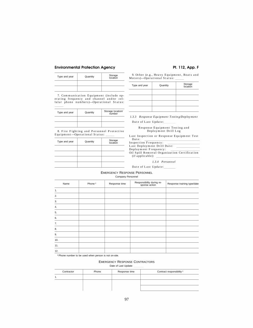
97
Environmental Protection Agency Pt. 112, App. F
Type and year Quantity Storage location
7. Communication Equipment (include op-erating frequency and channel and/or cel-lular phone numbers)—Operational Status: lll
Type and year Quantity Storage location/ number
8. Fire Fighting and Personnel Protective Equipment—Operational Status: lll
Type and year Quantity Storage location
9. Other (e.g., Heavy Equipment, Boats and Motors)—Operational Status: lll
Type and year Quantity Storage location
1.3.3 Response Equipment Testing/Deployment
Date of Last Update:llll
Response Equipment Testing and Deployment Drill Log
Last Inspection or Response Equipment Test Date: lllllllllllllllllll
Inspection Frequency: lllllllllll
Last Deployment Drill Date: llllllll
Deployment Frequency: llllllllll
Oil Spill Removal Organization Certification (if applicable): lllllllllllllll
1.3.4 Personnel
Date of Last Update:llll
EMERGENCY RESPONSE PERSONNEL Company Personnel
Name Phone 1 Response time Responsibility during re-sponse action Response training type/date
1.
2.
3.
4.
5.
6.
7.
8.
9.
10.
11.
12.
1 Phone number to be used when person is not on-site.
EMERGENCY RESPONSE CONTRACTORS Date of Last Update: llll
Contractor Phone Response time Contract responsibility 1
1.
VerDate Mar<15>2010 10:37 Jul 28, 2011 Jkt 223165 PO 00000 Frm 00107 Fmt 8010 Sfmt 8002 Y:\SGML\223165.XXX 223165wre
ier-
avile
s on
DS
KG
BLS
3C1P
RO
D w
ith C
FR

98
40 CFR Ch. I (7–1–11 Edition) Pt. 112, App. F
EMERGENCY RESPONSE CONTRACTORS—Continued Date of Last Update: llll
Contractor Phone Response time Contract responsibility 1
2.
3.
4.
1 Include evidence of contracts/agreements with response contractors to ensure the availability of personnel and response equipment.
FACILITY RESPONSE TEAM Date of Last Update:llll
Team member Response time (minutes) Phone or pager number (day/evening)
Qualified Individual: /
/
/
/
/
/
/
/
/
/
/
/
/
/
/
/
/
/
NOTE: If the facility uses contracted help in an emergency response situation, the owner or operator must provide the contrac-tors’ names and review the contractors’ capacities to provide adequate personnel and response equipment.
VerDate Mar<15>2010 10:37 Jul 28, 2011 Jkt 223165 PO 00000 Frm 00108 Fmt 8010 Sfmt 8002 Y:\SGML\223165.XXX 223165wre
ier-
avile
s on
DS
KG
BLS
3C1P
RO
D w
ith C
FR

99
Environmental Protection Agency Pt. 112, App. F
1.3.5 Evacuation Plans
1.3.5.1 Based on the analysis of the facil-ity, as discussed elsewhere in the plan, a fa-cility-wide evacuation plan shall be devel-oped. In addition, plans to evacuate parts of the facility that are at a high risk of expo-sure in the event of a discharge or other re-lease must be developed. Evacuation routes must be shown on a diagram of the facility (see section 1.9 of this appendix). When de-veloping evacuation plans, consideration must be given to the following factors, as ap-propriate:
(1) Location of stored materials; (2) Hazard imposed by discharged material; (3) Discharge flow direction; (4) Prevailing wind direction and speed; (5) Water currents, tides, or wave condi-
tions (if applicable); (6) Arrival route of emergency response
personnel and response equipment; (7) Evacuation routes; (8) Alternative routes of evacuation; (9) Transportation of injured personnel to
nearest emergency medical facility; (10) Location of alarm/notification sys-
tems; (11) The need for a centralized check-in
area for evacuation validation (roll call); (12) Selection of a mitigation command
center; and (13) Location of shelter at the facility as
an alternative to evacuation. 1.3.5.2 One resource that may be helpful
to owners or operators in preparing this sec-tion of the response plan is The Handbook of Chemical Hazard Analysis Procedures by the Federal Emergency Management Agency (FEMA), Department of Transportation (DOT), and EPA. The Handbook of Chemical Hazard Analysis Procedures is available from: FEMA , Publication Office, 500 C. Street, S.W., Washington, DC 20472, (202) 646–3484.
1.3.5.3 As specified in § 112.20(h)(1)(vi), the facility owner or operator must reference ex-isting community evacuation plans, as ap-propriate.
1.3.6 Qualified Individual’s Duties
The duties of the designated qualified indi-vidual are specified in § 112.20(h)(3)(ix). The qualified individual’s duties must be de-scribed and be consistent with the minimum requirements in § 112.20(h)(3)(ix). In addition, the qualified individual must be identified with the Facility Information in section 1.2 of the response plan.
1.4 Hazard Evaluation
This section requires the facility owner or operator to examine the facility’s operations closely and to predict where discharges could occur. Hazard evaluation is a widely used in-dustry practice that allows facility owners or operators to develop a complete under-standing of potential hazards and the re-
sponse actions necessary to address these hazards. The Handbook of Chemical Hazard Analysis Procedures, prepared by the EPA, DOT, and the FEMA and the Hazardous Mate-rials Emergency Planning Guide (NRT–1), pre-pared by the National Response Team are good references for conducting a hazard anal-ysis. Hazard identification and evaluation will assist facility owners or operators in planning for potential discharges, thereby reducing the severity of discharge impacts that may occur in the future. The evaluation also may help the operator identify and cor-rect potential sources of discharges. In addi-tion, special hazards to workers and emer-gency response personnel’s health and safety shall be evaluated, as well as the facility’s oil spill history.
1.4.1 Hazard Identification
The Tank and Surface Impoundment (SI) forms, or their equivalent, that are part of this section must be completed according to the directions below. (‘‘Surface Impound-ment’’ means a facility or part of a facility which is a natural topographic depression, man-made excavation, or diked area formed primarily of earthen materials (although it may be lined with man-made materials), which is designed to hold an accumulation of liquid wastes or wastes containing free liq-uids, and which is not an injection well or a seepage facility.) Similar worksheets, or their equivalent, must be developed for any other type of storage containers.
(1) List each tank at the facility with a separate and distinct identifier. Begin above-ground tank identifiers with an ‘‘A’’ and be-lowground tank identifiers with a ‘‘B’’, or submit multiple sheets with the aboveground tanks and belowground tanks on separate sheets.
(2) Use gallons for the maximum capacity of a tank; and use square feet for the area.
(3) Using the appropriate identifiers and the following instructions, fill in the appro-priate forms:
(a) Tank or SI number—Using the afore-mentioned identifiers (A or B) or multiple reporting sheets, identify each tank or SI at the facility that stores oil or hazardous ma-terials.
(b) Substance Stored—For each tank or SI identified, record the material that is stored therein. If the tank or SI is used to store more than one material, list all of the stored materials.
(c) Quantity Stored—For each material stored in each tank or SI, report the average volume of material stored on any given day.
(d) Tank Type or Surface Area/Year—For each tank, report the type of tank (e.g., floating top), and the year the tank was originally installed. If the tank has been re-fabricated, the year that the latest refabrica-tion was completed must be recorded in pa-rentheses next to the year installed. For
VerDate Mar<15>2010 10:37 Jul 28, 2011 Jkt 223165 PO 00000 Frm 00109 Fmt 8010 Sfmt 8002 Y:\SGML\223165.XXX 223165wre
ier-
avile
s on
DS
KG
BLS
3C1P
RO
D w
ith C
FR

100
40 CFR Ch. I (7–1–11 Edition) Pt. 112, App. F
each SI, record the surface area of the im-poundment and the year it went into service.
(e) Maximum Capacity—Record the oper-ational maximum capacity for each tank and SI. If the maximum capacity varies with the season, record the upper and lower limits.
(f) Failure/Cause—Record the cause and date of any tank or SI failure which has re-sulted in a loss of tank or SI contents.
(4) Using the numbers from the tank and SI forms, label a schematic drawing of the facility. This drawing shall be identical to any schematic drawings included in the SPCC Plan.
(5) Using knowledge of the facility and its operations, describe the following in writing:
(a) The loading and unloading of transpor-tation vehicles that risk the discharge of oil or release of hazardous substances during transport processes. These operations may include loading and unloading of trucks, railroad cars, or vessels. Estimate the vol-ume of material involved in transfer oper-
ations, if the exact volume cannot be deter-mined.
(b) Day-to-day operations that may present a risk of discharging oil or releasing a hazardous substance. These activities in-clude scheduled venting, piping repair or re-placement, valve maintenance, transfer of tank contents from one tank to another, etc. (not including transportation-related activi-ties). Estimate the volume of material in-volved in these operations, if the exact vol-ume cannot be determined.
(c) The secondary containment volume as-sociated with each tank and/or transfer point at the facility. The numbering scheme devel-oped on the tables, or an equivalent system, must be used to identify each containment area. Capacities must be listed for each indi-vidual unit (tanks, slumps, drainage traps, and ponds), as well as the facility total.
(d) Normal daily throughput for the facil-ity and any effect on potential discharge vol-umes that a negative or positive change in that throughput may cause.
HAZARD IDENTIFICATION TANKS 1 Date of Last Update: llll
Tank No. Substance Stored
(Oil and Hazardous Substance)
Quantity Stored (gallons) Tank Type/Year Maximum Capacity
(gallons) Failure/Cause
1 Tank = any container that stores oil. Attach as many sheets as necessary.
HAZARD IDENTIFICATION SURFACE IMPOUNDMENTS (SIS) Date of Last Update: llll
SI No. Substance Stored Quantity Stored (gallons) Surface Area/Year Maximum Capacity
(gallons) Failure/Cause
VerDate Mar<15>2010 10:37 Jul 28, 2011 Jkt 223165 PO 00000 Frm 00110 Fmt 8010 Sfmt 8002 Y:\SGML\223165.XXX 223165wre
ier-
avile
s on
DS
KG
BLS
3C1P
RO
D w
ith C
FR

101
Environmental Protection Agency Pt. 112, App. F
2 Refer to the DOC/NOAA ‘‘Guidance for Facility and Vessel Response Plans: Fish and Wildlife and Sensitive Environments’’ (See appendix E to this part, section 13, for avail-ability).
3 As described in 40 CFR part 110, report-able oil spills are those that: (a) violate ap-plicable water quality standards, or (b) cause a film or sheen upon or discoloration of the surface of the water or adjoining shorelines or cause a sludge or emulsion to be deposited beneath the surface of the water or upon ad-joining shorelines.
HAZARD IDENTIFICATION SURFACE IMPOUNDMENTS (SIS)—Continued Date of Last Update: llll
SI No. Substance Stored Quantity Stored (gallons) Surface Area/Year Maximum Capacity
(gallons) Failure/Cause
Attach as many sheets as necessary.
1.4.2 Vulnerability Analysis
The vulnerability analysis shall address the potential effects (i.e., to human health, property, or the environment) of an oil dis-charge. Attachment C–III to Appendix C to this part provides a method that owners or operators shall use to determine appropriate distances from the facility to fish and wild-life and sensitive environments. Owners or operators can use a comparable formula that is considered acceptable by the RA. If a com-parable formula is used, documentation of the reliability and analytical soundness of the formula must be attached to the re-sponse plan cover sheet. This analysis must be prepared for each facility and, as appro-priate, must discuss the vulnerability of:
(1) Water intakes (drinking, cooling, or other);
(2) Schools; (3) Medical facilities; (4) Residential areas; (5) Businesses; (6) Wetlands or other sensitive environ-
ments; 2 (7) Fish and wildlife; (8) Lakes and streams; (9) Endangered flora and fauna; (10) Recreational areas; (11) Transportation routes (air, land, and
water); (12) Utilities; and (13) Other areas of economic importance
(e.g., beaches, marinas) including terrestri-ally sensitive environments, aquatic envi-ronments, and unique habitats.
1.4.3 Analysis of the Potential for an Oil Discharge
Each owner or operator shall analyze the probability of a discharge occurring at the
facility. This analysis shall incorporate fac-tors such as oil discharge history, horizontal range of a potential discharge, and vulner-ability to natural disaster, and shall, as ap-propriate, incorporate other factors such as tank age. This analysis will provide informa-tion for developing discharge scenarios for a worst case discharge and small and medium discharges and aid in the development of techniques to reduce the size and frequency of discharges. The owner or operator may need to research the age of the tanks the oil discharge history at the facility.
1.4.4 Facility Reportable Oil Spill History
Briefly describe the facility’s reportable oil spill 3 history for the entire life of the fa-cility to the extent that such information is reasonably identifiable, including:
(1) Date of discharge(s); (2) List of discharge causes; (3) Material(s) discharged; (4) Amount discharged in gallons; (5) Amount of discharge that reached navi-
gable waters, if applicable; (6) Effectiveness and capacity of secondary
containment; (7) Clean-up actions taken; (8) Steps taken to reduce possibility of re-
currence; (9) Total oil storage capacity of the tank(s)
or impoundment(s) from which the material discharged;
(10) Enforcement actions; (11) Effectiveness of monitoring equip-
ment; and (12) Description(s) of how each oil dis-
charge was detected.
VerDate Mar<15>2010 10:37 Jul 28, 2011 Jkt 223165 PO 00000 Frm 00111 Fmt 8010 Sfmt 8003 Y:\SGML\223165.XXX 223165wre
ier-
avile
s on
DS
KG
BLS
3C1P
RO
D w
ith C
FR

102
40 CFR Ch. I (7–1–11 Edition) Pt. 112, App. F
The information solicited in this section may be similar to requirements in 40 CFR 112.4(a). Any duplicate information required by § 112.4(a) may be photocopied and inserted.
1.5 Discharge Scenarios
In this section, the owner or operator is re-quired to provide a description of the facili-ty’s worst case discharge, as well as a small and medium discharge, as appropriate. A multi-level planning approach has been cho-sen because the response actions to a dis-charge (i.e., necessary response equipment, products, and personnel) are dependent on the magnitude of the discharge. Planning for lesser discharges is necessary because the nature of the response may be qualitatively different depending on the quantity of the discharge. The facility owner or operator shall discuss the potential direction of the discharge pathway.
1.5.1 Small and Medium Discharges
1.5.1.1 To address multi-level planning re-quirements, the owner or operator must con-sider types of facility-specific discharge sce-narios that may contribute to a small or me-dium discharge. The scenarios shall account for all the operations that take place at the facility, including but not limited to:
(1) Loading and unloading of surface trans-portation;
(2) Facility maintenance; (3) Facility piping; (4) Pumping stations and sumps; (5) Oil storage tanks; (6) Vehicle refueling; and (7) Age and condition of facility and com-
ponents. 1.5.1.2 The scenarios shall also consider
factors that affect the response efforts re-quired by the facility. These include but are not limited to:
(1) Size of the discharge; (2) Proximity to downgradient wells, wa-
terways, and drinking water intakes; (3) Proximity to fish and wildlife and sen-
sitive environments; (4) Likelihood that the discharge will trav-
el offsite (i.e., topography, drainage); (5) Location of the material discharged
(i.e., on a concrete pad or directly on the soil);
(6) Material discharged; (7) Weather or aquatic conditions (i.e.,
river flow); (8) Available remediation equipment; (9) Probability of a chain reaction of fail-
ures; and (10) Direction of discharge pathway.
1.5.2 Worst Case Discharge
1.5.2.1 In this section, the owner or oper-ator must identify the worst case discharge volume at the facility. Worksheets for pro-duction and non-production facility owners
or operators to use when calculating worst case discharge are presented in Appendix D to this part. When planning for the worst case discharge response, all of the aforemen-tioned factors listed in the small and me-dium discharge section of the response plan shall be addressed.
1.5.2.2 For onshore storage facilities and production facilities, permanently manifolded oil storage tanks are defined as tanks that are designed, installed, and/or op-erated in such a manner that the multiple tanks function as one storage unit (i.e., mul-tiple tank volumes are equalized). In this section of the response plan, owners or oper-ators must provide evidence that oil storage tanks with common piping or piping systems are not operated as one unit. If such evidence is provided and is acceptable to the RA, the worst case discharge volume shall be based on the combined oil storage capacity of all manifold tanks or the oil storage capacity of the largest single oil storage tank within the secondary containment area, whichever is greater. For permanently manifolded oil storage tanks that function as one storage unit, the worst case discharge shall be based on the combined oil storage capacity of all manifolded tanks or the oil storage capacity of the largest single tank within a secondary containment area, whichever is greater. For purposes of the worst case discharge calcula-tion, permanently manifolded oil storage tanks that are separated by internal divi-sions for each tank are considered to be sin-gle tanks and individual manifolded tank volumes are not combined.
1.6 Discharge Detection Systems
In this section, the facility owner or oper-ator shall provide a detailed description of the procedures and equipment used to detect discharges. A section on discharge detection by personnel and a discussion of automated discharge detection, if applicable, shall be included for both regular operations and after hours operations. In addition, the facil-ity owner or operator shall discuss how the reliability of any automated system will be checked and how frequently the system will be inspected.
1.6.1 Discharge Detection by Personnel
In this section, facility owners or opera-tors shall describe the procedures and per-sonnel that will detect any discharge of oil or release of a hazardous substance. A thor-ough discussion of facility inspections must be included. In addition, a description of ini-tial response actions shall be addressed. This section shall reference section 1.3.1 of the re-sponse plan for emergency response informa-tion.
VerDate Mar<15>2010 10:37 Jul 28, 2011 Jkt 223165 PO 00000 Frm 00112 Fmt 8010 Sfmt 8002 Y:\SGML\223165.XXX 223165wre
ier-
avile
s on
DS
KG
BLS
3C1P
RO
D w
ith C
FR

103
Environmental Protection Agency Pt. 112, App. F
1.6.2 Automated Discharge Detection
In this section, facility owners or opera-tors must describe any automated discharge detection equipment that the facility has in place. This section shall include a discussion of overfill alarms, secondary containment sensors, etc. A discussion of the plans to verify an automated alarm and the actions to be taken once verified must also be in-cluded.
1.7 Plan Implementation
In this section, facility owners or opera-tors must explain in detail how to imple-ment the facility’s emergency response plan by describing response actions to be carried out under the plan to ensure the safety of the facility and to mitigate or prevent dis-charges described in section 1.5 of the re-sponse plan. This section shall include the identification of response resources for small, medium, and worst case discharges; disposal plans; and containment and drain-age planning. A list of those personnel who would be involved in the cleanup shall be identified. Procedures that the facility will use, where appropriate or necessary, to up-date their plan after an oil discharge event and the time frame to update the plan must be described.
1.7.1 Response Resources for Small, Medium, and Worst Case Discharages
1.7.1.1 Once the discharge scenarios have been identified in section 1.5 of the response plan, the facility owner or operator shall identify and describe implementation of the response actions. The facility owner or oper-ator shall demonstrate accessibility to the proper response personnel and equipment to effectively respond to all of the identified discharge scenarios. The determination and demonstration of adequate response capa-bility are presented in Appendix E to this part. In addition, steps to expedite the clean-up of oil discharges must be discussed. At a minimum, the following items must be ad-dressed:
(1) Emergency plans for spill response; (2) Additional response training; (3) Additional contracted help; (4) Access to additional response equip-
ment/experts; and (5) Ability to implement the plan including
response training and practice drills. 1.7.1.2A recommended form detailing im-
mediate actions follows.
OIL SPILL RESPONSE—IMMEDIATE ACTIONS
1. Stop the product flow Act quickly to secure pumps, close valves, etc.
OIL SPILL RESPONSE—IMMEDIATE ACTIONS— Continued
2. Warn personnel .......... Enforce safety and secu-rity measures.
3. Shut off ignition sources.
Motors, electrical circuits, open flames, etc.
4. Initiate containment .... Around the tank and/or in the water with oil boom.
5. Notify NRC ................. 1–800–424–8802 6. Notify OSC 7. Notify, as appropriate
Source: FOSS, Oil Spill Response—Emergency Proce-dures, Revised December 3, 1992.
1.7.2 Disposal Plans
1.7.2.1 Facility owners or operators must describe how and where the facility intends to recover, reuse, decontaminate, or dispose of materials after a discharge has taken place. The appropriate permits required to transport or dispose of recovered materials according to local, State, and Federal re-quirements must be addressed. Materials that must be accounted for in the disposal plan, as appropriate, include:
(1) Recovered product; (2) Contaminated soil; (3) Contaminated equipment and mate-
rials, including drums, tank parts, valves, and shovels;
(4) Personnel protective equipment; (5) Decontamination solutions; (6) Adsorbents; and (7) Spent chemicals. 1.7.2.2 These plans must be prepared in ac-
cordance with Federal (e.g., the Resource Conservation and Recovery Act [RCRA]), State, and local regulations, where applica-ble. A copy of the disposal plans from the fa-cility’s SPCC Plan may be inserted with this section, including any diagrams in those plans.
Material Disposal fa-cility Location RCRA per-
mit/manifest
1.
2.
3.
4.
1.7.3 Containment and Drainage Planning
A proper plan to contain and control a dis-charge through drainage may limit the threat of harm to human health and the en-vironment. This section shall describe how to contain and control a discharge through drainage, including:
VerDate Mar<15>2010 10:37 Jul 28, 2011 Jkt 223165 PO 00000 Frm 00113 Fmt 8010 Sfmt 8002 Y:\SGML\223165.XXX 223165wre
ier-
avile
s on
DS
KG
BLS
3C1P
RO
D w
ith C
FR

104
40 CFR Ch. I (7–1–11 Edition) Pt. 112, App. F
(1) The available volume of containment (use the information presented in section 1.4.1 of the response plan);
(2) The route of drainage from oil storage and transfer areas;
(3) The construction materials used in drainage troughs;
(4) The type and number of valves and sep-arators used in the drainage system;
(5) Sump pump capacities; (6) The containment capacity of weirs and
booms that might be used and their location (see section 1.3.2 of this appendix); and
(7) Other cleanup materials. In addition, a facility owner or operator
must meet the inspection and monitoring re-quirements for drainage contained in 40 CFR part 112, subparts A through C. A copy of the containment and drainage plans that are re-quired in 40 CFR part 112, subparts A through C may be inserted in this section, including any diagrams in those plans.
NOTE: The general permit for stormwater drainage may contain additional require-ments.
1.8 Self-Inspection, Drills/Exercises, and Response Training
The owner or operator must develop pro-grams for facility response training and for drills/exercises according to the require-ments of 40 CFR 112.21. Logs must be kept for facility drills/exercises, personnel response training, and spill prevention meetings. Much of the recordkeeping information re-quired by this section is also contained in the SPCC Plan required by 40 CFR 112.3. These logs may be included in the facility re-sponse plan or kept as an annex to the facil-ity response plan.
1.8.1 Facility Self-Inspection
Under 40 CFR 112.7(e), you must include the written procedures and records of inspec-tions for each facility in the SPCC Plan. You must include the inspection records for each container, secondary containment, and item of response equipment at the facility. You must cross-reference the records of inspec-
tions of each container and secondary con-tainment required by 40 CFR 112.7(e) in the facility response plan. The inspection record of response equipment is a new requirement in this plan. Facility self-inspection requires two-steps: (1) a checklist of things to in-spect; and (2) a method of recording the ac-tual inspection and its findings. You must note the date of each inspection. You must keep facility response plan records for five years. You must keep SPCC records for three years.
1.8.1.1. Tank Inspection
The tank inspection checklist presented below has been included as guidance during inspections and monitoring. Similar require-ments exist in 40 CFR part 112, subparts A through C. Duplicate information from the SPCC Plan may be photocopied and inserted in this section. The inspection checklist con-sists of the following items:
TANK INSPECTION CHECKLIST
1. Check tanks for leaks, specifically looking for:
A. drip marks; B. discoloration of tanks; C. puddles containing spilled or leaked ma-
terial; D. corrosion; E. cracks; and F. localized dead vegetation.
2. Check foundation for: A. cracks; B. discoloration; C. puddles containing spilled or leaked ma-
terial; D. settling; E. gaps between tank and foundation; and F. damage caused by vegetation roots.
3. Check piping for: A. droplets of stored material; B. discoloration; C. corrosion; D. bowing of pipe between supports; E. evidence of stored material seepage
from valves or seals; and F. localized dead vegetation.
TANK/SURFACE IMPOUNDMENT INSPECTION LOG
Inspector Tank or SI# Date Comments
VerDate Mar<15>2010 10:37 Jul 28, 2011 Jkt 223165 PO 00000 Frm 00114 Fmt 8010 Sfmt 8002 Y:\SGML\223165.XXX 223165wre
ier-
avile
s on
DS
KG
BLS
3C1P
RO
D w
ith C
FR
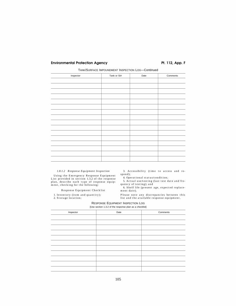
105
Environmental Protection Agency Pt. 112, App. F
TANK/SURFACE IMPOUNDMENT INSPECTION LOG—Continued
Inspector Tank or SI# Date Comments
1.8.1.2 Response Equipment Inspection
Using the Emergency Response Equipment List provided in section 1.3.2 of the response plan, describe each type of response equip-ment, checking for the following:
Response Equipment Checklist
1. Inventory (item and quantity); 2. Storage location;
3. Accessibility (time to access and re-spond);
4. Operational status/condition; 5. Actual use/testing (last test date and fre-
quency of testing); and 6. Shelf life (present age, expected replace-
ment date).
Please note any discrepancies between this list and the available response equipment.
RESPONSE EQUIPMENT INSPECTION LOG [Use section 1.3.2 of the response plan as a checklist]
Inspector Date Comments
VerDate Mar<15>2010 10:37 Jul 28, 2011 Jkt 223165 PO 00000 Frm 00115 Fmt 8010 Sfmt 8002 Y:\SGML\223165.XXX 223165wre
ier-
avile
s on
DS
KG
BLS
3C1P
RO
D w
ith C
FR

106
40 CFR Ch. I (7–1–11 Edition) Pt. 112, App. F
RESPONSE EQUIPMENT INSPECTION LOG—Continued [Use section 1.3.2 of the response plan as a checklist]
Inspector Date Comments
1.8.1.3 Secondary Containment Inspection
Inspect the secondary containment (as de-scribed in sections 1.4.1 and 1.7.2 of the re-sponse plan), checking the following:
Secondary Containment Checklist
1. Dike or berm system. A. Level of precipitation in dike/available
capacity; B. Operational status of drainage valves; C. Dike or berm permeability; D. Debris; E. Erosion; F. Permeability of the earthen floor of
diked area; and G. Location/status of pipes, inlets, drain-
age beneath tanks, etc. 2. Secondary containment
A. Cracks; B. Discoloration; C. Presence of spilled or leaked material
(standing liquid); D. Corrosion; and E. Valve conditions.
3. Retention and drainage ponds A. Erosion; B. Available capacity; C. Presence of spilled or leaked material; D. Debris; and E. Stressed vegetation.
The tank inspection checklist presented below has been included as guidance during inspections and monitoring. Similar require-ments exist in 40 CFR part 112, subparts A through C. Similar requirements exist in 40 CFR 112.7(e). Duplicate information from the SPCC Plan may be photocopied and inserted in this section.
1.8.2 Facility Drills/Exercises
(A) CWA section 311(j)(5), as amended by OPA, requires the response plan to contain a
description of facility drills/exercises. Ac-cording to 40 CFR 112.21(c), the facility owner or operator shall develop a program of facility response drills/exercises, including evaluation procedures. Following the PREP guidelines (see Appendix E to this part, sec-tion 13, for availability) would satisfy a fa-cility’s requirements for drills/exercises under this part. Alternately, under § 112.21(c), a facility owner or operator may develop a program that is not based on the PREP guidelines. Such a program is subject to ap-proval by the Regional Administrator based on the description of the program provided in the response plan.
(B) The PREP Guidelines specify that the facility conduct internal and external drills/ exercises. The internal exercises include: qualified individual notification drills, spill management team tabletop exercises, equip-ment deployment exercises, and unan-nounced exercises. External exercises in-clude Area Exercises. Credit for an Area or Facility-specific Exercise will be given to the facility for an actual response to a dis-charge in the area if the plan was utilized for response to the discharge and the objectives of the Exercise were met and were properly evaluated, documented, and self-certified.
(C) Section 112.20(h)(8)(ii) requires the fa-cility owner or operator to provide a descrip-tion of the drill/exercise program to be car-ried out under the response plan. Qualified Individual Notification Drill and Spill Man-agement Team Tabletop Drill logs shall be provided in sections 1.8.2.1 and 1.8.2.2, respec-tively. These logs may be included in the fa-cility response plan or kept as an annex to the facility response plan. See section 1.3.3 of this appendix for Equipment Deployment Drill Logs.
VerDate Mar<15>2010 10:37 Jul 28, 2011 Jkt 223165 PO 00000 Frm 00116 Fmt 8010 Sfmt 8002 Y:\SGML\223165.XXX 223165wre
ier-
avile
s on
DS
KG
BLS
3C1P
RO
D w
ith C
FR

107
Environmental Protection Agency Pt. 112, App. F
1.8.2.1 Qualified Individual Notification Drill Logs
Qualified Individual Notification Drill Log
Date: llllllllllllllllllll
Company: llllllllllllllllll
Qualified Individual(s): lllllllllll
Emergency Scenario: llllllllllll
llllllllllllllllllllllll
llllllllllllllllllllllll
Evaluation: lllllllllllllllll
llllllllllllllllllllllll
llllllllllllllllllllllll
llllllllllllllllllllllll
Changes to be Implemented: llllllll
llllllllllllllllllllllll
llllllllllllllllllllllll
Time Table for Implementation: llllll
llllllllllllllllllllllll
1.8.2.2 Spill Management Team Tabletop Exercise Logs
Spill Management Team Tabletop Exercise Log
Date: llllllllllllllllllll
Company: llllllllllllllllll
Qualified Individual(s): lllllllllll
Emergency Scenario: llllllllllll
llllllllllllllllllllllll
llllllllllllllllllllllll
Evaluation: lllllllllllllllll
llllllllllllllllllllllll
llllllllllllllllllllllll
llllllllllllllllllllllll
Changes to be Implemented: llllllll
llllllllllllllllllllllll
llllllllllllllllllllllll
Time Table for Implementation: llllll
1.8.3 Response Training
Section 112.21(a) requires facility owners or operators to develop programs for facility re-sponse training. Facility owners or operators are required by § 112.20(h)(8)(iii) to provide a description of the response training program to be carried out under the response plan. A facility’s training program can be based on the USCG’s Training Elements for Oil Spill Response, to the extent applicable to facility operations, or another response training pro-gram acceptable to the RA. The training ele-ments are available from the USCG Office of Response (G-MOR) at (202) 267–0518 or fax (202) 267–4085. Personnel response training logs and discharge prevention meeting logs shall be included in sections 1.8.3.1 and 1.8.3.2 of the response plan respectively. These logs may be included in the facility response plan or kept as an annex to the facility response plan.
1.8.3.1 Personnel Response Training Logs
PERSONNEL RESPONSE TRAINING LOG
Name Response training/date and number of hours
Prevention training/date and number of hours
1.8.3.2 Discharge Prevention Meetings Logs
DISCHARGE PREVENTION MEETING LOG
Date: llllllllllllllllllll
Attendees: llllllllllllllllll
llllllllllllllllllllllll
llllllllllllllllllllllll
llllllllllllllllllllllll
llllllllllllllllllllllll
llllllllllllllllllllllll
llllllllllllllllllllllll
llllllllllllllllllllllll
llllllllllllllllllllllll
VerDate Mar<15>2010 10:37 Jul 28, 2011 Jkt 223165 PO 00000 Frm 00117 Fmt 8010 Sfmt 8002 Y:\SGML\223165.XXX 223165wre
ier-
avile
s on
DS
KG
BLS
3C1P
RO
D w
ith C
FR

108
40 CFR Ch. I (7–1–11 Edition) Pt. 112, App. F
Subject/issue identified Required action Implementation date
1.9 Diagrams
The facility-specific response plan shall in-clude the following diagrams. Additional dia-grams that would aid in the development of response plan sections may also be included. (1) The Site Plan Diagram shall, as appro-
priate, include and identify: (A) the entire facility to scale; (B) above and below ground bulk oil stor-
age tanks; (C) the contents and capacities of bulk oil
storage tanks; (D) the contents and capacity of drum oil
storage areas; (E) the contents and capacities of surface
impoundments; (F) process buildings; (G) transfer areas; (H) secondary containment systems (loca-
tion and capacity); (I) structures where hazardous materials
are stored or handled, including mate-rials stored and capacity of storage;
(J) location of communication and emer-gency response equipment;
(K) location of electrical equipment which contains oil; and
(L) for complexes only, the interface(s) (i.e., valve or component) between the portion of the facility regulated by EPA and the portion(s) regulated by other Agencies. In most cases, this interface is defined as the last valve inside secondary containment before piping leaves the sec-ondary containment area to connect to the transportation-related portion of the facility (i.e., the structure used or in-tended to be used to transfer oil to or from a vessel or pipeline). In the absence of secondary containment, this interface is the valve manifold adjacent to the tank nearest the transfer structure as de-scribed above. The interface may be de-fined differently at a specific facility if agreed to by the RA and the appropriate Federal official.
(2) The Site Drainage Plan Diagram shall, as appropriate, include:
(A) major sanitary and storm sewers, man-holes, and drains;
(B) weirs and shut-off valves; (C) surface water receiving streams; (D) fire fighting water sources; (E) other utilities; (F) response personnel ingress and egress; (G) response equipment transportation
routes; and (H) direction of discharge flow from dis-
charge points. (3) The Site Evacuation Plan Diagram shall,
as appropriate, include: (A) site plan diagram with evacuation
route(s); and (B) location of evacuation regrouping
areas.
1.10 Security
According to 40 CFR 112.7(g) facilities are required to maintain a certain level of secu-rity, as appropriate. In this section, a de-scription of the facility security shall be pro-vided and include, as appropriate: (1) emergency cut-off locations (automatic
or manual valves); (2) enclosures (e.g., fencing, etc.); (3) guards and their duties, day and night; (4) lighting; (5) valve and pump locks; and (6) pipeline connection caps. The SPCC Plan contains similar informa-tion. Duplicate information may be photocopied and inserted in this section.
2.0 Response Plan Cover Sheet
A three-page form has been developed to be completed and submitted to the RA by own-ers or operators who are required to prepare and submit a facility-specific response plan. The cover sheet (Attachment F–1) must ac-company the response plan to provide the Agency with basic information concerning the facility. This section will describe the Response Plan Cover Sheet and provide in-structions for its completion.
2.1 General Information
Owner/Operator of Facility: Enter the name of the owner of the facility (if the owner is the operator). Enter the operator of the fa-cility if otherwise. If the owner/operator of
VerDate Mar<15>2010 10:37 Jul 28, 2011 Jkt 223165 PO 00000 Frm 00118 Fmt 8010 Sfmt 8002 Y:\SGML\223165.XXX 223165wre
ier-
avile
s on
DS
KG
BLS
3C1P
RO
D w
ith C
FR
109
Environmental Protection Agency Pt. 112, App. F
the facility is a corporation, enter the name of the facility’s principal corporate execu-tive. Enter as much of the name as will fit in each section.
(1) Facility Name: Enter the proper name of the facility.
(2) Facility Address: Enter the street ad-dress, city, State, and zip code.
(3) Facility Phone Number: Enter the phone number of the facility.
(4) Latitude and Longitude: Enter the facil-ity latitude and longitude in degrees, min-utes, and seconds.
(5) Dun and Bradstreet Number: Enter the facility’s Dun and Bradstreet number if available (this information may be obtained from public library resources).
(6) North American Industrial Classifica-tion System (NAICS) Code: Enter the facili-ty’s NAICS code as determined by the Office of Management and Budget (this information may be obtained from public library re-sources.)
(7) Largest Oil Storage Tank Capacity: Enter the capacity in GALLONS of the largest aboveground oil storage tank at the facility.
(8) Maximum Oil Storage Capacity: Enter the total maximum capacity in GALLONS of all aboveground oil storage tanks at the facil-ity.
(9) Number of Oil Storage Tanks: Enter the number of all aboveground oil storage tanks at the facility.
(10) Worst Case Discharge Amount: Using in-formation from the worksheets in Appendix D, enter the amount of the worst case dis-charge in GALLONS.
(11) Facility Distance to Navigable Waters: Mark the appropriate line for the nearest distance between an opportunity for dis-charge (i.e., oil storage tank, piping, or flowline) and a navigable water.
2.2 Applicability of Substantial Harm Criteria
Using the flowchart provided in Attach-ment C–I to Appendix C to this part, mark the appropriate answer to each question. Ex-planations of referenced terms can be found in Appendix C to this part. If a comparable formula to the ones described in Attachment C–III to Appendix C to this part is used to calculate the planning distance, documenta-tion of the reliability and analytical sound-ness of the formula must be attached to the response plan cover sheet.
2.3 Certification
Complete this block after all other ques-tions have been answered.
3.0 Acronyms
ACP: Area Contingency Plan ASTM: American Society of Testing Mate-
rials bbls: Barrels bpd: Barrels per Day
bph: Barrels per Hour CHRIS: Chemical Hazards Response Informa-
tion System CWA: Clean Water Act DOI: Department of Interior DOC: Department of Commerce DOT: Department of Transportation EPA: Environmental Protection Agency FEMA: Federal Emergency Management
Agency FR: Federal Register gal: Gallons gpm: Gallons per Minute HAZMAT: Hazardous Materials LEPC: Local Emergency Planning Com-
mittee MMS: Minerals Management Service (part of
DOI) NAICS: North American Industrial Classi-
fication System NCP: National Oil and Hazardous Substances
Pollution Contingency Plan NOAA: National Oceanic and Atmospheric
Administration (part of DOC) NRC: National Response Center NRT: National Response Team OPA: Oil Pollution Act of 1990 OSC: On-Scene Coordinator PREP: National Preparedness for Response
Exercise Program RA: Regional Administrator RCRA: Resource Conservation and Recovery
Act RRC: Regional Response Centers RRT: Regional Response Team RSPA: Research and Special Programs Ad-
ministration SARA: Superfund Amendments and Reau-
thorization Act SERC: State Emergency Response Commis-
sion SDWA: Safe Drinking Water Act of 1986 SI: Surface Impoundment SPCC: Spill Prevention, Control, and Coun-
termeasures USCG: United States Coast Guard
4.0 References
CONCAWE. 1982. Methodologies for Hazard Analysis and Risk Assessment in the Petro-leum Refining and Storage Industry. Pre-pared by CONCAWE’s Risk Assessment Ad- hoc Group.
U.S. Department of Housing and Urban De-velopment. 1987. Siting of HUD-Assisted Projects Near Hazardous Facilities: Accept-able Separation Distances from Explosive and Flammable Hazards. Prepared by the Of-fice of Environment and Energy, Environ-mental Planning Division, Department of Housing and Urban Development. Wash-ington, DC.
U.S. DOT, FEMA and U.S. EPA. Handbook of Chemical Hazard Analysis Procedures.
U.S. DOT, FEMA and U.S. EPA. Technical Guidance for Hazards Analysis: Emergency
VerDate Mar<15>2010 10:37 Jul 28, 2011 Jkt 223165 PO 00000 Frm 00119 Fmt 8010 Sfmt 8002 Y:\SGML\223165.XXX 223165wre
ier-
avile
s on
DS
KG
BLS
3C1P
RO
D w
ith C
FR

110
40 CFR Ch. I (7–1–11 Edition) Pt. 112, App. F
1 These numbers may be obtained from pub-lic library resources.
2 Explanations of the above-referenced terms can be found in Appendix C to this part. If a comparable formula to the ones contained in Attachment C–III is used to es-tablish the appropriate distance to fish and wildlife and sensitive environments or public drinking water intakes, documentation of the reliability and analytical soundness of the formula must be attached to this form.
3 For further description of fish and wildlife and sensitive environments, see Appendices I, II, and III to DOC/NOAA’s ‘‘Guidance for Facility and Vessel Response Plans: Fish and Wildlife and Sensitive Environments’’ (see Appendix E to this part, section 13, for avail-ability) and the applicable ACP.
Planning for Extremely Hazardous Sub-stances.
The National Response Team. 1987. Haz-ardous Materials Emergency Planning Guide. Washington, DC.
The National Response Team. 1990. Oil Spill Contingency Planning, National Sta-tus: A Report to the President. Washington, DC. U.S. Government Printing Office.
Offshore Inspection and Enforcement Divi-sion. 1988. Minerals Management Service, Offshore Inspection Program: National Po-tential Incident of Noncompliance (PINC) List. Reston, VA.
ATTACHMENTS TO APPENDIX F
Attachment F–1—Response Plan Cover Sheet
This cover sheet will provide EPA with basic information concerning the facility. It must accompany a submitted facility re-sponse plan. Explanations and detailed in-structions can be found in Appendix F. Please type or write legibly in blue or black ink. Public reporting burden for the collec-tion of this information is estimated to vary from 1 hour to 270 hours per response in the first year, with an average of 5 hours per re-sponse. This estimate includes time for re-viewing instructions, searching existing data sources, gathering the data needed, and com-pleting and reviewing the collection of infor-mation. Send comments regarding the bur-den estimate of this information, including suggestions for reducing this burden to: Chief, Information Policy Branch, Mail Code: PM–2822, U.S. Environmental Protection Agency, Ariel Rios Building, 1200 Pennsyl-vania Avenue, NW., Washington, DC 20460; and to the Office of Information and Regu-latory Affairs, Office of Management and Budget, Washington D.C. 20503.
GENERAL INFORMATION
Owner/Operator of Facility: lllllllll
llllllllllllllllllllllll
Facility Name: lllllllllllllll
Facility Address (street address or route): llllllllllllllllllllllll
City, State, and U.S. Zip Code: lllllll
Facility Phone No.: lllllllllllll
Latitude (Degrees: North):
llllllllllllllllllllllll
degrees, minutes, seconds
Dun & Bradstreet Number: 1 llllllll
Largest Aboveground Oil Storage Tank Ca-pacity (Gallons): lllllllllllll
Number of Aboveground Oil Storage Tanks:
Longitude (Degrees: West):
llllllllllllllllllllllll
degrees, minutes, seconds llllllllll
North American Industrial Classification System (NAICS) Code: 1 llllllllll
Maximum Oil Storage Capacity (Gallons): l
Worst Case Oil Discharge Amount (Gallons): llllllllllllllllllllllll
Facility Distance to Navigable Water. Mark the appropriate line. lllllllllll
0–1⁄4 mile ll
1⁄4–1⁄2 mile ll
1⁄2–1 mile ll >1 mile ll
APPLICABILITY OF SUBSTANTIAL HARM CRITERIA
Does the facility transfer oil over-water 2 to or from vessels and does the facility have a total oil storage capacity greater than or equal to 42,000 gallons? Yes lllllllllllllllllllll
No llllllllllllllllllllll
Does the facility have a total oil storage capacity greater than or equal to 1 million gallons and, within any storage area, does the facility lack secondary containment 2 that is sufficiently large to contain the ca-pacity of the largest aboveground oil storage tank plus sufficient freeboard to allow for precipitation?
Yes lllllllllllllllllllll
No llllllllllllllllllllll
Does the facility have a total oil storage capacity greater than or equal to 1 million gallons and is the facility located at a dis-tance 2 (as calculated using the appropriate formula in Appendix C or a comparable for-mula) such that a discharge from the facility could cause injury to fish and wildlife and sensitive environments? 3
Yes lllllllllllllllllllll
No llllllllllllllllllllll
VerDate Mar<15>2010 10:37 Jul 28, 2011 Jkt 223165 PO 00000 Frm 00120 Fmt 8010 Sfmt 8002 Y:\SGML\223165.XXX 223165wre
ier-
avile
s on
DS
KG
BLS
3C1P
RO
D w
ith C
FR
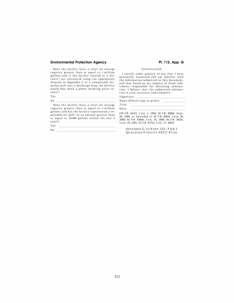
111
Environmental Protection Agency Pt. 112, App. G
Does the facility have a total oil storage capacity greater than or equal to 1 million gallons and is the facility located at a dis-tance 2 (as calculated using the appropriate formula in Appendix C or a comparable for-mula) such that a discharge from the facility would shut down a public drinking water in-take? 2
Yes lllllllllllllllllllll
No llllllllllllllllllllll
Does the facility have a total oil storage capacity greater than or equal to 1 million gallons and has the facility experienced a re-portable oil spill 2 in an amount greater than or equal to 10,000 gallons within the last 5 years?
Yes lllllllllllllllllllll
No llllllllllllllllllllll
CERTIFICATION
I certify under penalty of law that I have personally examined and am familiar with the information submitted in this document, and that based on my inquiry of those indi-viduals responsible for obtaining informa-tion, I believe that the submitted informa-tion is true, accurate, and complete.
Signature: llllllllllllllllll
Name (Please type or print): llllllll
Title: llllllllllllllllllll
Date: llllllllllllllllllll
[59 FR 34122, July 1, 1994; 59 FR 49006, Sept. 26, 1994, as amended at 65 FR 40816, June 30, 2000; 65 FR 43840, July 14, 2000; 66 FR 34561, June 29, 2001; 67 FR 47152, July 17, 2002]
APPENDIX G TO PART 112—TIER I QUALIFIED FACILITY SPCC PLAN
VerDate Mar<15>2010 10:37 Jul 28, 2011 Jkt 223165 PO 00000 Frm 00121 Fmt 8010 Sfmt 8002 Y:\SGML\223165.XXX 223165wre
ier-
avile
s on
DS
KG
BLS
3C1P
RO
D w
ith C
FR

SPCC Plan Waco, TX
H:\T\ICUT-Texas Independent College\_TX Colleges\Baylor University\2015 SPCC Plan Update\Final\Baylor University SPCC Update 2015.docx
APPENDIX B SPCC PLAN REGULATORY CROSS
REFERENCE

SPCC Plan Waco, TX
H:\T\ICUT-Texas Independent College\_TX Colleges\Baylor University\2015 SPCC Plan Update\Final\Baylor University SPCC Update 2015.docx
Baylor University SPCC Plan Regulatory Cross Reference
SPCC Rule Section Description
Facility SPCC Plan
Visually Confirmed
in Field
112.3(d) Except as provided in § 112.6, a licensed Professional Engineer must review and certify a Plan for it to be effective to satisfy the requirements of this part. I NA
112.3(d)(1) By means of this certification the Professional Engineer attests: i NA 112.3(d)(1)(i) That he is familiar with the requirements of this part: i NA 112.3(d)(1)(ii) That he or his agent has visited and examined the facility: i NA 112.3(d)(1)(iii)
That the Plan has been prepared in accordance with good engineering practice, including consideration of applicable industry standards, and with the requirements of this part; i NA
112.3(d)(1)(iv)
That procedures for required inspections and testing have been established; and i NA
112.3(d)(1)(v) That the Plan is adequate for the facility. I NA 112.3(d)(1)(vi)
That, if applicable, for a produced water container subject to § 112.9I(6), any procedure to minimize the amount of free-phase oil is designed to reduce the accumulation of free-phase oil and the procedures and frequency for required inspections, maintenance and testing have been established and are described in the Plan.
NA
NA
112.4(a) Notwithstanding compliance with § 112.3, whenever your facility has discharged more than 1,000 U.S. gallons of oil in a single discharge as described in § 112.1(b), or discharged more than 42 U.S. gallons of oil in each of two discharges as described in § 112.1(b), occurring within any twelve month period, submit the following information to the Regional Administrator within 60 days from the time the facility becomes subject of this section:
§3.4
NA
112.4(a)(1) Name of the facility; §3.4 NA 112.4(a)(2) Your name; §3.4 NA 112.4(a)(3) Location of the facility; §3.4 NA 112.4(a)(4) Maximum storage or handling capacity of the facility and normal daily throughput; §3.4 NA 112.4(a)(5) Corrective action and countermeasures you have taken, including a description of
equipment repairs and replacements; §3.4 NA
112.4(a)(6) An adequate description of the facility, including maps, flow diagrams, and topographical maps, as necessary; §3.4 NA
112.4(a)(7) The cause of such discharge as described in § 112.1(b), including a failure analysis of the system or subsystem in which the failure occurred; §3.4 NA
112.4(a)(8) An additional preventive measures you have taken or contemplated to minimize the possibility of recurrence; and §3.4 NA
112.4(a)(9) Such other information as the Regional Administrator may reasonably require pertinent to the Plan or discharge. §3.4 NA
112.4(d) Amendment of Spill Prevention Control and Countermeasure Plan (SPCC) by Regional Administrator. -- --
112.5(a) SPCC amendments due to changes in facility design. Iii NA 112.5(b) Perform a review and evaluation of SPCC Plan at least once every five years. The
owner/operator must document completion of the review and evaluation, and must sign a statement as to whether he will amend the SPCC Plan. The following will suffice: “I have completed review and evaluation of the SPCC Plan for (name of facility) on (date), and will (will not) amend the Plan as a result.
Iii
NA
112.5I Obtain Professional Engineers certification for any technical amendments in accordance with 11-2.3(d). iii NA
112.7(a)(1) Include a discussion of your facility’s conformance with the requirements listed in 40 CFR 112.7. -- --

SPCC Plan Waco, TX
H:\T\ICUT-Texas Independent College\_TX Colleges\Baylor University\2015 SPCC Plan Update\Final\Baylor University SPCC Update 2015.docx
Baylor University SPCC Plan Regulatory Cross Reference
SPCC Rule Section Description
Facility SPCC Plan
Visually Confirmed
in Field
112.7(a)(2) Comply with all applicable requirements listed in this part. Except as provided in § 112.6, your Plan may deviate from the requirements in paragraphs (g), (h)(2) and (3), and (i) of this section and the requirements in subparts B and C of this part, except the secondary containment requirements in paragraphs I and (h)(1) of this section, and §§ 112.8I(2), 112.8I(11), 112.9I(2), 112.9(d)(3), 112.10I, 112.12I(2), and 112.12I(11), where applicable to a specific facility, if you provide equivalent environmental protection by some other means of spill prevention, control, or countermeasure. Where your Plan does not conform to the applicable requirements in paragraphs (g), (h)(2) and (3), and (i) of this section, or the requirements of subparts B and C of this part, except the secondary containment requirements in paragraph I and (h)(1) of this section, and §§ 112.8I(2), 112.8I(11), 112.9I(2), 112.10I, 112.12I(2), and 112.12I(11), you must state the reasons for nonconformance in your Plan and describe in detail alternate methods and how you will achieve equivalent environmental protection. If the Regional Administrator determines that the measures described in your Plan do not provide equivalent environmental protection, he may require that you amend your Plan, following the procedures in § 112.4(d) and (e).
§6.3.1
112.7(a)(3) Describe in your Plan the physical layout of the facility and include a facility diagram, which must mark the location and contents of each fixed oil storage container and the storage area where mobile or portable containers are located. The facility diagram must identify the location of and mark as “exempt” underground tanks that are otherwise exempted from the requirements of this part under § 112.1(d)(4). The facility diagram must also include all transfer stations and connecting pipes, including intra-facility gathering lines that are otherwise exempted from the requirements of this part under § 112.1(d)(11). You must also address in your Plan:
Figures 1 and 2, Table 1
112.7(a)(3)(i) The type of oil in each fixed container and its storage capacity. For mobile or portable containers, either provide the type of oil and storage capacity for each container or provide an estimate of the potential number of mobile or portable containers, the types of oil, and anticipated storage capacities
Table 1
112.7(a)(3)(ii) (ii) Discharge prevention measures including procedures for routine handling of products (loading, unloading, and facility transfers, etc.); §6
112.7(a)(3)(iii)
(iii) Discharge or drainage controls such as secondary containment around containers and other structures, equipment, and procedures for the control of a discharge. §6
112.7(a)(3)(iv)
(iv) Countermeasures for discharge discovery, response, and cleanup (both the facility’s capability and those that might be required of a contractor); §3
112.7(a)(3)(v) (v) Methods of disposal of recovered materials in accordance with applicable legal requirements; and §6.3.3
112.7(a)(3)(vi)
(vi) Contact list and phone numbers for the facility response coordinator, National Response Center, cleanup contractors with whom you have an agreement for response, and all appropriate Federal, State, and local agencies who must be contacted in case of discharge as described in § 112.1(b).
§3 & 4
112.7(a)(4) Unless you have submitted a response plan under 40 CFR 112.20, provide information and procedures in your SPCC Plan to enable a person reporting a discharge to relate information on the exact address or location and phone number of the facility…
§3 & 4
112.7(a)(5) Unless you have submitted a response plan under 40 CFR 112.20, organize portions of the SPCC Plan describing procedures you will use when a discharge occurs in a way that will make them readily usable in an emergency and include appropriate supporting materials as appendices.
§3 & 4
112.7(b) Where experience indicates a reasonable potential for equipment failure (such as loading or unloading equipment, tank overflow, rupture, or leakage, or any other equipment known to be a source of a discharge), include in your Plan a prediction of the direction, rate of flow, and total quantity of oil which could be discharged from the facility as a result of each type of major equipment failure.
Table 1

SPCC Plan Waco, TX
H:\T\ICUT-Texas Independent College\_TX Colleges\Baylor University\2015 SPCC Plan Update\Final\Baylor University SPCC Update 2015.docx
Baylor University SPCC Plan Regulatory Cross Reference
SPCC Rule Section Description
Facility SPCC Plan
Visually Confirmed
in Field
112.7I Provide appropriate containment and/or diversionary structures or equipment to prevent a discharge as described in § 112.1(b), except as provided in paragraph (k) of this section for qualified oil-filled operational equipment, and except as provided in § 112.9(d)(3) for flowlines and intra-facility gathering lines at an oil production facility. The entire containment system, including walls and floor, must be capable of containing oil and must be constructed so that any discharge from a primary containment system, such as a tank, will not escape the containment system before cleanup occurs. In determining the method, design, and capacity for secondary containment, you need only to address the typical failure mode, and the most likely quantity of oil that would be discharged. Secondary containment may be either active or passive in design. At a minimum, you must use one of the following prevention systems or its equivalent:
§6
112.7I(1) For onshore facilities: Section T. Dikes, berms, or retaining walls sufficiently impervious to contain oil; (ii) Curbing or drip pans; (iii) Sumps and collection systems; (iv) Culverting, gutters, or other drainage systems; (v) Weirs, booms, or other barriers; (vi) Spill diversion ponds; (vii) Retention ponds; or (viii) Sorbent materials.
§6
112.7I(2) For offshore facilities: Section T. Curbing or drip pans; or (ii) Sumps and collection systems.
NA NA
112.7(d) When installation of structures or equipment, as outlined in 112.7I and (h)(1) and 40 CFR 112.8I(2), I(11), 112.9I(2), 112.10I, 112.12I(2), 112.12I(11), 112.13I(2) and 112.14I is not practicable, clearly explain why such measures are not practicable; for bulk storage containers, conduct periodic integrity testing of the containers and periodic integrity and leak testing of the valves and piping, unless you have submitted a response plan under 40 CFR 112.20 provide the following in your SPCC Plan:
1. Provide an oil spill contingency plan described in 40 CFR 109; and 2. Provide a written commitment of manpower, equipment, and materials to control and remove harmful quantity of oil discharged.
§6.2 §13
112.7(e) Conduct inspections and tests required by this part in accordance with written procedures that you or the certifying engineer developed for the facility. You must keep these written procedures and a record of the inspections and tests, signed by the appropriate supervisor or inspector, with the SPCC Plan for a period of three years. Records of inspections and tests kept under usual and customary business practices will suffice for purposes of this paragraph.
§7
112.7(f) Personnel, training, and discharge prevention procedures -- -- 112.7(f)(1) At a minimum, train your oil-handling personnel in the operation and maintenance of
equipment to prevent discharges; discharge procedure protocols; applicable pollution control laws, rule, and regulations; general facility operations; and, the contents of the facility SPCC Plan.
§10
112.7(f)(2) Designate a person at each applicable facility who is accountable for discharge prevention and who reports to facility management. §10
112.7(f)(3) Schedule and conduct discharge prevention briefings for your oil handling personnel at least once a year to assure adequate understanding of the SPCC Plan for that facility. Such briefings must highlight and describe known discharges as described in § 112.1(b) or failures, malfunctioning components, and any recently developed precautionary measures.
§10
112.7(g) Security (excluding oil production facilities). Describe in your Plan how you secure and control access to the oil handling, processing and storage areas; secure master flow and drain valves; prevent unauthorized access to starter controls on oil pumps; secure out-of-service and loading/unloading connections of oil pipelines; and address the appropriateness of security lighting to both prevent acts of vandalism and assist in the discovery of oil discharges.
§9
112.7(h) Facility tank car and tank truck loading/unloading rack (excluding offshore facilities). -- --

SPCC Plan Waco, TX
H:\T\ICUT-Texas Independent College\_TX Colleges\Baylor University\2015 SPCC Plan Update\Final\Baylor University SPCC Update 2015.docx
Baylor University SPCC Plan Regulatory Cross Reference
SPCC Rule Section Description
Facility SPCC Plan
Visually Confirmed
in Field
112.7(h)(1) Where loading/unloading rack drainage does not flow into a catchment basin or treatment facility designed to handle discharges, use a quick drainage system for tank car or tank truck loading/unloading racks. You must design any containment system to hold at least the maximum capacity of any single compartment of a tank car or tank truck loaded or unloaded at the facility.
§6
112.7(h)(2) Provide an interlocked warning light or physical barrier system, warning signs, wheel chocks, or vehicle break interlock system in loading/unloading areas to prevent vehicles from departing before complete disconnection of flexible or fixed oil transfer lines.
§6
112.7(h)(3) Prior to filling and department of any tank car or tank truck, closely inspect for discharges the lowermost drain and all outlets of such vehicles, and if necessary, ensure that they are tightened, adjusted, or replaced to prevent liquid discharge while in transit.
§6
112.7(i) If a field-constructed aboveground container undergoes a repair, alteration, reconstruction or a change in service that might affect the risk of a discharge or failure due to brittle fracture or other catastrophe, or has discharged oil or failed due to brittle fracture failure or other catastrophe, evaluate the container of risk of discharge or failure due to brittle fracture or other catastrophe, and as necessary, take appropriate action.
7.0
112.7(j) In addition to the minimal prevention standards listed under this section, include in your Plan a complete discussion of conformance with the applicable requirements and other effective discharge prevention and containment procedures listed in this part or any applicable more stringent State rules, regulations, and guidelines.
NA
112.8(b), 112.12(b)
Facility Drainage (for onshore facilities, except oil production) -- --
112.8 (b)(1), 112.12 (b)(1)
Restrain drainage from diked storage areas by valves to prevent a discharge into the drainage system or facility effluent treatment system, except where facility systems are designed to control such discharge. You may empty diked areas by pumps or ejectors; however, you must manually activate these pumps or ejectors and must inspect the condition of the accumulation before starting, to ensure no oil will be discharged.
6.3.2
112.8 (b)(2), 112.12 (b)(2)
Use valves of manual, open-and-closed design, for the drainage of diked areas. You may not use flapper-type drain valves to drain diked areas. If your facility drainage drains directly into a watercourse and not into an on-site wastewater treatment plant, you must inspect and may drain uncontaminated retained storm water, as provided in paragraphs I(3)(ii), (iii), and (iv) of this section.
6.3.2
112.8 (b)(3), 112.12 (b)(3)
Design facility drainage systems from undiked areas with a potential for a discharge (such as where piping is located outside containment walls or where tank truck discharges may occur outside the loading area) to flow into ponds, lagoons, or catchment basins designed to retain oil or return it to the facility. You must not locate catchment basins in areas subject to periodic flooding.
6.3
112.8 (b)(4), 112.12 (b)(4)
If facility drainage is not engineered as in paragraph (b)(3) of this section, equip the final discharge of all ditches inside the facility with a diversion system that would, in the event of an uncontrolled discharge retain oil in the facility.
6.3
112.8 (b)(5), 112.12 (b)(5)
Where drainage waters are treated in more than one treatment unit and such treatment is continuous, and pump transfer is needed, provide two “lift” pumps and permanently install at least one of the pumps. Whatever techniques you use, you must engineer facility drainage systems to prevent a discharge as described in § 112.1(b) in case there is an equipment failure or human error at the facility.
NA
112.8 I, 112.12 I
Bulk Storage Containers (for onshore facilities, except oil production) -- --
112.8 I(1), 112.12 I(1)
Bulk storage containers. (1) Not use a container for the storage of oil unless its material and construction are compatible with the material stored and conditions of storage such as pressure and temperature.
6.1
112.8 I(2), 112.12 I(2)
Construct all bulk storage tank installations (except mobile refuelers and other non-transportation-related tank trucks) so that you provide a secondary means of containment for the entire capacity of the largest single container and sufficient freeboard to contain precipitation. You must ensure that diked areas are sufficiently impervious to contain discharged oil. Dikes, containment curbs, and pits are commonly employed for this purpose. You may also use an alternative system consisting of a drainage trench enclosure that must be arranged so that any discharge will terminate and be safely confined in a facility catchment basin or holding pond.
§6

SPCC Plan Waco, TX
H:\T\ICUT-Texas Independent College\_TX Colleges\Baylor University\2015 SPCC Plan Update\Final\Baylor University SPCC Update 2015.docx
Baylor University SPCC Plan Regulatory Cross Reference
SPCC Rule Section Description
Facility SPCC Plan
Visually Confirmed
in Field
112.8 I(3), 112.12 I(3)
Not allow drainage of uncontaminated rainwater from the diked area into a storm drain or discharge of an effluent into an open watercourse, lake, or pond, bypassing the facility treatment system unless you:
(i) Normally keep the bypass valve sealed closed. (ii) Inspect the retained rainwater to ensure that its presence will not cause a
discharge as described in § 112.1(b). (iii) Open the bypass valve and reseal it following drainage under responsible
supervision; and (iv) Keep adequate records of such events, for example, any records required
under permits issued in accordance with §§ 122.41 (j)(2) and 122.41 (m)(3).
6.3.2
112.8 I(4) Protect any completely buried metallic storage tank installed on or after January 10, 1974 from corrosion by coatings or cathodic protection compatible with local soil conditions. You must regularly leak test such completely buried metallic storage tanks.
NA
112.8I(5) Do not use partially buried or bunkered metallic tanks for the storage of oil, unless you protect the buried section of the tank from corrosion. You must protect partially buried and bunkered tanks from corrosion by coatings or cathodic protection compatible with local soil conditions.
NA
112.8I(6) Test or inspect each aboveground container for integrity on a regular schedule and whenever you make material repairs. You must determine, in accordance with industry standards, the appropriate qualifications for personnel performing tests and inspections, the frequency and type of testing and inspections, which take into account container size, configuration, and design (such as containers that are: shop-built, field-erected, skid-mounted, elevated, equipped with a liner, double-walled, or partially buried). Examples of these integrity tests include, but are not limited to: visual inspection, hydrostatic testing, radiographic testing, ultrasonic testing, acoustic emissions testing, or other systems of non-destructive testing. You must keep comparison records and you must also inspect the container’s supports and foundations. In addition, you must frequently inspect the outside of the container for signs of deterioration, discharges, or accumulation of oil inside diked areas. Records of inspections and tests kept under usual and customary business practices satisfy the recordkeeping requirements of this paragraph.
7.3
112.8I(7) Control leakage through defective internal heating coils by monitoring the steam return and exhaust lines for contamination from internal heating coils that discharge into an open watercourse, or pass the steam return or exhaust lines through a settling tank, skimmer, or other separation or retention system.
NA
112.8I(8) Engineer or update each container installation in accordance with good engineering practice to avoid discharges. You must provide at least one of the following devices:
(i) High liquid level alarms with an audible or visual signal at a constantly attended operation or surveillance station. In smaller facilities, an audible air vent may suffice.
(ii) High liquid level pump cutoff devices set to stop flow at a predetermined container content level.
(iii) Direct communication between tank gauger and pumping station. (iv) Fast response system for determining liquid level of each bulk storage
container such as digital computers, telepulse, or direct vision gauges. If you use this alternative, a person must be present to monitor gauges and the overall filling of bulk storage containers.
(v) You must regularly test liquid level sensing devices to ensure proper operation.
Table 1 and §6
112.8I(9) Observe effluent treatment facilities frequently enough to detect possible system upsets that could cause a discharge as described in § 112.1(b). NA
112.8I(10) Promptly correct visible discharges which result in a loss of oil from the container, including but not limited to seams, gaskets, piping, pumps, valves, rivets, and bolts. You must promptly remove any accumulations of oil in diked areas.
§4 §6
112.8I(11) Position or locate mobile or portable oil storage containers to prevent a discharge as described in § 112.1(b). Except for mobile refuelers and other non-transportation-related tank trucks, you must furnish a secondary means of containment, such as a dike or catchment basin, sufficient to contain the capacity of the largest single compartment or container with sufficient freeboard to contain precipitation.
§6

SPCC Plan Waco, TX
H:\T\ICUT-Texas Independent College\_TX Colleges\Baylor University\2015 SPCC Plan Update\Final\Baylor University SPCC Update 2015.docx
Baylor University SPCC Plan Regulatory Cross Reference
SPCC Rule Section Description
Facility SPCC Plan
Visually Confirmed
in Field
112.8(d)(1) Facility Transfer Operations, Pumping, and Facility Process (onshore facilities, except oil production) -- --
112.8(d)(1) Provide buried piping that is installed or replaced on or after August 16, 2002, with a protective wrapping and coating. You must also cathodically protect such buried piping installations or otherwise satisfy the corrosion protection standards for piping in part 280 of this chapter or a State program approved under part 281 of this chapter. If a section of buried line is exposed for any reason, you must carefully inspect if for deterioration. If you find corrosion damage, you must undertake additional examination and corrective action as indicated by the magnitude of the damage.
NA
112.8(d)(2) Cap or blank-flange the terminal connection at the transfer point and mark it as to origin when piping is not in service or is in standby service for an extended time. NA
112.8(d)(3) Properly design pipe supports to minimize abrasion and corrosion and allow for expansion and contraction. §6
112.8(d)(4) Regularly inspect all aboveground valves, piping, and appurtenances. During the inspection you must assess the general condition of items, such as flange joints, expansion joints, valve glands and bodies, catch pans, pipeline supports, locking of valves, and metal surfaces. You must also conduct integrity and leak testing of buried piping at the time of installation, modification, construction, relocation, or replacement.
§7
112.8(d)(5) Warn all vehicles entering the facility to be sure that no vehicle will endanger aboveground piping or other oil transfer operations. §6.3.4
Appendix C to Part 112
Appendix C to Part 112 – Substantial Harm Criteria Section 2.1 A non-transportation-related facility with a total oil storage capacity greater than or equal to 42,000 gallons that transfers oil over water to or from vessels must submit a response plan to EPA. Section 2.2 Any facility with a total oil storage capacity greater than or equal to 1 million gallons without secondary containment sufficiently large to contain the capacity of the largest aboveground oil storage tank within each area plus sufficient freeboard to allow for precipitation must submit a response plan to the EPA. Secondary containment structures that meet the standard of good engineering practice for the purposes of this part include berms, dikes, retaining walls, curbing, culverts, gutters, or other drainage systems. Section 2.3 A facility with a total oil storage capacity greater than or equal to 1 million gallons must submit its response plan if it is located at a distance such that a discharge from the facility could cause injury (as defined by 40 CFR 112.2) to fish and wildlife sensitive environments, see Appendices I, II, and III to DOC/NOAA’s “Guidance for Facility and Vessel Response Plans: Fish and Wildlife and Sensitive Environments” (59 FR 14713, March 29, 1994) and the applicable Area Contingency Plan. Facility owners or operators must determine the distance at which an oil spill could cause the appropriate formula presented in Attachment C-III to this appendix or a comparable formula. Section 2.4 A facility with a total oil storage capacity greater than or equal to 1 million gallons must submit its response plan if it is located at a distance such that a discharge from the facility would shut down a public drinking water intake, which is analogous to a public water system as described at 40 CFR 143.2I.
Appendix E
The following sections of the SPCC Rules do not apply to the facility: 112.9 SPCC Plan requirements for onshore oil production facilities. 112.10 SPCC Plan requirements for onshore oil drilling and work over facilities. 112.11 SPCC Plan requirements for offshore oil drilling, production, or work over facilities.

SPCC Plan Waco, TX
H:\T\ICUT-Texas Independent College\_TX Colleges\Baylor University\2015 SPCC Plan Update\Final\Baylor University SPCC Update 2015.docx
APPENDIX C SPILL REPORTING FORM (EXAMPLE)

SPCC Plan Waco, TX
H:\T\ICUT-Texas Independent College\_TX Colleges\Baylor University\2015 SPCC Plan Update\Final\Baylor University SPCC Update 2015.docx
REPORT OF PETROLEUM
DISCHARGE, SPILLAGE, OR RELEASE
When did the incident occur? Date Time Where did the incident occur? How did the incident occur? What and how much spilled? Is there a reportable quantity (RQ) associated with the material and was that RQ exceeded? (reference the List of Lists) Describe path of spill and any affected water bodies or areas of the environment. If fully contained, described how the spill was contained to prevent a release. Under whose control was the product at the time of the incident? Please give their name, mailing address and telephone number (if not part of Baylor University). List agencies that were notified as a result of this spill or note “NA” if reporting not required per Section 3.3 of SPCC Plan: Date Time Person Making Notification Agency Notified Notes From
Conversation/Notification
What actions are being taken, or are proposed, to prevent reoccurrence of an incident of this type? Were there any injuries as a result of this incident? If so, list the names of exposed individuals, their addresses, phone numbers, and describe their injuries. What is the appropriate advice regarding medical attention necessary for exposed individuals? Are there any known or anticipated health risks, acute or chronic, associated with the release of this chemical or medical advice that should be communicated? What waste was generated as a result of clean-up activities and how was it dispose (provide waste classification and name of waste vendor)

SPCC Plan Waco, TX
H:\T\ICUT-Texas Independent College\_TX Colleges\Baylor University\2015 SPCC Plan Update\Final\Baylor University SPCC Update 2015.docx
I hereby affirm that the foregoing statement is true to the best of my knowledge. Signature Title Date Print Name Telephone Number Street Address/P.O. Box City/Town State Zip This form may be reproduced or computerized as long as it contains all of the information requested and is on an 8-1/2" x 11" white paper, black type format. For serious incidents the questions may be answered in a narrative format which must include the preparer’s affidavit.

SPCC Plan Waco, TX
H:\T\ICUT-Texas Independent College\_TX Colleges\Baylor University\2015 SPCC Plan Update\Final\Baylor University SPCC Update 2015.docx
APPENDIX D INSPECTION LOGS
DIKE DRAINING LOG ANNUAL INTEGRITY INSPECTION LOG

SPCC Plan Waco, TX
H:\T\ICUT-Texas Independent College\_TX Colleges\Baylor University\2015 SPCC Plan Update\Final\Baylor University SPCC Update 2015.docx
SPCC PLAN INSPECTION LOG BAYLOR UNIVERSITY
WACO, TEXAS
Inspection Date: Inspector Name/Title: Inspection Time: Weather Conditions:
OIL FILLED OPERATIONAL EQUIPMENT (ELEVATORS AND TRANSFORMERS)
Location / Description Free of Leaks or Spills
Units maintained in Good Condition (no corrosion, sturdy
supports and foundations) Problems Identified Corrective Actions Taken and Dates
Acceptable Unacceptable Acceptable Unacceptable
Elevators
E1- 8th Street Parking Garage #1
E2 – 8th Street Parking Garage #2
E3 – Alexander Hall #1
E4 – Armstrong Browning Library #1
E5 – Baylor Baseball Stadium #1
E6 – BRIC #1
E7 – BRIC #2
E8 – BRIC #3
E9 – Brooks College #1
E10 – Brooks College #2
E11 – Brooks Flats #1

SPCC Plan Waco, TX
H:\T\ICUT-Texas Independent College\_TX Colleges\Baylor University\2015 SPCC Plan Update\Final\Baylor University SPCC Update 2015.docx
OIL FILLED OPERATIONAL EQUIPMENT (ELEVATORS AND TRANSFORMERS)
Location / Description Free of Leaks or Spills
Units maintained in Good Condition (no corrosion, sturdy
supports and foundations) Problems Identified Corrective Actions Taken and Dates
Acceptable Unacceptable Acceptable Unacceptable
E 12 – Brooks Flats #2
E13 – Carroll Library #1
E14 – Carroll Library #2
E15- Carroll Science #1
E16 – Cashion #3
E17 – Cashion #4
E18 – Castellaw Communication Center
E19 – Crenshaw Student Foundation Center
E20 – Draper N #1
E21 – Draper S #1
E22 – Dutton Parking #1
E23 – Dutton Parking #2
E24 – Dutton Parking #3
E25 – East Campus Parking #1
E26 – East Campus Parking #2

SPCC Plan Waco, TX
H:\T\ICUT-Texas Independent College\_TX Colleges\Baylor University\2015 SPCC Plan Update\Final\Baylor University SPCC Update 2015.docx
OIL FILLED OPERATIONAL EQUIPMENT (ELEVATORS AND TRANSFORMERS)
Location / Description Free of Leaks or Spills
Units maintained in Good Condition (no corrosion, sturdy
supports and foundations) Problems Identified Corrective Actions Taken and Dates
Acceptable Unacceptable Acceptable Unacceptable
E27 – East Campus Parking #3
E28 – Ferrell Center #1
E29 – Ferrrel Center #2
E30 – Getterman Field #1
E31 – Hankamer School of Business #1
E32 – Hankamer School of Business #2
E33 – Highers Simpson Academic & Athletic Center #1
E34 – Highers Simpson Academic & Athletic Center #2
E35 – Highers Simpson Academic & Athletic Center #3
E36 – Hooper-Schaefer Fine Arts Museum #1
E37 – Hooper-Schaefer Fine Arts Museum #2
E38 – Jesse Jones
E39 – Marrs Gymnasium #1
E40 – Marrs Gymnasium #2
E41 – Marrs Science #1

SPCC Plan Waco, TX
H:\T\ICUT-Texas Independent College\_TX Colleges\Baylor University\2015 SPCC Plan Update\Final\Baylor University SPCC Update 2015.docx
OIL FILLED OPERATIONAL EQUIPMENT (ELEVATORS AND TRANSFORMERS)
Location / Description Free of Leaks or Spills
Units maintained in Good Condition (no corrosion, sturdy
supports and foundations) Problems Identified Corrective Actions Taken and Dates
Acceptable Unacceptable Acceptable Unacceptable
E42 – Mary Gibbs Jones Family & Consumer Sciences Building
E43 – Mayborn Museum #1
E44 – Mayborn Museum #2
E45 – Mayborn Museum #3
E46 – Mayborn Museum #4
E47 – Mayborn Museum #5
E48 – McCrary Music #1
E49 – McMullen-Connally Faculty Center #1
E50 – McMullen-Connally Faculty Center #2
E51 – Memorial Dorm #1
E52 – Memorial Kitchen #1
E53 – Morrison Hall
E54 – Neil Morris
E55 – NV Heritage #1
E56 – NV Heritage #2
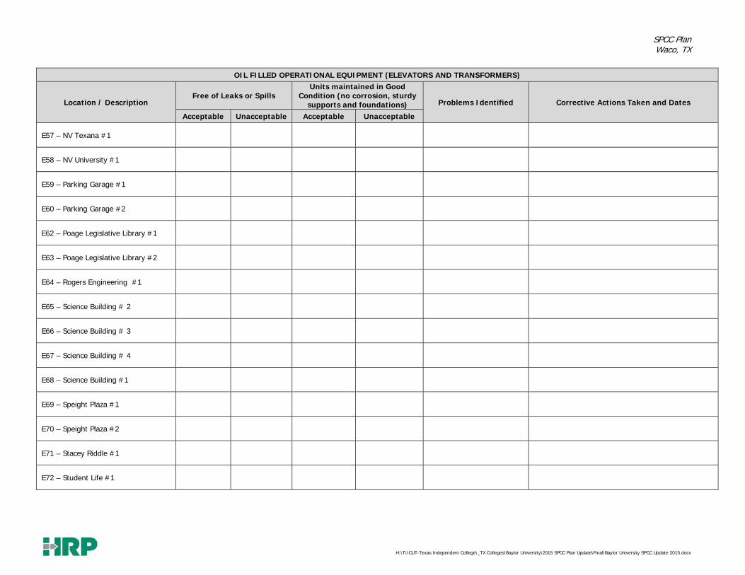
SPCC Plan Waco, TX
H:\T\ICUT-Texas Independent College\_TX Colleges\Baylor University\2015 SPCC Plan Update\Final\Baylor University SPCC Update 2015.docx
OIL FILLED OPERATIONAL EQUIPMENT (ELEVATORS AND TRANSFORMERS)
Location / Description Free of Leaks or Spills
Units maintained in Good Condition (no corrosion, sturdy
supports and foundations) Problems Identified Corrective Actions Taken and Dates
Acceptable Unacceptable Acceptable Unacceptable
E57 – NV Texana #1
E58 – NV University #1
E59 – Parking Garage #1
E60 – Parking Garage #2
E62 – Poage Legislative Library #1
E63 – Poage Legislative Library #2
E64 – Rogers Engineering #1
E65 – Science Building # 2
E66 – Science Building # 3
E67 – Science Building # 4
E68 – Science Building #1
E69 – Speight Plaza #1
E70 – Speight Plaza #2
E71 – Stacey Riddle #1
E72 – Student Life #1

SPCC Plan Waco, TX
H:\T\ICUT-Texas Independent College\_TX Colleges\Baylor University\2015 SPCC Plan Update\Final\Baylor University SPCC Update 2015.docx
OIL FILLED OPERATIONAL EQUIPMENT (ELEVATORS AND TRANSFORMERS)
Location / Description Free of Leaks or Spills
Units maintained in Good Condition (no corrosion, sturdy
supports and foundations) Problems Identified Corrective Actions Taken and Dates
Acceptable Unacceptable Acceptable Unacceptable
E73 – Truett Seminary #1
E74 – Umphrey Law 1st Floor
E75 – Umphrey Law 2nd Floor

SPCC Plan Waco, TX
H:\T\ICUT-Texas Independent College\_TX Colleges\Baylor University\2015 SPCC Plan Update\Final\Baylor University SPCC Update 2015.docx
SPCC PLAN INSPECTION LOG BAYLOR UNIVERSITY
WACO, TEXAS Inspection Date: Inspector Name/Title: Inspection Time: Weather Conditions:
OIL FILLED OPERATIONAL EQUIPMENT (ELEVATORS AND TRANSFORMERS)
Location / Description Free of Leaks or Spills
Units maintained in Good Condition (no corrosion, sturdy
supports and foundations) Problems Identified Corrective Actions Taken and Dates
Acceptable Unacceptable Acceptable Unacceptable
Transformers
T2 – Armstrong Browning Lib
T4 – Baylor Substation
T5 – Baylor Substation
T6 – BEC #30
T7 – BEC Transformer 40 A
T10 – BEC-Chiller #1
T11 – BEC-Chiller #6
T12 – BEC-Cogen
T13 – BECV-#1020
T79 – BEC-Chiller 2
T14 – Bill Dan Hist Village
T15 – Bill Daniels Student Center
T16 – Black Box Opera Building
T17 – Brooks College
T18 – Brooks Flats
T20 – Carroll Library Building
T21 – Carroll Science
T22 – Castellaw Building
T23 – Collins Hall
T24 – Collins Hall
T25 – Collins Hall
T26 – Crenshaw Student Foundation

SPCC Plan Waco, TX
H:\T\ICUT-Texas Independent College\_TX Colleges\Baylor University\2015 SPCC Plan Update\Final\Baylor University SPCC Update 2015.docx
OIL FILLED OPERATIONAL EQUIPMENT (ELEVATORS AND TRANSFORMERS)
Location / Description Free of Leaks or Spills
Units maintained in Good Condition (no corrosion, sturdy
supports and foundations) Problems Identified Corrective Actions Taken and Dates
Acceptable Unacceptable Acceptable Unacceptable
Transformers
T27 – Draper
T28 – East Parking
T29 – East Village – Earle
T30 – East Village – Teal
T31 – Ferrell Event Ctr
T32 – Ferrell Field House
T33 – Ferrell Sports Complex
T34 – Fine Arts Building
T35 – Hankamer Business
T36 – Hankamer Business
T37 – Highers Athletic Complex
T38 – Hurd Tennis Center
T39 – Jones, Moody, Poage Library T40 – Kokernot Hall
T3 – LL Sams – Temporarily Out of Service
T41 - LL Sams - Temporarily Out of Service
T42 - LL Sams - Temporarily Out of Service
T43 - LL Sams - Temporarily Out of Service 3
T44 - LL Sams - Temporarily Out of Service 4
T45 - LL Sams - Temporarily Out of Service 5
T46 - LL Sams - Temporarily Out of Service 6
T47 - Marina 75V2060
T48 - Marrs McLean Gym T49 - Marrs McLean Gym - Tennis Courts
T50 - Marrs McLean Science Building

SPCC Plan Waco, TX
H:\T\ICUT-Texas Independent College\_TX Colleges\Baylor University\2015 SPCC Plan Update\Final\Baylor University SPCC Update 2015.docx
OIL FILLED OPERATIONAL EQUIPMENT (ELEVATORS AND TRANSFORMERS)
Location / Description Free of Leaks or Spills
Units maintained in Good Condition (no corrosion, sturdy
supports and foundations) Problems Identified Corrective Actions Taken and Dates
Acceptable Unacceptable Acceptable Unacceptable
Transformers T51 - Mary Gibbs Jones Family & Consumer Sciences
T52 - Martin Hall
T53 - Martin Hall
T54 - Martin Home Mgmt, House
T55 - Mayborn Museum
T56 - McCrary Music Building
T57 - McCrary Music Building
T58 - Memorial Hall
T59 - Miller Chapel
T60 - Morrison Hall
T61 - Neil Morris Hall
T62 - North Village - Community Ctr
T63 - North Village - Heritage House
T64 - North Village - Texana House
T65 - North Village - University House
T66 - Rogers Engineering
T67 - Russell Gym
T68 - Russell Hall
T69 - Sid Richardson
T70 - Soccer Field
T71 - Speight Plaza Garage
T72 - Speight-Jenkins Apts
T73 - Speight-Jenkins Apts
T74 - Speight-Jenkins Apts
T75 - Stacey Riddle Center
T76 - Student Life Center
T77 - Truett Building
T78 - Umphrey Law Center

SPCC Plan Waco, TX
H:\T\ICUT-Texas Independent College\_TX Colleges\Baylor University\2015 SPCC Plan Update\Final\Baylor University SPCC Update 2015.docx
OIL FILLED OPERATIONAL EQUIPMENT (ELEVATORS AND TRANSFORMERS)
Location / Description Free of Leaks or Spills
Units maintained in Good Condition (no corrosion, sturdy
supports and foundations) Problems Identified Corrective Actions Taken and Dates
Acceptable Unacceptable Acceptable Unacceptable
Transformers
T80 – Penland Dining
T82 – Dutton
T83 – Dutton
T84 – Floyd Casey North End Zone
T85 – Hart Track & Field
T86 – Elliston Chapel
T87 – McLane Stadium Boardwalk
T88 – Tailgate Parking #1
T89 – Tailgate Parking #2
T90 – Tailgate Parking #3
T91 – Tailgate Parking #4
T92 – South 7th & Alexander Hall

SPCC Plan Waco, TX
H:\T\ICUT-Texas Independent College\_TX Colleges\Baylor University\2015 SPCC Plan Update\Final\Baylor University SPCC Update 2015.docx
SPCC PLAN INSPECTION LOG BAYLOR UNIVERSITY
WACO, TEXAS Inspection Date: Inspector Name/Title: Inspection Time: Weather Conditions:
BULK STORAGE CONTAINERS
Tank Location/ Description
Secondary Containment
Maintained (complete dike draining log as
necessary)
Fill and Drain Valves Securely Locked
Free of Leaks or Spills
Containers and piping in Good Condition (no
corrosion, sturdy supports and foundations)
Level Indicator Functional
Problems Identified (enter work order as
necessary)
Corrective Actions Taken
& Date
Acceptable Unacceptable Acceptable Unacceptable Acceptable Unacceptable Acceptable Unacceptable Acceptable Unacceptable
Emergency Generator Belly Tanks Armstrong Browning Library
Baylor Science Building
Clifton Robinson Tower
Draper
Dutton Parking
Ferrell Center
LL Sams
Speight Plaza
Student Life Center
BRIC
Foster Innovation
McLane Stadium
Hart Track & Field
Mars McLean Science
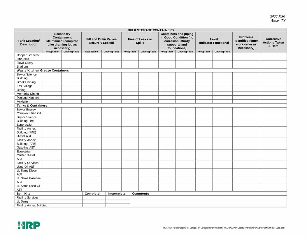
SPCC Plan Waco, TX
H:\T\ICUT-Texas Independent College\_TX Colleges\Baylor University\2015 SPCC Plan Update\Final\Baylor University SPCC Update 2015.docx
BULK STORAGE CONTAINERS
Tank Location/ Description
Secondary Containment
Maintained (complete dike draining log as
necessary)
Fill and Drain Valves Securely Locked
Free of Leaks or Spills
Containers and piping in Good Condition (no
corrosion, sturdy supports and foundations)
Level Indicator Functional
Problems Identified (enter work order as
necessary)
Corrective Actions Taken
& Date
Acceptable Unacceptable Acceptable Unacceptable Acceptable Unacceptable Acceptable Unacceptable Acceptable Unacceptable
Hooper Schaefer Fine Arts
Floyd Casey Stadium
Waste Kitchen Grease Containers Baylor Science Building
Brooks Dining East Village Dining
Memorial Dining Penland Kitchen McMullen Tanks & Containers Baylor Energy Complex Used Oil
Baylor Science Building Fire Suppression
Facility Annex Building (FAB) Diesel AST
Facility Annex Building (FAB) Gasoline AST
Equestrian Center Diesel AST
Facility Services Used Oil AST
LL Sams Diesel AST
LL Sams Gasoline AST
LL Sams Used Oil AST
Spill Kits Complete Incomplete Comments Facility Services
LL Sams Facility Annex Building
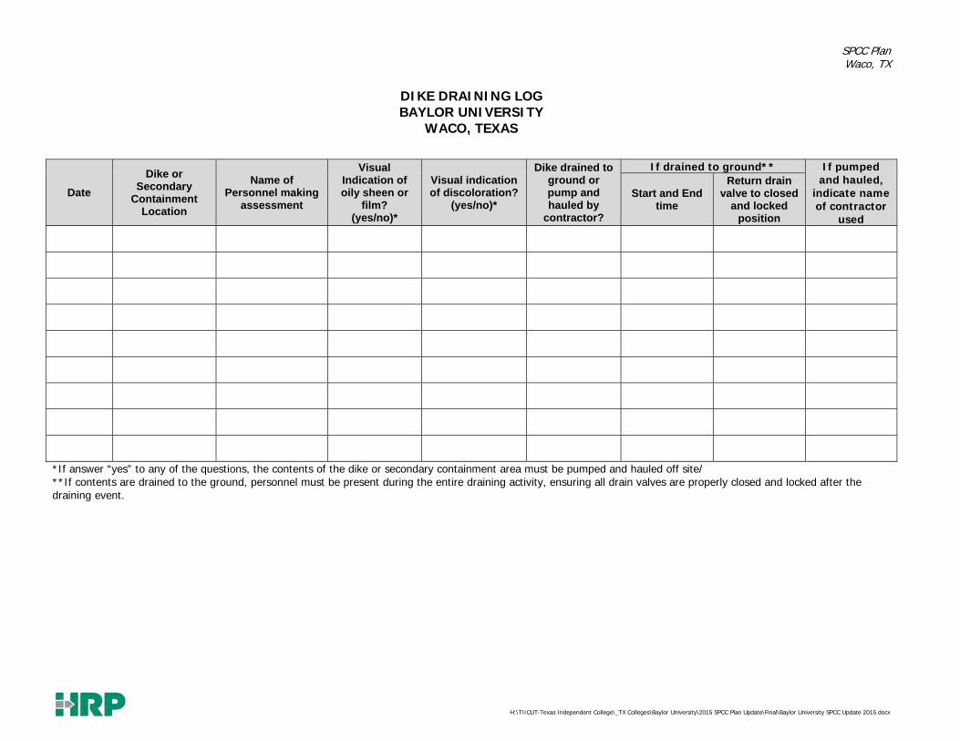
SPCC Plan Waco, TX
H:\T\ICUT-Texas Independent College\_TX Colleges\Baylor University\2015 SPCC Plan Update\Final\Baylor University SPCC Update 2015.docx
DIKE DRAINING LOG BAYLOR UNIVERSITY
WACO, TEXAS
Date
Dike or Secondary
Containment Location
Name of Personnel making
assessment
Visual Indication of oily sheen or
film? (yes/no)*
Visual indication of discoloration?
(yes/no)*
Dike drained to ground or pump and hauled by
contractor?
If drained to ground** If pumped and hauled,
indicate name of contractor
used
Start and End time
Return drain valve to closed
and locked position
*If answer “yes” to any of the questions, the contents of the dike or secondary containment area must be pumped and hauled off site/ **If contents are drained to the ground, personnel must be present during the entire draining activity, ensuring all drain valves are properly closed and locked after the draining event.

SPCC Plan Waco, TX
H:\T\ICUT-Texas Independent College\_TX Colleges\Baylor University\2015 SPCC Plan Update\Final\Baylor University SPCC Update 2015.docx
ANNUAL INTEGRITY INSPECTION LOG Baylor University
Inspection Date: _______________ Inspector Name/Title:____________________________ _ Inspection Time: ___________________ Signature:_______________________________________________
Container ID
Cont
ainm
ent
stru
ctur
e in
sa
tisfa
ctor
y co
nditi
on?
Dra
inag
e pi
pes/
valv
es w
ithin
co
ntai
nmen
t f
it fo
r co
ntin
ued
serv
ice
Evid
ence
of
tank
set
tlem
ent
or
foun
datio
n w
asho
ut
Crac
king
or
spal
ling
of
foun
datio
n Ta
nk s
uppo
rts
in s
atis
fact
ory
cond
ition
W
ater
abl
e to
dra
in a
way
fro
m
tank
G
roun
ding
str
ap s
ecur
ed a
nd
in g
ood
cond
ition
Ev
iden
ce o
f pa
int
failu
re
Any
dam
age
evid
ent
to t
he
tank
she
ll?
Flan
ged
conn
ectio
n bo
lts t
ight
an
d fu
lly e
ngag
ed w
ith n
o si
gn
of w
ear
or c
orro
sion
St
andi
ng w
ater
on
tank
Vent
s fr
ee o
f ob
stru
ctio
ns
Emer
genc
y ve
nt o
pera
ble?
Lift
as
re q
uire
d In
sula
tion
dam
aged
or
mis
sing
Ar
e th
ere
notic
eabl
e ar
eas
of
moi
stur
e on
the
insu
latio
n M
old
on in
sula
tion
Is t
he in
sula
tion
suff
icie
ntly
pr
otec
ted
from
wat
er in
trus
ion
Has
the
tan
k liq
uid
leve
l se
nsin
g de
vice
bee
n te
sted
to
ensu
re p
rope
r op
erat
ion
Doe
s th
e ta
nk li
quid
leve
l se
nsin
g de
vice
ope
rate
as
requ
ired
Are
over
fill p
reve
ntio
n de
vice
s in
pro
per
wor
king
con
ditio
n Ar
e ta
nk g
roun
ding
line
s in
go
od c
ondi
tion
Is e
lect
rical
wiri
ng f
or c
ontr
ol
boxe
s/lig
hts
in g
ood
cond
ition
Comments Baylor Science Building Diesel AST (AST2)
Facility Annex Building Diesel AST (AST3)
Facility Annex Building Gasoline AST (AST4)
Facility Annex Building Used Oil AST (AST5)
Equestrian Center Diesel AST (AST6)
Facility Services Used Oil AST (AST7)
LL Sams Diesel AST (AST8)
LL Sams Gasoline AST (AST9)

SPCC Plan Waco, TX
H:\T\ICUT-Texas Independent College\_TX Colleges\Baylor University\2015 SPCC Plan Update\Final\Baylor University SPCC Update 2015.docx
ANNUAL INTEGRITY INSPECTION LOG Baylor University
Inspection Date: _______________ Inspector Name/Title:____________________________ _ Inspection Time: ___________________ Signature:_______________________________________________
Container ID
Cont
ainm
ent
stru
ctur
e in
sa
tisfa
ctor
y co
nditi
on?
Dra
inag
e pi
pes/
valv
es w
ithin
co
ntai
nmen
t f
it fo
r co
ntin
ued
serv
ice
Evid
ence
of
tank
set
tlem
ent
or
foun
datio
n w
asho
ut
Crac
king
or
spal
ling
of
foun
datio
n Ta
nk s
uppo
rts
in s
atis
fact
ory
cond
ition
W
ater
abl
e to
dra
in a
way
fro
m
tank
G
roun
ding
str
ap s
ecur
ed a
nd
in g
ood
cond
ition
Ev
iden
ce o
f pa
int
failu
re
Any
dam
age
evid
ent
to t
he
tank
she
ll?
Flan
ged
conn
ectio
n bo
lts t
ight
an
d fu
lly e
ngag
ed w
ith n
o si
gn
of w
ear
or c
orro
sion
St
andi
ng w
ater
on
tank
Vent
s fr
ee o
f ob
stru
ctio
ns
Emer
genc
y ve
nt o
pera
ble?
Lift
as
re q
uire
d In
sula
tion
dam
aged
or
mis
sing
Ar
e th
ere
notic
eabl
e ar
eas
of
moi
stur
e on
the
insu
latio
n M
old
on in
sula
tion
Is t
he in
sula
tion
suff
icie
ntly
pr
otec
ted
from
wat
er in
trus
ion
Has
the
tan
k liq
uid
leve
l se
nsin
g de
vice
bee
n te
sted
to
ensu
re p
rope
r op
erat
ion
Doe
s th
e ta
nk li
quid
leve
l se
nsin
g de
vice
ope
rate
as
requ
ired
Are
over
fill p
reve
ntio
n de
vice
s in
pro
per
wor
king
con
ditio
n Ar
e ta
nk g
roun
ding
line
s in
go
od c
ondi
tion
Is e
lect
rical
wiri
ng f
or c
ontr
ol
boxe
s/lig
hts
in g
ood
cond
ition
Comments LL Sams Used Oil AST (AST10)
Baylor Science Building Kitchen Grease (KG1)
Bill Daniel Kitchen Grease (KG2)
Brooks Dining Kitchen Grease (KG3)
East Village Dining Kitchen Grease (KG4)
Memorial Dining Kitchen Grease (KG5)
Penland Kitchen Kitchen Grease (KG6)
McMullen Kitchen Grease (KG7)

SPCC Plan Waco, TX
H:\T\ICUT-Texas Independent College\_TX Colleges\Baylor University\2015 SPCC Plan Update\Final\Baylor University SPCC Update 2015.docx
ANNUAL INTEGRITY INSPECTION LOG Baylor University
Inspection Date: _______________ Inspector Name/Title:____________________________ _ Inspection Time: ___________________ Signature:_______________________________________________
Container ID
Cont
ainm
ent
stru
ctur
e in
sa
tisfa
ctor
y co
nditi
on?
Dra
inag
e pi
pes/
valv
es w
ithin
co
ntai
nmen
t f
it fo
r co
ntin
ued
serv
ice
Evid
ence
of
tank
set
tlem
ent
or
foun
datio
n w
asho
ut
Crac
king
or
spal
ling
of
foun
datio
n Ta
nk s
uppo
rts
in s
atis
fact
ory
cond
ition
W
ater
abl
e to
dra
in a
way
fro
m
tank
G
roun
ding
str
ap s
ecur
ed a
nd
in g
ood
cond
ition
Ev
iden
ce o
f pa
int
failu
re
Any
dam
age
evid
ent
to t
he
tank
she
ll?
Flan
ged
conn
ectio
n bo
lts t
ight
an
d fu
lly e
ngag
ed w
ith n
o si
gn
of w
ear
or c
orro
sion
St
andi
ng w
ater
on
tank
Vent
s fr
ee o
f ob
stru
ctio
ns
Emer
genc
y ve
nt o
pera
ble?
Lift
as
re q
uire
d In
sula
tion
dam
aged
or
mis
sing
Ar
e th
ere
notic
eabl
e ar
eas
of
moi
stur
e on
the
insu
latio
n M
old
on in
sula
tion
Is t
he in
sula
tion
suff
icie
ntly
pr
otec
ted
from
wat
er in
trus
ion
Has
the
tan
k liq
uid
leve
l se
nsin
g de
vice
bee
n te
sted
to
ensu
re p
rope
r op
erat
ion
Doe
s th
e ta
nk li
quid
leve
l se
nsin
g de
vice
ope
rate
as
requ
ired
Are
over
fill p
reve
ntio
n de
vice
s in
pro
per
wor
king
con
ditio
n Ar
e ta
nk g
roun
ding
line
s in
go
od c
ondi
tion
Is e
lect
rical
wiri
ng f
or c
ontr
ol
boxe
s/lig
hts
in g
ood
cond
ition
Comments Armstrong Browning Generator (EG1)
Clifton Robinson Tower Generator (EG2)
Draper Generator (EG3)
Dutton Parking Generator (EG4)
Ferrell Center Generator (EG5)
LL Sams Generator (EG6)
Baylor Science Building Generator (EG7)
Speight Plaza Generator (EG8)

SPCC Plan Waco, TX
H:\T\ICUT-Texas Independent College\_TX Colleges\Baylor University\2015 SPCC Plan Update\Final\Baylor University SPCC Update 2015.docx
ANNUAL INTEGRITY INSPECTION LOG Baylor University
Inspection Date: _______________ Inspector Name/Title:____________________________ _ Inspection Time: ___________________ Signature:_______________________________________________
Container ID
Cont
ainm
ent
stru
ctur
e in
sa
tisfa
ctor
y co
nditi
on?
Dra
inag
e pi
pes/
valv
es w
ithin
co
ntai
nmen
t f
it fo
r co
ntin
ued
serv
ice
Evid
ence
of
tank
set
tlem
ent
or
foun
datio
n w
asho
ut
Crac
king
or
spal
ling
of
foun
datio
n Ta
nk s
uppo
rts
in s
atis
fact
ory
cond
ition
W
ater
abl
e to
dra
in a
way
fro
m
tank
G
roun
ding
str
ap s
ecur
ed a
nd
in g
ood
cond
ition
Ev
iden
ce o
f pa
int
failu
re
Any
dam
age
evid
ent
to t
he
tank
she
ll?
Flan
ged
conn
ectio
n bo
lts t
ight
an
d fu
lly e
ngag
ed w
ith n
o si
gn
of w
ear
or c
orro
sion
St
andi
ng w
ater
on
tank
Vent
s fr
ee o
f ob
stru
ctio
ns
Emer
genc
y ve
nt o
pera
ble?
Lift
as
re q
uire
d In
sula
tion
dam
aged
or
mis
sing
Ar
e th
ere
notic
eabl
e ar
eas
of
moi
stur
e on
the
insu
latio
n M
old
on in
sula
tion
Is t
he in
sula
tion
suff
icie
ntly
pr
otec
ted
from
wat
er in
trus
ion
Has
the
tan
k liq
uid
leve
l se
nsin
g de
vice
bee
n te
sted
to
ensu
re p
rope
r op
erat
ion
Doe
s th
e ta
nk li
quid
leve
l se
nsin
g de
vice
ope
rate
as
requ
ired
Are
over
fill p
reve
ntio
n de
vice
s in
pro
per
wor
king
con
ditio
n Ar
e ta
nk g
roun
ding
line
s in
go
od c
ondi
tion
Is e
lect
rical
wiri
ng f
or c
ontr
ol
boxe
s/lig
hts
in g
ood
cond
ition
Comments Student Life Center Generator (EG9)
BRIC Generator (EG10)
Foster Innovation Generator (EG11)
McLane Stadium Generator (EG12)
Hart Track & Field Generator (EG13)
Mars MacLean Science Generator (EG14)
Hooper Schaefer Generator (EG15)
Floyd Casey Stadium Generator (EG16)

SPCC Plan Waco, TX
H:\T\ICUT-Texas Independent College\_TX Colleges\Baylor University\2015 SPCC Plan Update\Final\Baylor University SPCC Update 2015.docx
APPENDIX E CERTIFICATION OF THE
APPLICABILITY OF THE SUBSTANTIAL HARM CRITERIA
CHECKLIST

SPCC Plan Waco, TX
H:\T\ICUT-Texas Independent College\_TX Colleges\Baylor University\2015 SPCC Plan Update\Final\Baylor University SPCC Update 2015.docx
CERTIFICATION FOR FACILITIES THAT DO NOT POSE SUBSTANTIAL HARM Facility Name: Baylor University Facility Address: One Bear Place, Waco, Texas 1. Does the facility have a maximum storage capacity greater than or equal to
42,000 gallons and do the operations include over water transfers of oil to or from vessels?
Yes No X 2. Does the facility have a maximum storage capacity greater than or equal to one
million (1,000,000) gallons and is the facility without secondary containment for each above ground storage area sufficiently large to contain the capacity of the largest above ground storage tank within the storage area?
Yes No X 3. Does the facility have a maximum storage capacity greater than or equal to one
million (1,000,000) gallons and is the facility located at a distance (as calculated using the appropriate formula in Attachment C-III or an alternative formula1 considered acceptable by the RA) such that a discharge from the facility could cause injury to an environmentally sensitive area as defined in Appendix D?
Yes No X 4. Does the facility have a maximum storage capacity greater than or equal to one
million (1,000,000) gallons and is the facility located at a distance (as calculated using the appropriate formula in Attachment C-III or an alternative formula1 considered acceptable by the RA) such that a discharge from the facility would shut down a public drinking water intake?
Yes No X 5. Does the facility have a maximum storage capacity greater than or equal to one
million (1,000,000) gallons and within the past 5 years, has the facility experi-enced a reportable spill in any amount greater than or equal to 10,000 gallons?
Yes No X
1 If an alternative formula is used, documentation of the reliability and analytical soundness of
the alternative formula must be attached to this form.

SPCC Plan Waco, TX
H:\T\ICUT-Texas Independent College\_TX Colleges\Baylor University\2015 SPCC Plan Update\Final\Baylor University SPCC Update 2015.docx
CERTIFICATION FOR FACILITIES THAT DO NOT POSE SUBSTANTIAL HARM I certify under penalty of law that I have personally examined and am familiar with the information submitted in this document, and that based on my inquiry of those individuals responsible for obtaining this information, I believe that the submitted information is true, accurate, and complete.
Signature Dr. James Karban Name (Please type or print)
Director, Environmental Health & Safety _________________________________________________ Title (Please type or print)
_________________________________________________ Date
SPCC Plan Waco, TX
H:\T\ICUT-Texas Independent College\_TX Colleges\Baylor University\2015 SPCC Plan Update\Final\Baylor University SPCC Update 2015.docx
APPENDIX F TRAINING ROSTER
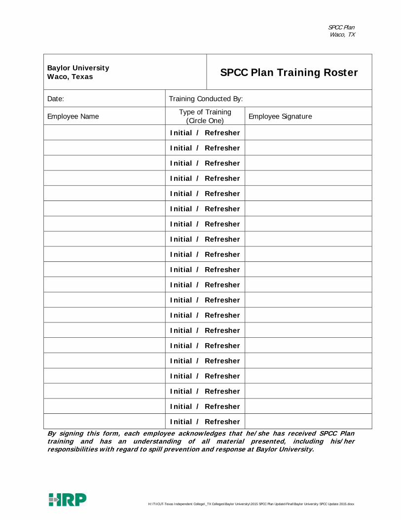
SPCC Plan Waco, TX
H:\T\ICUT-Texas Independent College\_TX Colleges\Baylor University\2015 SPCC Plan Update\Final\Baylor University SPCC Update 2015.docx
Baylor University Waco, Texas SPCC Plan Training Roster
Date: Training Conducted By:
Employee Name Type of Training (Circle One) Employee Signature
Initial / Refresher
Initial / Refresher
Initial / Refresher
Initial / Refresher
Initial / Refresher
Initial / Refresher
Initial / Refresher
Initial / Refresher
Initial / Refresher
Initial / Refresher
Initial / Refresher
Initial / Refresher
Initial / Refresher
Initial / Refresher
Initial / Refresher
Initial / Refresher
Initial / Refresher
Initial / Refresher
Initial / Refresher
Initial / Refresher
By signing this form, each employee acknowledges that he/she has received SPCC Plan training and has an understanding of all material presented, including his/her responsibilities with regard to spill prevention and response at Baylor University.

SPCC Plan Waco, TX
H:\T\ICUT-Texas Independent College\_TX Colleges\Baylor University\2015 SPCC Plan Update\Final\Baylor University SPCC Update 2015.docx
APPENDIX G PHOTO LOG OF OIL STORAGE
LOCATIONS

SPCC Plan Waco, TX
H:\T\ICUT-Texas Independent College\_TX Colleges\Baylor University\2015 SPCC Plan Update\Final\Baylor University SPCC Update 2015.docx
Baylor Energy Complex Used Oil Drums (AST1)
Baylor Science Building Fire Suppression System Diesel AST
(AST2)
Facility Annex Building (FAB) Diesel AST (AST 3)
Facility Annex Building (FAB) Gasoline AST (AST4)
Facility Annex Building (FAB) Used Oil Collection Point (AST5)
Equestrian Center Diesel AST (AST6)

SPCC Plan Waco, TX
H:\T\ICUT-Texas Independent College\_TX Colleges\Baylor University\2015 SPCC Plan Update\Final\Baylor University SPCC Update 2015.docx
Facility Services Used Oil AST (AST7)
LL Sams Diesel AST (AST8)
LL Sams Gasoline AST (AST9)
LL Sams Used Oil AST (AST10)
Armstrong Browning Generator (EG1)

SPCC Plan Waco, TX
H:\T\ICUT-Texas Independent College\_TX Colleges\Baylor University\2015 SPCC Plan Update\Final\Baylor University SPCC Update 2015.docx
Clifton Robinson Tower EG Day Tank (EG2)
Draper Generator (EG3)
Dutton Parking Generator (EG4)
Ferrell Center Generator (EG5)
LL Sams Generator (EG6)
Science Building Generator (EG7)
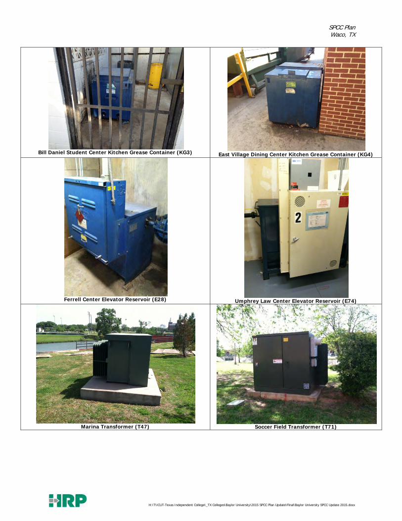
SPCC Plan Waco, TX
H:\T\ICUT-Texas Independent College\_TX Colleges\Baylor University\2015 SPCC Plan Update\Final\Baylor University SPCC Update 2015.docx
Bill Daniel Student Center Kitchen Grease Container (KG3)
East Village Dining Center Kitchen Grease Container (KG4)
Ferrell Center Elevator Reservoir (E28)
Umphrey Law Center Elevator Reservoir (E74)
Marina Transformer (T47)
Soccer Field Transformer (T71)

SPCC Plan Waco, TX
H:\T\ICUT-Texas Independent College\_TX Colleges\Baylor University\2015 SPCC Plan Update\Final\Baylor University SPCC Update 2015.docx
LL Sams Transformers (In Storage) (T3, T41-T46)
McMullen Kitchen Grease (KG7)
Foster Innovation Generator Day Tank (EG11)
Elliston Chapel Transformer (T86)
Hooper Schaefer Emergency Generator (EG15)

SPCC Plan Waco, TX
H:\T\ICUT-Texas Independent College\_TX Colleges\Baylor University\2015 SPCC Plan Update\Final\Baylor University SPCC Update 2015.docx
McLane Stadium Emergency Generator (EG12)
McLane Stadium – Tailgate Parking 1 (T90)
McLane Stadium – Tailgate Parking 2 (T91)
McLane Stadium – Tailgate Parking 3 (T92)

SPCC Plan Waco, TX
H:\T\ICUT-Texas Independent College\_TX Colleges\Baylor University\2015 SPCC Plan Update\Final\Baylor University SPCC Update 2015.docx
McLane Stadium – Tailgate Parking 4 (T93)
Hart Track & Field Emergency Generator (EG13)
BRIC Emergency Generator (EG10)
Mars MacLean Science Emergency Generator (EG14)