Embed Size (px)
Citation preview
Reach, Reliability and ROI: Building The Optimal Subsea ArchitectureIntroductionIn 1872, Hans Christian Andersen was one of the first people to recognize that subsea networks were going to be big. He wrote a children’s book to help educate the world about “the serpent beneath the sea.” Since then, subsea networks have come a long way. Subsea operators, recognizing the mission critical nature of international communications, pride themselves on the ultra-reliability of their network and the ability of fiber optic cables to span the entire globe and bring all of us a little closer together. This paper will take a deeper look at subsea architecture, its evolution, recent technological advances and industry best practices that promise to dramatically improve return on investment.
WHITE PAPER
Page 2
While terrestrial optical networks are designed to rigorous standards, subsea networks are designed to even more stringent standards and have historically tended to be more expensive. In some cases, the focus on reach and reliability required custom components and special testing to prove the design could survive the toughest environments reaching the furthest distances. The trade-off resulted in a noticeable delay in obtaining the latest technology. Many subsea networks still operate with 2.5 Gb/s and 10 Gb/s wavelengths versus their terrestrial counterparts, which are in the midst of a rapid shift to 100 Gb/s wavelengths. Migrations to volume manufactured solutions were often treated as a trade-off against other critical requirements, such as reach and reliability.
However, recent technological innovations including photonic integration, soft-decision forward error correction (SD-FEC) and programmable modulation are enabling subsea upgrades with both performance and reliability, leveraging the sunk (no pun intended) investment and delivering a ”dramatic” improvement in the overall network. These technologies, along with ultra-long reach, 500G and future terabit super-channels, ultra-reliable photonic integrated circuits (PICs) and intelligent generalized multi-protocol label switching (GMPLS) control plane enable scale and reliability. Further seamless operations with terrestrial networks without the use of back-to-back transponders further reduces cost and speeds up return on investment.
The Need for a New Paradigm
Critical elements of any subsea architecture include capacity, reach, distance, reliability, resilience and return on investment. The first three elements are straightforward; however, the fourth element assumes more than technology, it assumes a new subsea paradigm that takes advantage of new technology in such a way that rapid return on investment can be made while sustaining lower operational costs, higher levels of integration between subsea and terrestrial networks and low cost per Gb/s of capacity.
An example of that new subsea paradigm could include elements of the following:
Architecture That Has Changed to Adapt with the Times
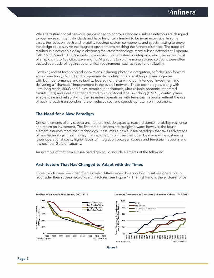
Three trends have been identified as behind-the-scenes drivers in forcing subsea operators to reconsider their subsea networks architectures (see Figure 1). The first trend is the end-user price
10 Gbps Wavelength Price Trends, 2003-2011 Countries Connected to 3 or More Submarine Cables, 1989-2012
Figure 1
decline of international bandwidth. With the steep price erosion of international circuits ranging from 10 to 15% per year, subsea network operators have become extremely sensitive to how much their network will cost to own and operate, and this has forced a trend away from custom designed and manufactured equipment to volume manufactured equipment, as long as it does not impact service reliability.
The second key trend is increased competition across subsea systems. This is a direct result of more countries demanding to connect to more international fiber systems, preferably on shorter, higher performance routes and for the best possible prices.
The results identify the third key trend, which is in customer demand for subsea upgrades that must be delivered in shorter intervals, with lower prices and demand for faster innovation. Many of those innovations will come in the form of advancements that will drive greater reach and capacity per fiber system and will result in a better overall business case. Some of those technological innovations are discussed below.
Balancing System Reach and Capacity
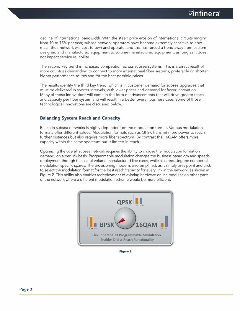
Reach in subsea networks is highly dependent on the modulation format. Various modulation formats offer different values. Modulation formats such as QPSK transmit more power to reach further distances but also require more fiber spectrum. By contrast the 16QAM offers more capacity within the same spectrum but is limited in reach.
Optimizing the overall subsea network requires the ability to choose the modulation format on demand, on a per link basis. Programmable modulation changes the business paradigm and speeds deployment through the use of volume manufactured line cards, while also reducing the number of modulation specific spares. The provisioning model is also simplified, as it simply uses point and click to select the modulation format for the best reach/capacity for every link in the network, as shown in Figure 2. This ability also enables redeployment of existing hardware or line modules on other parts of the network where a different modulation scheme would be more efficient.
Page 3
BPSK
QPSK
16QAMFlexCoherentTM Programmable Modulation
Enables Dial-a-Reach Functionality
Figure 2
Super-Channel Technology
Super-channel technology is an evolution of DWDM technology in which several optical carriers are combined to create a composite line side signal of the desired capacity, and which is provisioned in one operational cycle. Beyond operations, super-channels also improve spectrum utilization by allowing tighter channel spacing and guard band elimination, resulting in more overall capacity from the fiber asset. Super-channel technology is tightly coupled with coherent modulation, allowing the construction of super-channels that can be engineered for any reach dependent upon the proper modulation format chosen.
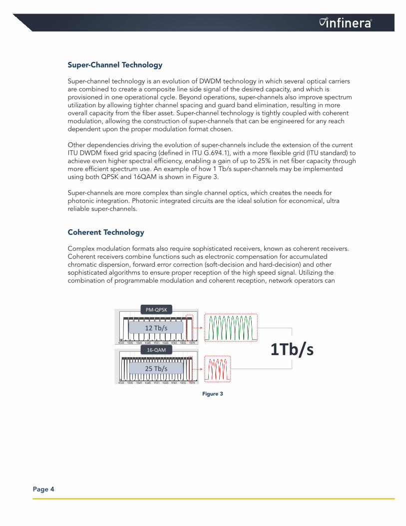
Other dependencies driving the evolution of super-channels include the extension of the current ITU DWDM fixed grid spacing (defined in ITU G.694.1), with a more flexible grid (ITU standard) to achieve even higher spectral efficiency, enabling a gain of up to 25% in net fiber capacity through more efficient spectrum use. An example of how 1 Tb/s super-channels may be implemented using both QPSK and 16QAM is shown in Figure 3.
Super-channels are more complex than single channel optics, which creates the needs for photonic integration. Photonic integrated circuits are the ideal solution for economical, ultra reliable super-channels.
Coherent Technology
Complex modulation formats also require sophisticated receivers, known as coherent receivers. Coherent receivers combine functions such as electronic compensation for accumulated chromatic dispersion, forward error correction (soft-decision and hard-decision) and other sophisticated algorithms to ensure proper reception of the high speed signal. Utilizing the combination of programmable modulation and coherent reception, network operators can
Page 4
7 | Infinera Confiden-al & Proprietary
FlexChannels Increase Total Fiber Capacity More complex modula6on → more capacity per fiber
PM-‐QPSK
16-‐QAM 1Tb/s 12 Tb/s
25 Tb/s
Figure 3
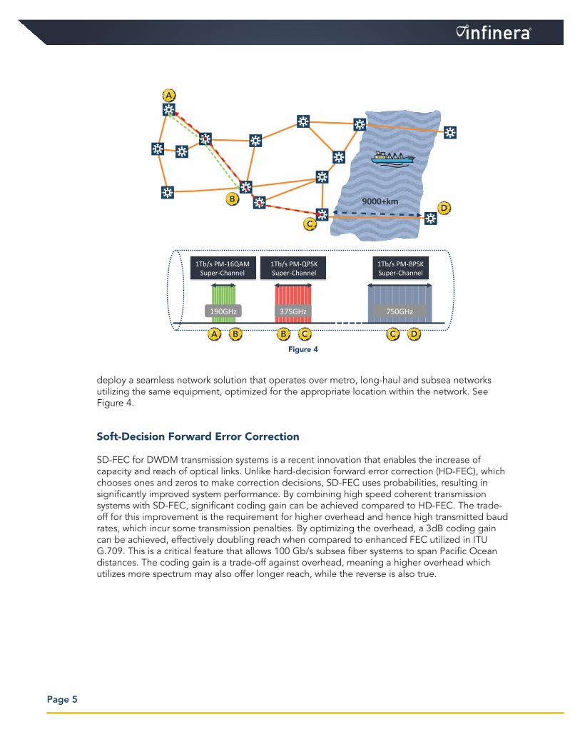
deploy a seamless network solution that operates over metro, long-haul and subsea networks utilizing the same equipment, optimized for the appropriate location within the network. See Figure 4.
Soft-Decision Forward Error Correction
SD-FEC for DWDM transmission systems is a recent innovation that enables the increase of capacity and reach of optical links. Unlike hard-decision forward error correction (HD-FEC), which chooses ones and zeros to make correction decisions, SD-FEC uses probabilities, resulting in significantly improved system performance. By combining high speed coherent transmission systems with SD-FEC, significant coding gain can be achieved compared to HD-FEC. The trade-off for this improvement is the requirement for higher overhead and hence high transmitted baud rates, which incur some transmission penalties. By optimizing the overhead, a 3dB coding gain can be achieved, effectively doubling reach when compared to enhanced FEC utilized in ITU G.709. This is a critical feature that allows 100 Gb/s subsea fiber systems to span Pacific Ocean distances. The coding gain is a trade-off against overhead, meaning a higher overhead which utilizes more spectrum may also offer longer reach, while the reverse is also true.
Page 5
1Tb/s PM-QPSKSuper-Channel
1Tb/s PM-16QAMSuper-Channel
1Tb/s PM-BPSKSuper-Channel
A
B
C
D9000+km
A B B C C D
375GHz190GHz 750GHz
Figure 4
When combined with FlexCoherentTM programmable modulation formats, SD-FEC enables the efficient trade-off between capacity and reach. Existing fiber systems can benefit from an SD-FEC upgrade by increasing overall spectral efficiency. For example, an existing HD-FEC 100 Gb/s BPSK signal may now be able to operate using QPSK with SD-FEC, effectively doubling system capacity in a given spectrum, while still maintaining or even extending original reach targets.
Opportunities to Maximize Return on Investment (ROI)
Subsea networks have long been considered special, for a number of reasons. Among others, they may include the need to:
1) Operate in demanding circumstances, under the sea, repairable only by special ships;2) Be the primary lifeline for many remote countries;3) Operate in any environment including salt water, teething sharks and boat anchors;4) Reach super-long distances (10,000 kilometers plus).
It is these requirements that force subsea fiber systems to be built to exacting specifications, tested and then re-tested to ensure that they work. In some cases the limitations have impacted performance, raised costs and extended delivery times of subsea network equipment. Until recently, the limited number of suppliers has been restricted to a few players. Today, the subsea market is split into “new” providers and ”upgrade” providers. New providers are full turnkey cable deployment providers, while upgrade providers focus on maximizing value from the existing wet plant. We will examine the upgrade opportunities.
While there are several areas for ROI improvement as part of a subsea upgrade, we will limit our examination to the following three opportunities.
Opportunity #1—Subsea and Terrestrial Integration
Integrating subsea and terrestrial networks can increase ROI. No longer are subsea networks required to sit on an island alone, with separate control and management. Instead, leveraging the coexistence of subsea and terrestrial transponders on the same common platforms in cable landing points, services can be provisioned from a terrestrial customer location anywhere on the network to a terrestrial location anywhere else, yet traversing a subsea network in between. The submarine line terminal equipment (SLTE) sites replace back-to-back transponders with full photonic integration, reducing both power and footprint required without compromising on transmission performances typical in all-optical implementation, while also increasing reliability
Page 6
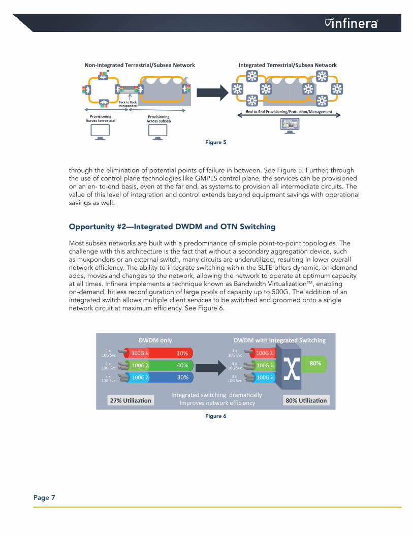
through the elimination of potential points of failure in between. See Figure 5. Further, through the use of control plane technologies like GMPLS control plane, the services can be provisioned on an en- to-end basis, even at the far end, as systems to provision all intermediate circuits. The value of this level of integration and control extends beyond equipment savings with operational savings as well.
Opportunity #2—Integrated DWDM and OTN Switching
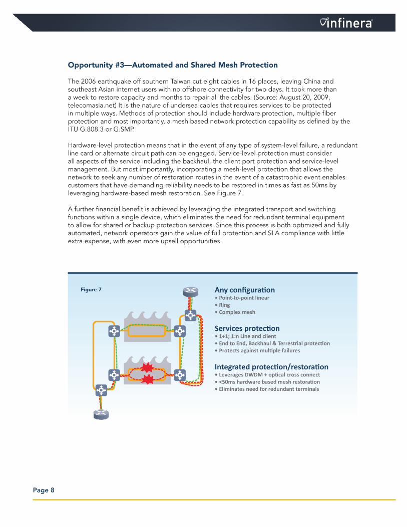
Most subsea networks are built with a predominance of simple point-to-point topologies. The challenge with this architecture is the fact that without a secondary aggregation device, such as muxponders or an external switch, many circuits are underutilized, resulting in lower overall network efficiency. The ability to integrate switching within the SLTE offers dynamic, on-demand adds, moves and changes to the network, allowing the network to operate at optimum capacity at all times. Infinera implements a technique known as Bandwidth VirtualizationTM, enabling on-demand, hitless reconfiguration of large pools of capacity up to 500G. The addition of an integrated switch allows multiple client services to be switched and groomed onto a single network circuit at maximum efficiency. See Figure 6.
Page 7
!"#$%&'(!)**)+,*$&'-./0+)&(1),23*4"Non-Integrated Terrestrial/Subsea Network"
Back to Back transponders
ProvisioningAcross terrestrial
ProvisioningAcross subsea
!"#$%&'(!)**)+,*$&'-./0+)&(1),23*4"Integrated Terrestrial/Subsea Network
End to End Provisioning/Protection/Management
Figure 5
!MN"
OMN"
CMN"
80%10%
40%
30%
1 x 10G Svc 100G
4 x 10G Svc 100G
100G
100G
100G
100G 3 x 10G Svc
1 x 10G Svc
4 x 10G Svc
3 x 10G Svc
Integrated switching dramatically Improves network efficiency
DWDM only DWDM with Integrated Switching
27% Utilization 80% Utilization
Figure 6
Page 8
Opportunity #3—Automated and Shared Mesh Protection
The 2006 earthquake off southern Taiwan cut eight cables in 16 places, leaving China and southeast Asian internet users with no offshore connectivity for two days. It took more than a week to restore capacity and months to repair all the cables. (Source: August 20, 2009, telecomasia.net) It is the nature of undersea cables that requires services to be protected in multiple ways. Methods of protection should include hardware protection, multiple fiber protection and most importantly, a mesh based network protection capability as defined by the ITU G.808.3 or G.SMP.
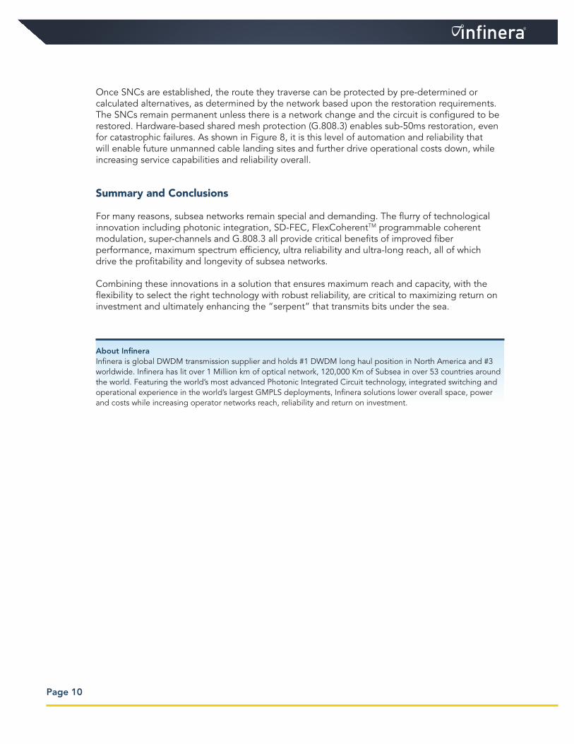
Hardware-level protection means that in the event of any type of system-level failure, a redundant line card or alternate circuit path can be engaged. Service-level protection must consider all aspects of the service including the backhaul, the client port protection and service-level management. But most importantly, incorporating a mesh-level protection that allows the network to seek any number of restoration routes in the event of a catastrophic event enables customers that have demanding reliability needs to be restored in times as fast as 50ms by leveraging hardware-based mesh restoration. See Figure 7.
A further financial benefit is achieved by leveraging the integrated transport and switching functions within a single device, which eliminates the need for redundant terminal equipment to allow for shared or backup protection services. Since this process is both optimized and fully automated, network operators gain the value of full protection and SLA compliance with little extra expense, with even more upsell opportunities.
Any configuration• Point-to-point linear• Ring• Complex mesh
Services protection• 1+1; 1:n Line and client• End to End, Backhaul & Terrestrial protection• Protects against multiple failures
Integrated protection/restoration• Leverages DWDM + optical cross connect• <50ms hardware based mesh restoration • Eliminates need for redundant terminals
Figure 7
Page 9
Maximizing the Return on Investment (ROI)
Leveraging many of the key technologies above will not only help drive greater network efficiency, longer reach and higher reliability, but also provide opportunities to increase ROI. However, maximizing ROI requires the right combination of the above technologies along with the network flexibility to adapt to your changing network and customer needs.
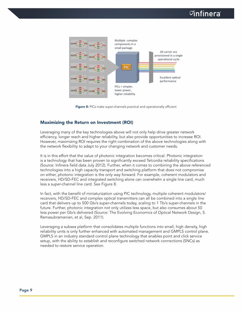
It is in this effort that the value of photonic integration becomes critical. Photonic integration is a technology that has been proven to significantly exceed Telcordia reliability specifications (Source: Infinera field data July 2012). Further, when it comes to combining the above referenced technologies into a high capacity transport and switching platform that does not compromise on either, photonic integration is the only way forward. For example, coherent modulators and receivers, HD/SD-FEC and integrated switching alone can overwhelm a single line card, much less a super-channel line card. See Figure 8.
In fact, with the benefit of miniaturization using PIC technology, multiple coherent modulators/receivers, HD/SD-FEC and complex optical transmitters can all be combined into a single line card that delivers up to 500 Gb/s super-channels today, scaling to 1 Tb/s super-channels in the future. Further, photonic integration not only utilizes less space, but also consumes about 50 less power per Gb/s delivered (Source: The Evolving Economics of Optical Network Design, S. Ramasubramanian, et al, Sep. 2011).
Leveraging a subsea platform that consolidates multiple functions into small, high density, high reliability units is only further enhanced with automated management and GMPLS control plane. GMPLS in an industry standard control plane technology that enables point and click service setup, with the ability to establish and reconfigure switched network connections (SNCs) as needed to restore service operation.
9 | Infinera Confiden-al & Proprietary
PICs make super-‐channels prac?cal & opera?onally efficient
PIC
PICs = simpler, lower power, higher reliability
Excellent op-cal performance
All carrier are provisioned in a single opera-onal cycle
Mul-ple complex components in a small package
Figure 8: PICs make super-channels practical and operationally efficient
Page 10
Once SNCs are established, the route they traverse can be protected by pre-determined or calculated alternatives, as determined by the network based upon the restoration requirements. The SNCs remain permanent unless there is a network change and the circuit is configured to be restored. Hardware-based shared mesh protection (G.808.3) enables sub-50ms restoration, even for catastrophic failures. As shown in Figure 8, it is this level of automation and reliability that will enable future unmanned cable landing sites and further drive operational costs down, while increasing service capabilities and reliability overall.
Summary and Conclusions
For many reasons, subsea networks remain special and demanding. The flurry of technological innovation including photonic integration, SD-FEC, FlexCoherentTM programmable coherent modulation, super-channels and G.808.3 all provide critical benefits of improved fiber performance, maximum spectrum efficiency, ultra reliability and ultra-long reach, all of which drive the profitability and longevity of subsea networks.
Combining these innovations in a solution that ensures maximum reach and capacity, with the flexibility to select the right technology with robust reliability, are critical to maximizing return on investment and ultimately enhancing the “serpent” that transmits bits under the sea.
About Infinera Infinera is global DWDM transmission supplier and holds #1 DWDM long haul position in North America and #3 worldwide. Infinera has lit over 1 Million km of optical network, 120,000 Km of Subsea in over 53 countries around the world. Featuring the world’s most advanced Photonic Integrated Circuit technology, integrated switching and operational experience in the world’s largest GMPLS deployments, Infinera solutions lower overall space, power and costs while increasing operator networks reach, reliability and return on investment.

Infinera Corporation140 Caspian CourtSunnyvale, CA 94089 USATelephone: +1 408 572 5200Fax: +1 408 572 5454www.infinera.com
Have a question about Infinera’s products or services?Please contact us via the email addresses below.
Americas: [email protected] & Pacific Rim: [email protected], Middle East, and Africa: [email protected] E-Mail: [email protected]
www.infinera.com
Specifications subject to change without notice.
Document Number: WP-SS-.9-2012© Copyright 2012 Infinera Corporation. All rights reserved.Infinera, Infinera DTN™, IQ™, Bandwidth Virtualization™, Digital Virtual Concatenation™ andInfinera Digital Optical Network™ are trademarks of Infinera Corporation