Embed Size (px)
Citation preview
Reaction Mechanisms for Graphene and Carbon Nanotube Fluorination
Sılvia Osuna,†,‡ Miquel Torrent-Sucarrat,† Miquel Sola,‡ Paul Geerlings,†
Christopher P. Ewels,*,§ and Gregory Van Lier*,†
Research Group of General Chemistry (ALGC), Vrije UniVersiteit Brussel s Free UniVersity of Brussels(VUB), Pleinlaan 2, B-1050 Brussels, Belgium, Institut de Quımica Computacional and Departament deQuımica, UniVersitat de Girona, E-17071 Girona, Catalonia, Spain, and Institut des Materiaux Jean Rouxel,CNRS, UniVersite de Nantes, 2 rue de la Houssiniere, 44322 Nantes, France
ReceiVed: September 14, 2009; ReVised Manuscript ReceiVed: December 19, 2009
Via density functional theory calculations, we explore the process of graphene and carbon nanotube fluorination.Contrary to graphene, HF-catalyzed carbon nanotube fluorination adds fluorine pairs at (1,4) spacing, naturallyleading to a self-organized C4F coverage, which can subsequently rearrange into dense axial C2F lines byfluorine diffusion upon solubilization or heat treatment. Controlling the fluorination process and subsequentnanotube processing results in fluorinated material types with unexplored electronic and chemical properties.
Introduction
There exist few techniques to date that allow variation ofthe properties of single carbon nanotubes along their length ina controlled manner or selective modification of regions of agraphene surface. Of the different chemical modificationtechniques available, fluorination takes a special place as it canprovide for full outerwall functionalization up to C2F fornanotubes and CF for graphene.1 A range of functionalizationmethods is available for carbon nanotubes using either atomicfluorine,2 F2 gas,3 inorganic fluorides such as BrF3
4,5 or XeF2,6
and radio frequency (RF) plasma functionalization.7 In particular,the latter fluorination method is easy, fast, and upscalable toindustrial levels with good control over the fluorination degree.
Fluorination is used to debundle and disperse carbon nano-tubes, enabling their solubilization in, for example, alcohols,8
expected to be due to hydrogen bonding between the surfacefluorine and the alcohol molecules.8,9 Potential applications forfluorinated nanotubes include the use in lithium ion batteries,10–13
supercapacitors,14 and as lubricants.15–17 Recently, they havebeen applied as a new route for polymer reinforcement, wherethey provide important improvement of the mechanical proper-ties of polymers as compared to pristine nanotube fillers.18,19
Subsequent defluorination is possible through sonication withanhydrous hydrazine. Also, upon heat treatment, defluorinationcan be achieved,2,8 which provides for a method of producingsolid conducting carbon nanotube blocks with good biocompati-bility.20,21 Fluorinated parts of nanotubes can also be etched awayupon heat treatment, resulting in short “cut” nanotubes.22
There has been much debate on the transport properties offunctionalized carbon nanotubes.23 Although a decrease of theconductivity has been measured for fluorinated nanotubes,24 theband gap has been predicted to vanish for metallic nanotubeswith an axial fluorine addition pattern.25,26 The study of thepossible addition patterns remains therefore an important issue.Self-organized surface fluorination should allow tuning of carbon
nanomaterial properties such as band gap and conductionchannels for transport behavior; however, in practice, studiesare lacking on precise control of the functionalization procedureand addition pattern characterization.
Fluorination of graphite has long been performed experimen-tally (for an overview, see ref 27) and allows further function-alization and solubilization,28 with possible application for fieldeffect transistors29 and battery applications.27,30 In fluorinatedgraphite, electrical conduction can be enhanced by promotingionic bonding between fluorine and carbon atoms, whichincreases the number of hole carriers, whereas covalent bondingproduces a decrease in the overall carrier concentration.31
For gas-phase fluorination of carbon nanotubes, two primaryphases have been described in the literature, which are obtainedupon increasing fluorination temperature; these are a low-densityphase up to a 20-25% F/C ratio and a higher density phase upto to 50% F/C ratio,32 with the transition temperature dependingon the specific treatment characteristics and carbon nanotubetype.2,33 While both average surface coverage below 25% andup to 50% has been observed by X-ray photoelectron spectros-copy for plasma and gas-phase fluorinated tubes depending ontreatment parameters, experimental observation by scanningtunneling microscopy (STM) for low surface coverage has onlyobserved fluorinated bands corresponding to C2F coverageseparated by pristine nanotube parts,34 attributed to the moststable equatorial addition pattern forming C2F bands with sharpequatorial edges.35 Nonetheless, these specific phases have beenpredicted as consisting of isolated benzenoid rings separatedby individual fluorinated carbons for the low-density phase,resulting in a maximal C4F ratio with local aromaticity playinga relevant role in the addition pattern,36 and consisting ofalternating lines of fluorinated and nonfluorinated carbons overthe whole nanotube surface for the high-density C2F phase.37
Notably, experimental evidence of the structure, formationprocess, and properties of C4F material is lacking. While graphitefluorination is a fundamentally different process since it involvespossible fluorine access to both sides of the carbon layer, wemight expect graphene to fluorinate with a similar additionmechanism to carbon nanotubes. However, despite the potentialinterest of such a material, proper characterization of the additionpatterns and mechanisms for fluorinated graphene are also
* To whom correspondence should be addressed. E-mail:[email protected]. Phone: +32-(0)26293516 (G.V.L.); [email protected]. Phone: +33-240376407 (C.P.E.).
† Vrije Universiteit Brussel - Free University of Brussels.‡ Universitat de Girona.§ Universite de Nantes.
J. Phys. Chem. C 2010, 114, 3340–33453340
10.1021/jp908887n 2010 American Chemical SocietyPublished on Web 02/10/2010
lacking to date. We therefore present here density functionaltheory (DFT) calculations to identify the precise fluorinationroute and full free-energy reaction barriers in HF-catalyzed gas-phase fluorination of graphene and carbon nanotubes. Weconfirm that this results in the C4F structure reported above atlower temperatures and explore the formation routes andproperties of hybrid C4F-C2F nanotubes. The fluorination ofgraphene is predicted to behave very differently with mixedsurface C2F/C4F functionalization.
Computational Details
All DFT calculations were performed using the Gaussian03program.38 The fluorine addition mechanism for graphene wasstudied using coronene as a test system and evaluated at the abinitio B3LYP39–41 level of theory with the standard 6-31G(d)42,43
basis set. In this case, all stationary points were characterizedas either minima or transition states by computing the vibrationalharmonic frequencies.44 Moreover, the study of full Gibbs freeenergies for the whole process was performed since all transi-tion-state (TS) structures involve three molecules, and thus, thefluorination reaction is expected to be entropically driven. Thenanotube fluorine addition was studied using an armchair (7,7)nanotube (C264H24) as a test system. The reaction mechanismwas studied within the two-layered ONIOM approach due tothe system size, which was recently shown to provide forcomparable results for reaction and activation energies as fullB3LYP calculations.45,46 The low level of the system was treatedwith the DFT XR exchange (R ) 2/3) functional in conjunctionwiththeelectron-gascorrelationfunctional(inVosko-Wilk-Nusairparametrization)47,48 using a 3-21G basis set,42,43 while a corehigh-level region of 24 carbon atoms (coronene patch) wastreated using the hybrid B3LYP method with 6-31G(d). Gibbsfree-energy calculations were performed on a coronene testsystem curved to mirror the curvature of a (7,7) nanotube dueto the high computational cost.
Migration barriers were studied using the synchronous transit-guided quasi-Newton (STQN) method as implemented bySchlegel and co-workers,49 and the QST2 and QST3 approacheswere used at the DFT B3LYP/3-21G level of theory again foran armchair (7,7) nanotube (C264H24). Solvent effects wereincluded using the polarizable continuum model (PCM),50 whereextra spheres were added inside of the nanotube to keep theinner core solvent-free. All minimum structures were reopti-mized with ethanol as the solvent; however, only single-pointenergy calculations were performed for all transition structuresdue to the computational cost for this system size.
Results and Discussion
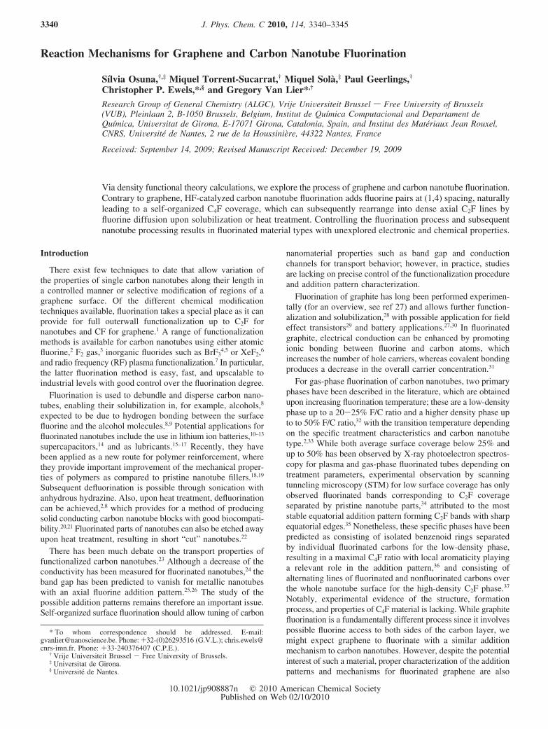
1. Fluorination Process for Graphene and for CarbonNanotubes. First, we analyze the gas-phase fluorination processfor graphene. Hereby, coronene is taken as a test system to allowthe study of full Gibbs free energies, which are important sinceall TS structures involve three molecules, and the fluorinationreaction is thus expected to be entropically driven. Figure 1presents the fluorine addition mechanism, showing all reactionintermediates, TSs, and reaction products found. The F2
molecule alone preferentially sits orthogonal to the coronenesurface (int1). When HF is also present, a hydrogen bond (int2,1.66 Å) is formed between HF and the “upper” fluorine atomof the F2 molecule, leading to the dissociation of F2 and theformation of the TS1 transition state, with an exothermicreaction energy of -5.8 kcal/mol (see Figure 1). However, theGibbs free energy for this dissociation describes a clearlyendothermic process (+13.1 kcal/mol), showing that this
reaction is indeed driven by the entropy. After the formation ofthe first fluorine bond with graphene (int3), transition statesleading to both (1,2) and (1,4) addition products are found (TS2and TS3, respectively; see Figure 1).
Both possibilities are equally favored as they present ap-proximately the same activation barrier, with again Gibbs freeenergies being substantially higher. From a kinetic point of view,the fact that both transition states have about the same energyindicates that fluorine addition for a flat system such as grapheneis not regioselective. However, the (1,2) addition is thermody-namically more favored by 10 kcal/mol for the final intermedi-ates, and also, the (1,2) addition product is more stable by 10kcal/mol than the (1,4) product. These calculations thus suggestthat HF-catalyzed F2 addition to graphene will result in a mixtureof (1,2) and (1,4) addition patterns.
We note that the addition of the second fluorine atom has acomparable barrier to that of the first, clearly suggesting acontiguous addition mechanism. This is confirmed when weconsider a single fluorine atom bonded to graphene and theisolated FHF- intermediate; a much higher energy of 62.2 kcal/mol is found with respect to the initial reactants (coronene +F2 + HF). Therefore, although for HF-catalyzed F2 gas-phasefluorination the role of HF is to dissociate the fluorine gasmolecule to form F+ and FHF- intermediates, our calculationsshow that a concerted mechanism is followed rather than fluorineadding in an ionic process.
Figure 1. The fluorination reaction mechanism for the coronene systemis depicted. All optimized structures are also represented, includingthe most relevant geometrical parameters. All energies are expressedin kcal/mol, and bond distances are in Å. Free Gibbs energies are givenin red between brackets.
Graphene and Carbon Nanotube Fluorination J. Phys. Chem. C, Vol. 114, No. 8, 2010 3341
The carbon nanotube fluorination is studied using an armchair(7,7) nanotube (C264H24). Although we started from the con-formations of F2 and HF in the intermediate and TS structuresfound for graphene, since we expect that the reaction mechanismfor nanotube fluorination will be analogous, we were not ableto find any transition state, and only the (1,2) and (1,4) finalintermediates were located. This is likely due to the potentialenergy surface being very flat. In Table 1, the relative energiesfor the different product intermediates are given.
As can be seen, (1,2) equatorial and (1,4) axial additions arethe most favorable, with reaction energies of -74.6 and -71.3kcal/mol, respectively. The HF catalyst forms hydrogen bondswith both fluorine atoms in every case considered except forthe (1,4) axial adduct. In this case, the fluorine atoms are situatedfarther apart due to curvature, and HF can form a hydrogenbond with only one fluorine (see Table 1). Since all attempts tofind the intermediates and TSs starting from the int2, int3, TS1,TS2, and TS3 conformations found for graphene always led tothe final (1,4) intermediate product on the nanotube, this clearlysuggests that curvature plays an important role.
Since the importance of entropic effects for graphenefluorination (see above), we performed calculations on acoronene test system, curved to mirror the curvature of a (7,7)nanotube, where a constrained optimization was performedimposing the same C-F, F-F, and F-H distances as thosefound previously for the TS2 and TS3 conformations, coincidingwith a (1,2) and (1,4) addition pattern, respectively. Theelectronic activation barriers (∆E°) found in this case are 5.9kcal/mol for (1,2) and 2.5 kcal/mol for the (1,4) configuration,which shows that the introduction of curvature leads to apreference for (1,4) addition. When the entropy is also included,these barriers (∆G°) at 298 K shift further to 9.0 kcal/mol forthe (1,2) and 5.5 kcal/mol for the (1,4) conformation. The energydifference between the latter TSs leading to either (1,2) or (1,4)addition is reduced from 3.5 kcal/mol at 298 K to 3.0 kcal/molat 600 K.
The above calculations therefore indicate that for HF-catalyzed gas-phase fluorination of carbon nanotubes, theintroduction of curvature leads to a clear preference for a (1,4)addition pattern, especially in a lower-temperature regime. Wenote that this also suggests that for nonplanar graphene (due tofolding, local buckling, etc), (1,4) F2 addition will also befavored over a (1,2) addition pattern.
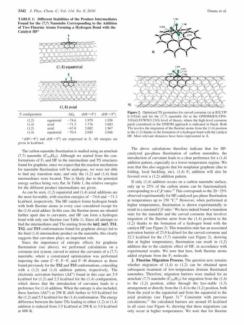
If only (1,4) addition occurs on a carbon nanotube surface,only up to 25% of the carbon atoms can be functionalized,corresponding to a C4F ratio.37 This corresponds to the 20-25%observed experimentally for HF-catalyzed gas-phase fluorinationat temperatures up to 150 °C.51 However, when performed athigher temperatures, fluorination is shown experimentally toresult in a maximal C2F ratio.1 We have indeed found a transitionstate for the nanotube and the curved coronene that involvesmigration of the fluorine atom from the (1,4) position to the(1,2) thanks to the formation of a hydrogen bond with thecatalyst HF (see Figure 2). This transition state has an associatedactivation barrier of 23.0 kcal/mol for the curved coronene and22.2 kcal/mol for the (7,7) nanotube (see Figure 2), showingthat at higher temperatures, fluorination can result in (1,2)addition due to the catalytic effect of HF, in accordance withexperimental results. We note that here, both fluorine atomsadded originate from the F2 molecule.
2. Fluorine Migration Process. The question now remainswhether migration of (1,4) to (1,2) can be obtained uponsubsequent treatment of low-temperature domain fluorinatednanotubes. Therefore, migration barriers were studied for anarmchair (7,7) nanotube (C264H24) for migration from the (1,4)to the (1,2) position, either through the less-stable (1,3)arrangement or directly from the (1,4) to the (1,2) position, bothfrom the axial to the equatorial and from the equatorial to theaxial positions (see Figure 3).52 Consistent with previouscalculations,37 the calculated barriers are around 45 kcal/molin all cases (see Figure 4), showing that these migrations canonly occur at higher temperatures. We note that for fluorine
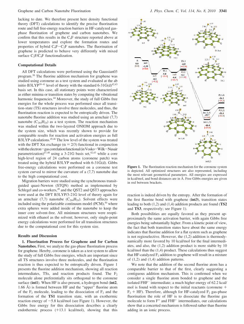
TABLE 1: Different Stabilities of the Product IntermediatesFound for the (7,7) Nanotube Corresponding to the Additionof Two Fluorine Atoms Forming a Hydrogen Bond with theCatalyst HFa
F configuration ∆ER d(H · · ·F1) d(H · · ·F2)
(1,2) equatorial -74.6 1.979 1.958(1,4) axial -71.3 1.776 3.683(1,2) axial -67.0 2.002 1.967(1,4) equatorial -70.4 2.045 2.046
a d(H · · ·F1) and d(H · · ·F2) are expressed in Å. All energies aregiven in kcal/mol.
Figure 2. Optimized TS geometries for curved coronene (a) at B3LYP/6-31G(d) and for the (7,7) nanotube (b) at the ONIOM(B3LYP/6-31G(d):SVWN/3-21G) level of theory, where the high-level coronenepatch considered in the ONIOM approach is indicated in black. BothTSs involve the migration of the fluorine atoms from the (1,4) positionto the (1,2) thanks to the formation of a hydrogen bond with the catalystHF. Most relevant distances have been represented in Å.
3342 J. Phys. Chem. C, Vol. 114, No. 8, 2010 Osuna et al.
migration from the (1,6) to the (1,4) position, we found acomparable activation barrier of 47 kcal/mol.
These migration barriers suggest that upon higher-temperaturetreatment, fluorine added via a (1,4) addition pattern at lowertemperature will surface migrate into a denser packing associatedwith fluorine in (1,2) addition sites. This densification willeventually result in the close-packed maximal addition of a C2Fratio. At lower temperatures, the surface migration cannot occur,and fluorination will be restricted to a maximal uniform coverageof C4F, corresponding to a self-organized addition pattern wherenonfluorinated benzenoid rings are surrounded by fluorine atomsin only the (1,4) position.
The above results have important implications for theproduction of new hybrid carbon nanotube fluorides, which havenot been studied previously. By selecting the fluorinationtemperature and subsequent heating, with optionally makingrepeated fluorination steps, it should be possible to producecarbon nanotubes with alternating bands of pristine C4F or C2Fmaterial. For example, fluorinating at low temperatures to givecomplete C4F coverage, followed by heat treatment (resultingin alternating pristine and C2F bands), followed by repeat
fluorination at room temperature, should result in nanotubes withalternating C4F-C2F bands.
At first sight, the above results may seem contradictory withthe observation of fluorine banding by STM at fluorinationtemperatures up to 150 °C, where C2F-fluorinated circumfer-ential bands are alternated with pristine nanotube parts.34 Thisaddition pattern could only correspond to the above-described(1,4) addition mechanism if migration of the fluorine atoms hasoccurred after the fluorination process. Previous preliminarycalculations suggested that this could result from solubilizationof the C4F-fluorinated nanotubes, where the fluorine migrationbarriers are lowered through hydrogen bonding with thesolvent.37 We therefore repeated the migration barrier calcula-tions using ethanol as the solvent. These calculations show adecrease in the electronic migration barriers from 11 to 4 kcal/mol in the presence of solvent, depending on the case (see Figure4). However, if an explicit ethanol molecule is taken intoaccount, the migration barrier lowers by 10 kcal/mol, showingthat solubilization of the nanotubes in alcohol will indeed helpthe fluorine migration over the surface to a more stable (1,2)addition pattern. We note that entropic effects were not takeninto account here and that only one ethanol molecule wasconsidered, whereas multiple ethanol molecules can surroundthe migrating fluorine atom. A more important lowering of themigration barriers upon solubilization can thus be expected.Migration will also be driven by the reduction of the strainoccurring between fluorinated and unfluorinated bands.35 Inaddition, if an explicit ethanol molecule is taken into accountfor the TS of Figure 2a, the activation barrier of 23.0 kcal/molis reduced by 11.6 kcal/mol, leaving the migration barrier atonly 11.40 kcal/mol. The above results also indicate that bandednanotubes can be obtained either upon subsequent heat treatmentof nanotubes fluorinated at lower temperature or by solubili-zation. Solubilization of these nanotubes will therefore lead toa material with different addition patterns than the originalfluorinated nanotubes.
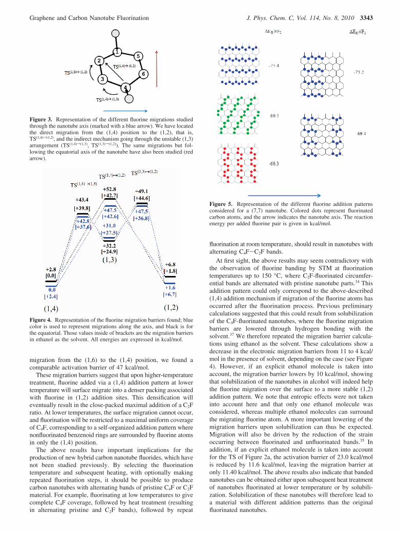
Figure 3. Representation of the different fluorine migrations studiedthrough the nanotube axis (marked with a blue arrow). We have locatedthe direct migration from the (1,4) position to the (1,2), that is,TS(1,4)f(1,2), and the indirect mechanism going through the unstable (1,3)arrangement (TS(1,4)f(1,3), TS(1,3)f(1,2)). The same migrations but fol-lowing the equatorial axis of the nanotube have also been studied (redarrow).
Figure 4. Representation of the fluorine migration barriers found; bluecolor is used to represent migrations along the axis, and black is forthe equatorial. Those values inside of brackets are the migration barriersin ethanol as the solvent. All energies are expressed in kcal/mol.
Figure 5. Representation of the different fluorine addition patternsconsidered for a (7,7) nanotube. Colored dots represent fluorinatedcarbon atoms, and the arrow indicates the nanotube axis. The reactionenergy per added fluorine pair is given in kcal/mol.
Graphene and Carbon Nanotube Fluorination J. Phys. Chem. C, Vol. 114, No. 8, 2010 3343
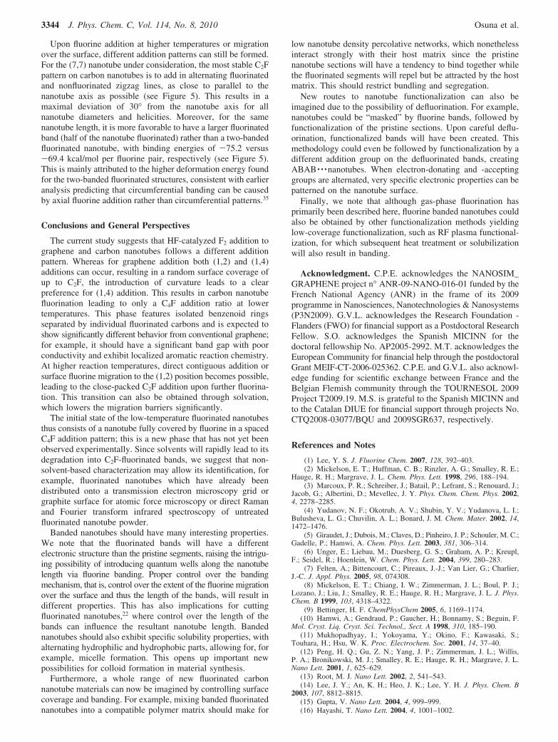
Upon fluorine addition at higher temperatures or migrationover the surface, different addition patterns can still be formed.For the (7,7) nanotube under consideration, the most stable C2Fpattern on carbon nanotubes is to add in alternating fluorinatedand nonfluorinated zigzag lines, as close to parallel to thenanotube axis as possible (see Figure 5). This results in amaximal deviation of 30° from the nanotube axis for allnanotube diameters and helicities. Moreover, for the samenanotube length, it is more favorable to have a larger fluorinatedband (half of the nanotube fluorinated) rather than a two-bandedfluorinated nanotube, with binding energies of -75.2 versus-69.4 kcal/mol per fluorine pair, respectively (see Figure 5).This is mainly attributed to the higher deformation energy foundfor the two-banded fluorinated structures, consistent with earlieranalysis predicting that circumferential banding can be causedby axial fluorine addition rather than circumferential patterns.35
Conclusions and General Perspectives
The current study suggests that HF-catalyzed F2 addition tographene and carbon nanotubes follows a different additionpattern. Whereas for graphene addition both (1,2) and (1,4)additions can occur, resulting in a random surface coverage ofup to C2F, the introduction of curvature leads to a clearpreference for (1,4) addition. This results in carbon nanotubefluorination leading to only a C4F addition ratio at lowertemperatures. This phase features isolated benzenoid ringsseparated by individual fluorinated carbons and is expected toshow significantly different behavior from conventional graphene;for example, it should have a significant band gap with poorconductivity and exhibit localized aromatic reaction chemistry.At higher reaction temperatures, direct contiguous addition orsurface fluorine migration to the (1,2) position becomes possible,leading to the close-packed C2F addition upon further fluorina-tion. This transition can also be obtained through solvation,which lowers the migration barriers significantly.
The initial state of the low-temperature fluorinated nanotubesthus consists of a nanotube fully covered by fluorine in a spacedC4F addition pattern; this is a new phase that has not yet beenobserved experimentally. Since solvents will rapidly lead to itsdegradation into C2F-fluorinated bands, we suggest that non-solvent-based characterization may allow its identification, forexample, fluorinated nanotubes which have already beendistributed onto a transmission electron microscopy grid orgraphite surface for atomic force microscopy or direct Ramanand Fourier transform infrared spectroscopy of untreatedfluorinated nanotube powder.
Banded nanotubes should have many interesting properties.We note that the fluorinated bands will have a differentelectronic structure than the pristine segments, raising the intrigu-ing possibility of introducing quantum wells along the nanotubelength via fluorine banding. Proper control over the bandingmechanism, that is, control over the extent of the fluorine migrationover the surface and thus the length of the bands, will result indifferent properties. This has also implications for cuttingfluorinated nanotubes,22 where control over the length of thebands can influence the resultant nanotube length. Bandednanotubes should also exhibit specific solubility properties, withalternating hydrophilic and hydrophobic parts, allowing for, forexample, micelle formation. This opens up important newpossibilities for colloid formation in material synthesis.
Furthermore, a whole range of new fluorinated carbonnanotube materials can now be imagined by controlling surfacecoverage and banding. For example, mixing banded fluorinatednanotubes into a compatible polymer matrix should make for
low nanotube density percolative networks, which nonethelessinteract strongly with their host matrix since the pristinenanotube sections will have a tendency to bind together whilethe fluorinated segments will repel but be attracted by the hostmatrix. This should restrict bundling and segregation.
New routes to nanotube functionalization can also beimagined due to the possibility of defluorination. For example,nanotubes could be “masked” by fluorine bands, followed byfunctionalization of the pristine sections. Upon careful deflu-orination, functionalized bands will have been created. Thismethodology could even be followed by functionalization by adifferent addition group on the defluorinated bands, creatingABAB · · ·nanotubes. When electron-donating and -acceptinggroups are alternated, very specific electronic properties can bepatterned on the nanotube surface.
Finally, we note that although gas-phase fluorination hasprimarily been described here, fluorine banded nanotubes couldalso be obtained by other functionalization methods yieldinglow-coverage functionalization, such as RF plasma functional-ization, for which subsequent heat treatment or solubilizationwill also result in banding.
Acknowledgment. C.P.E. acknowledges the NANOSIM_GRAPHENE project n° ANR-09-NANO-016-01 funded by theFrench National Agency (ANR) in the frame of its 2009programme in Nanosciences, Nanotechnologies & Nanosystems(P3N2009). G.V.L. acknowledges the Research Foundation -Flanders (FWO) for financial support as a Postdoctoral ResearchFellow. S.O. acknowledges the Spanish MICINN for thedoctoral fellowship No. AP2005-2992. M.T. acknowledges theEuropean Community for financial help through the postdoctoralGrant MEIF-CT-2006-025362. C.P.E. and G.V.L. also acknowl-edge funding for scientific exchange between France and theBelgian Flemish community through the TOURNESOL 2009Project T2009.19. M.S. is grateful to the Spanish MICINN andto the Catalan DIUE for financial support through projects No.CTQ2008-03077/BQU and 2009SGR637, respectively.
References and Notes
(1) Lee, Y. S. J. Fluorine Chem. 2007, 128, 392–403.(2) Mickelson, E. T.; Huffman, C. B.; Rinzler, A. G.; Smalley, R. E.;
Hauge, R. H.; Margrave, J. L. Chem. Phys. Lett. 1998, 296, 188–194.(3) Marcoux, P. R.; Schreiber, J.; Batail, P.; Lefrant, S.; Renouard, J.;
Jacob, G.; Albertini, D.; Mevellec, J. Y. Phys. Chem. Chem. Phys. 2002,4, 2278–2285.
(4) Yudanov, N. F.; Okotrub, A. V.; Shubin, Y. V.; Yudanova, L. I.;Bulusheva, L. G.; Chuvilin, A. L.; Bonard, J. M. Chem. Mater. 2002, 14,1472–1476.
(5) Giraudet, J.; Dubois, M.; Claves, D.; Pinheiro, J. P.; Schouler, M. C.;Gadelle, P.; Hamwi, A. Chem. Phys. Lett. 2003, 381, 306–314.
(6) Unger, E.; Liebau, M.; Duesberg, G. S.; Graham, A. P.; Kreupl,F.; Seidel, R.; Hoenlein, W. Chem. Phys. Lett. 2004, 399, 280–283.
(7) Felten, A.; Bittencourt, C.; Pireaux, J.-J.; Van Lier, G.; Charlier,J.-C. J. Appl. Phys. 2005, 98, 074308.
(8) Mickelson, E. T.; Chiang, I. W.; Zimmerman, J. L.; Boul, P. J.;Lozano, J.; Liu, J.; Smalley, R. E.; Hauge, R. H.; Margrave, J. L. J. Phys.Chem. B 1999, 103, 4318–4322.
(9) Bettinger, H. F. ChemPhysChem 2005, 6, 1169–1174.(10) Hamwi, A.; Gendraud, P.; Gaucher, H.; Bonnamy, S.; Beguin, F.
Mol. Cryst. Liq. Cryst. Sci. Technol., Sect. A 1998, 310, 185–190.(11) Mukhopadhyay, I.; Yokoyama, Y.; Okino, F.; Kawasaki, S.;
Touhara, H.; Hsu, W. K. Proc. Electrochem. Soc. 2001, 14, 37–40.(12) Peng, H. Q.; Gu, Z. N.; Yang, J. P.; Zimmerman, J. L.; Willis,
P. A.; Bronikowski, M. J.; Smalley, R. E.; Hauge, R. H.; Margrave, J. L.Nano Lett. 2001, 1, 625–629.
(13) Root, M. J. Nano Lett. 2002, 2, 541–543.(14) Lee, J. Y.; An, K. H.; Heo, J. K.; Lee, Y. H. J. Phys. Chem. B
2003, 107, 8812–8815.(15) Gupta, V. Nano Lett. 2004, 4, 999–999.(16) Hayashi, T. Nano Lett. 2004, 4, 1001–1002.
3344 J. Phys. Chem. C, Vol. 114, No. 8, 2010 Osuna et al.
(17) Hayashi, T.; Terrones, M.; Scheu, C.; Kim, Y. A.; Ruhle, M.;Nakajima, T.; Endo, M. Nano Lett. 2002, 2, 491–496.
(18) Khabashesku, V. N.; Margrave, J. L.; Barrera, E. V. Diamond Relat.Mater. 2005, 14, 859–866.
(19) Owens, F. J. J. Mater. Chem. 2006, 16, 505–508.(20) Sato, Y.; Ootsubo, M.; Yamamoto, G.; Van Lier, G.; Terrones,
M.; Hashiguchi, S.; Kimura, H.; Okubo, A.; Motomiya, K.; Jeyadevan, B.;Hashida, T.; Tohji, K. ACS Nano 2008, 2, 348–356.
(21) Sato, Y.; Yokoyama, A.; Kasai, T.; Hashiguchi, S.; Ootsubo, M.;Ogino, S. I.; Sashida, N.; Namura, M.; Motomiy, K.; Jeyadevan, B.; Tohji,K. Carbon 2008, 46, 1927–1934.
(22) Gu, Z.; Peng, H.; Hauge, R. H.; Smalley, R. E.; Margrave, J. L.Nano Lett. 2002, 2, 1009–1013.
(23) Charlier, J. C.; Blase, X.; Roche, S. ReV. Mod. Phys. 2007, 79,677–732.
(24) Dettlaff-Weglikowska, U.; Skakalova, V.; Meyer, J.; Cech, J.;Mueller, B. G.; Roth, S. Curr. Appl. Phys. 2007, 7, 42–46.
(25) Bettinger, H. F. ChemPhysChem 2003, 4, 1283–1289.(26) Seifert, G.; Kohler, T.; Frauenheim, T. Appl. Phys. Lett. 2000, 77,
1313–1315.(27) Nakajima, T. J. Fluorine Chem. 1999, 100, 57–61.(28) Worsley, K. A.; Ramesh, P.; Mandal, S. K.; Niyogi, S.; Itkis, M. E.;
Haddon, R. C. Chem. Phys. Lett. 2007, 445, 51–56.(29) Mori, T.; Kikuzawa, Y.; Takeuchi, H. Org. Electron. 2008, 9, 328–
332.(30) Giraudet, J.; Claves, D.; Guerin, K.; Dubois, M.; Houdayer, A.;
Masin, F.; Hamwi, A. J. Power Sources 2007, 173, 592–598.(31) Bloemink, H. I.; Cooke, S. A.; Holloway, J. H.; Legon, A. C.
Angew. Chem., Int. Ed. Engl. 1997, 36, 1340–1342.(32) Lee, Y. S.; Cho, T. H.; Lee, B. K.; Rho, J. S.; An, K. H.; Lee,
Y. H. J. Fluorine Chem. 2003, 120, 99–104.(33) Khabashesku, V. N.; Billups, W. E.; Margrave, J. L. Acc. Chem.
Res. 2002, 35, 1087–1095.(34) Kelly, K. F.; Chiang, I. W.; Mickelson, E. T.; Hauge, R. H.;
Margrave, J. L.; Wang, X.; Scuseria, G. E.; Radloff, C.; Halas, N. J. Chem.Phys. Lett. 1999, 313, 445–450.
(35) Van Lier, G.; Ewels, C. P.; Zuliani, F.; De Vita, A.; Charlier, J. C.J. Phys. Chem. B 2005, 109, 6153–6158.
(36) Osuna, S.; Torrent-Sucarrat, M.; Ewels, C. P.; Sola, M.; Geerlings,P.; Van Lier, G. J. Nanosci. Nanotechnol. 2009, 9, 6078–6083.
(37) Ewels, C. P.; Van Lier, G.; Charlier, J. C.; Heggie, M. I.; Briddon,P. R. Phys. ReV. Lett. 2006, 96, 216103 (1-4).
(38) Frisch, M. J.; Trucks, G. W.; Schlegel, H. B.; Scuseria, G. E.; Robb,M. A.; Cheeseman, J. R.; Montgomery, J. A., Jr.; Vreven, T.; Kudin, K. N.;Burant, J. C.; Millam, J. M.; Iyengar, S. S.; Tomasi, J.; Barone, V.;Mennucci, B.; Cossi, M.; Scalmani, G.; Rega, N.; Petersson, G. A.;Nakatsuji, H.; Hada, M.; Ehara, M.; Toyota, K.; Fukuda, R.; Hasegawa, J.;Ishida, M.; Nakajima, T.; Honda, Y.; Kitao, O.; Nakai, H.; Klene, M.; Li,
X.; Knox, J. E.; Hratchian, H. P.; Cross, J. B.; Bakken, V.; Adamo, C.;Jaramillo, J.; Gomperts, R.; Stratmann, R. E.; Yazyev, O.; Austin, A. J.;Cammi, R.; Pomelli, C.; Ochterski, J. W.; Ayala, P. Y.; Morokuma, K.;Voth, G. A.; Salvador, P.; Dannenberg, J. J.; Zakrzewski, V. G.; Dapprich,S.; Daniels, A. D.; Strain, M. C.; Farkas, O.; Malick, D. K.; Rabuck, A. D.;Raghavachari, K.; Foresman, J. B.; Ortiz, J. V.; Cui, Q.; Baboul, A. G.;Clifford, S.; Cioslowski, J.; Stefanov, B. B.; Liu, G.; Liashenko, A.; Piskorz,P.; Komaromi, I.; Martin, R. L.; Fox, D. J.; Keith, T.; Al-Laham, M. A.;Peng, C. Y.; Nanayakkara, A.; Challacombe, M.; Gill, P. M. W.; Johnson,B.; Chen, W.; Wong, M. W.; Gonzalez, C.; Pople, J. A. Gaussian 03,revision C.01; Gaussian, Inc.: Pittsburgh, PA, 2003.
(39) Becke, A. D. J. Chem. Phys. 1993, 98, 5648–5652.(40) Lee, C.; Yang, W.; Parr, R. G. Phys. ReV. B 1988, 37, 785–789.(41) Stephens, P. J.; Devlin, F. J.; Chabalowski, C. F.; Frisch, J. M. J.
Phys. Chem. 1994, 98, 11623–11627.(42) Hariharan, P. C.; Pople, J. A. Theor. Chim. Acta 1973, 28, 213–
222.(43) Hehre, W. J.; Ditchfie, R.; Pople, J. A. J. Chem. Phys. 1972, 56,
2257–2261.(44) All transition states here were characterized by computing the
analytical vibrational frequencies to have one (and only one) imaginaryfrequency corresponding to the approach of both reacting molecules. Anintrinsic reaction coordinate (IRC) study was also performed to ensure thatall TSs located were connecting the expected reactants and products.
(45) Osuna, S.; Houk, K. N. Chem. Eur. J. 2009, 15, 13219–13231.(46) Osuna, S.; Morera, J.; Cases, M.; Morokuma, K.; Sola, M. J. Phys.
Chem. A 2009, 113, 9721–9726.(47) Slater, J. C. Quantum Theory of Molecules and Solids; McGraw-
Hill: New York, 1974; Vol. 4.(48) Vosko, S. H.; Wilk, L.; Nusair, M. Can. J. Phys. 1980, 58, 1200–
1211.(49) Peng, C.; Ayala, P. Y.; Schlegel, H. B.; Frisch, J. M. J. Comput.
Chem. 1996, 17, 49–56.(50) Tomasi, J.; Mennucci, B.; Cammi, R. Chem. ReV. 2005, 105, 2999.(51) An, K. H.; Heo, J. G.; Jeon, K. G.; Bae, D.; Jo, C. S.; Yang, C. W.;
Park, C. Y.; Lee, Y. H.; Lee, Y. S.; Chung, Y. S. Appl. Phys. Lett. 2002,80, 4235–4237.
(52) Our B3LYP/3-21G calculations predict the (1,4) final additionproduct as the most favorable product by approximately 2 kcal/mol, whereasour previous ONIOM calculations indicate that the (1,2) adduct wasthermodynamically the most favorable product by approximately 3 kcal/mol. The slight difference in stability between different (1,2) and (1,4)adducts is likely to change with the method/basis set considered. Althoughthe basis set used for the study of the migration is quite small, a qualitativedescription of the process is still possible.
JP908887N
Graphene and Carbon Nanotube Fluorination J. Phys. Chem. C, Vol. 114, No. 8, 2010 3345