Embed Size (px)
Citation preview

ZR Series with Lutron EcoSystem Controls Specification Troffers with Removable Lens
Includes: ZR14-LDE1/LDE5, ZR22-LDE1/LDE5, ZR24-LDE1/LDE5
1 of 3 LPN00678X0005A0_B
INSTALLATION INSTRUCTIONSINSTRUCTIONS D’INSTALLATION
TO INSTALL:
T- BAR CEILING MOUNTING
STEP 1:Bring the ZR troffer into the T-bar ceiling panel. See Figure 1 for location of the T-bar clips on end panels of troffer.
STEP 2:Bend clips upward and rotate outward to engage with T-bar support grid. See Figure 2. Secure luminaire to grid in compliance with state and local codes.
1
ZR14-LDE1/LDE5
ZR22-LDE1/LDE5
ZR24-LDE1/LDE5
• The ZR-LDE1/LDE5 Series of recessed troffers is for non-insulated ceiling applications using T-Bar ceiling grid, drywall grid adaptors, and suspended mount.
• Designed for use in 120-277V 50-60 Hz protected circuit (fuse box, circuit breaker). Supply wire sized as per NEC or governing code(s), 90C rated.
• Make sure to cap off all unused leads.
• Lens and removable end cap may shift during installation. Press center of lens to engage magnet strip and push the end cap against the end panel to eliminate the gap after installation.
• IMPORTANT: To avoid damage to the lens or housing during installation, make sure fixture is supported near the centers of both long sides of the housing when lifting. Do not lift fixture from one end only.
T-Bar Clips
T-Bar Clip Hole
IMPORTANT SAFEGUARDSWhen using electrical equipment, basic safety precautions should always be followed including the following:
READ AND FOLLOW ALL SAFETY INSTRUCTIONS
1. DANGER- Risk of shock- Disconnect power before installation.DANGER – Risque de choc – Couper l’alimentation avant l’installation.
2. This luminaire must be installed in accordance with the NEC or your local electrical code. If you are not familiar with these codes and requirements, consult a qualified electrician. Ce produit doit être installé conformément à NEC ou votre code électrique local. Si vous n’êtes pas familier avec ces codes et ces exigences, veuillez contacter un électricien qualifié.
3. Suitable for Damp Locations. Convient aux emplacements humides.
4. Access above ceiling required. Do not install insulation within 3 inches (76 mm) of any part of the luminaire. Acces requis au-dessus du plafond. Ne pas mettre l’isolant a moins de 76 mm (3 po) de toute partie du luminaire.
5. Vapor barrier must be suitable for 90C. Le pare-vapeur doit convenir pour 90 °C.
6. No user serviceable parts. Pieces non reparables par l’utilisateur.
7. Inherently protected. Protection inherente.
8. Do not handle energized module with wet hands or when standing on wet or damp surfaces, or in water
SAVE THESE INSTRUCTIONS FOR FUTURE REFERENCE

2 of 3 LPN00678X0005A0_B
SUSPENDED MOUNTING
STEP 1:Attach customer supplied cables to the (4) T-bar clips located in the corners of the housing. See Figure 1. NOTE: The hole in each clip should be used to attach the cable
STEP 2:Attach cables to mounting surface using customer supplied hardware. Ensure that mounting surface can support the luminaire.
WIRING AND DIMMING OPTION
STEP 1:Remove the screw on the cover of the junction box and bring in appropriate power supply to the junction box using one of the knock-outs. See Figure 3 and 4.
STEP 2:Bring dimming conduit into dimming wire compartment using one of the knock-outs on the dimming side of the junction box. See Figure 4 .
STEP 3:Wire luminaire per “Electrical Connections” section and push all leads into the junction box. Reattach junction box cover that was removed in Step 1. Make sure no wires are pinched.
CLEANING LENS
STEP 1:Locate the end cap with the arrow marks on it, indicating that the end cap is removable. See Figure 5.
STEP 2:Grab the lens section next to the end cap and pull lens and end cap together downward gently until end cap just clears luminaire (about 3” to 4” from original position). See Figure 6.
STEP 3:Disengage the other end of the lens from the opposite end cap by pulling lens away from end cap. See Figure 6. Once lens is removed, perform cleaning.
STEP 4:
After cleaning is complete insert lens back into fixed end cap. Push the removable end cap upward into the housing and using a gentle rocking motion engage the end cap to retention clip. Check removable end cap for any visible gap between the end cap and end panel. If necessary push end cap against the end panel to eliminate gaps.Check lens for any visible gap between the lens and luminaire. If necessary push lens upward at gap location to seal magnetic foam to luminaire. See Figure 7.
5
End Cap
Arrow Marks
7
Arrow Marked End Cap
DO NOT Rotate Lens Into This
Zone
6 1
2
Fixed End Cap
12
2
T-Bar Clips bent upward, rotated outward, and engaged with the grid
Junction Box Cover
3
� �� �� �� �� ��� � ��� � �
4AC Wiring Chamber
Dimming Wiring Chamber

3 of 3 LPN00678X0005A0_B
www.creelighting.com
© 2020 Cree Lighting, A company of IDEAL INDUSTRIES. All rights reserved. For informational purposes only. Content is subject to change. See www.creelighting.com/warranty for warranty and specifications. Cree® and the Cree logo are registered trademarks of Cree, Inc. SmartCast®, is a registered trademark and ZR14™, ZR22™ and ZR24™ are trademarks of Cree Lighting, A company of IDEAL INDUSTRIES.
ELECTRICAL CONNECTIONS
STEP 1:
For 120/277V applications make the following Electrical Connections:
a. Connect the black luminaire lead to the supply lead.
b. Connect the white luminaire lead to the neutral supply lead.
c. Connect the green or green/yellow ground lead to the green supply lead.
For 208/240V applications, make the following Electrical Connections:
a. Connect Hot 1 supply lead to the black lead.b. Connect Hot 2 supply lead to the white lead c. Connect the green or green/yellow ground lead to the
supply ground lead.
STEP 2:
If dimming is being used, for E1/E2 connection, refer to Lutron application note #142 (P/N 048162), Ecosystem bus Class 1 and Class 2 listing at www.lutron.com for more information on wiring options. If dimming is not being used, ensure to cap off the lead.
LINE OR HOT 1
E2 (VIOLET)E1
(VIOLET/WHITE)
DRIVER ASSEMBLY
BLACK
WHITENEUTRAL OR HOT 2
TO E
CO
SYSTE
MD
IGITA
L LINK
FCC NOTICE
CAUTION: Changes or modifications not expressly approved could void your authority to use this equipment.
This device complies with Part 15 of the FCC Rules. Operation to the following two conditions: (1) This device may not cause harmful interference, and (2) this device must accept any interference received, including interference that may cause undesired operation.
This device has been tested and found to comply with the limits for a Class A digital device, pursuant to Part 15 of the FCC Rules. These limits are designed to provide reasonable protection against harmful interference when the device is operated in a commercial environment. This device generates, uses, and can radiate radio frequency energy and, if not installed and used in accordance with the instruction manual, may cause harmful interference to radio communications. Operation of this device in a residential area is likely to cause harmful interference in which case the user will be required to correct the interference at his own expense.
INDUSTRY CANADA STATEMENT
This device complies with Industry Canada licence-exempt RSS standard(s). Operation is subject to the following two conditions: (1) this device may not cause interference, and (2) this device must accept any interference, including interference that may cause undesired operation of the device. In addition, this device complies with ICES-005 of the Industry Canada (IC) Regulations.
Le présent appareil est conforme aux CNR d’Industrie Canada applicables aux appareils radio exempts de licence. L’exploitation est autorisée aux deux conditions suivantes : (1) l’appareil ne doit pas produire de brouillage, et (2) l’utilisateur de l’appareil doit accepter tout brouillage radioélectrique subi, même si le brouillage est susceptible d’en compromettre le fonctionnement.

Serie ZR con controles Lutron EcoSystem
Especificación de luminarias fluorescentes con lentes removibles Incluye: ZR14-LDE1/LDE5, ZR22-LDE1/LDE5, ZR24-LDE1/LDE5
1 de 3 LPN00678X0005A0_B
INSTRUCCIONES DE INSTALACIÓNINSTRUCTIONS D’INSTALLATION
PARA INSTALAR:
MONTAJE EN CIELORRASO CON BARRA EN T
PASO 1:Coloque la luminaria ZR en el panel de cielo raso de barra en T. Consulte la Figura 1 para ver la ubicación de los clips de la barra en T en los paneles finales de la luminaria.
PASO 2:Doble los clips hacia arriba y gire hacia afuera para enganchar con la barra en T de la rejilla de soporte. Consulte la Figura 2. Asegure la luminaria a la rejilla conforme a los códigos estatales y locales.
1
ZR14-LDE1/LDE5
ZR22-LDE1/LDE5
ZR24-LDE1/LDE5
• La Serie ZR-LDE1/LDE5 de luminarias fluorescentes empotradas se usan para aplicaciones de techo no aisladas que usan rejilla de techo con barra en T, adaptadores de rejilla de yeso y montaje suspendido.
• Este producto está diseñado para usarse en circuitos protegidos de 120-277 V 50-60 Hz (caja de fusibles, disyuntor). Suministre el cable del tamaño según el NEC o los códigos normativos, con clasificación 90C.
• Asegúrese de cubrir todos los cables no utilizados.
• El lente y el tapón extraíble pueden cambiar durante la instalación. Presione el centro del lente para enganchar la tira magnética y empuje el tapón contra el panel final para eliminar el espacio después de la instalación.
• IMPORTANTE: Para evitar dañar los lentes o la carcasa durante la instalación, asegúrese de que el dispositivo esté colocado cerca de los centros de ambos laterales largos de la carcasa al levantarlo. No levante la carcasa de un solo extremo.
Clips de la barra en T
Orificio del clip de la barra en T
MEDIDAS DE SEGURIDAD IMPORTANTESAl usar aparatos eléctricos, siempre deben seguirse ciertas medidas básicas de seguridad, incluidas las siguientes:
LEA Y SIGA TODAS LAS INSTRUCCIONES DE SEGURIDAD
1. PELIGRO: Riesgo de descarga eléctrica. Desconecte la alimentación eléctrica antes de la instalación.DANGER – Risque de choc – Couper l’alimentation avant l’installation.
2. Esta luminaria debe instalarse de acuerdo con el Código Eléctrico de Estados Unidos (NEC, por sus siglas en inglés) o con el código eléctrico local. Si no está familiarizado con estos códigos y requisitos, consulte a un electricista califi cado. Ce produit doit être installé conformément à NEC ou votre code électrique local. Si vous n’êtes pas familier avec ces codes et ces exigences, veuillez contacter un électricien qualifi é.
3. Este producto es adecuado para uso en lugares húmedos. Convient aux emplacements humides.
4. Es necesario un acceso por encima del cielo raso. No instalar aislamiento dentro de las 3 pulgadas (76 mm) de cualquier parte de la luminaria. Acces requis au-dessus du plafond. Ne pas mettre l’isolant a moins de 76 mm (3 po) de toute partie du luminaire.
5. La barrera de vapor debe ser adecuada para 90 °C. Le pare-vapeur doit convenir pour 90 °C.
6. No hay piezas que puedan ser reparadas por el usuario. Pieces non reparables par l’utilisateur.
7. Inherentemente protegidas. Protection inherente.
8. No manipular el módulo energizado con las manos húmedas o cuando se esté parado sobre superfi cies mojadas o húmedas, o en el agua.
CONSERVE ESTAS INSTRUCCIONES PARA CONSULTAS POSTERIORES

2 de 3 LPN00678X0005A0_B
MONTAJE COLGANTE
PASO 1:Fije los cables suministrados por el cliente en los (4) clips de la barra en T ubicados en las esquinas de la carcasa. Consulte la Figura 1. NOTA: El orificio en cada clip se debe usar para fijar el cable.
PASO 2:Fije los cables a la superficie de montaje usando los accesorios suministrados por el cliente. Asegúrese de que la superficie de montaje pueda soportar la luminaria.
CABLEADO Y OPCIÓN DE ATENUACIÓN
PASO 1:Retire el tornillo de la tapa de la caja de conexiones y suministre alimentación eléctrica adecuada a la caja de conexiones usando uno de los orificios precortados. Consulte las Figuras 3 y 4.
PASO 2:Coloque el conducto para el atenuador en el compartimiento de cableado del atenuador usando uno de los orificios precortados en el
lado del atenuador de la caja de conexiones. Consulte la Figura 4.
PASO 3:Realice las conexiones eléctricas de la luminaria conforme a la sección “Conexiones eléctricas” y empuje todos los cables dentro de la caja de conexiones. Vuelva a instalar la tapa de la caja de conexiones que retiró en el paso 1. Asegúrese de no pellizcar ningún cable.
LIMPIEZA DEL LENTE
PASO 1:Ubique el tapón con la flecha marcada que indica que el tapón es extraíble. Consulte la Figura 5.
PASO 2:Sujete la sección del lente junto al tapón y tire suavemente del lente y el tapón juntos hacia abajo hasta que el tapón apenas salga de la luminaria (alrededor de 3 o 4 pulgadas de la posición original). Consulte la Figura 6.
PASO 3:Desenganche del tapón el extremo opuesto del lente tirando del lente. Consulte la Figura 6. Una vez que lo haya extraído, límpielo.
PASO 4:Después de limpiarlo, vuelva a insertar el lente en el tapón fijo. Empuje el tapón extraíble hacia arriba dentro de la carcasa y con un movimiento de balanceo suave, enganche la tapa del extremo al clip de retención. Revise el tapón para ver si hay algún espacio visible entre el tapón y el panel final. De ser necesario, empuje el tapón contra el panel final para eliminar los espacios.Revise el lente para ver si hay algún espacio visible entre el lente y la luminaria. De ser necesario, empuje el lente hacia arriba en la ubicación del espacio para sellar la espuma magnética en la luminaria. Consulte la Figura 7.
5
Tapón
Marcas de flecha
7
Tapón con marca de flecha
NO gire el lente hacia esta zona
6 1
2
Tapón fijo
12
2
Clips de la barra en T doblados hacia arriba, girados hacia afuera y enganchados con la rejilla
Tapa de la caja de conexiones
3
� �� �� �� �� ��� � ��� � �
4Cámara de cableado de CA
Cámara de cableado del atenuador
3 de 3 LPN00678X0005A0_B
www.creelighting.com
© 2020 Cree Lighting, una empresa de IDEAL INDUSTRIES. Todos los derechos reservados. Para fines informativos únicamente. El contenido está sujeto a cambios. Visite www.creelighting.com/warranty para ver la garantía y las especificaciones. Cree® y el logo de Cree son marcas registradas de Cree, Inc. SmartCast®, es una marca resgistrada y ZR14™, ZR22™ y ZR24™ son marcas de Cree Lighting, una empresa de IDEAL INDUSTRIES.
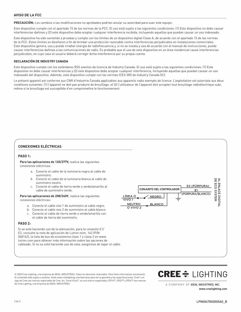
CONEXIONES ELÉCTRICAS
PASO 1:
Para las aplicaciones de 120/277V, realice las siguientes conexiones eléctricas:
a. Conecte el cable de la luminaria negra al cable de suministro.
b. Conecte el cable de la luminaria blanca al cable de suministro neutro.
c. Conecte el cable de tierra verde o verde/amarillo al cable de suministro verde.
Para las aplicaciones de 208/240V, realice las siguientes conexiones eléctricas:
a. Conecte el cable vivo 1 de suministro al cable negro.b. Conecte el cable vivo 2 de suministro al cable blanco. c. Conecte el cable de tierra verde o verde/amarillo con
el cable de tierra del suministro.
PASO 2:
Si se está haciendo uso de la atenuación, para la conexión E1/E2, consulte la nota de aplicación de Lutron núm. 142 (P/N 048162), la lista de bus de ecosistema clase 1 y clase 2 en www.lutron.com para obtener más información sobre las opciones de cableado. Si no se está haciendo uso de esta, asegúrese de tapar el cable.
LÍNEA OVIVO 1
E2 (PÚRPURA)
E1(PÚRPURA/BLANCO)
CONJUNTO DEL CONTROLADOR
NEGRO
BLANCONEUTROO VIVO 2
AL
EN
LA
CE
DIG
ITA
LD
E E
CO
SY
ST
EM
AVISO DE LA FCC
PRECAUCIÓN: Los cambios o las modificaciones no aprobados podrían anular su autoridad para usar este equipo.
Este dispositivo cumple con el apartado 15 de las normas de la FCC. El uso está sujeto a las siguientes condiciones: (1) Este dispositivo no debe causar interferencias dañinas y (2) este dispositivo debe aceptar cualquier interferencia recibida, incluyendo aquellas que puedan causar un uso indeseado.
Este dispositivo ha sido sometido a pruebas y cumple con los límites de un dispositivo digital Clase A, de acuerdo con el apartado 15 de las normas de la FCC. Estos límites se diseñaron a fin de brindar una protección razonable contra interferencias perjudiciales en instalaciones comerciales. Este dispositivo genera, usa y puede irradiar energía de radiofrecuencia y, si no se instala y usa de acuerdo con el manual de instrucciones, puede causar interferencias dañinas a las comunicaciones de radio. Es probable que el uso de este dispositivo en un área residencial cause interferencias perjudiciales, en cuyo caso el usuario deberá corregir dicha interferencia por su propia cuenta.
DECLARACIÓN DE INDUSTRY CANADA
Este dispositivo cumple con los estándares RSS exentos de licencia de Industry Canada. El uso está sujeto a las siguientes condiciones: (1) Este dispositivo no debe causar interferencias y (2) este dispositivo debe aceptar cualquier interferencia, incluyendo aquellas que puedan causar un uso indeseado del dispositivo. Además, este dispositivo cumple con las normas ICES-005 de Industry Canada (IC).
Le présent appareil est conforme aux CNR d’Industrie Canada applicables aux appareils radio exempts de licence. L’exploitation est autorisée aux deux conditions suivantes: (1) l’appareil ne doit pas produire de brouillage, et (2) l’utilisateur de l’appareil doit accepter tout brouillage radioélectrique subi, même si le brouillage est susceptible d’en compromettre le fonctionnement.