Embed Size (px)
Citation preview
Tank Bottom Cathodic Protection System Installation Guide for MATCOR SPL™ Tank Ring Anode System
Page 1 of 4
READ THE FOLLOWING INSTRUCTIONS
CAREFULLY BEFORE PROCEEDING

Tank Bottom Cathodic Protection System Installation Guide for MATCOR SPL™ Tank Ring Anode System
Page 2 of 4
Installation Instructions DISCLAIMER: MATCOR highly recommends that the installation of this system be done by MATCOR or a trained professional familiar with MATCOR products. By not doing so, installer assumes all responsibilities. Upon receipt of the cathodic protection system materials, please follow the Identification, Inspection and Installation information included.
Identification Each cathodic protection system component has been labeled with a distinctive tag/packaging that identifies:
� The system component (i.e. anode, reference electrode, rectifier, etc.).
� The quantity of each system component.
� The amount of lead wire connected to a corresponding component (i.e. anode or reference electrode).
Locate the tag on each of the cathodic protection system component or on the corresponding box/crate and insure that the quantity matches with the information provided (i.e. packing list.) The MATCOR SPL™-Anode may be on multiple reels and the total number of reels will be numbered in sequence. The anode should be pulled from the lowest number reel first (i.e. 1 of 5, the 2 of 5, etc.)
Inspection After it has been determined that the type and quantity of the received system components matches the type and quantity designated in the packing list, inspect the material for the presence of damage that may have occurred during shipment.
Tank Bottom Cathodic Protection System Installation Guide for MATCOR SPL™ Tank Ring Anode System
Page 3 of 4
If you observe damage to any of the materials, inform MATCOR and/or the shipper as soon as possible. DO NOT install any material that you suspect to be damaged.
Anode and Reference Electrode Installation 1. Refer to the installation drawings/calculation
sheets for the tank number, number of reference electrodes, the quantity of anode rings and the spacing of the anode rings.
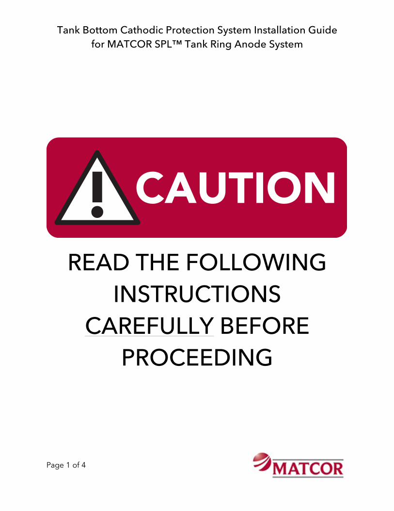
2. Place a stake in the center of the tank (see Photo 1). Measure the distance from the tank center to the first ring as shown on the calculations sheet. Please note that the data sheet shows ring diameter and the measurement from the center stake to the ring location is the radius (for example if the first anode ring diameter is 9 ft then the correct spacing is 4.5 ft from the center stake.) Mark the anode ring location with spray paint or chalk at several locations to facilitate properly locating the anode in a circle.
3. Remove the individual anode ring segments from the shipping reels. Remove any protective material that may have been used solely for shipping purposes. DO NOT USE A KNIFE OR OTHER SHARP OBJECT TO REMOVE ANY TAPE OR PLASTIC WRAP. Utilize caution so as not to damage the anode’s lead wire or the fabric that houses the prepackaged anode.
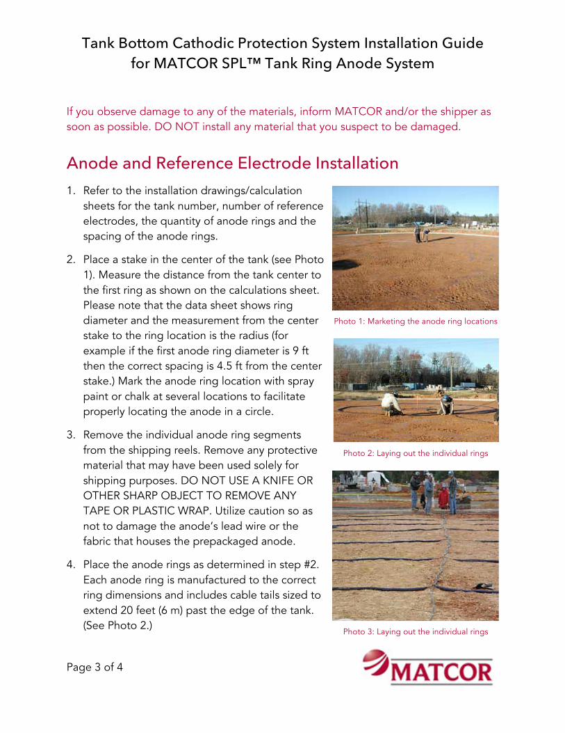
4. Place the anode rings as determined in step #2. Each anode ring is manufactured to the correct ring dimensions and includes cable tails sized to extend 20 feet (6 m) past the edge of the tank. (See Photo 2.)
Photo 1: Marketing the anode ring locations
Photo 2: Laying out the individual rings
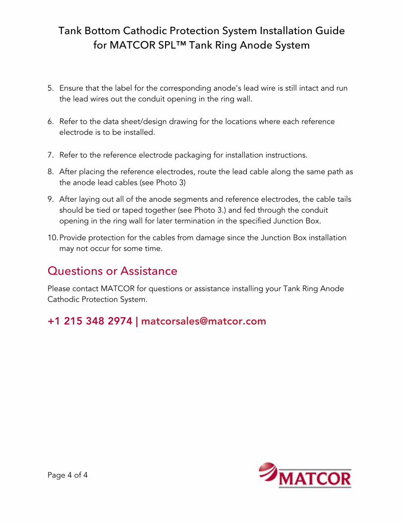
Photo 3: Laying out the individual rings
Tank Bottom Cathodic Protection System Installation Guide for MATCOR SPL™ Tank Ring Anode System
Page 4 of 4
Questions or Assistance Please contact MATCOR for questions or assistance installing your Tank Ring Anode Cathodic Protection System. +1 215 348 2974 | [email protected]
5. Ensure that the label for the corresponding anode’s lead wire is still intact and run the lead wires out the conduit opening in the ring wall.
6. Refer to the data sheet/design drawing for the locations where each reference electrode is to be installed.
7. Refer to the reference electrode packaging for installation instructions.
8. After placing the reference electrodes, route the lead cable along the same path as the anode lead cables (see Photo 3)
9. After laying out all of the anode segments and reference electrodes, the cable tails should be tied or taped together (see Photo 3.) and fed through the conduit opening in the ring wall for later termination in the specified Junction Box.
10. Provide protection for the cables from damage since the Junction Box installation may not occur for some time.