Embed Size (px)
Citation preview

TOPFIRES.COMTHEOUTDOORPLUS.COM
Page 1 P: 909-460-5579F: 909-460-5530
FIRE AND WATER BOWLInstallation Guide & Owners Manual
I N N O V A T O R S I N O U T D O O R P R O D U C T S A N D C O M P O N E N T S
WARNING:Improper installation, adjustment, alteration, service, or maintenance can cause injury or property damage. Read the installation, operating, and maintenance instructions thoroughly before installing or servicing this equipment.
WARNING:Do NOT Store or use gasoline or other flammable vapors and liquids in vicinity of this or any other appliance.An LP cylinder not connected for use shall not be stored in the vicinity of this or any other unit.
WARNING:For use with Natural Gas or Liquid Propane ONLY
NO SOLID FUELS TO BE USED
WARNINGFOR OUTDOOR USE ONLY
CARBON MONOXIDE HAZARDThis appliance can produce carbon monoxide which has no odor.Using it in an enclosed space can kill you.Never use this appliance in an enclosed space such as a camper, tent car or home.
We suggest that our products be serviced by a professional certified in the U.S. By the National Fireplace Institute as a NFI Specialists
Installation: we suggest that our products be installed by professionals that are locally licensed by the authority having jurisdiction in gas piping
Installation must conform with local codes or, in the absence of local codes, with theNational Fuel Gas Code, ANSI Z223.1 / NFPA 54, or International Fuel Gas Code.The appliance, when installed, must be electrically grounded in accordance with local codes or, inthe absence of local codes, with the National Electric Code, ANSI/NFPA 70, if applicable.
TAMPERING, MANIPULATING, AND/OR ALTERATIONS TO THE UNIT WILL VOID THE WARRANTY IMMEDIATELY
*READ THIS MANUAL BEFORE INSTALLATION OF THE UNIT

TOPFIRES.COMTHEOUTDOORPLUS.COM
Page 2 P: 909-460-5579F: 909-460-5530
TABLE OF CONTENTS
WATER ONLY BOWL 3
FIRE ONLY BOWL - MATCH LIT IGNITION 5
FIRE & WATER BOWL - MATCH LIT IGNITION 13
FIRE ONLY BOWL - ELECTRONIC IGNITION 21
FIRE & WATER BOWL - ELECTRONIC IGNITION 32
CLEARANCE FROM COMBUSTIBLES 44
WARRANTY 44

TOPFIRES.COMTHEOUTDOORPLUS.COM
Page 3 P: 909-460-5579F: 909-460-5530
WATER ONLY BOWL INSTALLATION
WARNING:Improper installation, adjustment, alteration, service, or maintenance can cause injury
or property damage. Read the installation, operating, and maintenance instructions thoroughly before installing or servicing this equipment
*READ THIS MANUAL BEFORE INSTALLATION OF THE UNIT
ITEMS INCLUDED:• Copper Spillway
• Concrete Bowl
• Water Fitting
REQUIREMENTS FOR WATER BOWL:• Water flow: 12-15 GPM• Silicone or Epoxy adhesive• Water line or hose• Decorative stones (optional)
1 ½” Threading
Smooth Flow Fitting Copper Spillway
TOPFIRES.COMTHEOUTDOORPLUS.COM
Page 4 P: 909-460-5579F: 909-460-5530
WATER ONLY BOWL INSTALLATION Cont.
Step 3. Leak test. Add small amounts of water in the interior of the bowl to check for leaks. If leak is detected you can patch the leak with more silicone. If no leak is detected you are now ready to install the water supply line.
Step 4. Connect your supply line to the water fitting. The water fitting has 1 ½” female but you can reduce it to your desired water supply line. This fitting is made for an installation of the water bowl and to give you the best flow output possible.
Step 5. Secure the bowl to the column. You can use thin-set, anchors, mortar, cement and or any other bonding agent. If you are using anchors please make sure to pre-drill the bowl to avoid cracking the bowl. Make sure the bowl is water tight. When securing the bowl level the bowl to get an even flow out of the scupper. Not having a level bowl can result in an inconsistent water flow..
Step 6. Install the scupper to the bowl. Per-manently attach the scupper to the lip of the bowl by using an epoxy adhesive, silicone and or any other bonding agent of choice. Make sure the scupper is leveled for the best water flow output.
Step 7. You are now ready to turn on your wa-ter bowl. You can add decorative stone inside the bowl if desired.
Step 1. Install our smooth flow watter fitting. Remove the nut (reverse thread) apply silicone on the interior of the water fitting to avoid water leakage(See Diagram #1)
Step 2. Tighten the smooth flow fitting. Reminder the nut is reverse thread. Allow curring time for the silicone to avoid any water leaks.
WARRANTYLIMITED WARRANTY
The Outdoor Plus Company (TOP) warranties HWI fire bowls against manufacturing defects that prevent safe and correct func-tion as follows:
• Electronics, Gas Valve, & Pilot Assembly: Commercial-6mos; Residential- 1 yr. •Stainless Steel Pan, Fire Ring, & Valve Box: Commercial-1yr.; Residential 3yrs.
This commences from the date of original sale / shipment from The Outdoor Plus. This warranty is for parts and in-house (TOP) labor. The defective product must be sent back to TOP with a Return Merchandise Authorization (RMA) issued by TOP for that specific product and any other additional information for the nature of the defect or warranty claim. The warranty does not cover items that have been damaged by overheating, modification, abuse, or improper storage. Also any labor involving installation or maintenance with the unit is not covered. This warranty excludes claims for consequential, indirect-collateral expenses arising from product defects or warranty recovery.

TOPFIRES.COMTHEOUTDOORPLUS.COM
Page 5 P: 909-460-5579F: 909-460-5530
WARNINGFOR OUTDOOR USE ONLY
*READ THIS MANUAL BEFORE INSTALLATION OF THE UNIT
WARNING:Improper installation, adjustment, alteration, service, or maintenance can cause injury or property damage. Read the installation, operating, and maintenance instructions thoroughly before installing or servicing this equipment.
WARNING:Do NOT Store or use gasoline or other flammable vapors and liquids in vicinity of this or any other appliance.An LP cylinder not connected for use shall not be stored in the vicinity of this or any other unit.
WARNING:For use with Natural Gas or Liquid Propane ONLY
NO SOLID FUELS TO BE USED
CARBON MONOXIDE HAZARDThis appliance can produce carbon monoxide which has no odor.Using it in an enclosed space can kill you.Never use this appliance in an enclosed space such as a camper, tent car or home.
We suggest that our products be serviced by a professional certified in the U.S. By the National Fireplace Institute as a NFI Specialists
Installation: we suggest that our products be installed by professionals that are locally licensed by the authority having jurisdiction in gas piping
Installation must conform with local codes or, in the absence of local codes, with theNational Fuel Gas Code, ANSI Z223.1 / NFPA 54, or International Fuel Gas Code.The appliance, when installed, must be electrically grounded in accordance with local codes or, inthe absence of local codes, with the National Electric Code, ANSI/NFPA 70, if applicable.
TAMPERING, MANIPULATING, AND/OR ALTERATIONS TO THE UNIT WILL VOID THE WARRANTY IMMEDIATELY
FIRE BOWLMATCH LIT IGNITION

TOPFIRES.COMTHEOUTDOORPLUS.COM
Page 6 P: 909-460-5579F: 909-460-5530
Please carefully follow the instructions in this manual to prevent personal injury or property loss. Instructions are updated as needed. It is the installer’s responsibility to periodically review instruction for applicable updates.
The steps listed asWARNING: Contains information critical to the safe installation and operation of the fire bowl.WARRANTY REQUIREMENT: Must be strictly followed to qualify for product warranty.Warranty will be void if not followed.IMPORTANT: Are notes and insights to help ensure product satisfaction and serviceability.WARNING: It is the installer’s responsibility to ensure a safe installation and to educate the end user as to properoperation. Leave this manual with the end user.WARNING: Never alter product or configuration in any way.WARNING: We suggest that our products be installed by professionals that are locally licensed by the authority having jurisdiction in gas piping. We suggest that our products be serviced annually by a professional certified in the US by theNational Fireplace Institute (NFI) as NFI Gas Specialists or in Canada by WETT (Wood Energy Technical Training).Installer must follow all instructions carefully to ensure proper performance and safety.The Outdoor Plus Company is not responsible for your actions.WARNING: Product is not intended to be a starter for wood or any other combustibles.WARNING: Product is not for use with small LP Tanks and must utilize permanent fixed piping for fuel supply.WARNING: It is the responsibility of the installer to follow:• The National Fuel Gas Code, ANSI Z223.1/NFPA 54 or International Fuel Gas Code.• The National Electrical Code, ANSI/NFPA 70.• Local Codes
WARNING: Verify correct gas/fuel type and pressure. Never use an alternative fuel to include bio-fuel, ethanol, lighter fluid or any other fuel. Gas pressure and type should be checked prior to use and installation. Natural Gas Fire bowl: Supply Pressure: Minimum: 3.5” W.C.; Maximum: 7.0” W.C. LP Gas: Supply Pressure: Minimum: 8.0” W.C.; Maximum: 11.0” W.C.
FIRE ONLY BOWL INSTALLATION Cont.
General Information
Selecting the LocationWARNING: All fire bowls, match lit kits, and spark ignition systems are designed and intended for outdoor use only.WARNING: All fire bowls must have a gas shutoff on the outside of the exterior of the fire bowl to allow for emergency shut off and maintenance.WARNING: Select a location where the fire bowl can be attended during operation. Never leave an operating fire bowl unat-tended or by someone not familiar with its operation or emergency shut off locations.WARNING: Both children and adults should be alerted to the hazards of high surface temperatures and should stay away to avoid burns and clothing ignition.WARNING: Young children should be carefully supervised when they are in the area of fire bowl.WARNING: Clothing or other flammable materials should not be placed on or near fire bowl.WARNING: Fire bowls create very high temperatures - Combustibles must be located far enough away that there is no risk of ignition. (See Clearance From Combustibles diagram at the end of this document)
Fire bowl Clearances from Combustibles (Diagram can be found at the end of this document) Sides Surrounding Fire bowl - 48” From Structure or Combustibles Overhead Clearance - 96” from combustibles overhead
IMPORTANT: It is recommended that material such as granite, marble or other dense stone be kept away from heat and especially flame due to risk of cracking. Manufacturer is not responsible for damage.
TIPS FOR CHOOSING LOCATION• Select a location with good drainage.• Choose a location that allows easy access for installation and maintenance of the fire bowl.• Pick a location that allows sufficient horizontal room to enjoy the fire bowl while allowing a safe distance from the heat and flame.

TOPFIRES.COMTHEOUTDOORPLUS.COM
Page 7 P: 909-460-5579F: 909-460-5530
KEY VALVE HIGHLY RECOMMENDED TO ADJUST HEIGHT OF FLAME OF EACH INDIVIDUAL FIRE FEATURE*KEY VALVE SOLD SEPARATELY
• Secure mounting bracket to mounting location with an-chors rated for material being affixed. (Anchors not sup-plied by The Outdoor Plus.)
• Avoid grout seams when installing anchors• Center cutout hole must be no larger than 4” inches
square or diameter. Any larger and the mounting bracket will not have enough area to be properly secured.
• Use bracket to locate and mark the hole location.• Do NOT kink or sharply bend any of the stainless steel gas
lines. • Do NOT use yellow corrugated gas lines.• Key Valves near the bowl are recommended for flame
adjustment.
MOUNTING ON PILLAR/WALL
RUNNING GAS LINES
FIRE ONLY BOWL INSTALLATION Cont.
• The gas piping shall be installed underground between to each fire bowl. The piping shall be reduced to 1/2” NPT at each bowl.
• To eliminate unnecessary pressure drop, ensure the pipe length and amount of elbows used is minimized. Yellow corrugated flex lines should not be used.
• Gas lines should be centered in the middle of the column.

TOPFIRES.COMTHEOUTDOORPLUS.COM
Page 8 P: 909-460-5579F: 909-460-5530
FIRE ONLY BOWL INSTALLATION Cont.
WARNING: We suggest that our products be installed by professionals that are locally licensed by the authority having jurisdiction in gas piping.WARNING: We suggest that our products be serviced annually by a professional certified in the US by the National Fireplace Institute (NFI) as NFI Gas Specialists.WARNING: Confirm this appliance is built for gas used – natural gas or LP. Do not use natural gas appliance with LP or LP appliance with natural gas. Refer to the label on the appliance.WARNING: To prevent damage, unhook fire bowl from gas supply for pressure leak tests.WARNING: Fuel line sizing is the responsibility of the installer and must be able to supply the stated maximum btu for the product.WARNING: Burn Testing- It is the responsibility of the qualified installer to test for gas leaks at all connections. WARNING: When filling the pan with lava rock and/or decorative glass, follow directions on the following pageWARNING: Gas Plumbing Connections: Use only joint compound or tape that is resistant to all gases. Apply joint compound to all male pipe fittings only- DO NOT use on FLARED/TAPERED fittings. Be sure to tighten every joint securely.WARNING: For systems with an extended or detached valve box the area in which the valve box is installed must conform with all installation requirements to include but not limited to location, construction, venting and local codes. Failure to do so may result in personal injury property damage or explosion. WARRANTY REQUIREMENT: Warranty is void if product is altered.
• Plan your project well in advance to comply with all instruction and codes and allow for access and serviceability of the product.
• Purge gas lines of air. • Perform all leak test with leak detector or leak reactant. • Verify correct gas type and pressure. • Perform leak test on main gas supply. Repair leaks as necessary. • Shut Off Gas Supply and Power to fire-pit. • Connect fire-pit to main gas supply. • Turn on gas supply and perform leak test on all inlet connections. Repair as needed. • Position fire bowl safely with access to all gas connections for testing. • Light fire bowl. It may take several cycles to purge air from the lines. • Once fire bowl is lit perform leak test on all gas connections. Repair as needed. • Turn off fire bowl and allow to cool. • Apply media• Turn on fire bowl again and perform leak test with media correctly installed. If gas leak is detected verify correct media
application and repair as needed. • If key valve is installed adjust flame to desired height. ( Never alter the product configuration ) • Set fire bowl in properly constructed enclosure • Verify correct operation and lighting. • Review safety manual with end user and instruct not to change/ modify fire bowl or media. • Leave manual with end user.
INSTALLATION OF FIRE BOWL
TOPFIRES.COMTHEOUTDOORPLUS.COM
Page 9 P: 909-460-5579F: 909-460-5530
FIRE ONLY BOWL INSTALLATION Cont.
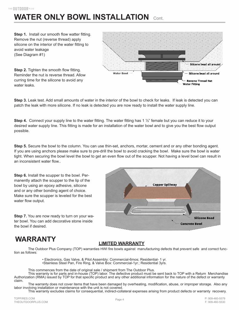
Burner Ring
SS Nipple
LP Orifice(LP Applications ONLY)
Mounting Brasket
Gas Line
Fire Pan
Component Overview
PROPERLY INSTALLED MATCH LIT FIRE BOWL DIAGRAMSNatural Gas Liquid Propane

TOPFIRES.COMTHEOUTDOORPLUS.COM
Page 10 P: 909-460-5579F: 909-460-5530
FIRE ONLY BOWL INSTALLATION Cont.
W A R N I N GDo not use any other material as filler/topping media inside fire features other than those listed below.
Using improper media inside a fire feature could result in damage to property orinjury to persons nearby due to media ‘popping’ or ‘exploding’ due to heat
ACCEPTABLE MEDIA FOR FIRE FEATURES
LIST OF ACCEPTABLE MEDIA FOR FIRE FEATURES
Lava Rock (or other Igneous Rock) NO LARGER THAN 2” in diameterFireglass approved for use in fire featuresManmade stone for use in fire features (Refractory Material)
The use of media inside fire features is recommended due to the fact it enhances the look of the fire feature but also improves its performance by forcing the gas emanating from the burner to mix as it passes through the media. This ‘mix-ing’ of gases creates an even flame throughout the feature and helps spread the flame from the Pilot Burner throughout the burner quicker than when there is no media. Recommended thickness of the media above the burner element is NO MORE than 2”.
INSTALLATION NOTE
INSTALLATION OF MEDIA IN FIRE FEATURES
No more than 1” of media should cover the burner. Adding more may cause damage
There are several options when it comes to topping material for a fire feature; large lava chunks, fire glass and fire stones. In this example we are using 1” lava rock. You will need a layer that is 2” - 3” thick to properly cover the fire feature while at the same time allowing plenty of oxygen to mix with the gas coming from the fire ring. This lava rock is more expensive that the “filler” lava rock but is still fairly inexpensive and readily available in the BBQ section of most hardware stores.

TOPFIRES.COMTHEOUTDOORPLUS.COM
Page 11 P: 909-460-5579F: 909-460-5530
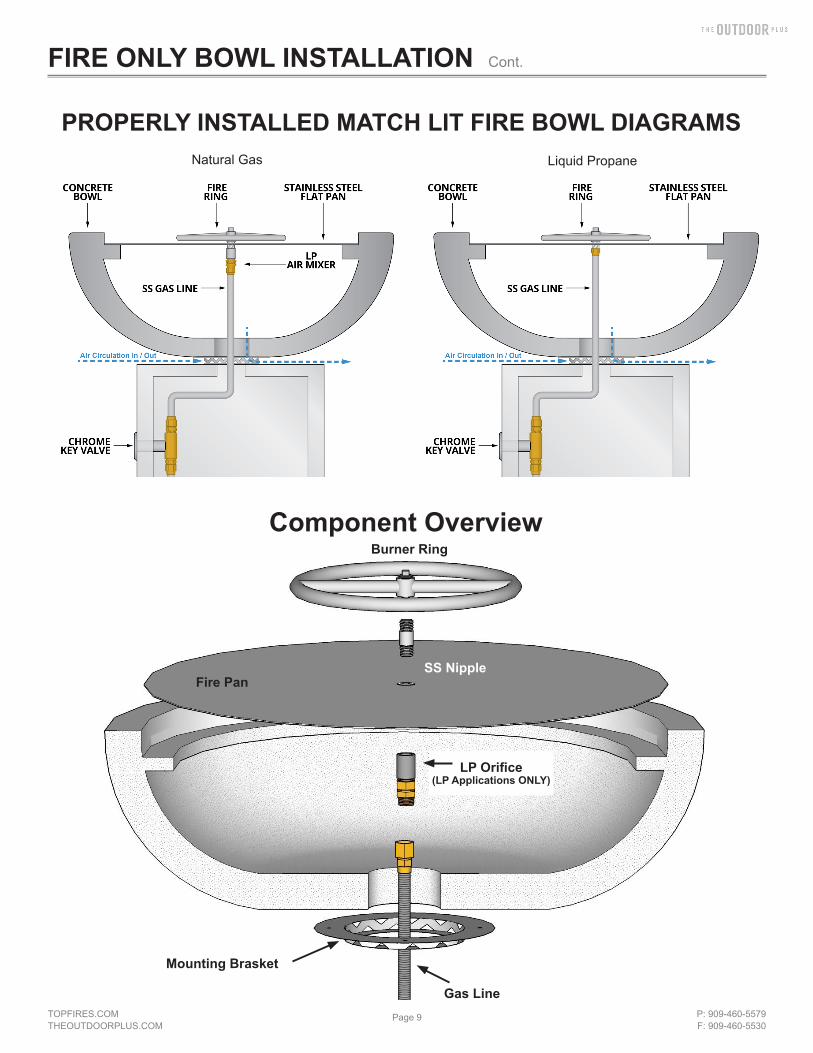
WARNING: before use, be sure to test all gas connection for leaks. Do not use fire bowl if there is any evidence of leaking gas. If leaking gas suspected, turn off the main gas supply and repair immediatelyWARNING: Do not use the fire bowl if any part has been submerged under water. Immediately call a qualified technician to inspect the fire bowlWARNING: never use any Material that is non-porous and holds moisture such as gravel, pebbles, river rocks, etc. This material, when heated, will cause moisture trapped inside to boil and fracture unexpectedly. This material is not sufficiently porous to allow heated steams to readily escape which can break and cause personal injury or damageWARNING: solid fuels shall not be burned in the fire bowl. Leaves, sticks, wood, paper, clothing, food, should be kept away from the fire bowl. Fire bowl is not for cooking. Make sure that there is no vegetation or other objects over the top or sides of the fire bowl that could interfere with safe operation. See the clearance from combustibles diagram at the end of this document.WARNING: if lava rock is wet, allow fire bowl to burn for 45 prior to coming within 15 feet of the fire bowl.Warranty requirement: when not in use, the fire bowl must be covered.Important: initial start-up: it may be necessary to purge Air in the Gas Lines after system installation.
START UP1. Stop! If you smell gas: 1) shut off gas to appliance. 2) Extinguish any open flame. 3) If odor continues, keep away from
appliance and immediately call gas supplier or fire department.2. Ensure fire bowl is clear of people, debris,that all covers are removed and the feature is safe to start.3. Place ling handles lighter or match while burning on top of th fire bowl4. Slowly turn “on” the gas valve.5. After burner lights, remove the lighter or match6. Adjust flame to desired height7. If burner does not light, turn valve to “off” position and allow gas to clear then repeat steps 3-78. Never alter the design of the fire bowl9. Ensure firepit, children and patrons are supervised by a responsible adult that is familiar with emergency shut down.10. Flammable materials should not be places on or near the fire bowl11. This product is not for use with small tanks. It is intended to be connected to fixed piping system only.
WARNING: Any guard or protective device removed for servicing must be replaced prior to operating the fire bowl.WARNING: Installation and repair should be done by a qualified service person. Fire bowls should be inspected prior to use and at least annually by a qualified service person.WARNING: Ensure gas and power (if applicable) are shut off and fire bowl is cool before servicing• Keep fire bowl covered at all times when not in use.• In some areas of the country spiders or insects have been known to build nest and or lay eggs in the venture holes
of the air-mixer for LP units. This can cause fuel to fill the fire feature cavity and result in personal injury or property damage. Periodical inspection by a qualified service technician of the air-intake is required to ensure your fire feature performs properly.
• Keep any debris out of fire bowl- clean as needed.• Ring Cleaning: (1 x YR) If flames exhibit any abnormal shapes or behavior, or if burner fails to ignite properly, then the
burner holes may require cleaning. The appliance can be cleaned by carefully removing the media to allow access to burner. Use a brush to carefully remove dust, spider webs, and loose particles from base, logs, and fire ring itself. If evidence of damage, fire ring must be replaced with fire ring specified by manufacturer
FIRE BOWL OPERATION
MAINTENANCE
FIRE ONLY BOWL INSTALLATION Cont.

TOPFIRES.COMTHEOUTDOORPLUS.COM
Page 12 P: 909-460-5579F: 909-460-5530
Below are some potential causes and countermeasures to the symptoms indicated in bold. Please contact your retailer or certified technician for service & repair. Below are some potential causes and countermeasures to the symptoms indicated in bold. If still unable to resolve issue, please contact your retailer or certified technician.
Will Not Light 1. Air in gas line. If new install, may take several attempts to purge air 2. Debris in gas line. Confirm gas line is clear (insulation, dirt, plastic, excessive pipe sealer etc..)3. Gas Pressure Improper Confirm proper gas pressure found
Will Not Stay Lit1. Gas Pressure Improper Confirm proper gas pressure found (Section 1)2. Improperly applied media Review Media in (Section 5) Noise1. Whistling Sound Change Flex line routing.
TROUBLESHOOTING
WARRANTY
FIRE ONLY BOWL INSTALLATION Cont.
LIMITED WARRANTY The Outdoor Plus Company (TOP) warranties HWI fire bowls against manufacturing defects that pre-vent safe and correct function as follows:
• Electronics, Gas Valve, & Pilot Assembly: Commercial-6mos; Residential- 1 yr. •Stainless Steel Pan, Fire Ring, & Valve Box: Commercial-1yr.; Residential 3yrs.
This commences from the date of original sale / shipment from The Outdoor Plus. This warranty is for parts and in-house (TOP) labor. The defective product must be sent back to TOP with a Return Merchandise Authorization (RMA) issued by TOP for that specific product and any other addi-tional information for the nature of the defect or warranty claim. The warranty does not cover items that have been damaged by overheating, modification, abuse, or improper storage. Also any labor involving installation or maintenance with the unit is not covered. This warranty excludes claims for consequential, indirect-collateral expenses arising from product de-fects or warranty recovery.

TOPFIRES.COMTHEOUTDOORPLUS.COM
Page 13 P: 909-460-5579F: 909-460-5530
WARNINGFOR OUTDOOR USE ONLY
FIRE & WATER BOWLMATCH LIT IGNITION
*READ THIS MANUAL BEFORE INSTALLATION OF THE UNIT
WARNING:Improper installation, adjustment, alteration, service, or maintenance can cause injury or property damage. Read the installation, operating, and maintenance instructions thoroughly before installing or servicing this equipment.
WARNING:Do NOT Store or use gasoline or other flammable vapors and liquids in vicinity of this or any other appliance.An LP cylinder not connected for use shall not be stored in the vicinity of this or any other unit.
WARNING:For use with Natural Gas or Liquid Propane ONLY
NO SOLID FUELS TO BE USED
CARBON MONOXIDE HAZARDThis appliance can produce carbon monoxide which has no odor.Using it in an enclosed space can kill you.Never use this appliance in an enclosed space such as a camper, tent car or home.
We suggest that our products be serviced by a professional certified in the U.S. By the National Fireplace Institute as a NFI Specialists
Installation: we suggest that our products be installed by professionals that are locally licensed by the authority having jurisdiction in gas piping
Installation must conform with local codes or, in the absence of local codes, with theNational Fuel Gas Code, ANSI Z223.1 / NFPA 54, or International Fuel Gas Code.The appliance, when installed, must be electrically grounded in accordance with local codes or, inthe absence of local codes, with the National Electric Code, ANSI/NFPA 70, if applicable.
TAMPERING, MANIPULATING, AND/OR ALTERATIONS TO THE UNIT WILL VOID THE WARRANTY IMMEDIATELY

TOPFIRES.COMTHEOUTDOORPLUS.COM
Page 14 P: 909-460-5579F: 909-460-5530
Please carefully follow the instructions in this manual to prevent personal injury or property loss. Instructions are updated as needed. It is the installer’s responsibility to periodically review instruction for applicable updates.
The steps listed asWARNING: Contains information critical to the safe installation and operation of the fire bowl.WARRANTY REQUIREMENT: Must be strictly followed to qualify for product warranty.Warranty will be void if not followed.IMPORTANT: Are notes and insights to help ensure product satisfaction and serviceability.WARNING: It is the installer’s responsibility to ensure a safe installation and to educate the end user as to properoperation. Leave this manual with the end user.WARNING: Never alter product or configuration in any way.WARNING: We suggest that our products be installed by professionals that are locally licensed by the authority having jurisdiction in gas piping. We suggest that our products be serviced annually by a professional certified in the US by theNational Fireplace Institute (NFI) as NFI Gas Specialists or in Canada by WETT (Wood Energy Technical Training).Installer must follow all instructions carefully to ensure proper performance and safety.The Outdoor Plus Company is not responsible for your actions.WARNING: Product is not intended to be a starter for wood or any other combustibles.WARNING: Product is not for use with small LP Tanks and must utilize permanent fixed piping for fuel supply.WARNING: It is the responsibility of the installer to follow:• The National Fuel Gas Code, ANSI Z223.1/NFPA 54 or International Fuel Gas Code.• The National Electrical Code, ANSI/NFPA 70.• Local Codes
WARNING: Verify correct gas/fuel type and pressure. Never use an alternative fuel to include bio-fuel, ethanol, lighter fluid or any other fuel. Gas pressure and type should be checked prior to use and installation. Natural Gas Fire bowl: Supply Pressure: Minimum: 3.5” W.C.; Maximum: 7.0” W.C. LP Gas: Supply Pressure: Minimum: 8.0” W.C.; Maximum: 11.0” W.C.
FIRE & WATER BOWL INSTALLATION Cont.
General Information
Selecting the LocationWARNING: All fire bowls, match lit kits, and spark ignition systems are designed and intended for outdoor use only.WARNING: All fire bowls must have a gas shutoff on the outside of the exterior of the fire bowl to allow for emergency shut off and maintenance.WARNING: Select a location where the fire bowl can be attended during operation. Never leave an operating fire bowl unat-tended or by someone not familiar with its operation or emergency shut off locations.WARNING: Both children and adults should be alerted to the hazards of high surface temperatures and should stay away to avoid burns and clothing ignition.WARNING: Young children should be carefully supervised when they are in the area of fire bowl.WARNING: Clothing or other flammable materials should not be placed on or near fire bowl.WARNING: Fire bowls create very high temperatures - Combustibles must be located far enough away that there is no risk of ignition. (See Clearance From Combustibles diagram at the end of this document)
Fire bowl Clearances from Combustibles (Diagram can be found at the end of this document) Sides Surrounding Fire bowl - 48” From Structure or Combustibles Overhead Clearance - 96” from combustibles overhead
IMPORTANT: It is recommended that material such as granite, marble or other dense stone be kept away from heat and especially flame due to risk of cracking. Manufacturer is not responsible for damage.
TIPS FOR CHOOSING LOCATION• Select a location with good drainage.• Choose a location that allows easy access for installation and maintenance of the fire bowl.• Pick a location that allows sufficient horizontal room to enjoy the fire bowl while allowing a safe distance from the heat and flame.

TOPFIRES.COMTHEOUTDOORPLUS.COM
Page 15 P: 909-460-5579F: 909-460-5530
FIRE & WATER BOWL INSTALLATION Cont.
KEY VALVE HIGHLY RECOMMENDED TO ADJUST HEIGHT OF FLAME OF EACH INDIVIDUAL FIRE FEATURE*KEY VALVE SOLD SEPARATELY
RUNNING GAS LINES• The gas piping shall be installed underground between to each fire bowl. The piping shall be reduced to 1/2” NPT at
each bowl.• To eliminate unnecessary pressure drop, ensure the pipe length and amount of elbows used is minimized. Yellow
corrugated flex lines should not be used.• Gas lines should be centered in the middle of the column.
• Secure mounting bracket to mounting location with anchors rated for material being affixed. (Anchors not supplied by The Outdoor Plus.)
• Avoid grout seams when installing anchors• Center cutout hole must be no larger than 4” inches square or diameter. Any larger and the mounting bracket will not
have enough area to be properly secured. • Use bracket to locate and mark the hole location.• Do NOT kink or sharply bend any of the stainless steel gas lines. • Do NOT use yellow corrugated gas lines.• Key Valves near the bowl are recommended for flame adjustment.
MOUNTING ON PILLAR/WALL

TOPFIRES.COMTHEOUTDOORPLUS.COM
Page 16 P: 909-460-5579F: 909-460-5530
FIRE & WATER BOWL INSTALLATION Cont.
Water flow requirements: 12-15 gpmScupper will have a ¾” male fitting
1. Install a ¾” water supply line capable of 12-15 GPM as shown in diagram2. The scupper will have a ¾” male fitting3. You can reduce to ½” but this might reduce performance of the water flow4. Connect your water line to scupper. You may need to use silicone.5. Make sure all connections are tight and free of leaks6. To firmly attach the scupper, apply a discreet amount of silicone or epoxy adhesive to
the notch in the bowl7. You are now ready to turn on the water portion of the fire and water bowl
INSTALLATIONS OF SCUPPER
WATER LINE SCUPPER
3/4” MALE FITTING

TOPFIRES.COMTHEOUTDOORPLUS.COM
Page 17 P: 909-460-5579F: 909-460-5530
Burner Ring
SS Nipple
Water Line
LP Orifice(LP Applications ONLY)
Gas Line
Mounting Bracket
Water Line
Copper Scupper
Fire Pan• Notch for Scupper
COMPONENT OVERVIEW
FIRE & WATER BOWL INSTALLATION Cont.

TOPFIRES.COMTHEOUTDOORPLUS.COM
Page 18 P: 909-460-5579F: 909-460-5530
W A R N I N GDo not use any other material as filler/topping media inside fire features other than those listed below.
Using improper media inside a fire feature could result in damage to property orinjury to persons nearby due to media ‘popping’ or ‘exploding’ due to heat
ACCEPTABLE MEDIA FOR FIRE FEATURES
LIST OF ACCEPTABLE MEDIA FOR FIRE FEATURES
Lava Rock (or other Igneous Rock) NO LARGER THAN 2” in diameterFireglass approved for use in fire featuresManmade stone for use in fire features (Refractory Material)
The use of media inside fire features is recommended due to the fact it enhances the look of the fire feature but also improves its performance by forcing the gas emanating from the burner to mix as it passes through the media. This ‘mix-ing’ of gases creates an even flame throughout the feature and helps spread the flame from the Pilot Burner throughout the burner quicker than when there is no media. Recommended thickness of the media above the burner element is NO MORE than 2”. Due to the fact the Pilot Burner must be partially exposed to oxygen in order to ignite the pilot flame during startup DO NOT COMPLETELY COVER THE PILOT BURNER. When installation of the media is complete the top of the Pilot Burner Protective Cover should be visible.
INSTALLATION NOTE
Do NOT cover the top of the pilot.Keep the top exposed
No more than 1” of media should cover the burner. Adding more may cause damage
FIRE & WATER BOWL INSTALLATION Cont.
INSTALLATION OF MEDIA IN FIRE FEATURES
No more than 1” of media should cover the burner. Adding more may cause damage
There are several options when it comes to topping material for a fire feature; large lava chunks, fire glass and fire stones. In this example we are using 1” lava rock. You will need a layer that is 2” - 3” thick to properly cover the fire feature while at the same time allowing plenty of oxygen to mix with the gas coming from the fire ring. This lava rock is more expensive that the “filler” lava rock but is still fairly inexpensive and readily available in the BBQ section of most hardware stores.
TOPFIRES.COMTHEOUTDOORPLUS.COM
Page 19 P: 909-460-5579F: 909-460-5530
FIRE & WATER BOWL INSTALLATION Cont.
WARNING: before use, be sure to test all gas connection for leaks. Do not use fire bowl if there is any evidence of leaking gas. If leaking gas suspected, turn off the main gas supply and repair immediatelyWARNING: Do not use the fire bowl if any part has been submerged under water. Immediately call a qualified technician to inspect the fire bowlWARNING: never use any Material that is non-porous and holds moisture such as gravel, pebbles, river rocks, etc. This material, when heated, will cause moisture trapped inside to boil and fracture unexpectedly. This material is not sufficiently porous to allow heated steams to readily escape which can break and cause personal injury or damageWARNING: solid fuels shall not be burned in the fire bowl. Leaves, sticks, wood, paper, clothing, food, should be kept away from the fire bowl. Fire bowl is not for cooking. Make sure that there is no vegetation or other objects over the top or sides of the fire bowl that could interfere with safe operation. See the clearance from combustibles diagram at the end of this document.WARNING: if lava rock is wet, allow fire bowl to burn for 45 prior to coming within 15 feet of the fire bowl.Warranty requirement: when not in use, the fire bowl must be covered.Important: initial start-up: it may be necessary to purge Air in the Gas Lines after system installation.
START UP1. Stop! If you smell gas: 1) shut off gas to appliance. 2) Extinguish any open flame. 3) If odor continues, keep away from
appliance and immediately call gas supplier or fire department.2. Ensure fire bowl is clear of people, debris,that all covers are removed and the feature is safe to start.3. Place ling handles lighter or match while burning on top of th fire bowl4. Slowly turn “on” the gas valve.5. After burner lights, remove the lighter or match6. Adjust flame to desired height7. If burner does not light, turn valve to “off” position and allow gas to clear then repeat steps 3-78. Never alter the design of the fire bowl9. Ensure firepit, children and patrons are supervised by a responsible adult that is familiar with emergency shut down.10. Flammable materials should not be places on or near the fire bowl11. This product is not for use with small tanks. It is intended to be connected to fixed piping system only.
WARNING: Any guard or protective device removed for servicing must be replaced prior to operating the fire bowl.WARNING: Installation and repair should be done by a qualified service person. Fire bowls should be inspected prior to use and at least annually by a qualified service person.WARNING: Ensure gas and power (if applicable) are shut off and fire bowl is cool before servicing• Keep fire bowl covered at all times when not in use.• In some areas of the country spiders or insects have been known to build nest and or lay eggs in the venture holes
of the air-mixer for LP units. This can cause fuel to fill the fire feature cavity and result in personal injury or property damage. Periodical inspection by a qualified service technician of the air-intake is required to ensure your fire feature performs properly.
• Keep any debris out of fire bowl- clean as needed.• Ring Cleaning: (1 x YR) If flames exhibit any abnormal shapes or behavior, or if burner fails to ignite properly, then the
burner holes may require cleaning. The appliance can be cleaned by carefully removing the media to allow access to burner. Use a brush to carefully remove dust, spider webs, and loose particles from base, logs, and fire ring itself. If evidence of damage, fire ring must be replaced with fire ring specified by manufacturer
FIRE BOWL OPERATION
MAINTENANCE

TOPFIRES.COMTHEOUTDOORPLUS.COM
Page 20 P: 909-460-5579F: 909-460-5530
FIRE & WATER BOWL INSTALLATION Cont.
Below are some potential causes and countermeasures to the symptoms indicated in bold. Please contact your retailer or certified technician for service & repair. Below are some potential causes and countermeasures to the symptoms indicated in bold. If still unable to resolve issue, please contact your retailer or certified technician.
Will Not Light 1. Air in gas line. If new install, may take several attempts to purge air 2. Debris in gas line. Confirm gas line is clear (insulation, dirt, plastic, excessive pipe sealer etc..)3. Gas Pressure Improper Confirm proper gas pressure found
Will Not Stay Lit1. Gas Pressure Improper Confirm proper gas pressure found (Section 1)2. Improperly applied media Review Media in (Section 5) Noise1. Whistling Sound Change Flex line routing.
TROUBLESHOOTING

TOPFIRES.COMTHEOUTDOORPLUS.COM
Page 21 P: 909-460-5579F: 909-460-5530
WARNINGFOR OUTDOOR USE ONLY
FIRE ONLY BOWL - ELECTRONIC *READ THIS MANUAL BEFORE INSTALLATION OF THE UNIT
WARNING:Improper installation, adjustment, alteration, service, or maintenance can cause injury or property damage. Read the installation, operating, and maintenance instructions thoroughly before installing or servicing this equipment.
WARNING:Do NOT Store or use gasoline or other flammable vapors and liquids in vicinity of this or any other appliance.An LP cylinder not connected for use shall not be stored in the vicinity of this or any other unit.
WARNING:For use with Natural Gas or Liquid Propane ONLY
NO SOLID FUELS TO BE USED
CARBON MONOXIDE HAZARDThis appliance can produce carbon monoxide which has no odor.Using it in an enclosed space can kill you.Never use this appliance in an enclosed space such as a camper, tent car or home.
We suggest that our products be serviced by a professional certified in the U.S. By the National Fireplace Institute as a NFI Specialists
Installation: we suggest that our products be installed by professionals that are locally licensed by the authority having jurisdiction in gas piping
Installation must conform with local codes or, in the absence of local codes, with theNational Fuel Gas Code, ANSI Z223.1 / NFPA 54, or International Fuel Gas Code.The appliance, when installed, must be electrically grounded in accordance with local codes or, inthe absence of local codes, with the National Electric Code, ANSI/NFPA 70, if applicable.
TAMPERING, MANIPULATING, AND/OR ALTERATIONS TO THE UNIT WILL VOID THE WARRANTY IMMEDIATELY

TOPFIRES.COMTHEOUTDOORPLUS.COM
Page 22 P: 909-460-5579F: 909-460-5530
Please carefully follow the instructions in this manual to prevent personal injury or property loss. Instructions are updated as needed. It is the installer’s responsibility to periodically review instruction for applicable updates.
The steps listed asWARNING: Contains information critical to the safe installation and operation of the fire bowl.WARRANTY REQUIREMENT: Must be strictly followed to qualify for product warranty.Warranty will be void if not followed.IMPORTANT: Are notes and insights to help ensure product satisfaction and serviceability.WARNING: It is the installer’s responsibility to ensure a safe installation and to educate the end user as to properoperation. Leave this manual with the end user.WARNING: Never alter product or configuration in any way.WARNING: We suggest that our products be installed by professionals that are locally licensed by the authority having jurisdiction in gas piping. We suggest that our products be serviced annually by a professional certified in the US by theNational Fireplace Institute (NFI) as NFI Gas Specialists or in Canada by WETT (Wood Energy Technical Training).Installer must follow all instructions carefully to ensure proper performance and safety.The Outdoor Plus Company is not responsible for your actions.WARNING: Product is not intended to be a starter for wood or any other combustibles.WARNING: Product is not for use with small LP Tanks and must utilize permanent fixed piping for fuel supply.WARNING: It is the responsibility of the installer to follow:• The National Fuel Gas Code, ANSI Z223.1/NFPA 54 or International Fuel Gas Code.• The National Electrical Code, ANSI/NFPA 70.• Local Codes
WARNING: Verify correct gas/fuel type and pressure. Never use an alternative fuel to include bio-fuel, ethanol, lighter fluid or any other fuel. Gas pressure and type should be checked prior to use and installation. Natural Gas Fire bowl: Supply Pressure: Minimum: 3.5” W.C.; Maximum: 7.0” W.C. LP Gas: Supply Pressure: Minimum: 8.0” W.C.; Maximum: 11.0” W.C.
FIRE BOWL WITH ELECTRONIC IGNITION FIRE BOWL
General Information
Selecting the LocationWARNING: All fire bowls, match lit kits, and spark ignition systems are designed and intended for outdoor use only.WARNING: All fire bowls must have a gas shutoff on the outside of the exterior of the fire bowl to allow for emergency shut off and maintenance.WARNING: Select a location where the fire bowl can be attended during operation. Never leave an operating fire bowl unat-tended or by someone not familiar with its operation or emergency shut off locations.WARNING: Both children and adults should be alerted to the hazards of high surface temperatures and should stay away to avoid burns and clothing ignition.WARNING: Young children should be carefully supervised when they are in the area of fire bowl.WARNING: Clothing or other flammable materials should not be placed on or near fire bowl.WARNING: Fire bowls create very high temperatures - Combustibles must be located far enough away that there is no risk of ignition. (See Clearance From Combustibles diagram at the end of this document)
Fire bowl Clearances from Combustibles (Diagram can be found at the end of this document) Sides Surrounding Fire bowl - 48” From Structure or Combustibles Overhead Clearance - 96” from combustibles overhead
IMPORTANT: It is recommended that material such as granite, marble or other dense stone be kept away from heat and especially flame due to risk of cracking. Manufacturer is not responsible for damage.
TIPS FOR CHOOSING LOCATION• Select a location with good drainage.• Choose a location that allows easy access for installation and maintenance of the fire bowl.• Pick a location that allows sufficient horizontal room to enjoy the fire bowl while allowing a safe distance from the heat and flame.
TOPFIRES.COMTHEOUTDOORPLUS.COM
Page 23 P: 909-460-5579F: 909-460-5530
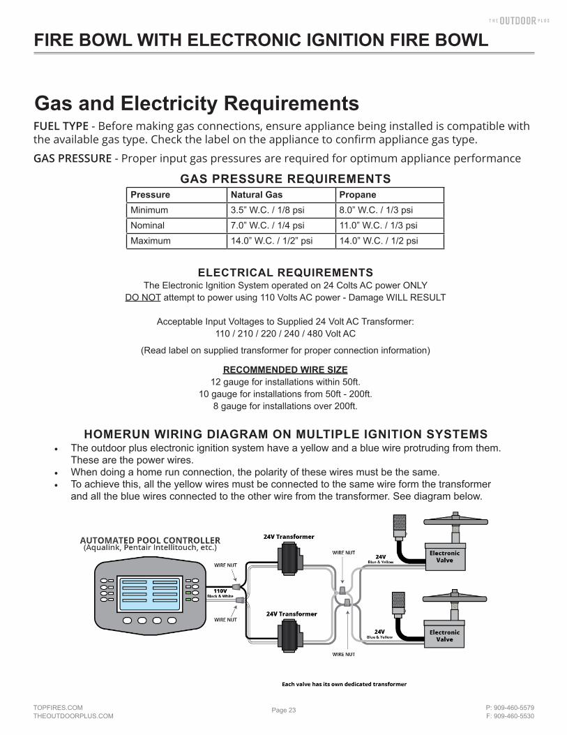
Pressure Natural Gas PropaneMinimum 3.5” W.C. / 1/8 psi 8.0” W.C. / 1/3 psiNominal 7.0” W.C. / 1/4 psi 11.0” W.C. / 1/3 psiMaximum 14.0” W.C. / 1/2” psi 14.0” W.C. / 1/2 psi
ELECTRICAL REQUIREMENTSThe Electronic Ignition System operated on 24 Colts AC power ONLY
DO NOT attempt to power using 110 Volts AC power - Damage WILL RESULT
Acceptable Input Voltages to Supplied 24 Volt AC Transformer:110 / 210 / 220 / 240 / 480 Volt AC
(Read label on supplied transformer for proper connection information)
RECOMMENDED WIRE SIZE12 gauge for installations within 50ft.
10 gauge for installations from 50ft - 200ft.8 gauge for installations over 200ft.
HOMERUN WIRING DIAGRAM ON MULTIPLE IGNITION SYSTEMS• The outdoor plus electronic ignition system have a yellow and a blue wire protruding from them.
These are the power wires.• When doing a home run connection, the polarity of these wires must be the same.• To achieve this, all the yellow wires must be connected to the same wire form the transformer
and all the blue wires connected to the other wire from the transformer. See diagram below.
FUEL TYPE - Before making gas connections, ensure appliance being installed is compatible with the available gas type. Check the label on the appliance to confirm appliance gas type.
GAS PRESSURE - Proper input gas pressures are required for optimum appliance performance
GAS PRESSURE REQUIREMENTS
Gas and Electricity Requirements
FIRE BOWL WITH ELECTRONIC IGNITION FIRE BOWL

TOPFIRES.COMTHEOUTDOORPLUS.COM
Page 24 P: 909-460-5579F: 909-460-5530
KEY VALVE HIGHLY RECOMMENDED TO ADJUST HEIGHT OF FLAME OF EACH INDIVIDUAL FIRE FEATURE*KEY VALVE SOLD SEPARATELY
RUNNING GAS LINES
FIRE BOWL WITH ELECTRONIC IGNITION
• The gas piping shall be installed underground between to each fire bowl. The piping shall be reduced to 1/2” NPT at each bowl.
• To eliminate unnecessary pressure drop, ensure the pipe length and amount of elbows used is minimized. Yellow corrugated flex lines should not be used.
• Gas lines should be centered in the middle of the column.
Electronic Timers & Emergency Stop Switches• When using Dial Timers and Emergency Stop Switches from The Outdoor Plus, ensure they are being
installed between your 110V source and the transformer.• Place the Emergency Stop closest to the 110V source.• The Electronic Timer runs on 110V ONLY. • The Emergency Stop

TOPFIRES.COMTHEOUTDOORPLUS.COM
Page 25 P: 909-460-5579F: 909-460-5530
KEY VALVE HIGHLY RECOMMENDED TO ADJUST HEIGHT OF FLAME OF EACH INDIVIDUAL FIRE FEATURE*KEY VALVE SOLD SEPARATELY
• Secure mounting bracket to mounting location with anchors rated for material being affixed. (Anchors not supplied by The Outdoor Plus.)
• Avoid grout seams when installing anchors• Center cutout hole must be no larger than 4” inches square or diameter. Any larger and the mounting bracket will not
have enough area to be properly secured. • Use bracket to locate and mark the hole location.• Do NOT kink or sharply bend any of the stainless steel gas lines. • Do NOT use yellow corrugated gas lines.• Key Valves near the bowl are recommended for flame adjustment.
MOUNTING ON PILLAR/WALL
FIRE BOWL WITH ELECTRONIC IGNITION FIRE BOWL
TOPFIRES.COMTHEOUTDOORPLUS.COM
Page 26 P: 909-460-5579F: 909-460-5530
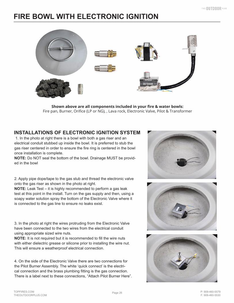
INSTALLATIONS OF ELECTRONIC IGNITION SYSTEM 1. In the photo at right there is a bowl with both a gas riser and an electrical conduit stubbed up inside the bowl. It is preferred to stub the gas riser centered in order to ensure the fire ring is centered in the bowl once installation is complete.NOTE: Do NOT seal the bottom of the bowl. Drainage MUST be provid-ed in the bowl
2. Apply pipe dope/tape to the gas stub and thread the electronic valve onto the gas riser as shown in the photo at right.NOTE: Leak Test – it is highly recommended to perform a gas leak test at this point in the install. Turn on the gas supply and then, using a soapy water solution spray the bottom of the Electronic Valve where it is connected to the gas line to ensure no leaks exist.
3. In the photo at right the wires protruding from the Electronic Valve have been connected to the two wires from the electrical conduit using appropriate sized wire nuts.NOTE: It is not required but it is recommended to fill the wire nuts with either dielectric grease or silicone prior to installing the wire nut. This will ensure a weatherproof electrical connection.
4. On the side of the Electronic Valve there are two connections for the Pilot Burner Assembly. The white ‘quick connect’ is the electri-cal connection and the brass plumbing fitting is the gas connection. There is a label next to these connections, “Attach Pilot Burner Here”.
FIRE BOWL WITH ELECTRONIC IGNITION
Shown above are all components included in your fire & water bowls:Fire pan, Burner, Orifice (LP or NG), , Lava rock, Electronic Valve, Pilot & Transformer

TOPFIRES.COMTHEOUTDOORPLUS.COM
Page 27 P: 909-460-5579F: 909-460-5530
5. The photo at right shows the Electronic Valve after the Pilot Burner Assembly has been connected.NOTE: The electrical connection for the Pilot Burner is a shaped connection thereby ensuring it can only be connected the correct way.Do not forcefully insert into the connection.On the Pilot Burner Assembly side of the connection there is a locking clip on the quick connect that will ‘lock’ the connection in place.Therefore after making the connection lightly tug on the connection to ensure it is in fact ‘locked’ in place.
6A. When installing the fire ring for natural gas applications, select a pipe nipple that is long enough to raise the fire ring Level with the top of the bowl as shown in the photo. Apply pipe dope to both ends of the pipe nipple
6B. When installing the fire ring for propane applications, a brass “Air Mixer” will be installed between the systems and the fire ring as shown to the right.Apply pipe dope to both ends of the Air Mixer and install, along with a coupling. This will create a space between the burner and the air mixer that prevents backfire. NOTE: Air mixer MUST be installed such that the holes are facing down.
7. Lower the stainless steel pan and insert the nipple through thecenter hole. Install the stainless steel fire ring with the holes facing UP.WARNING: If holes are facing down, the electronic valve will overheat, will malfunction, and will need to be replaced.
NG Orifce
6A
LP Orifce
6B
FIRE BOWL WITH ELECTRONIC IGNITION

TOPFIRES.COMTHEOUTDOORPLUS.COM
Page 28 P: 909-460-5579F: 909-460-5530
W A R N I N GDo not use any other material as filler/topping media inside fire features other than those listed below.
Using improper media inside a fire feature could result in damage to property orinjury to persons nearby due to media ‘popping’ or ‘exploding’ due to heat
ACCEPTABLE MEDIA FOR FIRE FEATURES
LIST OF ACCEPTABLE MEDIA FOR FIRE FEATURES
Lava Rock (or other Igneous Rock) NO LARGER THAN 2” in diameterFireglass approved for use in fire featuresManmade stone for use in fire features (Refractory Material)
The use of media inside fire features is recommended due to the fact it enhances the look of the fire feature but also improves its performance by forcing the gas emanating from the burner to mix as it passes through the media. This ‘mix-ing’ of gases creates an even flame throughout the feature and helps spread the flame from the Pilot Burner throughout the burner quicker than when there is no media. Recommended thickness of the media above the burner element is NO MORE than 2”. Due to the fact the Pilot Burner must be partially exposed to oxygen in order to ignite the pilot flame during startup DO NOT COMPLETELY COVER THE PILOT BURNER. When installation of the media is complete the top of the Pilot Burner Protective Cover should be visible.
INSTALLATION NOTE
INSTALLATION OF MEDIA IN FIRE FEATURES
Do NOT cover the top of the pilot.Keep the top exposed
No more than 1” of media should cover the burner. Adding more may cause damage
There are several options when it comes to topping material for a fire feature; large lava chunks, fire glass and fire stones. In this example we are using 1” lava rock. You will need a layer that is 2” - 3” thick to properly cover the fire feature while at the same time allowing plenty of oxygen to mix with the gas coming from the fire ring. This lava rock is more expensive that the “filler” lava rock but is still fairly inexpensive and readily available in the BBQ section of most hardware stores.
NOTE: The top of the pilot burner is level with the top of the burning media. The system will not work properly if the pilot is positioned higher than the burner ring
FIRE BOWL WITH ELECTRONIC IGNITION

TOPFIRES.COMTHEOUTDOORPLUS.COM
Page 29 P: 909-460-5579F: 909-460-5530
WARNING: before use, be sure to test all gas connection for leaks. Do not use fire bowl if there is any evidence of leaking gas. If leaking gas suspected, turn off the main gas supply and repair immediatelyWARNING: Do not use the fire bowl if any part has been submerged under water. Immediately call a qualified technician to inspect the fire bowlWARNING: never use any Material that is non-porous and holds moisture such as gravel, pebbles, river rocks, etc. This material, when heated, will cause moisture trapped inside to boil and fracture unexpectedly. This material is not sufficiently porous to allow heated steams to readily escape which can break and cause personal injury or damageWARNING: solid fuels shall not be burned in the fire bowl. Leaves, sticks, wood, paper, clothing, food, should be kept away from the fire bowl. Fire bowl is not for cooking. Make sure that there is no vegetation or other objects over the top or sides of the fire bowl that could interfere with safe operation. See the clearance from combustibles diagram at the end of this document.WARNING: if lava rock is wet, allow fire bowl to burn for 45 prior to coming within 15 feet of the fire bowl.Warranty requirement: when not in use, the fire bowl must be covered.Important: initial start-up: it may be necessary to purge Air in the Gas Lines after system installation.
START UP1. Stop! If you smell gas: 1) shut off gas to appliance. 2) Extinguish any open flame. 3) If odor continues, keep away from
appliance and immediately call gas supplier or fire department.2. Ensure fire bowl is clear of people, debris,that all covers are removed and the feature is safe to start.3. Place ling handles lighter or match while burning on top of th fire bowl4. Slowly turn “on” the gas valve.5. After burner lights, remove the lighter or match6. Adjust flame to desired height7. If burner does not light, turn valve to “off” position and allow gas to clear then repeat steps 3-78. Never alter the design of the fire bowl9. Ensure firepit, children and patrons are supervised by a responsible adult that is familiar with emergency shut down.10. Flammable materials should not be places on or near the fire bowl11. This product is not for use with small tanks. It is intended to be connected to fixed piping system only.
WARNING: Any guard or protective device removed for servicing must be replaced prior to operating the fire bowl.WARNING: Installation and repair should be done by a qualified service person. Fire bowls should be inspected prior to use and at least annually by a qualified service person.WARNING: Ensure gas and power (if applicable) are shut off and fire bowl is cool before servicing• Keep fire bowl covered at all times when not in use.• In some areas of the country spiders or insects have been known to build nest and or lay eggs in the venture holes
of the air-mixer for LP units. This can cause fuel to fill the fire feature cavity and result in personal injury or property damage. Periodical inspection by a qualified service technician of the air-intake is required to ensure your fire feature performs properly.
• Keep any debris out of fire bowl- clean as needed.• Ring Cleaning: (1 x YR) If flames exhibit any abnormal shapes or behavior, or if burner fails to ignite properly, then the
burner holes may require cleaning. The appliance can be cleaned by carefully removing the media to allow access to burner. Use a brush to carefully remove dust, spider webs, and loose particles from base, logs, and fire ring itself. If evidence of damage, fire ring must be replaced with fire ring specified by manufacturer
FIRE BOWL OPERATION
MAINTENANCE
FIRE BOWL WITH ELECTRONIC IGNITION

TOPFIRES.COMTHEOUTDOORPLUS.COM
Page 30 P: 909-460-5579F: 909-460-5530
WARNING: before use, be sure to test all gas connection for leaks. Do not use fire bowl if there is any evidence of leaking gas. If leaking gas suspected, turn off the main gas supply and repair immediatelyWARNING: Do not use the fire bowl if any part has been submerged under water. Immediately call a qualified technician to inspect the fire bowlWARNING: never use any Material that is non-porous and holds moisture such as gravel, pebbles, river rocks, etc. This material, when heated, will cause moisture trapped inside to boil and fracture unexpectedly. This material is not sufficiently porous to allow heated steams to readily escape which can break and cause personal injury or damageWARNING: solid fuels shall not be burned in the fire bowl. Leaves, sticks, wood, paper, clothing, food, should be kept away from the fire bowl. Fire bowl is not for cooking. Make sure that there is no vegetation or other objects over the top or sides of the fire bowl that could interfere with safe operation. See the clearance from combustibles diagram at the end of this document.WARNING: if lava rock is wet, allow fire bowl to burn for 45 prior to coming within 15 feet of the fire bowl.Warranty requirement: when not in use, the fire bowl must be covered.Important: initial start-up: it may be necessary to purge Air in the Gas Lines after system installation.
FIRE BOWL OPERATION
FIRE FEATURE START UP
FIRE BOWL WITH ELECTRONIC IGNITION
1. Prior to turning appliance on visually inspect fire feature to ensure debris such as leaves or other combustible material has not collected inside the feature which could burn and emit embers once the fire feature is turned on. Also ensure any person standing close to the fire feature is aware you will be turning the fire feature on prior to actually turning it on.2. Turn fire feature on by turning on the electrical device used to power the fire feature.
Sequence of Operation during Ignition1. Power is applied2. Hot Surface Igniter (Glow Plug) becomes hot and 4 seconds later the Pilot Gas Valve opens3. Within 10 seconds of power application Pilot Flame should be visible (at night only)4. Within 10 seconds of Pilot Flame Ignition burner (fire ring/burner bar) should ignite
FIRE FEATURE SHUTDOWN1. Turn fire feature off by turning off the electrical device used to initially power the fire feature
WARNINGIf fire feature fails to turn off completely (small flames still visible)
Turn off gas supply using the manual gas shutoff.
WARNING: Maintenance should be done by a qualified service technician. The appliance should be inspected before use and at least annually by a qualified service technician.WARNING: Ensure gas and power are shut off and appliance is cool before servicing.WARNING: Any guard or protective device removed for servicing must be replaced prior to operation.
Prior to Each Use1. Inspect for debris in Fire Feature – remove debris prior to use
Semi-Annually1. Visually inspect Pilot Burner for debris/insect infestation (spider webs)2. Visually inspect burner holes for debris/insect infestation3. Clean either of the above as necessary using compressed air.
Annually1. Visually inspect Pilot Burner for excess corrosion due to heat and moisture.2. Turn fire feature on to ensure proper operation.
MAINTENANCE

TOPFIRES.COMTHEOUTDOORPLUS.COM
Page 31 P: 909-460-5579F: 909-460-5530
REPLACEMENT PARTS
OPT-PIR - Plot Igniter Assembly OPT-24V - 24 Volts AC Transformer
I installed the Electronic Ignition System, turned it on and nothing happened
When this occurs it is usually due to an electrical wiring / power issue. Check all your electrical connections thoroughly to ensure all wires at the transformer and inside the fire feature are connected properly. If it appears all wiring is con-nected properly, disconnect the wires at the fire feature, attach a Multimeter to the wires to confirm a minimum of 12 volts when the fire feature is turned on. If you determine that you do not have a minimum of 12 volts at the fire feature conduct the same test at the transformer to ensure the transformer is in fact producing a minimum of 12 volts. If you do have a minimum of 12 volts at the fire feature contact us for further assistance.
I installed the Electronic Ignition System, turned it on and I can see the glow plug glowing orange and I can hear gas flowing but it will not ignite.
There are two possible causes to this problem; Air in the Gas Line or not enough Electrical Current to the fire feature.
Air in the Gas Line. If a new gas line was installed and the air was never purged from it prior to installing the Elec-tronic Ignition System then it may take several times of turning the fire feature on and off before the air is purged from the gas line. Here is how our system works; after you turn it on the glow plug will come on first followed by the Pilot Gas Valve opening 4 seconds later. For the next 180 seconds (3 minutes) the glow plug will cycle on and off every 30 seconds while the Pilot Gas Valve will remain on the entire time. Therefore if you are attempting to purge air from the gas line, turn the system on and leave it on for approximately 3 minutes. Then turn it off and then back on (no need to wait to turn it back on). Let the system run for another 3 minutes. Usually when purging air from a new gas line you will need to cycle the power several times as described above before gas begins to flow. If at any point you smell gas but still don’t have ignition, attempt to light the Pilot flame with a hand-held lighter. If the flame ignites when you light it by hand, go to the section below, “Electrical Current”.
Electrical Current. If you have determined that air in the gas line is not the problem then most likely the failure to ignite is due to the fact the glow plug is not getting hot enough to ignite the gas. The reason a glow plug will not get hot enough is due to the fact it is not getting enough ‘amps’. Often times when troubleshooting electricians will check the electrical power and when they see they have a minimum of 12 volts they think everything is fine electrically so there must be a problem with the Electronic Ignition System. The problem is not due to the volts but rather the amps. The number of amps reaching the fire feature is heavily dependent on the gauge wire used between the transformer and the fire feature. Our Install Instructions require no less than 12 gauge wire be run for all fire features. Often times we learn that in many cases less than 12 gauge wire has been used and herein lies the cause of the problem.Here is how you check to determine if enough Electrical Current (amps) are getting to the fire feature:
1. CAUTION: Turn off the gas supply prior to the next step.2. Using a clamp on ammeter, clamp the ammeter around one of the wires providing power to the ElectronicIgnition System.3. Turn the fire feature on.4. The amps you should see will range between 1.4 to 1.6 amps initially. Four seconds after being turned on the amps will jump to approximately 2.0 amps.
If you do not see the amps listed above AND the wire gauge used was less than 12 gauge wire – change the wiring.Otherwise contact us for further assistance.
I turned the Fire Feature off but I still see small flames emanating from the fire feature.
Turn the fire feature on, let the main fire ring light and then turn it off again – do this several times. Small pieces of debris from the gas line can get caught in the main or pilot valve thereby preventing it from closing all the way. This will sometimes happen with a new gas line. By cycling power you can often times dislodge the debris. If cycling power does not rectify the problem, turn the gas off using the manual gas shutoff and contact us for further assistance.
TROUBLE SHOOTING

TOPFIRES.COMTHEOUTDOORPLUS.COM
Page 32 P: 909-460-5579F: 909-460-5530
WARNINGFOR OUTDOOR USE ONLY
FIRE / FIRE & WATER BOWL WITH ELECTRONIC IGNITION INSTALLATION
*READ THIS MANUAL BEFORE INSTALLATION OF THE UNIT
WARNING:Improper installation, adjustment, alteration, service, or maintenance can cause injury or property damage. Read the installation, operating, and maintenance instructions thoroughly before installing or servicing this equipment.
WARNING:Do NOT Store or use gasoline or other flammable vapors and liquids in vicinity of this or any other appliance.An LP cylinder not connected for use shall not be stored in the vicinity of this or any other unit.
WARNING:For use with Natural Gas or Liquid Propane ONLY
NO SOLID FUELS TO BE USED
CARBON MONOXIDE HAZARDThis appliance can produce carbon monoxide which has no odor.Using it in an enclosed space can kill you.Never use this appliance in an enclosed space such as a camper, tent car or home.
We suggest that our products be serviced by a professional certified in the U.S. By the National Fireplace Institute as a NFI Specialists
Installation: we suggest that our products be installed by professionals that are locally licensed by the authority having jurisdiction in gas piping
Installation must conform with local codes or, in the absence of local codes, with theNational Fuel Gas Code, ANSI Z223.1 / NFPA 54, or International Fuel Gas Code.The appliance, when installed, must be electrically grounded in accordance with local codes or, inthe absence of local codes, with the National Electric Code, ANSI/NFPA 70, if applicable.
TAMPERING, MANIPULATING, AND/OR ALTERATIONS TO THE UNIT WILL VOID THE WARRANTY IMMEDIATELY

TOPFIRES.COMTHEOUTDOORPLUS.COM
Page 33 P: 909-460-5579F: 909-460-5530
Please carefully follow the instructions in this manual to prevent personal injury or property loss. Instructions are updated as needed. It is the installer’s responsibility to periodically review instruction for applicable updates.
The steps listed asWARNING: Contains information critical to the safe installation and operation of the fire bowl.WARRANTY REQUIREMENT: Must be strictly followed to qualify for product warranty.Warranty will be void if not followed.IMPORTANT: Are notes and insights to help ensure product satisfaction and serviceability.WARNING: It is the installer’s responsibility to ensure a safe installation and to educate the end user as to properoperation. Leave this manual with the end user.WARNING: Never alter product or configuration in any way.WARNING: We suggest that our products be installed by professionals that are locally licensed by the authority having jurisdiction in gas piping. We suggest that our products be serviced annually by a professional certified in the US by theNational Fireplace Institute (NFI) as NFI Gas Specialists or in Canada by WETT (Wood Energy Technical Training).Installer must follow all instructions carefully to ensure proper performance and safety.The Outdoor Plus Company is not responsible for your actions.WARNING: Product is not intended to be a starter for wood or any other combustibles.WARNING: Product is not for use with small LP Tanks and must utilize permanent fixed piping for fuel supply.WARNING: It is the responsibility of the installer to follow:
• The National Fuel Gas Code, ANSI Z223.1/NFPA 54 or International Fuel Gas Code.• The National Electrical Code, ANSI/NFPA 70.• Local Codes
WARNING: Verify correct gas/fuel type and pressure. Never use an alternative fuel to include bio-fuel, ethanol, lighter fluid or any other fuel. Gas pressure and type should be checked prior to use and installationSEE NEXT PAGE “GAS PRESSURE REQUIREMENTS”
General Information
Selecting the LocationWARNING: All fire bowls, match lit kits, and spark ignition systems are designed and intended for outdoor use only.WARNING: All fire bowls must have a gas shutoff on the outside of the exterior of the fire bowl to allow for emergency shut off and maintenance.WARNING: Select a location where the fire bowl can be attended during operation. Never leave an operating fire bowlunattended or by someone not familiar with its operation or emergency shut off locations.WARNING: Both children and adults should be alerted to the hazards of high surface temperatures and should stay away to avoid burns and clothing ignition.WARNING: Young children should be carefully supervised when they are in the area of fire bowl.WARNING: Clothing or other flammable materials should not be placed on or near fire bowl.WARNING: Fire bowls create very high temperatures - Combustibles must be located far enough away that there is no risk of ignition. (See Clearance From Combustibles diagram at the end of this document)
Fire bowl Clearances from Combustibles (Diagram can be found at the end of this document) Sides Surrounding Fire bowl - 48” From Structure or Combustibles Overhead Clearance - 96” from combustibles overhead
IMPORTANT: It is recommended that material such as granite, marble or other dense stone be kept away from heat and especially flame due to risk of cracking. Manufacturer is not responsible for damage.
TIPS FOR CHOOSING LOCATION• Select a location with good drainage.• Choose a location that allows easy access for installation and maintenance of the fire bowl.• Pick a location that allows sufficient horizontal room to enjoy the fire bowl while allowing a safe distance from the heat and flame.
FIRE / FIRE & WATER BOWL WITH ELECTRONIC IGNITION

TOPFIRES.COMTHEOUTDOORPLUS.COM
Page 34 P: 909-460-5579F: 909-460-5530
Pressure Natural Gas PropaneMinimum 3.5” W.C. / 1/8 psi 8.0” W.C. / 1/3 psiNominal 7.0” W.C. / 1/4 psi 11.0” W.C. / 1/3 psiMaximum 14.0” W.C. / 1/2” psi 14.0” W.C. / 1/2 psi
ELECTRICAL REQUIREMENTSThe Electronic Ignition System operated on 24 Colts AC power ONLY
DO NOT attempt to power using 110 Volts AC power - Damage WILL RESULT
Acceptable Input Voltages to Supplied 24 Volt AC Transformer:110 / 210 / 220 / 240 / 480 Volt AC
(Read label on supplied transformer for proper connection information)
RECOMMENDED WIRE SIZE12 gauge for installations within 50ft.
10 gauge for installations from 50ft - 200ft.8 gauge for installations over 200ft.
HOMERUN WIRING DIAGRAM ON MULTIPLE IGNITION SYSTEMS• The outdoor plus electronic ignition system have a yellow and a blue wire protruding from them.
These are the power wires.• When doing a home run connection, the polarity of these wires must be the same.• To achieve this, all the yellow wires must be connected to the same wire form the transformer
and all the blue wires connected to the other wire from the transformer. See diagram below.
FUEL TYPE - Before making gas connections, ensure appliance being installed is compatible with the available gas type. Check the label on the appliance to confirm appliance gas type.
GAS PRESSURE - Proper input gas pressures are required for optimum appliance performance
GAS PRESSURE REQUIREMENTS
Gas and Electricity Requirements
FIRE / FIRE & WATER BOWL WITH ELECTRONIC IGNITION

TOPFIRES.COMTHEOUTDOORPLUS.COM
Page 35 P: 909-460-5579F: 909-460-5530
Electronic Timers & Emergency Stop Switches
Gas, Water, Electrical Lines Diagram
• When using Dial Timers and Emergency Stop Switches from The Outdoor Plus, ensure they are being installed be-tween your 110V source and the transformer.
• Place the Emergency Stop closest to the 110V source.• The Electronic Timer runs on 110V ONLY. • The Emergency Stop
• The gas piping shall be installed underground between the control panel and each fire bowl. The piping shall be reduced to 1/2” NPT at each bowl.
• 110V Source into transformer can come from any 110V source, including pool controller or smart home system.• To eliminate unnecessary pressure drop, ensure the pipe length and amount of elbows used is minimized. Yellow
corrugated flex lines should not be used.• Gas, electricity and water lines should be centered in the middle of the column.• In commercial installations, it is recommended to install a key switch and an emergency shut off located within close
proximity and clearly visible sight of the unit.
FIRE / FIRE & WATER BOWL WITH ELECTRONIC IGNITION

TOPFIRES.COMTHEOUTDOORPLUS.COM
Page 36 P: 909-460-5579F: 909-460-5530
KEY VALVE HIGHLY RECOMMENDED TO ADJUST HEIGHT OF FLAME OF EACH INDIVIDUAL FIRE FEATURE*KEY VALVE SOLD SEPARATELY
• Secure mounting bracket to mounting location with anchors rated for material being affixed. (Anchors not supplied by The Outdoor Plus.)
• Avoid grout seams when installing anchors• Center cutout hole must be no larger than 4” inches square or diameter. Any larger and the mounting bracket will not
have enough area to be properly secured. • Use bracket to locate and mark the hole location.• Do NOT kink or sharply bend any of the stainless steel gas lines. • Do NOT use yellow corrugated gas lines.• Key Valves near the bowl are recommended for flame adjustment.
MOUNTING ON PILLAR/WALL
FIRE / FIRE & WATER BOWL WITH ELECTRONIC IGNITION

TOPFIRES.COMTHEOUTDOORPLUS.COM
Page 37 P: 909-460-5579F: 909-460-5530
INSTALLATIONS OF ELECTRONIC IGNITION SYSTEM 1. In the photo at right there is a bowl with both a gas riser and an electrical conduit stubbed up inside the bowl. It is preferred to stub the gas riser centered in order to ensure the fire ring is centered in the bowl once installation is complete.NOTE: Do NOT seal the bottom of the bowl. Drainage MUST be provid-ed in the bowl
2. Apply pipe dope/tape to the gas stub and thread the electronic valve onto the gas riser as shown in the photo at right.NOTE: Leak Test – it is highly recommended to perform a gas leak test at this point in the install. Turn on the gas supply and then, using a soapy water solution spray the bottom of the Electronic Valve where it is connected to the gas line to ensure no leaks exist.
3. In the photo at right the wires protruding from the Electronic Valve have been connected to the two wires from the electrical conduit using appropriate sized wire nuts.NOTE: It is not required but it is recommended to fill the wire nuts with either dielectric grease or silicone prior to installing the wire nut. This will ensure a weatherproof electrical connection.
4. On the side of the Electronic Valve there are two connections for the Pilot Burner Assembly. The white ‘quick connect’ is the electri-cal connection and the brass plumbing fitting is the gas connection. There is a label next to these connections, “Attach Pilot Burner Here”.
FIRE / FIRE & WATER BOWL WITH ELECTRONIC IGNITION
Shown above are all components included in your fire & water bowls:Fire pan, Burner, Orifice (LP or NG), Scupper, Lava rock, Electronic Valve, Pilot & Transformer

TOPFIRES.COMTHEOUTDOORPLUS.COM
Page 38 P: 909-460-5579F: 909-460-5530
5. The photo at right shows the Electronic Valve after the Pilot Burner Assembly has been connected.NOTE: The electrical connection for the Pilot Burner is a shaped connection thereby ensuring it can only be connected the correct way.Do not forcefully insert into the connection.On the Pilot Burner Assembly side of the connection there is a locking clip on the quick connect that will ‘lock’ the connection in place.Therefore after making the connection lightly tug on the connection to ensure it is in fact ‘locked’ in place.
6A. When installing the fire ring for natural gas applications, select a pipe nipple that is long enough to raise the fire ring Level with the top of the bowl as shown in the photo. Apply pipe dope to both ends of the pipe nipple
6B. When installing the fire ring for propane applications, a brass “Air Mixer” will be installed between the systems and the fire ring as shown to the right.Apply pipe dope to both ends of the Air Mixer and install, along with a coupling. This will create a space between the burner and the air mixer that prevents backfire. NOTE: Air mixer MUST be installed such that the holes are facing down.
7. Lower the stainless steel pan and insert the nipple through thecenter hole. Install the stainless steel fire ring with the holes facing UP.WARNING: If holes are facing down, the electronic valve will overheat, will malfunction, and will need to be replaced.
NG Orifce
LP Orifce
FIRE / FIRE & WATER BOWL WITH ELECTRONIC IGNITION
TOPFIRES.COMTHEOUTDOORPLUS.COM
Page 39 P: 909-460-5579F: 909-460-5530
FIRE / FIRE & WATER BOWL WITH ELECTRONIC IGNITION
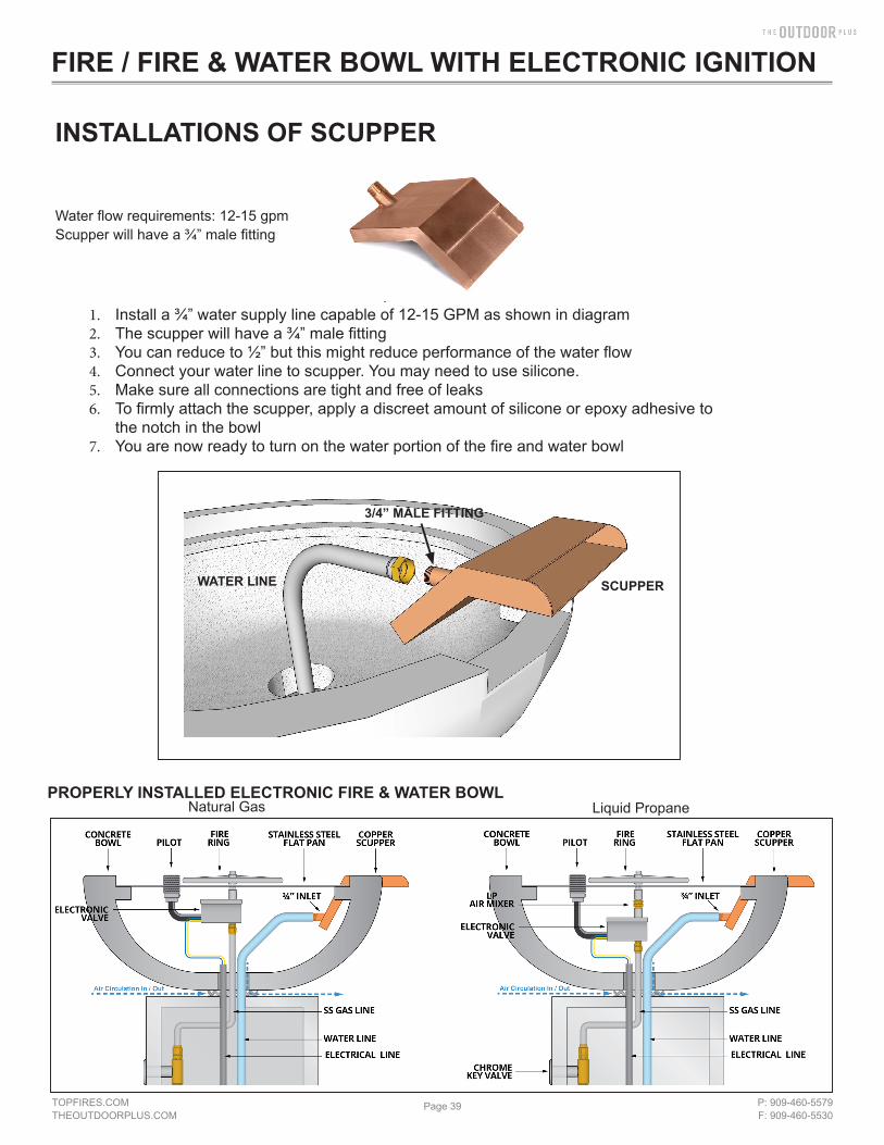
Water flow requirements: 12-15 gpmScupper will have a ¾” male fitting
1. Install a ¾” water supply line capable of 12-15 GPM as shown in diagram2. The scupper will have a ¾” male fitting3. You can reduce to ½” but this might reduce performance of the water flow4. Connect your water line to scupper. You may need to use silicone.5. Make sure all connections are tight and free of leaks6. To firmly attach the scupper, apply a discreet amount of silicone or epoxy adhesive to
the notch in the bowl7. You are now ready to turn on the water portion of the fire and water bowl
INSTALLATIONS OF SCUPPER
WATER LINE SCUPPER
3/4” MALE FITTING
PROPERLY INSTALLED ELECTRONIC FIRE & WATER BOWLNatural Gas Liquid Propane

TOPFIRES.COMTHEOUTDOORPLUS.COM
Page 40 P: 909-460-5579F: 909-460-5530
ElectronicValve
Burner Ring
SS Nipple
Water Line
LP Orifice(LP Applications ONLY)
Conduit
Mounting Brasket
Gas Line
Pilot
Copper Scupper
Fire Pan• Hole for Pilot Igniter• Notch for Scupper
Component Overview
FIRE / FIRE & WATER BOWL WITH ELECTRONIC IGNITION

TOPFIRES.COMTHEOUTDOORPLUS.COM
Page 41 P: 909-460-5579F: 909-460-5530
W A R N I N GDo not use any other material as filler/topping media inside fire features other than those listed below.
Using improper media inside a fire feature could result in damage to property orinjury to persons nearby due to media ‘popping’ or ‘exploding’ due to heat
ACCEPTABLE MEDIA FOR FIRE FEATURES
LIST OF ACCEPTABLE MEDIA FOR FIRE FEATURES
Lava Rock (or other Igneous Rock) NO LARGER THAN 2” in diameterFireglass approved for use in fire featuresManmade stone for use in fire features (Refractory Material)
The use of media inside fire features is recommended due to the fact it enhances the look of the fire feature but also improves its performance by forcing the gas emanating from the burner to mix as it passes through the media. This ‘mix-ing’ of gases creates an even flame throughout the feature and helps spread the flame from the Pilot Burner throughout the burner quicker than when there is no media. Recommended thickness of the media above the burner element is NO MORE than 2”. Due to the fact the Pilot Burner must be partially exposed to oxygen in order to ignite the pilot flame during startup DO NOT COMPLETELY COVER THE PILOT BURNER. When installation of the media is complete the top of the Pilot Burner Protective Cover should be visible.
INSTALLATION NOTE
INSTALLATION OF MEDIA IN FIRE FEATURES
Do NOT cover the top of the pilot.Keep the top exposed
No more than 1” of media should cover the burner. Adding more may cause damage
There are several options when it comes to topping material for a fire feature; large lava chunks, fire glass and fire stones. In this example we are using 1” lava rock. You will need a layer that is 2” - 3” thick to properly cover the fire feature while at the same time allowing plenty of oxygen to mix with the gas coming from the fire ring. This lava rock is more expensive that the “filler” lava rock but is still fairly inexpensive and readily available in the BBQ section of most hardware stores.
NOTE: The top of the pilot burner is level with the top of the burning media. The system will not work properly if the pilot is positioned higher than the burner ring
FIRE / FIRE & WATER BOWL WITH ELECTRONIC IGNITION

TOPFIRES.COMTHEOUTDOORPLUS.COM
Page 42 P: 909-460-5579F: 909-460-5530
WARNING: before use, be sure to test all gas connection for leaks. Do not use fire bowl if there is any evidence of leaking gas. If leaking gas suspected, turn off the main gas supply and repair immediatelyWARNING: Do not use the fire bowl if any part has been submerged under water. Immediately call a qualified technician to inspect the fire bowlWARNING: never use any Material that is non-porous and holds moisture such as gravel, pebbles, river rocks, etc. This material, when heated, will cause moisture trapped inside to boil and fracture unexpectedly. This material is not sufficiently porous to allow heated steams to readily escape which can break and cause personal injury or damageWARNING: solid fuels shall not be burned in the fire bowl. Leaves, sticks, wood, paper, clothing, food, should be kept away from the fire bowl. Fire bowl is not for cooking. Make sure that there is no vegetation or other objects over the top or sides of the fire bowl that could interfere with safe operation. See the clearance from combustibles diagram at the end of this document.WARNING: if lava rock is wet, allow fire bowl to burn for 45 prior to coming within 15 feet of the fire bowl.Warranty requirement: when not in use, the fire bowl must be covered.Important: initial start-up: it may be necessary to purge Air in the Gas Lines after system installation.
FIRE BOWL OPERATION
FIRE FEATURE START UP
FIRE FEATURE SHUTDOWN
FIRE / FIRE & WATER BOWL WITH ELECTRONIC IGNITION
1. Prior to turning appliance on visually inspect fire feature to ensure debris such as leaves or other combustible material has not collected inside the feature which could burn and emit embers once the fire feature is turned on. Also ensure any person standing close to the fire feature is aware you will be turning the fire feature on prior to actually turning it on.2. Turn fire feature on by turning on the electrical device used to power the fire feature.
Sequence of Operation during Ignition1. Power is applied2. Hot Surface Igniter (Glow Plug) becomes hot and 4 seconds later the Pilot Gas Valve opens3. Within 10 seconds of power application Pilot Flame should be visible (at night only)4. Within 10 seconds of Pilot Flame Ignition burner (fire ring/burner bar) should ignite
1. Turn fire feature off by turning off the electrical device used to initially power the fire feature
WARNINGIf fire feature fails to turn off completely (small flames still visible)
Turn off gas supply using the manual gas shutoff.
WARNING: Maintenance should be done by a qualified service technician. The appliance should be inspected before use and at least annually by a qualified service technician.WARNING: Ensure gas and power are shut off and appliance is cool before servicing.WARNING: Any guard or protective device removed for servicing must be replaced prior to operation.
Prior to Each Use1. Inspect for debris in Fire Feature – remove debris prior to use
Semi-Annually1. Visually inspect Pilot Burner for debris/insect infestation (spider webs)2. Visually inspect burner holes for debris/insect infestation3. Clean either of the above as necessary using compressed air.
Annually1. Visually inspect Pilot Burner for excess corrosion due to heat and moisture.2. Turn fire feature on to ensure proper operation.
MAINTENANCE

TOPFIRES.COMTHEOUTDOORPLUS.COM
Page 43 P: 909-460-5579F: 909-460-5530
REPLACEMENT PARTS
OPT-PIR - Plot Igniter Assembly OPT-24V - 24 Volts AC Transformer
I installed the Electronic Ignition System, turned it on and nothing happened
When this occurs it is usually due to an electrical wiring / power issue. Check all your electrical connections thoroughly to ensure all wires at the transformer and inside the fire feature are connected properly. If it appears all wiring is con-nected properly, disconnect the wires at the fire feature, attach a Multimeter to the wires to confirm a minimum of 12 volts when the fire feature is turned on. If you determine that you do not have a minimum of 12 volts at the fire feature conduct the same test at the transformer to ensure the transformer is in fact producing a minimum of 12 volts. If you do have a minimum of 12 volts at the fire feature contact us for further assistance.
I installed the Electronic Ignition System, turned it on and I can see the glow plug glowing orange and I can hear gas flowing but it will not ignite.
There are two possible causes to this problem; Air in the Gas Line or not enough Electrical Current to the fire feature.
Air in the Gas Line. If a new gas line was installed and the air was never purged from it prior to installing the Elec-tronic Ignition System then it may take several times of turning the fire feature on and off before the air is purged from the gas line. Here is how our system works; after you turn it on the glow plug will come on first followed by the Pilot Gas Valve opening 4 seconds later. For the next 180 seconds (3 minutes) the glow plug will cycle on and off every 30 seconds while the Pilot Gas Valve will remain on the entire time. Therefore if you are attempting to purge air from the gas line, turn the system on and leave it on for approximately 3 minutes. Then turn it off and then back on (no need to wait to turn it back on). Let the system run for another 3 minutes. Usually when purging air from a new gas line you will need to cycle the power several times as described above before gas begins to flow. If at any point you smell gas but still don’t have ignition, attempt to light the Pilot flame with a hand-held lighter. If the flame ignites when you light it by hand, go to the section below, “Electrical Current”.
Electrical Current. If you have determined that air in the gas line is not the problem then most likely the failure to ignite is due to the fact the glow plug is not getting hot enough to ignite the gas. The reason a glow plug will not get hot enough is due to the fact it is not getting enough ‘amps’. Often times when troubleshooting electricians will check the electrical power and when they see they have a minimum of 12 volts they think everything is fine electrically so there must be a problem with the Electronic Ignition System. The problem is not due to the volts but rather the amps. The number of amps reaching the fire feature is heavily dependent on the gauge wire used between the transformer and the fire feature. Our Install Instructions require no less than 12 gauge wire be run for all fire features. Often times we learn that in many cases less than 12 gauge wire has been used and herein lies the cause of the problem.Here is how you check to determine if enough Electrical Current (amps) are getting to the fire feature:
1. CAUTION: Turn off the gas supply prior to the next step.2. Using a clamp on ammeter, clamp the ammeter around one of the wires providing power to the ElectronicIgnition System.3. Turn the fire feature on.4. The amps you should see will range between 1.4 to 1.6 amps initially. Four seconds after being turned on the amps will jump to approximately 2.0 amps.
If you do not see the amps listed above AND the wire gauge used was less than 12 gauge wire – change the wiring.Otherwise contact us for further assistance.
I turned the Fire Feature off but I still see small flames emanating from the fire feature.
Turn the fire feature on, let the main fire ring light and then turn it off again – do this several times. Small pieces of debris from the gas line can get caught in the main or pilot valve thereby preventing it from closing all the way. This will sometimes happen with a new gas line. By cycling power you can often times dislodge the debris. If cycling power does not rectify the problem, turn the gas off using the manual gas shutoff and contact us for further assistance.
TROUBLE SHOOTING

TOPFIRES.COMTHEOUTDOORPLUS.COM
Page 44 P: 909-460-5579F: 909-460-5530
LIMITED WARRANTY The Outdoor Plus Company (TOP) warranties HWI fire bowls against manufacturing defects that prevent safe and correct function as follows:
• Electronics, Gas Valve, & Pilot Assembly: Commercial-6mos; Residential- 1 yr. •Stainless Steel Pan, Fire Ring, & Valve Box: Commercial-1yr.; Residential 3yrs.
This commences from the date of original sale / shipment from The Outdoor Plus. This warranty is for parts and in-house (TOP) labor. The defective product must be sent back to TOP with a Re-turn Merchandise Authorization (RMA) issued by TOP for that specific product and any other additional information for the nature of the defect or warranty claim. The warranty does not cover items that have been damaged by overheating, modification, abuse, or improper storage. Also any labor involving installation or maintenance with the unit is not covered. This warranty excludes claims for consequential, indirect-collateral expenses arising from product defects or warranty recovery.