Embed Size (px)
Citation preview
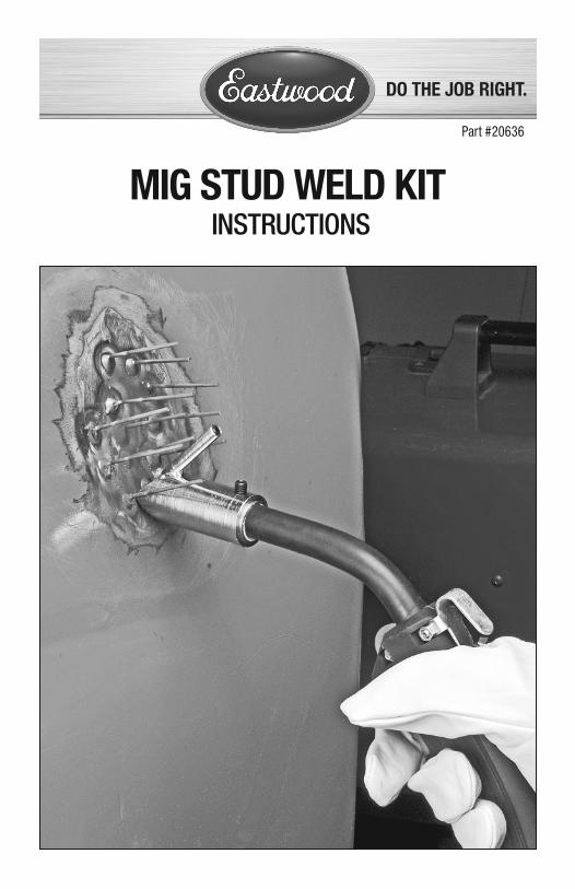
MIG STUD WELD KIT INSTRUCTIONS
Part #20636
2 Eastwood Technical Assistance: 800.544.5118 >> [email protected]
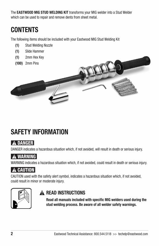
The EASTWOOD MIG STUD WELDING KIT transforms your MIG welder into a Stud Welder which can be used to repair and remove dents from sheet metal.
CONTENTSThe following items should be included with your Eastwood MIG Stud Welding Kit
(1) Stud Welding Nozzle
(1) Slide Hammer
(1) 2mm Hex Key
(100) 2mm Pins
SAFETY INFORMATION
DANGER indicates a hazardous situation which, if not avoided, will result in death or serious injury.
WARNING indicates a hazardous situation which, if not avoided, could result in death or serious injury.
CAUTION used with the safety alert symbol, indicates a hazardous situation which, if not avoided, could result in minor or moderate injury.
READ INSTRUCTIONS Read all manuals included with specific MIG welders used during the
stud welding process. Be aware of all welder safety warnings.
To order parts and supplies: 800.345.1178 >> eastwood.com 3
ELECTRIC SHOCK HAZARD!• Improper use of an electric welder can cause electric shock, injury and
death! Read all precautions described in the Welder Manual to reduce the possibility of electric shock.
• Disconnect welder from power supply before assembly, disassembly or maintenance of the torch, contact tip and when installing or removing the Stud Welding Nozzle.
• Always wear dry, protective clothing and leather welding gloves and insulated footwear. Use suitable clothing made from durable fl ame-resistant material to protect your skin.
• If other persons or pets are in the area of welding, use welding screens to protect bystanders from sparks.
• Always operate the welder in a clean, dry, well ventilated area. Do not operate the welder in humid, wet, rainy or poorly ventilated areas.
• The electrode and work (or ground) circuits are electrically “hot” when the welder is on. Do not allow these “hot” parts to come in contact with your bare skin or wet clothing.
• Separate yourself from the welding circuit by using insulating mats to prevent contact from the work surface.
• Be sure that the work piece is properly supported and grounded prior to beginning an electric welding operation.
• Always attach the ground clamp to the piece to be welded and as close to the weld area as possible. This will give the least resistance and best weld.
FIRE AND EXPLOSION HAZARD!• Electric welding produces sparks which can be discharged considerable
distances at high velocity igniting fl ammable or exploding vapors and materials.
• Do not operate electric arc welder in areas where fl ammable or explosive vapors are present.
• Do not use near combustible surfaces. Remove all fl ammable items within 35 feet of the welding area.
• Always keep a fi re extinguisher nearby while welding.
• Use welding blankets to protect painted and or fl ammable surfaces; rubber weather-stripping, dash boards, engines, etc.
• Ensure power supply has properly rated wiring to handle power usage.
SAFETY INFORMATION
4 Eastwood Technical Assistance: 800.544.5118 >> [email protected]
BURN HAZARD!• Electric welding heats metal and tools to temperatures that will cause
severe burns!
• Use protective, heat resistant gloves and clothing when using the Eastwood MIG Stud Welding Kit. Never touch work surface or Stud Welding Nozzle until it they have completely cooled.
ELECTROMAGNETIC HAZARD!• The electromagnetic fi eld that is generated during arc welding may interfere
with various electrical and electronic devices such as cardiac pacemak-ers. Anyone using such devices should consult with their physician prior to performing any electric welding operations.
• Exposure to electromagnetic fi elds while welding may have other health effects which are not known.
FUMES AND GASES HAZARD!• Fumes and gasses released during welding are hazardous. Do not breathe
fumes that are produced by the welding operation. Wear an OSHA-approved respirator when welding.
• Always work in a properly ventilated area.
• Never weld coated materials including, but not limited to: cadmium plated, galvanized, lead based paints.
ARC RAY HAZARD!• Arc rays produce intense ultraviolet radiation which can burn exposed fl esh
and cause eye damage. Use a shield with the proper fi lter (a minimum of #11) to protect your eyes from sparks and the rays of the arc when welding or when observing open arc welding (see ANSI Z49.1 and Z87.1 for safety standards).
• Use suitable clothing made from durable fl ame-resistant material to protect your skin.
• If other persons or pets are in the area of welding, use welding screens to protect bystanders from sparks and arc rays.
FLYING CHIPS HAZARD!• Grinding and sanding will eject metal chips, dust, debris and sparks at high
velocity. To prevent eye injury wear approved safety glasses.
• Wear an OSHA-approved respirator when grinding or sanding.
• Read all manuals included with specifi c grinders, sanders or other power tools used before and after the Stud Welding process. Be aware of all power tool safety warnings.
PINCH HAZARD!• Operating the Slide Hammer exerts considerable striking force in use,
which can quickly pinch fi ngers and hands. Grip and operate tool only by the hand-grip areas to avoid pinching.
To order parts and supplies: 800.345.1178 >> eastwood.com 5
SET UPTo utilize your Eastwood MIG Stud Welder Kit, you will need a MIG welder with a minimum of 100 Amp output that utilizes a Tweco style nozzle. NOTE: This was designed for Tweco-Style torches, but may work on other styles.
1. Loosen the set screws on the body of the Eastwood Stud Welding Nozzle and slide it over your gas nozzle. The Pin Holder Branch of the Eastwood Stud Welding Nozzle should be oriented as shown in (FIG 1).
2. Tighten the two set screws, with the included 2mm Hex Key, once the Stud Nozzle has been put in place but keep in mind that it may require adjustments when getting started for optimum results.
SHOCK HAZARD! All the following steps MUST be completed with the welder turned off
and uplugged.
FIG. 1FIG. 1
Stud Weld Nozzle
Set Screws
Pin Holder Branch
Set Screw
6 Eastwood Technical Assistance: 800.544.5118 >> [email protected]
OPERATIONSeveral adjustments need to be made to optimize the Eastwood MIG Stud Nozzle before it will operate properly. They are:
• Depth of MIG Gas Nozzle into the Stud Welding Nozzle.
• Set Screw Depth of Pin Holder Branch.
• Volt Setting on MIG Welder.
• Wire Speed Setting on MIG Welder.
The following wire speed chart displays starting point settings for the Eastwood MIG135, MIG175 and MIG250 welders using 0.030 wire. NOTE: These settings can vary based on electrical input, specifi c welding situation, ambient temperature, material cleanliness, and material thickness:
Once the Stud Welding Nozzle has been installed onto your torch and adjusted for proper use, the stud welding process can begin:
WELDER MIG135 MIG175 MIG250
Arc Volts I D 23
Wire Speed 6 4 260
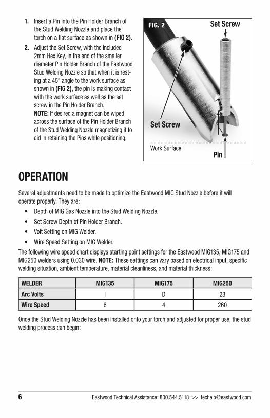
1. Insert a Pin into the Pin Holder Branch of the Stud Welding Nozzle and place the torch on a fl at surface as shown in (FIG 2).
2. Adjust the Set Screw, with the included 2mm Hex Key, in the end of the smaller diameter Pin Holder Branch of the Eastwood Stud Welding Nozzle so that when it is rest-ing at a 45° angle to the work surface as shown in (FIG 2), the pin is making contact with the work surface as well as the set screw in the Pin Holder Branch. NOTE: If desired a magnet can be wiped across the surface of the Pin Holder Branch of the Stud Welding Nozzle magnetizing it to aid in retaining the Pins while positioning.
FIG. 2FIG. 2
Set Screw
Set Screw
PinWork Surface
To order parts and supplies: 800.345.1178 >> eastwood.com 7
WELDING ON PINS1. Remove paint and any other coatings from the damaged area.
2. Insert Pin into the Pin Holder Branch of the Pin Holder Branch.
3. Place the 45° angled surface of the Stud Welding Nozzle against the panel with the Pin Holder Branch perpendicular to the working surface.
4. Hold the trigger down for ~2 seconds or until the head of the Pin is securely fused to the panel. Note: The weld bead does not need to be centered on the Pin, just securely attached to the work surface metal.
5. If the pin is not properly welded to the panel, it will easily be pulled off by the slide hammer.
6. Hold the Stud Welding Nozzle on the pin for a minimum of 3 seconds after the arc has stopped to allow the weld puddle to cool before lifting the torch.
7. Weld on as many studs as required to pull the dent.
PULLING THE PINS1. Apply the Slide hammer by slipping the open Collet on the Slide Hammer over the Pin.
2. Tighten the Collet of the Slide Hammer on the Pin by rotating the hex section until it grips the Pin. It can quickly be released by rotating the hex in the opposite direction.
3. Use a sharp, solid, outward pull on the Sliding Weight of the Slide Hammer allowing it to stop against the Hand Grip to pull the dent. Some dents will require more force than others.
4. Repeat Slide Hammer process on all of the pins in the damaged area.
BURN HAZARD! Use protective, heat-resistant gloves and clothing when using the Eastwood
MIG Stud Welding Kit. Never touch work surface or Stud Welding Nozzle until they have completely cooled.
PINCH HAZARD! Keep hands and fi ngers out from between moving components of the Slide
Hammer. Keep hands fi rmly on the Hand Grip sections of the tool only.
REMOVING THE PINS1. Once the dent has been successfully ‘pulled’, the Pins need to be removed from the surface.
The pins can be cut off near the heads and ground down using a DA Sander or Flap Disc on a Grinder. Do not allow the metal to get too hot when grinding or it could warp the panel.
APPLICATIONStud welding is a method used for removing dents in sheet metal with advantages that really stand out when using on panels where it is not possible to get to the backside with a hammer and dolly. As with many other sheet metal repair tasks it will take some practice to acquire the skill to master the Slide Hammer technique. NOTE: To avoid further damage on a project, It is strongly recommended to practice on scrap metal or damaged salvage yard parts before using on your project. To remove a dent you can follow the following basic steps:
1. Identify where the dent is located on the panel.
2. Use either a grinder with a fl ap disc or a DA Sander with 40 Grit paper to remove all of the paint. If there are deep areas with a disc cannot get into, use a wire brush on an angle grinder or drill.
3. Once all of the paint is removed, locate the lowest spots of the dent and start by adding pins to these locations.
4. Apply the Slide hammer by slipping the open Collet on the Slide Hammer over the Pin.
5. Tighten the Collet of the Slide Hammer on the Pin by rotating the hex section until it grips the Pin. It can quickly be released by rotating the hex in the opposite direction.
6. Use a sharp, solid, outward pull on the Sliding Weight of the Slide Hammer allowing it to stop against the Hand Grip to pull the dent. Some dents will require more force than others.
8 Eastwood Technical Assistance: 800.544.5118 >> [email protected]
PINCH HAZARD! Keep hands and fi ngers out from between moving components of the Slide
Hammer. Keep hands fi rmly on the Hand Grip sections of the tool only.
FLYING METAL CHIP HAZARD! Grinding and sanding will eject metal chips, dust, debris and sparks at high
velocity. To prevent eye injury wear approved safety glasses. Wear an OSHA-approved respirator when grinding or sanding. Read all manuals included with specifi c grinders, sanders or other power tools used before and after the Stud Welding process. Be aware of all power tool safety warnings.
1. Expand out and add more pins to the areas that are not as deep. These shallow areas will require fewer pins be welded.
2. Allow the metal to cool to keep from pulling the pins off the panel.
3. When choosing which pins to pull you should start at the outside of the dent and work towards the center. Ideally the dent should be repaired enough so that the maximum amount of fi ller used should be 1/16” or less.
4. If the dent is still not suffi ciently removed, re-apply pins and pull the dent more.
5. Once the dent has been repaired, the pins can be cut off near the heads and ground down using a DA Sander or Flap Disc on a Grinder. Do not allow the metal to get to hot when grinding or it could warp the panel.
6. Properly clean the surface and apply body fi ller as necessary followed by primer and a top coat.
To order parts and supplies: 800.345.1178 >> eastwood.com 9
FLYING METAL CHIP HAZARD! Grinding and sanding will eject metal chips, dust, debris and sparks at high
velocity. To prevent eye injury wear approved safety glasses. Wear an OSHA-approved respirator when grinding or sanding. Read all manuals included with specifi c grinders, sanders or other power tools used before and after the Stud Welding process. Be aware of all power tool safety warnings.
10 Eastwood Technical Assistance: 800.544.5118 >> [email protected]
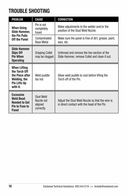
PROBLEM CAUSE CORRECTION
When Using Slide Hammer, the Pin Pulls Off the Panel
Pin is not completely fused
Make adjustments to the welder and/or the position of the Stud Weld Nozzle.
Contaminated Base Metal
Make sure the panel is free of dirt, grease, paint, wax, etc.
Slide Hammer Slips Off Pin When Operating
Gripping Collet may be clogged
Unthread and remove the hex section of the Slide Hammer, remove Collet and clean it out.
When Lifting the Torch Off the Piece after Welding, the Pin Lifts Up with It.
Weld puddle too hot
Allow weld puddle to cool before lifting the Torch off of the Pin.
Excessive Weld Bead Needed to Get Pin to Fuse to Panel
Stud Weld Nozzle not aligned correctly
Adjust the Stud Weld Nozzle so that the wire isin direct contact with the head of the Pin.
TROUBLE SHOOTING

To order parts and supplies: 800.345.1178 >> eastwood.com 11
ADDITIONAL ITEMS#13928A Replacement Pins
#12807 4-1/2" Electric Angle Grinder
#12036 Flap Disc, 4-1/2" Zirconia, 40-Grit
#11979 Eastwood Professional 7-Piece Hammer & Dolly Set

© Copyright 2016 Easthill Group, Inc. 12/15 Instruction item #20636Q Rev 0
If you have any questions about the use of this product, please contact The Eastwood Technical Assistance Service Department: 800.544.5118 >> email: [email protected]
PDF version of this manual is available online >> eastwood.com/20636manualThe Eastwood Company 263 Shoemaker Road, Pottstown, PA 19464, USA
US and Canada: 800.345.1178 Outside US: 610.718.8335Fax: 610.323.6268 eastwood.com