Embed Size (px)
Citation preview
Reading Carlson Instruments with the CR800 or CR1000 – Sensor Application Note #22 – Page 1 of 5
5 Gould Road, PO Box 2155 New London, NH 03257
Voice: (603) 526-9800 [email protected] www.canarysystems.com
Reading Carlson Instruments with the CR800 or CR1000 Sensor Application Note #22
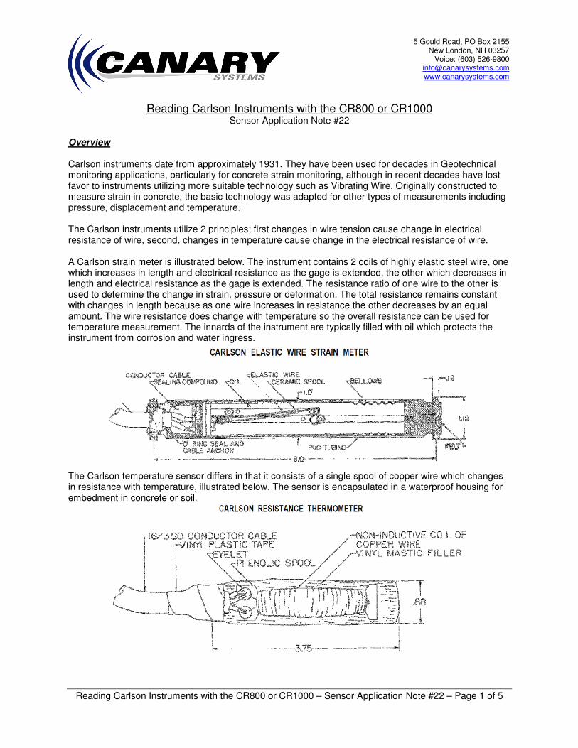
Overview Carlson instruments date from approximately 1931. They have been used for decades in Geotechnical monitoring applications, particularly for concrete strain monitoring, although in recent decades have lost favor to instruments utilizing more suitable technology such as Vibrating Wire. Originally constructed to measure strain in concrete, the basic technology was adapted for other types of measurements including pressure, displacement and temperature. The Carlson instruments utilize 2 principles; first changes in wire tension cause change in electrical resistance of wire, second, changes in temperature cause change in the electrical resistance of wire. A Carlson strain meter is illustrated below. The instrument contains 2 coils of highly elastic steel wire, one which increases in length and electrical resistance as the gage is extended, the other which decreases in length and electrical resistance as the gage is extended. The resistance ratio of one wire to the other is used to determine the change in strain, pressure or deformation. The total resistance remains constant with changes in length because as one wire increases in resistance the other decreases by an equal amount. The wire resistance does change with temperature so the overall resistance can be used for temperature measurement. The innards of the instrument are typically filled with oil which protects the instrument from corrosion and water ingress.
The Carlson temperature sensor differs in that it consists of a single spool of copper wire which changes in resistance with temperature, illustrated below. The sensor is encapsulated in a waterproof housing for embedment in concrete or soil.

Reading Carlson Instruments with the CR800 or CR1000 – Sensor Application Note #22 – Page 2 of 5
Connections The method of connection is slightly different between the typical Carlson instrument and the temperature sensor. See the following wiring diagrams for each sensor type.
Note: As R2 resistance goes higher relative to R1 the ratio will increase.
Note: The bridge completion pair is not used when measuring temperature.
Contact Canary Systems to obtain the necessary completion resistors. Precision resistors with low temperature coefficients must be obtained for accurate results.
CR800/CR1000
1L
1H
2L
Multiplexer
1H1/1HH
1L1/1L
1H2/2H
1L2/2L
Shield
2H
3L
3H0.1 ohm
VX1
AG
GageOutput
350 or 1K ohm
0.01%
350 or 1K ohm 0.01%
AG
Logger Enclosure
COM
AG
Vx
Vo
Rs1L1/1L
1H1/1H
1H2/2H
1L2/2L
Lead Wire
Lead
Wire
Note: Connection order does not match multiplexer!
Carlson Temperature
Sensor
100 ohm 0.1%
WHITE
RED
BLACK
CR800/CR1000
1L
1H
2L
Multiplexer
1H1/1H
1L1/1L
1H2/2H
1L2/2L
Shield
2H
3L
3H0.1 ohm
VX1
AG
Gage
Output
350 or 1K ohm 0.01%
350 or 1K ohm 0.01%
AG
Logger Enclosure
COM AG
Vx
Vo
Rs1L1/1L
1H1/1H
1H2/2H
1L2/2L
Lead
Wire
Lead Wire
Note: Connection order does not match
multiplexer!
Carlson Strain Meter
Note: If meter is not equipped with
Remote Sense then jumper 1L1 &
1H2
RED
WHITE
GREEN
BLACK
R1
R2
Reading Carlson Instruments with the CR800 or CR1000 – Sensor Application Note #22 – Page 3 of 5
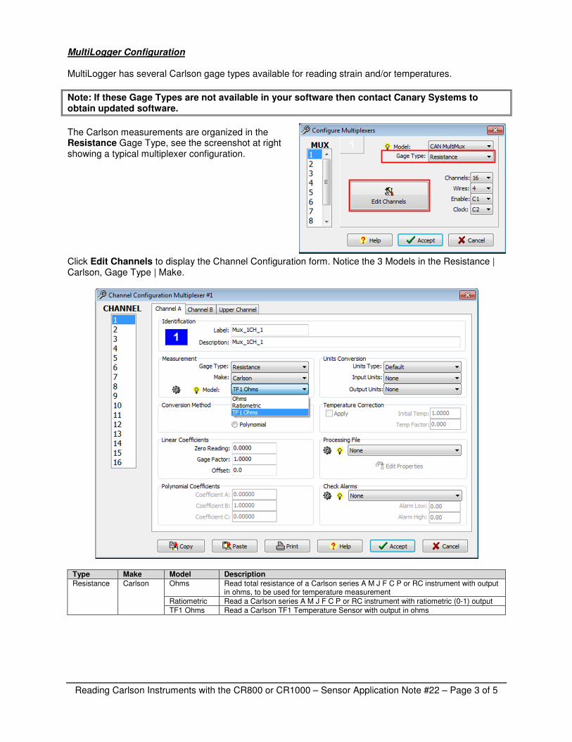
MultiLogger Configuration MultiLogger has several Carlson gage types available for reading strain and/or temperatures.
Note: If these Gage Types are not available in your software then contact Canary Systems to obtain updated software.
The Carlson measurements are organized in the Resistance Gage Type, see the screenshot at right showing a typical multiplexer configuration. Click Edit Channels to display the Channel Configuration form. Notice the 3 Models in the Resistance | Carlson, Gage Type | Make.
Type Make Model Description
Resistance Carlson Ohms Read total resistance of a Carlson series A M J F C P or RC instrument with output in ohms, to be used for temperature measurement
Ratiometric Read a Carlson series A M J F C P or RC instrument with ratiometric (0-1) output
TF1 Ohms Read a Carlson TF1 Temperature Sensor with output in ohms

Reading Carlson Instruments with the CR800 or CR1000 – Sensor Application Note #22 – Page 4 of 5
MultiLogger Channel Configuration – Strain/Pressure/Displacement Calibration data for the Carlson instrument are described in units per 0.01% ratiometric change, e.g. 3.70 µstrain/0.01% for a strain meter, 5.25 psi/0.01% for a pressure cell, etc. A pre-installation ratio is normally entered as the Zero Reading, then enter the supplied calibration factor, multiplied by 100. In the above examples, 370.0 would be entered for the strain gage, or 525.0 for the pressure cell, see example at right.
Note: The wiring diagrams and measurements automatically compensate for lead-wire resistance. The bridge output has a correction factor applied that is derived by measuring the actual bridge excitation voltage so adjustments to the Carlson calibration factors should NOT be required.
MultiLogger Channel Configuration – Temperature Calibration data for converting the total gage resistance to temperature is found on the Carlson calibration sheet. Two calibration constants are typically provided: Resistance at 0°F, e.g. 66.10 ohms. Temperature Factor, e.g. 7.84 °F/ohm These must be entered into the Channel Configuration form for each channel, example shown at right.
Note: Due to the relatively high sensitivity of the Gage Factors small unaccounted errors in the resistance measurement could negatively affect the accuracy of the resultant temperatures. This can be corrected by adjusting the Zero Reading resistance. Ideally an in-situ measurement of temperature is obtained along with the Carlson resistance measurement and the difference is used to adjust the entered Zero Reading.

Reading Carlson Instruments with the CR800 or CR1000 – Sensor Application Note #22 – Page 5 of 5
MultiLogger Channel Configuration – TF1 Temperature The nominal resistance of the Carlson TF1 temperature gage is 39 ohms at 0°F. The resistance changes at a fixed rate, 0.1 ohm per degree F. Example configuration is shown below.
Note: Due to the relatively high sensitivity of the Gage Factors small unaccounted errors in the resistance measurement could negatively affect the accuracy of the resultant temperatures. This can be corrected by adjusting the Zero Reading resistance. Ideally an in-situ measurement of temperature is obtained along with the Carlson resistance measurement and the difference is used to adjust the entered Zero Reading.