Embed Size (px)
Citation preview
Oil Tanks and PipingChapter 3
Chapter 3—Oil Tanks and Piping 3-3
IntroductionThe comfort, cleanliness and efficiency
of today’s oilheat systems rely on clean,uncontaminated fuel reaching the oilburner.To achieve this:
• Install tanks properly.
• Maintain tanks by regularly inspectingthem and fixing minor defects beforethey lead to major problems.
• Replace aging tanks before they fail.
The proper installation of an oil tank is arelatively easy process, provided it isinstalled in accordance with themanufacturer’s instructions and applicablecodes and regulations are followed.
Local codes normally require you toinstall tanks in accordance with either theirown code, the National Fire ProtectionAssociation (NFPA) or the InternationalCode Council (ICC). It’s best to check withthe local authority having jurisdiction todetermine which regulations you need tofollow.
This chapter gives an overview of oiltanks; for more detailed information, werecommend that you read NORA’s oil tankmanual, “Heating Oil Storage Tanks, Guidefor Quality Installation and Maintenance.”
Why tanks failThe most common cause of failure is
corrosion—the deterioration of the tankdue to reaction with its environment.
External corrosion is caused byelectrical activity that occurs betweendifferent parts of the tank; between the tankand its piping; or between the tank andother metals in the area. For externalcorrosion to occur, there needs to be:
1. an anode— something to give upelectrons (the tank);
2. a cathode— something to accept theelectrical flow (piping, metals in theground, etc.);
3. an electrolyte— something for theelectricity to travel through (water).
There is not much you can do to preventexternal corrosion in existing unprotectedunderground (buried) tanks. Later in thischapter, we’ll show the types of tanks thatcan stand up to the corrosion factors thatexist underground.
To reduce exterior corrosion for above-ground tanks, make sure that:
• The tank has clearance on all sides sothat debris can’t accumulate and holdmoisture against the tank.
• There is sufficient clearance under thetank so that plant growth does notcome in contact with it.
• Scratches and rust are repairedimmediately.
• The tank is painted on a regular basis.
Internal corrosion is caused by sludgeproduced by bacteria. For internal corro-
Chapter 3Oil Tanks and Piping
3-4 Oil Tanks and Piping
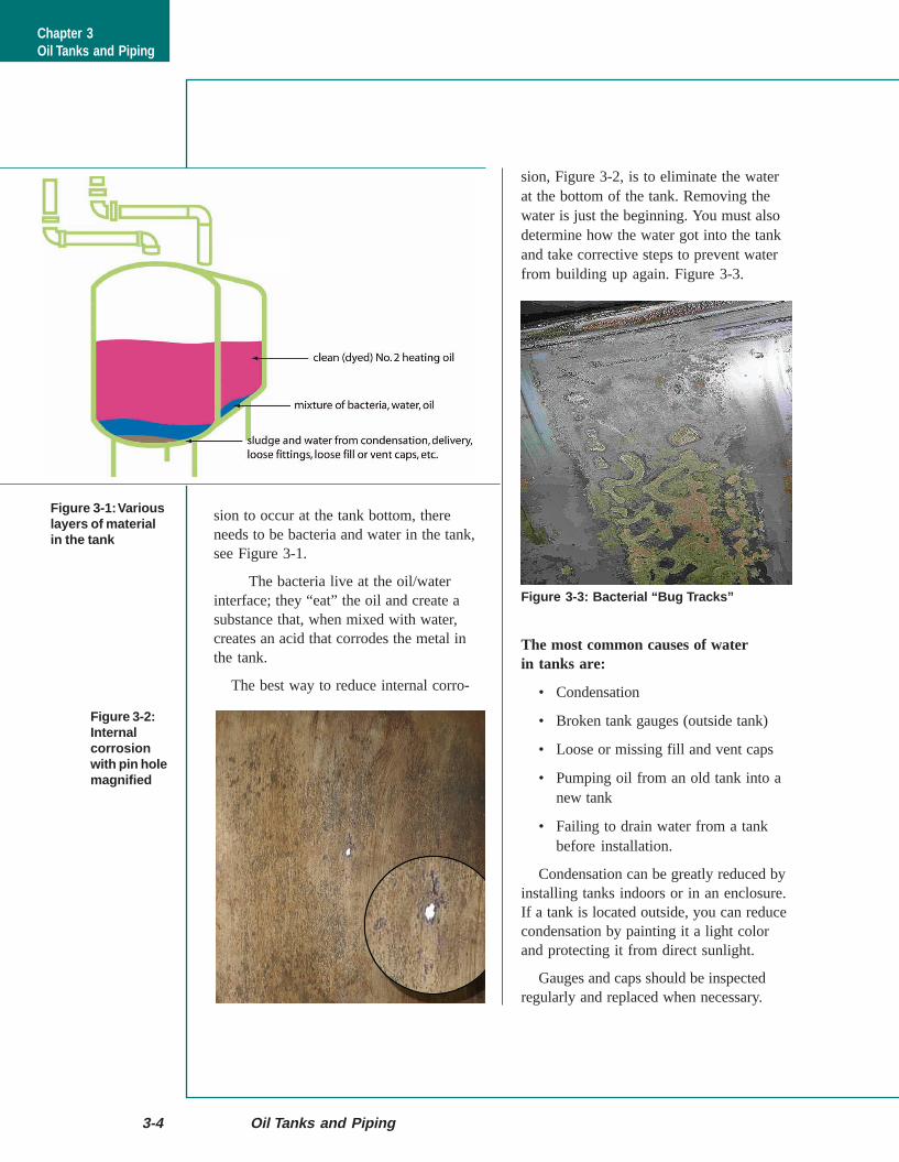
sion, Figure 3-2, is to eliminate the waterat the bottom of the tank. Removing thewater is just the beginning. You must alsodetermine how the water got into the tankand take corrective steps to prevent waterfrom building up again. Figure 3-3.
The most common causes of waterin tanks are:
• Condensation
• Broken tank gauges (outside tank)
• Loose or missing fill and vent caps
• Pumping oil from an old tank into anew tank
• Failing to drain water from a tankbefore installation.
Condensation can be greatly reduced byinstalling tanks indoors or in an enclosure.If a tank is located outside, you can reducecondensation by painting it a light colorand protecting it from direct sunlight.
Gauges and caps should be inspectedregularly and replaced when necessary.
Figure 3-1: Variouslayers of materialin the tank
Figure 3-2:Internalcorrosionwith pin holemagnified
sion to occur at the tank bottom, thereneeds to be bacteria and water in the tank,see Figure 3-1.
The bacteria live at the oil/waterinterface; they “eat” the oil and create asubstance that, when mixed with water,creates an acid that corrodes the metal inthe tank.
The best way to reduce internal corro-
Figure 3-3: Bacterial “Bug Tracks”
Chapter 3Oil Tanks and Piping
Chapter 3—Oil Tanks and Piping 3-5
Following manufacturer’s instructionswhen installing new tanks and performingthe inspection procedures described at theend of this Chapter, you will greatly reducethe amount of water-related problems andextend the lives of your customers’ tanks.
Properly installed and maintained tankscan last for several decades—much longerthan most equipment in the home. How-ever, like everything else, tanks eventuallyneed to be replaced.
Installation considerationsWhen it is time to install a new or
replacement tank—answer these threequestions:
• What size tank will be best?
• Where is the best place to install it?
• What type of tank will be best?
SizeAlthough large tanks are often installed
for delivery efficiency, an oversized tankcan cause service problems—such as:
• Poor fuel quality—fuel oil has a shelflife and deteriorates over time.
• Corrosion—larger tanks usually buildup more water from condensation.
On the other hand, tanks that are toosmall require frequent deliveries, leading toproblems during peak delivery season.
In general, the right size tank is one thatholds about one-third (1/3) of thecustomer’s annual consumption. Therefore,a customer who uses 900 gallons of oil ayear should have a 275 or 330-gallon tank.(900/3 = 300)
There may be special situations thatrequire you to install a tank that is either
larger or smaller, but in general, it is bestto apply the 1/3 rule when possible.
LocationThere are three possible locations for atank installation:
1. Inside a building—usually in thebasement, utility room or garage
2. Outside, above–ground
3. Outside, underground
Before selecting a tank location, be sureto consider regulations regardingsetbacks from:
• Heating equipment and otherignition sources
• Property lines
• Buildings, doors, windows, vents andair intakes
• Meters
Also remember to locate the tank where:• The delivery vehicle can safely park
during filling
• It will be accessible for inspectionand servicing
• An oil release will not easily enter adrain, well or waterway
• It will not be exposed to corrosionand/or damage from dripping water,falling ice, vehicles, etc.
Inside tanksNORA recommends above ground,
indoor tank installations whenever possible.These installations offer a number ofadvantages over outside tanks, including:
• The oil is usually warmer, whichmeans it burns better and won’t gel orhave cold weather performanceproblems.
Chapter 3Oil Tanks and Piping
3-6 Oil Tanks and Piping
• There are fewer temperature changes,which means the oil will last longer.
• If a leak develops, it will cause anodor, which quickly alerts us to theproblem.
• It’s easier to inspect.
• Less condensation in the tank.
It is important that you follow codes andinstructions regarding:
A. Distance from the tank to the burner(At least 5 feet.)
B. Size and height of the vent pipe
C. Size of the fill pipe
D. Fusible valve at the tank
E. Fusible valve at the burner
In addition:
1. The fill and vent lines must bepitched toward the tank
2. All tanks should have a vent alarm
3. All tanks should have a tank gauge
4. All systems should have an oil filter;it can be located at the tank, at the burneror at both the tank and burner.
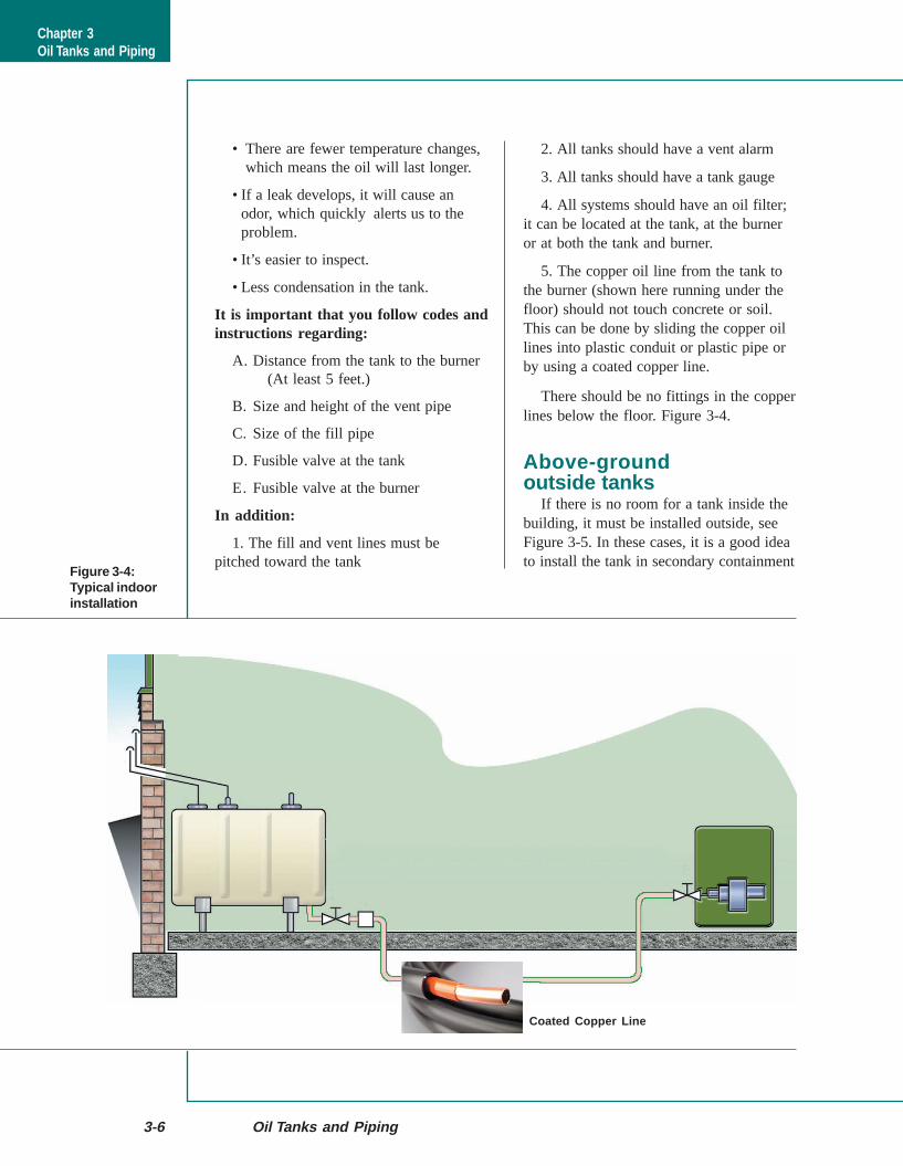
5. The copper oil line from the tank tothe burner (shown here running under thefloor) should not touch concrete or soil.This can be done by sliding the copper oillines into plastic conduit or plastic pipe orby using a coated copper line.
There should be no fittings in the copperlines below the floor. Figure 3-4.
Above-groundoutside tanks
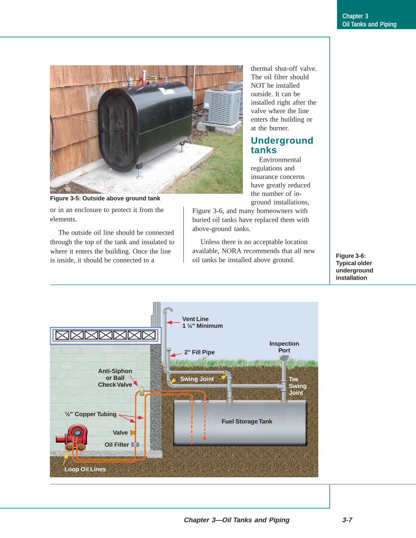
If there is no room for a tank inside thebuilding, it must be installed outside, seeFigure 3-5. In these cases, it is a good ideato install the tank in secondary containment
Figure 3-4:Typical indoorinstallation
Chapter 3Oil Tanks and Piping
Coated Copper Line
Chapter 3—Oil Tanks and Piping 3-7
or in an enclosure to protect it from theelements.
The outside oil line should be connectedthrough the top of the tank and insulated towhere it enters the building. Once the lineis inside, it should be connected to a
thermal shut-off valve.The oil filter shouldNOT be installedoutside. It can beinstalled right after thevalve where the lineenters the building orat the burner.
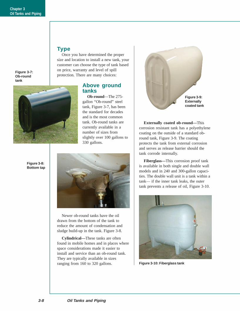
Undergroundtanks
Environmentalregulations andinsurance concernshave greatly reducedthe number of in-ground installations,
Figure 3-6, and many homeowners withburied oil tanks have replaced them withabove-ground tanks.
Unless there is no acceptable locationavailable, NORA recommends that all newoil tanks be installed above ground.
Figure 3-5: Outside above ground tank
Figure 3-6:Typical olderundergroundinstallation
Chapter 3Oil Tanks and Piping
Vent Line1 ¼" Minimum
2" Fill PipeInspection
Port
Swing Joint
Fuel Storage Tank
TeeSwingJoint
Anti-Siphonor Ball
Check Valve
½" Copper Tubing
Valve
Oil Filter
Loop Oil Lines
Externally coated ob-round—Thiscorrosion resistant tank has a polyethylenecoating on the outside of a standard ob-round tank, Figure 3-9. The coatingprotects the tank from external corrosionand serves as release barrier should thetank corrode internally.
Fiberglass—This corrosion proof tankis available in both single and double wallmodels and in 240 and 300-gallon capaci-ties. The double wall unit is a tank within atank— if the inner tank leaks, the outertank prevents a release of oil, Figure 3-10.
3-8 Oil Tanks and Piping
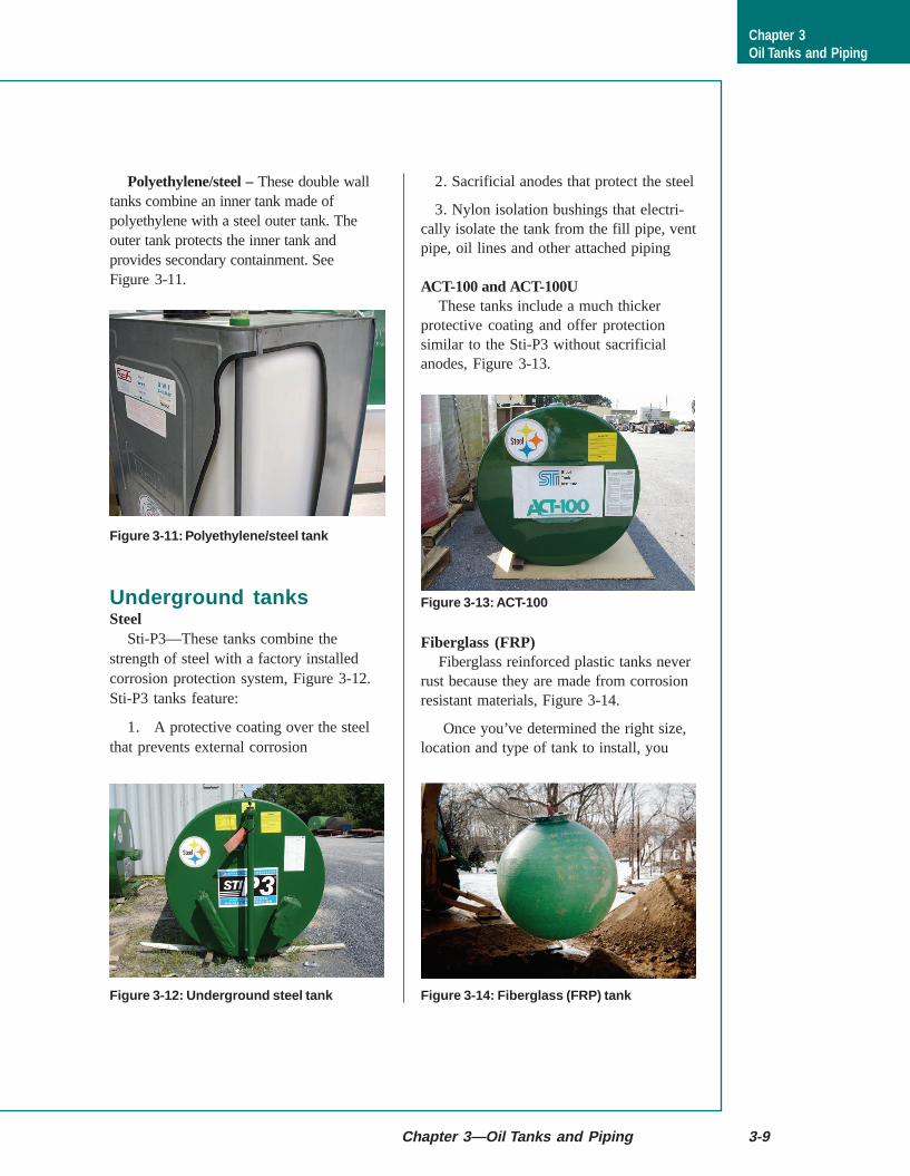
Figure 3-7:Ob-roundtank
TypeOnce you have determined the proper
size and location to install a new tank, yourcustomer can choose the type of tank basedon price, warranty and level of spillprotection. There are many choices:
Above groundtanks
Ob-round—The 275-gallon “Ob-round” steeltank, Figure 3-7, has beenthe standard for decadesand is the most commontank. Ob-round tanks arecurrently available in anumber of sizes fromslightly over 100 gallons to330 gallons.
Newer ob-round tanks have the oildrawn from the bottom of the tank toreduce the amount of condensation andsludge build-up in the tank. Figure 3-8.
Cylindrical—These tanks are oftenfound in mobile homes and in places wherespace considerations made it easier toinstall and service than an ob-round tank.They are typically available in sizesranging from 160 to 320 gallons.
Figure 3-8:Bottom tap
Figure 3-9:Externallycoated tank
Figure 3-10: Fiberglass tank
Chapter 3Oil Tanks and Piping
Polyethylene/steel – These double walltanks combine an inner tank made ofpolyethylene with a steel outer tank. Theouter tank protects the inner tank andprovides secondary containment. SeeFigure 3-11.
Underground tanksSteel
Sti-P3—These tanks combine thestrength of steel with a factory installedcorrosion protection system, Figure 3-12.Sti-P3 tanks feature:
1. A protective coating over the steelthat prevents external corrosion
2. Sacrificial anodes that protect the steel
3. Nylon isolation bushings that electri-cally isolate the tank from the fill pipe, ventpipe, oil lines and other attached piping
ACT-100 and ACT-100UThese tanks include a much thicker
protective coating and offer protectionsimilar to the Sti-P3 without sacrificialanodes, Figure 3-13.
Fiberglass (FRP)Fiberglass reinforced plastic tanks never
rust because they are made from corrosionresistant materials, Figure 3-14.
Once you’ve determined the right size,location and type of tank to install, you
Chapter 3—Oil Tanks and Piping 3-9
Figure 3-11: Polyethylene/steel tank
Figure 3-12: Underground steel tank
Figure 3-13: ACT-100
Figure 3-14: Fiberglass (FRP) tank
Chapter 3Oil Tanks and Piping
3-10 Oil Tanks and Piping
must become thoroughlyfamiliar with the currentversion of the manufacturer’sinstallation instructions beforeyou begin an installation.
Installationprocedures
Be sure to follow themanufacturer’s installationinstructions and all applicablecodes and regulations during
the installation. Thisnext section emphasizessome of the importantsteps in tank installation process.
Work neatProtect the customer’s property
and the components that you areinstalling. It is much easier toprevent a mess than to clean it up.Cover work areas with drop cloths orbuilder’s paper or other material,Figure 3-14.
Piping connectionsIt is imperative that all connections are
made tight and leak proof. All threadedconnections should be joined with a pipecompound that is non-teflon, oil resistant,and remains flexible. Be careful whenapplying pipe compound and make sure towipe away excess compound so it does notget into the tank or oil lines.
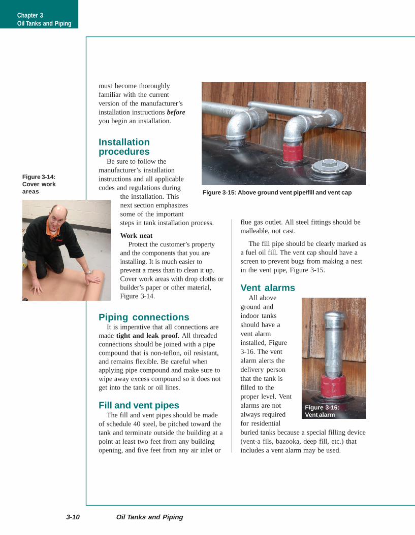
Fill and vent pipesThe fill and vent pipes should be made
of schedule 40 steel, be pitched toward thetank and terminate outside the building at apoint at least two feet from any buildingopening, and five feet from any air inlet or
flue gas outlet. All steel fittings should bemalleable, not cast.
The fill pipe should be clearly marked asa fuel oil fill. The vent cap should have ascreen to prevent bugs from making a nestin the vent pipe, Figure 3-15.
Vent alarmsAll above
ground andindoor tanksshould have avent alarminstalled, Figure3-16. The ventalarm alerts thedelivery personthat the tank isfilled to theproper level. Ventalarms are notalways requiredfor residentialburied tanks because a special filling device(vent-a fils, bazooka, deep fill, etc.) thatincludes a vent alarm may be used.
Figure 3-14:Cover workareas Figure 3-15: Above ground vent pipe/fill and vent cap
Figure 3-16:Vent alarm
Chapter 3Oil Tanks and Piping
Chapter 3—Oil Tanks and Piping 3-11
Oil linesFor normal residential use, 1/2" O.D. oil
lines are recommended. Copper oil linesshould be connected with flare fittings.Compression fittings must not be used(“slip fittings”, where the oil line enters thetop of the tank, are the exception and areacceptable).
Oil lines should have as few fittings aspossible and all fittings should be acces-sible.
Thermal shutoff valvesIndoor tanks should have a thermal
safety shutoff (Firomatic®) valve in thesuction line at the tank, see Figure 3-17.Outside tanks should have a shut off valvewhere the suction line enters the inside ofthe building.
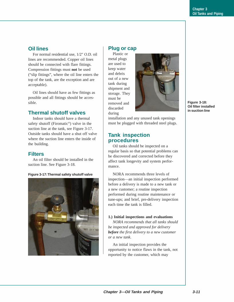
FiltersAn oil filter should be installed in the
suction line. See Figure 3-18.
Plug or capPlastic or
metal plugsare used tokeep waterand debrisout of a newtank duringshipment andstorage. Theymust beremoved anddiscardedduringinstallation and any unused tank openingsmust be plugged with threaded steel plugs.
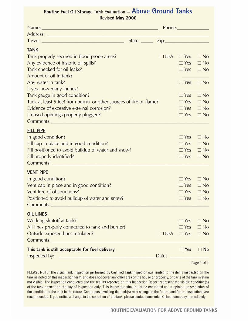
Tank inspectionprocedures
Oil tanks should be inspected on aregular basis so that potential problems canbe discovered and corrected before theyaffect tank longevity and system perfor-mance.
NORA recommends three levels ofinspection—an initial inspection performedbefore a delivery is made to a new tank ora new customer; a routine inspectionperformed during routine maintenance ortune-ups; and brief, pre-delivery inspectioneach time the tank is filled.
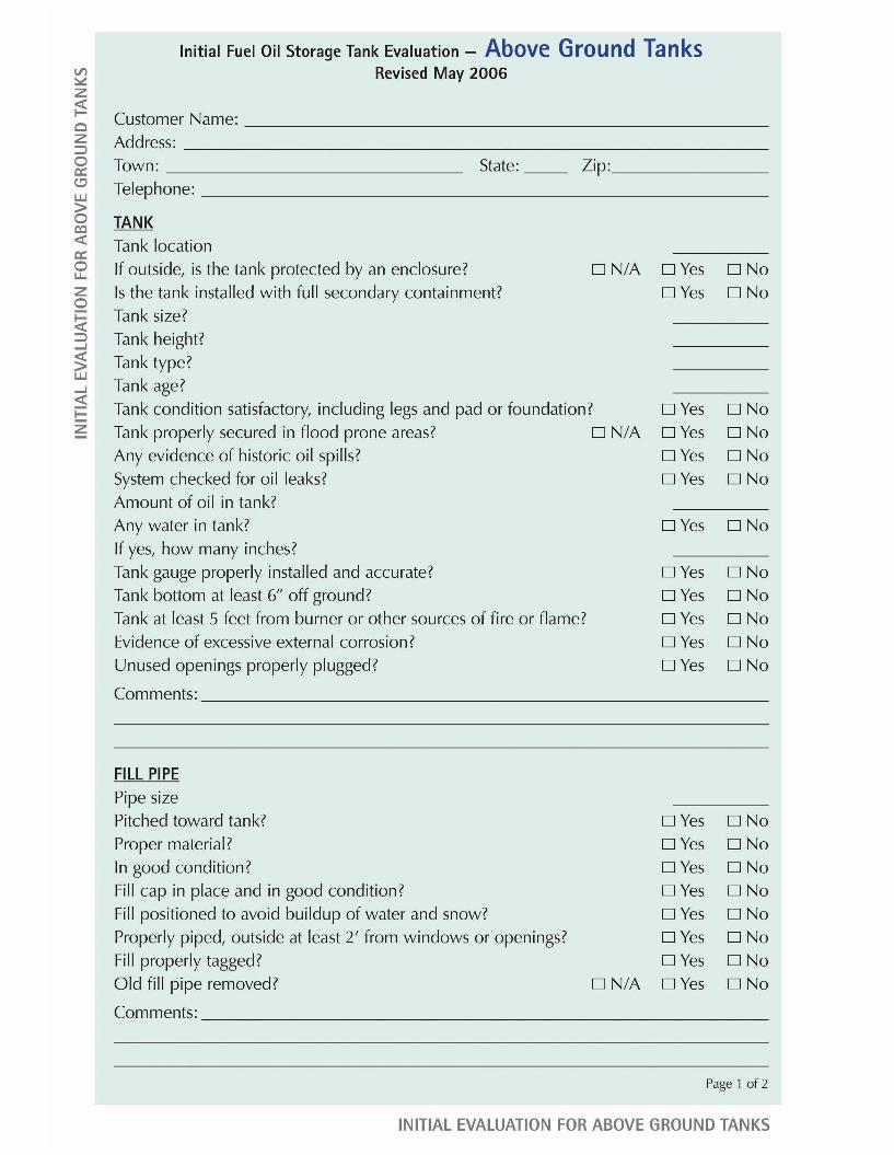
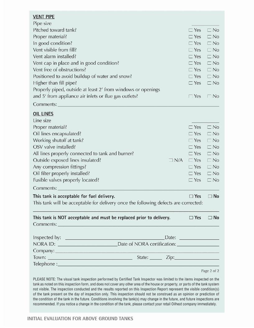
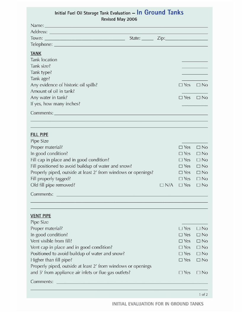
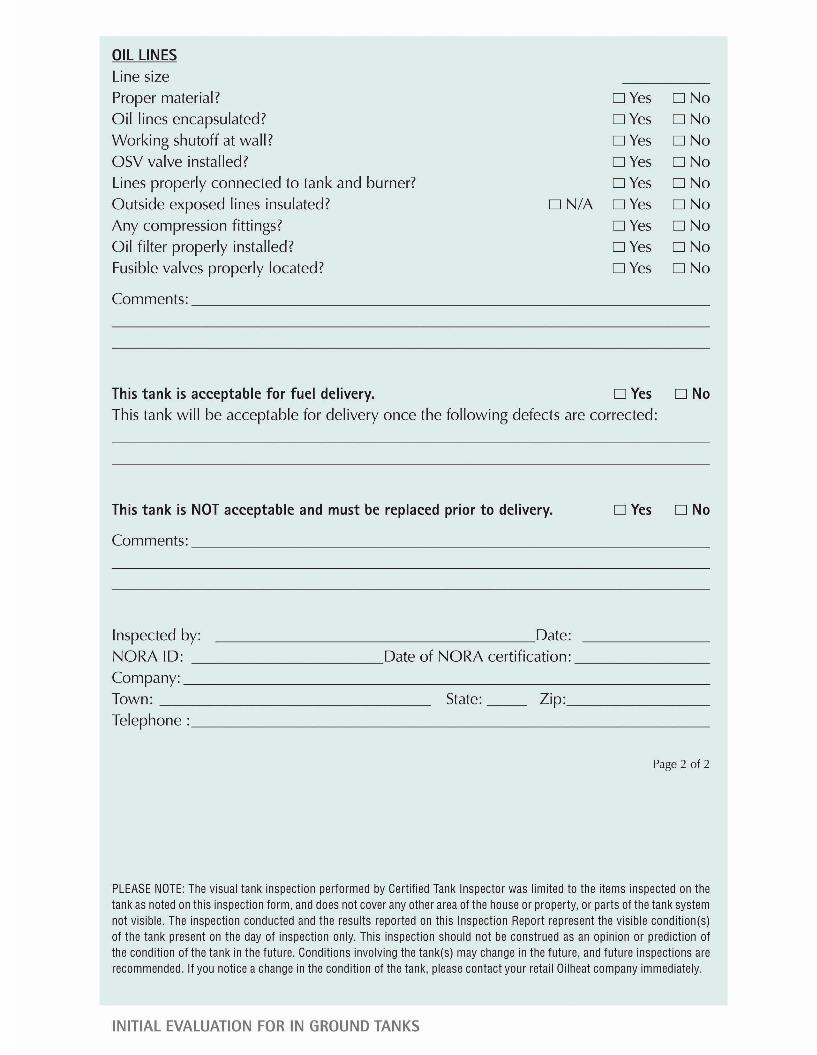
1.) Initial inspections and evaluationsNORA recommends that all tanks should
be inspected and approved for deliverybefore the first delivery to a new customeror a new tank.
An initial inspection provides theopportunity to notice flaws in the tank, notreported by the customer, which may
Figure 3-18:Oil filter installedin suction line
Figure 3-17: Thermal safety shutoff valve
Chapter 3Oil Tanks and Piping
prevent a problem in the future. It will alsoensure that the fill and vent pipes areproperly connected and correctly identified.
In those cases where a new tank has beeninstalled for an existing customer, the tankinspection should include procedures toensure that inactive fill and vent pipes havebeen removed.
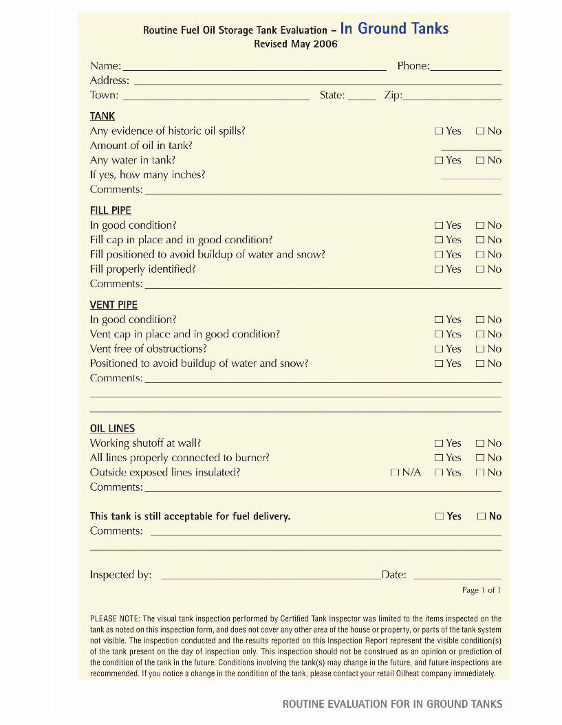
The inspections are different for above-ground tanks and buried tanks.
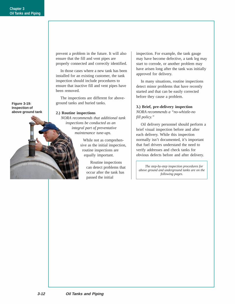
2.) Routine inspectionsNORA recommends that additional tank
inspections be conducted as anintegral part of preventative
maintenance tune-ups.
While not as comprehen-sive as the initial inspection,routine inspections areequally important.
Routine inspectionscan detect problems thatoccur after the tank haspassed the initial
3-12 Oil Tanks and Piping
inspection. For example, the tank gaugemay have become defective, a tank leg maystart to corrode, or another problem mayhave arisen long after the tank was initiallyapproved for delivery.
In many situations, routine inspectionsdetect minor problems that have recentlystarted and that can be easily correctedbefore they cause a problem.
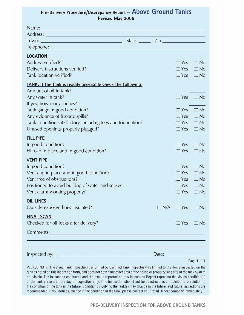
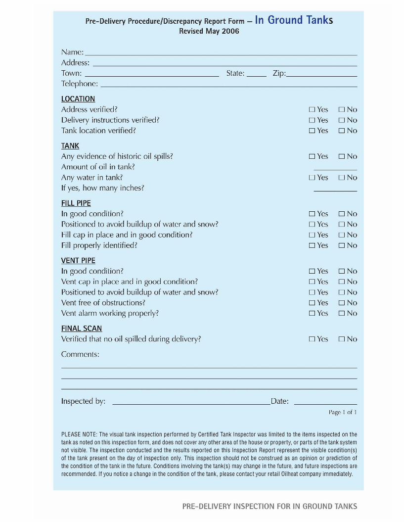
3.) Brief, pre-delivery inspectionNORA recommends a “no-whistle-nofill policy.”
Oil delivery personnel should perform abrief visual inspection before and aftereach delivery. While this inspectionnormally isn’t documented, it’s importantthat fuel drivers understand the need toverify addresses and check tanks forobvious defects before and after delivery.
Figure 3-19:Inspection ofabove ground tank
Chapter 3Oil Tanks and Piping
The step-by-step inspection procedures forabove ground and underground tanks are on the
following pages.
Chapter 3—Oil Tanks and Piping 00