Embed Size (px)
Citation preview
OPERATION MANUAL
The information in this document is subject to change without notice and does not represent a commitment on the part of Native Instruments GmbH. The software described by this document is subject to a License Agreement and may not be copied to other media. No part of this publication may be copied, reproduced or otherwise transmitted or recorded, for any purpose, without prior written permission by Native Instruments GmbH, hereinafter referred to as Native Instruments. All product and company names are ™ or ® trademarks of their respective owners.
KORE SOUND is a ® trademark of NATIVE INSTRUMENTS.
Users Guide written by Aleksander Rebane
Document version: 1.0.1 (12/2008)
Software version: 1.0.1
Special thanks to the Beta Test Team, who were invaluable not just in tracking down bugs, but in making this a better product.
Germany
NATIVE INSTRUMENTS GmbH
Schlesische Str. 28
D-10997 Berlin
Germany
www.native-instruments.de
USA
NATIVE INSTRUMENTS North America, Inc.
5631 Hollywood Boulevard
Los Angeles, CA 90028
USA
www.native-instruments.com
MASSIVE was designed and developed entirely by Native Instruments GmbH. Solely the name Massive is a registered trademark of Massive Audio Inc, USA.
© Native Instruments GmbH, 2008. All rights reserved.
GETTING STARTED – �
1. Welcome to REAKTOR SPARK!Thank you very much for purchasing REAKTOR SPARK. On behalf of the entire NATIVE INSTRUMENTS team, we hope that this KORE SOUNDPACK will truly inspire you.
REAKTOR SPARK contains 200 new KORE SOUNDS®, based on a newly designed REAKTOR ensemble. These sounds have been designed to integrate seamlessly into your KORE SOUND database, making them easily accessible. Also, like the KORE 2/KORE PLAYER factory content, all KORE SOUNDPACKS utilize the KORE 2/KORE PLAYER’s Integrated Engines: You only need KORE 2 or KORE PLAYER to make full use of their sonic capabilities. Furthermore, the sounds have been equipped with dedicated Control Page assignments, putting the most important musical parameters right at your fingertips. Individual Sound Variations have been created for each KORE SOUND of this product, adding to the number of preconfigured sounds.
This manual will help you get started with your KORE SOUNDPACK. If you want to start immediately, proceed to the Installation and Activation section. Please read that chapter carefully and fully, as it explains all the steps required to integrate the KORE SOUNDPACK into KORE 2/KORE PLAYER. Following the Installation chapter is an explanation of how to use the KORE SOUNDS within KORE 2/KORE PLAYER. If you are already familiar with KORE 2/KORE PLAYER, this will be straightforward, but it might be worth a look nonethe-less. Finally, the last section of this manual adds some more details regarding the sounds that come with REAKTOR SPARK.
GETTING STARTED – 5
2. What is REAKTOR SPARK?REAKTOR SPARK puts a large collection of production-ready sounds for contemporaryputs a large collection of production-ready sounds for contemporary music production directly under your fingertips: REAKTOR SPARK has it all, from pad to lead sounds, from percussive keyboards to floating soundscapes. The variety becomes possible due to the specifically designed REAKTOR ensemble SPARK, whose internal feedback structure gives the characteristic sonic touch to the Soundpack.
When loading a KORE SOUND from this collection, KORE 2/KORE PLAYER automatically loads its Integrated Engines and adjusts the specific sound. This all happens automatically, with no additional adjustments necessary.
After loading the sound, you are ready to tweak it. The Control Pages and Sound Variations, preassigned for each KORE SOUND, enable you to adjust each sound to your production needs or simply morph from one sound world to another.
GETTING STARTED – 6
3. Installation and ActivationThe following section explains how to install and activate REAKTOR SPARK. Although this process is straightforward, please take a minute to read these instructions, as doing so might prevent some common problems.
3.1 Installing REAKTOR SPARK
After downloading the KORE SOUNDPACK, unzip the compressed archive you received from NATIVE INSTRUMENTS. It contains this documentation as a PDF file, as well as an installer application.
To install REAKTOR SPARK, double-click the installer application and follow the instruc-tions on the screen. The installer application automatically places the new KORE SOUND content files into the folders that KORE 2/KORE PLAYER expects them to be in. In the course of the installation procedure, the installer application will ask you to specify another folder for additional files, like this manual.
All sounds coming with REAKTOR SPARK can be used directly within KORE 2 or KORE PLAYER, which use the Integrated Engines to actually load and play the sounds. If you own REAKTOR, you can also load the SPARK ensemble directly into Reaktor.
GETTING STARTED – 7
3.2 Activating REAKTOR SPARK
When installation is finished, start the SERVICE CENTER that was installed with KORE 2/KORE PLAYER. It will connect your computer to the Internet and activate your REAKTOR SPARK installation. In order to activate your copy of REAKTOR SPARK, you have to perform the following steps within the SERVICE CENTER:
Log in: Enter your NATIVE INSTRUMENTS user account name and password on the initial page. This is the same account information you used in the NATIVE INSTRUMENTS Online Shop, where you bought your KORE SOUNDPACK, and for other NATIVE INSTRUMENTS product activations.
Select products: The Service Center detects all products that have not yet been acti-vated and lists them. You can activate multiple products at once — for example, KORE 2/KORE PLAYER and your KORE SOUNDPACK, or several KORE SOUNDPACKS.
Activate: After proceeding to the next page, the Service Center connects to the NATIVE INSTRUMENTS server and activates your products.
Download updates: When the server has confirmed the activation, the Service Center automatically displays the Update Manager with a list of all available updates for your installed products. Please make sure that you always use the latest version of your NATIVE INSTRUMENTS products to ensure proper functioning.
Now, you are ready to use REAKTOR SPARK. Please start KORE 2/KORE PLAYER in the standalone mode. This will trigger the database update process automatically and integrate the new KORE SOUNDS into KORE 2/KORE PLAYER’s database. The next chapter will explain how to use the new sounds in KORE 2/KORE PLAYER.
1.
2.
3.
4.
! A c t i v a t i o n o f K O R E SOUNDPACKS is optional.
However, it will give you access to free updates.
! A c t i v a t i o n o f K O R E SOUNDPACKS is optional.
However, it will give you access to free updates.
! Downloading updates is option-al. After activation is complete,
you can always quit the Service Center.!
Downloading updates is option-al. After activation is complete,
you can always quit the Service Center.
GETTING STARTED – 8
4. How to use REAKTOR SPARKThe following sections will give you a brief overview over some basic operations: you will learn how to search for sounds you have in mind and how to load and play KORE SOUNDS. For details about these topics please read the KORE 2/KORE PLAYER manual.
4.1 Finding a KORE SOUND
All REAKTOR SPARK KORE SOUNDS are directly integrated into KORE 2’s/KORE PLAYER’s database. They will show up in the Browser’s Search Results List alongside all the other sounds that match your specific search criteria — for example, a combination of Attributes. To restrict your search results to your specific pack’s sounds, select the desired pack in the SOUNDPACK column of the Attributes List. The Search Results List shows the entire content of this particular pack.
There is another way to restrict your search results to your specific pack’s sounds: simply enter the KORE SOUNDPACK’s name into the Quick Search Field of the Browser, or even just a part of the name — for example, “spark”. The corresponding KORE SOUNDS au-tomatically appear in the Search Results List.
If you don’t want to limit the results to this KORE SOUNDPACK, but do want to have the display grouped by SOUNDPACKS, you can show the bank name within the Search Results List and sort the list according to this entry. To do so, right-click the Search Results List’s header row and activate the Bank entry in the upcoming context menu. This will show each KORE SOUND’s bank name in a new column of the Search Results List. Now click the Bank column’s header to sort the list according to this specification. This will group the results.
! KORE 2 users: if the Soundpack column is not visible in the
Attributes List, right-click on the Attributes List header and select the Soundpack entry in the upcoming con-text menu.
! KORE 2 users: if the Soundpack column is not visible in the
Attributes List, right-click on the Attributes List header and select the Soundpack entry in the upcoming con-text menu.
GETTING STARTED – 9
4.2 Loading the KORE SOUND
4.2.1 Loading the KORE SOUND in KORE PLAYERAfter you have located your KORE SOUND, load it by double-clicking its Search Results List entry. Alternatively, drag it onto KORE PLAYER’s Global Controller. Both actions replace the currently loaded KORE SOUND — if it is the first KORE SOUND you are loading after start-up, it will replace an “empty” KORE SOUND.
When loaded, the KORE SOUND will automatically be displayed so that its Control Pages are directly mapped onto the Global Controller. For each KORE SOUND, a User Page has been pre-assigned, granting direct access to the KORE SOUND’s most important param-eters. The exact buttons and knobs assignments on the Control Page are specific to each KORE SOUND, as well as the number of Control Pages. With the Global Controller, you also have immediate control of the KORE SOUND’s Sound Variations. Please refer to the KORE PLAYER manual for details about Control Pages and Sound Variations.
If you are using KORE PLAYER as a plug-in in a host environment, you can save the posi-tions/states that you set on the eight knobs and eight buttons of the Control Page: sav-ing the host’s project saves all settings of all incorporated plug-ins (among others, KORE PLAYER) and thus all changes you made to the loaded KORE SOUND.
4.2.2 Loading the KORE SOUND in KORE 2After you have located your KORE SOUND, load it by double-clicking its Search Results List entry. Alternatively, drag it onto KORE 2’s Global Controller. Both actions will replace the currently focused KORE SOUND — if it is the first KORE SOUND you load after start-up, it will replace an “empty” KORE SOUND. If you want to place the KORE SOUND into a specific Channel Insert within the Edit Area (instead of loading the KORE SOUND into the focused one), you can also drag it directly into the Sound Matrix.
The exact buttons and knobs assignments on the User Page are specific to each KORE SOUND. With the Global Controller, you also have immediate control of the KORE SOUND’s Sound Variations. Please refer to the KORE 2/KORE PLAYER manual for details about Control Pages and Sound Variations.
GETTING STARTED – 10
If you have the full version of the Integrated Engine installed, you can also open the engine itself. Just click the Plug-in editor icon within the Global Controller, or double-click the Channel Insert within the Sound Matrix. This will give you full access to all parameters of the KORE SOUND, exceeding the options in KORE 2’s Control Pages. Note that this will change the status of the KORE SOUND: After you have opened a KORE SOUND using its associated plug-in editor, it will always require the respective plug-in’s fully licensed version to be installed. (Of course, opening the KORE SOUND in the plug-in’s full version does not alter the original KORE SOUND file, but creates a copy that you might want to save as a separate file later.) If you do not use the full editor for editing a KORE SOUND, but instead only use the Control Pages and the Sound Variations, the KORE SOUND will again be loadable without the full license available.
After you have tweaked the KORE SOUND to your liking, you can save it to the User Sounds content by dragging it back onto the Search Results List — just the opposite of the loading process. Within the Save List, you can edit the KORE SOUND’s name, enter your name as the KORE SOUND’s author and so on. When finished, click the done Button to save the KORE SOUND to the database. It is now available for each project you are working on.
Alternatively, the KORE SOUND and all changes you made are also saved when you store the Performance of KORE 2. However, the KORE SOUND is not automatically added to the Browser’s database. The same happens if you are using KORE 2 as a plug-in: saving the host’s project saves all settings of all incorporated plug-ins (like KORE 2) and thus all changes you made to the loaded KORE SOUND.
% If these terms are completely new to you, chapter 3.1 of
the KORE 2 manual provides general information, and chapter 3.1.� covers the Control Page system and Sound Variations.
% If these terms are completely new to you, chapter 3.1 of
the KORE 2 manual provides general information, and chapter 3.1.� covers the Control Page system and Sound Variations.
GETTING STARTED – 11
5. Content DescriptionThe following paragraphs briefly describe the REAKTOR SPARK content. However, listening to the KORE SOUNDS tells much more than mere words. These descriptions will give you a starting point, but you’ll probably learn most about this KORE SOUNDPACK by using it!
The REAKTOR SPARK provides you with a diverse collection of dynamic and expressiveprovides you with a diverse collection of dynamic and expressive sounds based on the new and innovative SPARK ensemble. These sounds can range from saucy synth leads to vibrant percussive sounds or play the role of quasi-chaotically evolvingchaotically evolving evolving pads, but all of them have one thing in common: they readily respond to your individual way of playing. In either a studio environment or a live performance situation, the soundsIn either a studio environment or a live performance situation, the sounds included in the REAKTOR SPARK can be used in Rock, Jazz, Industrial, Psychedelic, Sound Tracks, and various electronic genres ranging from Electro to IDM… But the musical genre is actually not important: It’s all up to you!
The following sections describe how you can use these sounds in KORE or KORE PLAYER. If you also own REAKTOR, you can access SPARK’s control panel as well. The details about using SPARK are given within the “Using SPARK in REAKTOR” and “SPARK Control Reference” sections below.
GETTING STARTED – 12
5.1 The SPARK Ensemble
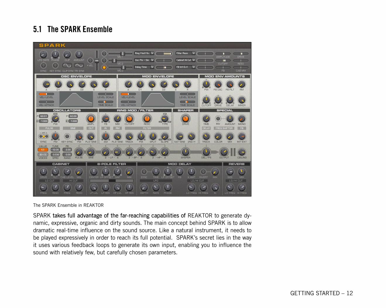
The SPARK Ensemble in REAKTOR
SPARK takes full advantage of the far-reaching capabilities oftakes full advantage of the far-reaching capabilities of REAKTOR to generate dy-namic, expressive, organic and dirty sounds. The main concept behind SPARK is to allow dramatic real-time influence on the sound source. Like a natural instrument, it needs to be played expressively in order to reach its full potential. SPARK’s secret lies in the way it uses various feedback loops to generate its own input, enabling you to influence the sound with relatively few, but carefully chosen parameters.
GETTING STARTED – 13
5.2 Using SPARK in KORE or KORE PLAYER
Allll REAKTOR SPARK sounds share the same control interface within KORE 2’s or KORE PLAYER’s Global Controller: the SPARK Synth Essentials Page, the SPARK Mix & FX Essentials Page, the SPARK More Synth & FX Page, and the SPARK Macro Controls & LFO Page.
5.2.1 SPARK Synth Essentials Page
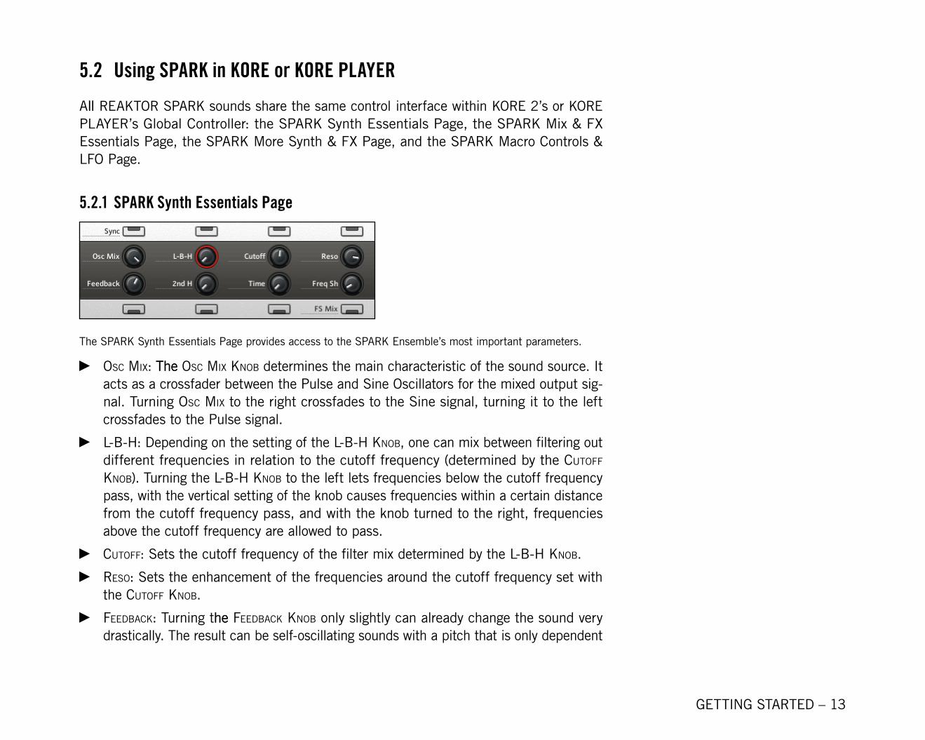
The SPARK Synth Essentials Page provides access to the SPARK Ensemble’s most important parameters.
oSc Mix: TheThe oSc Mix knoB determines the main characteristic of the sound source. It acts as a crossfader between the Pulse and Sine Oscillators for the mixed output sig-nal. Turning oSc Mix to the right crossfades to the Sine signal, turning it to the left crossfades to the Pulse signal.
l-B-h: Depending on the setting of the l-B-h knoB, one can mix between filtering out different frequencies in relation to the cutoff frequency (determined by the cutoFF knoB). Turning the l-B-h knoB to the left lets frequencies below the cutoff frequency pass, with the vertical setting of the knob causes frequencies within a certain distance from the cutoff frequency pass, and with the knob turned to the right, frequencies above the cutoff frequency are allowed to pass.
cutoFF: Sets the cutoff frequency of the filter mix determined by the l-B-h knoB.
reSo: Sets the enhancement of the frequencies around the cutoff frequency set with the cutoFF knoB.
FeedBack: Turning thehe FeedBack knoB only slightly can already change the sound very drastically. The result can be self-oscillating sounds with a pitch that is only dependent
►
►
►►
►
GETTING STARTED – 1�
on the cutoff frequency (determined by the cutoFF knoB), or sounds resembling acous-tic feedbacks of microphones, speakers, or guitar amps.
2nd h: Lets you change the harmonic content of the signal by wave-shaping. At zero the shaping curves are symmetric, creating mainly odd harmonics. With larger values the curve gets increasingly asymmetric and the amount of the 2nd and other even harmonics is increased.
tiMe: The tiMe knoB sets the delay time of the voice delay. It has a big influence on which frequencies will be excited in the feedback path by the application of a delay. You can use the delay also in the signal that is routed to the Effects section, just mix it with the other output signals by using the del + F knoB in the SPARK Mix & FX Essentials Page to get a coloring or chorusing effect.
FreQ Sh: All frequencies entering the frequency shifter are shifted by the value set by the FreQ Sh knoB. This usually results in an inharmonic or phasing sound.
FS Mix: The effect of the frequency shifter controlled by the FreQ Sh knoB can be turned on and off with the FS Mix Button.
Sync: This controls the hard synchronization of the Pulse oscillator to the feedback signal.
5.2.2 SPARK Mix & FX Essentials Page
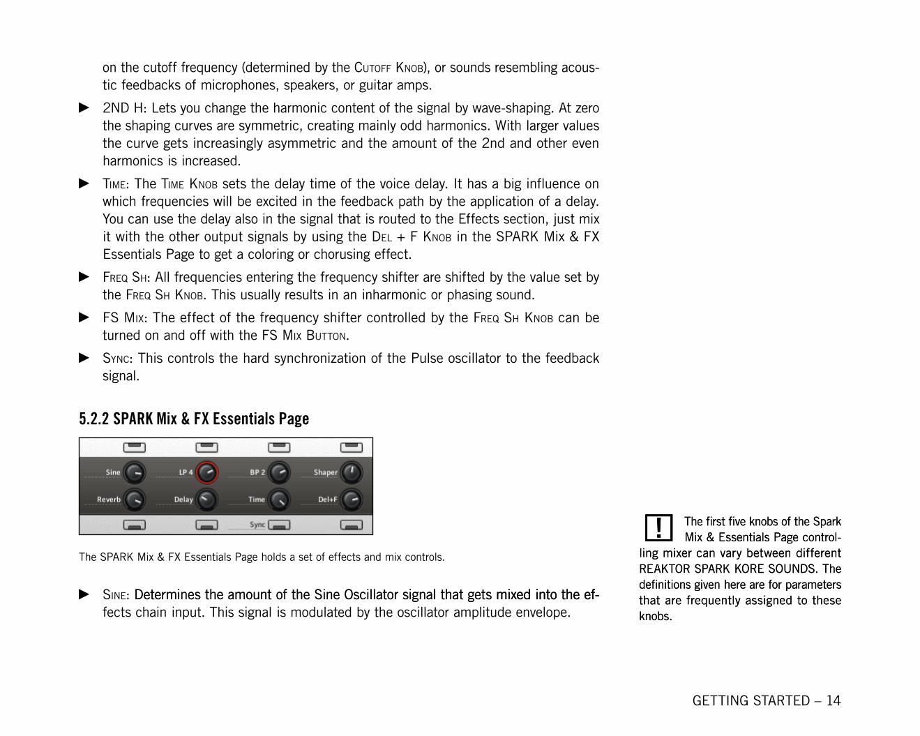
The SPARK Mix & FX Essentials Page holds a set of effects and mix controls.
Sine: Determines the amount of the Sine Oscillator signal that gets mixed into the ef-Determines the amount of the Sine Oscillator signal that gets mixed into the ef- mixed into the ef-fects chain input. This signal is modulated by the oscillator amplitude envelope.
►
►
►
►
►
►
! The first five knobs of the Spark Mix & Essentials Page control-
ling mixer can vary between different REAKTOR SPARK KORE SOUNDS. The definitions given here are for parameters that are frequently assigned to these knobs.
! The first five knobs of the Spark Mix & Essentials Page control-
ling mixer can vary between different REAKTOR SPARK KORE SOUNDS. The definitions given here are for parameters that are frequently assigned to these knobs.
GETTING STARTED – 15
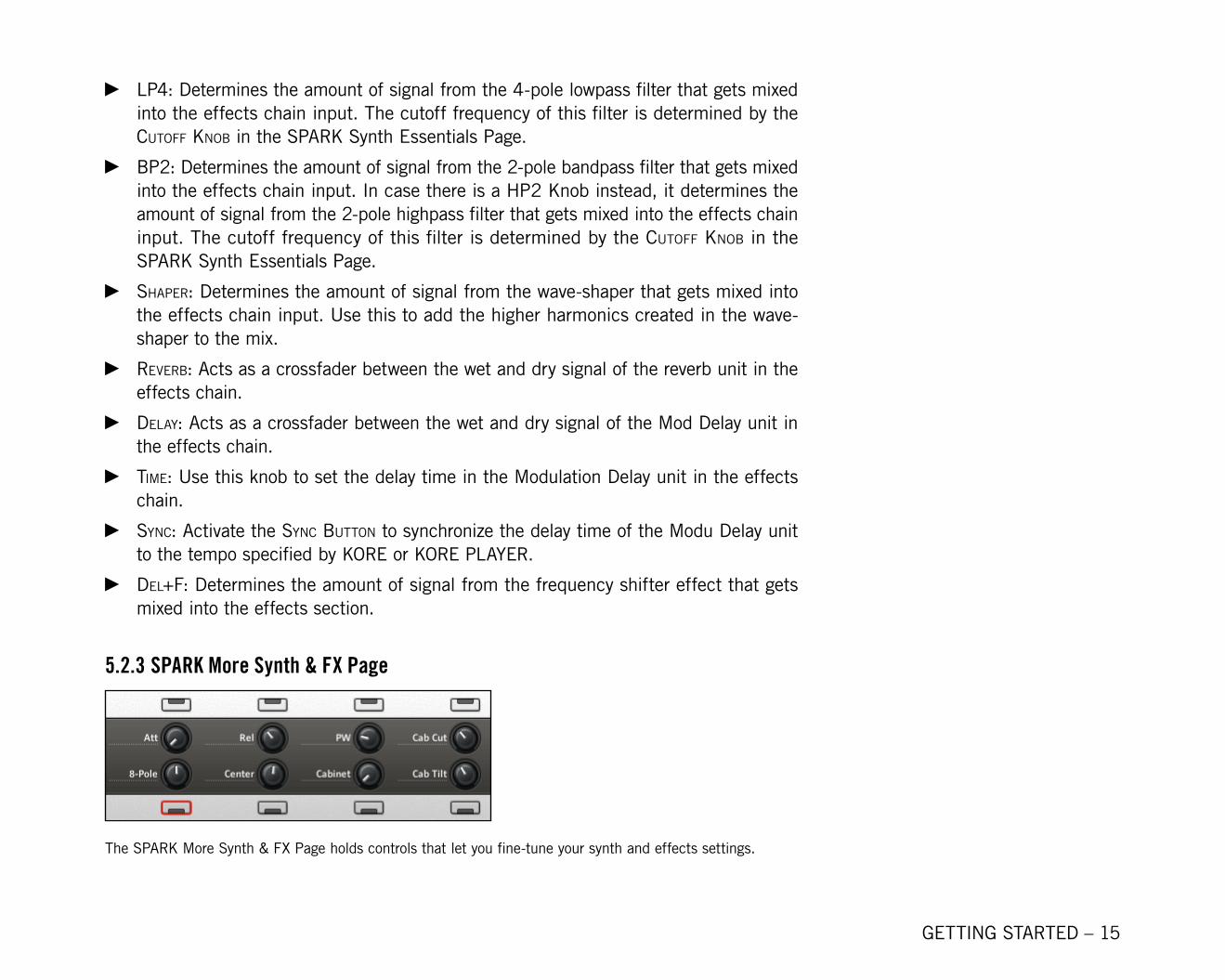
lP4: Determines the amount of signal from the 4-pole lowpass filter that gets mixed into the effects chain input. The cutoff frequency of this filter is determined by the cutoFF knoB in the SPARK Synth Essentials Page.
BP2: Determines the amount of signal from the 2-pole bandpass filter that gets mixed into the effects chain input. In case there is a HP2 Knob instead, it determines the amount of signal from the 2-pole highpass filter that gets mixed into the effects chain input. The cutoff frequency of this filter is determined by the cutoFF knoB in the SPARK Synth Essentials Page.
ShaPer: Determines the amount of signal from the wave-shaper that gets mixed into the effects chain input. Use this to add the higher harmonics created in the wave-shaper to the mix.
reverB: Acts as a crossfader between the wet and dry signal of the reverb unit in the effects chain.
delay: Acts as a crossfader between the wet and dry signal of the Mod Delay unit in the effects chain.
tiMe: Use this knob to set the delay time in the Modulation Delay unit in the effects chain.
Sync: Activate the Sync Button to synchronize the delay time of the Modu Delay unit to the tempo specified by KORE or KORE PLAYER.
del+F: Determines the amount of signal from the frequency shifter effect that gets mixed into the effects section.
5.2.3 SPARK More Synth & FX Page
The SPARK More Synth & FX Page holds controls that let you fine-tune your synth and effects settings.
►
►
►
►
►
►
►
►
GETTING STARTED – 16
att: Controls the time the amplitude envelope of the Sine and Pulse oscillators takes to reach the peak value after the key is pressed. Higher values yield higher times.
rel: Controls the time the amplitude envelope of the Sine and Pulse oscillators takes to reach zero after the key is released. Higher values yield higher times.
PW: The PW Knob determines the static Pulse width amount of the Pulse oscillator. When the knob is in the vertical position, the Pulse oscillator only creates odd harmon-ics. Odd harmonics create a sound that is, for example, typical for a clarinet. Turning the PW knoB either to the left or to the right creates even harmonics, yielding a more “buzzy” sound.
caB cut: The more you turn this knob to the left, the more you remove the higher frequencies created by the saturator in the Cabinet effect in the effects chain. The caB cut knoB sets the cutoff frequency of the lowpass filter that is placed before the output of the Cabinet saturator effect.
8-Pole: This knob acts as a crossfader between the wet and dry signal of the stereo 8-pole Filter in the effects chain.
center: Sets the mean cutoff frequency of the 8-pole Filter in the effects chain.
caBinet: Acts as a crossfader between the wet and dry signal of the Cabinet saturator in the effects chain.
caB tilt: This parameter determines which frequencies get distorted by the cabinet saturator effect: turn the tilt knoB to the right for distortion at lower frequencies and to the left for distortion at higher frequencies.
5.2.4 SPARK Macro Controls & LFO Page
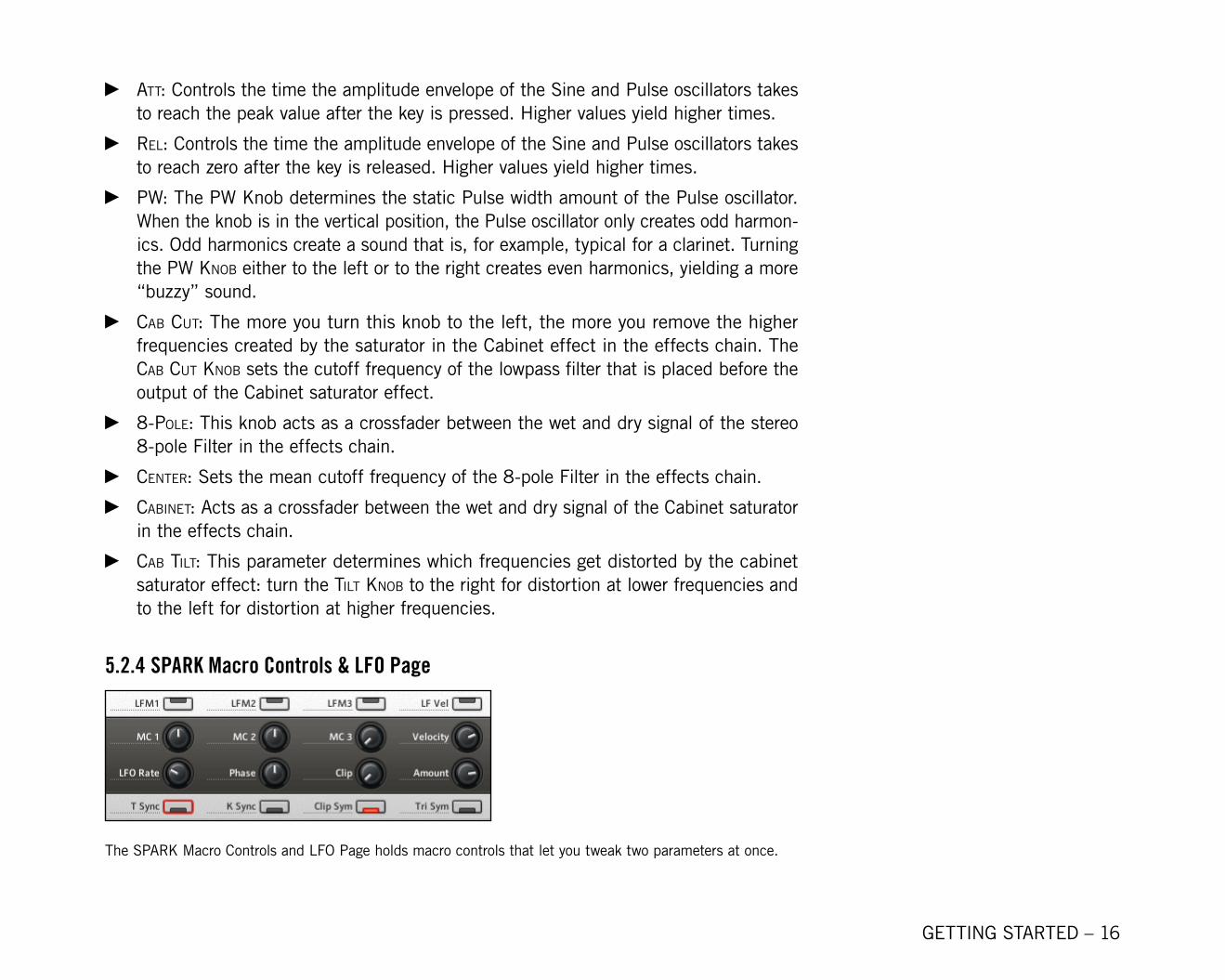
The SPARK Macro Controls and LFO Page holds macro controls that let you tweak two parameters at once.
►
►
►
►
►
►►
►
GETTING STARTED – 17
Mc 1: This knob controls the macro controller 1. Two parameters which are frequent-ly assigned to this controller are the amplitude of the oscillators and the input gain (drive) of the wave-shaper unit.
Mc 2: This knob controls the macro controller 2. Two parameters which are frequently assigned to this controller are the cutoff frequency and resonance of the internal filter.
Mc 3: This knob controls the macro controller 3. Two parameters which are frequent-ly assigned to this controller are the amount of signal feedback to the input of the Ringmod/Filters section and the dry/wet mix of the cabinet saturator unit.
velocity: When the lF vel Button is activated, this knob sets the center value around which the LFO modulates the velocity parameter of the instrument.
lFo rate: The macro controllers can be controlled by an LFO if the lFM Button (see below) is turned on for that particular controller. The lFo rate knoB sets the fre-quency of the LFO.
PhaSe: Determines the phase of the LFO. Read about the t Sync and k Sync Parameters below for more information on the effect of the PhaSe knoB.
cliP: Sets the amount of clipping to the LFO signal.
aMount: Determines the amplitude of the LFO and with it the amount of modulation to the macro controller parameters.
lFM1: If activated, the macro controller 1 parameter is modulated by the LFO.
lFM2: If activated, the macro controller 2 parameter is modulated by the LFO.
lFM3: If activated, the macro controller 3 parameter is modulated by the LFO.
lF vel: The velocity events received from the keyboard or sequencer are overridden if the lF vel Button is on and replaced by the LFO modulated value set by the velocity knoB.
t Sync: If activated, the LFO is synchronized to the global tempo assigned determined by KORE. If the t Sync Button is activated and the k Sync Button deactivated, the LFO phase is also synchronized with the song position. The phase of the LFO at the beginning of the song is set by the PhaSe knoB.
k Sync: With k Sync activated, the LFO is restarted every time a note is played. The phase at which the LFO restarts is set by the PhaSe knoB.
►
►
►
►
►
►
►►
►►►►
►
►
! The particular effect of the macro controllers differs between KORE
SOUNDS, as the instrument parameters which they have been assigned to were carefully chosen by the sound designer to suit the particular KORE SOUND.
! The particular effect of the macro controllers differs between KORE
SOUNDS, as the instrument parameters which they have been assigned to were carefully chosen by the sound designer to suit the particular KORE SOUND.
GETTING STARTED – 18
cliP SyM: With cliP SyM deactivated, only the bottom half of the LFO waveform is clipped. With the Clip Sym activated, only the top part of the LFO waveform is clipped. The amount of clipping is determined by the cliP knoB.
tri SyM: If deactivated, the LFO waveform is a symmetric triangle. With the tri SyM activated, the LFO waveform becomes a falling sawtooth.
5.3 Using SPARK in REAKTOR
In this section we will discuss how to make the best use of SPARK’s control panel within REAKTOR. It is exactly because of SPARK’s unconventional signal routing that SPARK achieves its expressive sonic character. Not only SPARK’s sonic capabilities set it apart from other more conventional synthesizers, but also the way it is used. To help you get fa-miliar with the behaviour of SPARK’s controls, we will briefly discuss the signal flow within the ensemble and then proceed to demonstrate the most prominent aspects of SPARK in a step-by-step tutorial.
5.3.1 Signal FlowSPARK’s control panel features the access to parameters that cannot be intuitively under-stood without knowledge of the signal flow. According to the figure on the following page, we will go through the main aspects of SPARK’s signal flow. The names of the different parts of the signal flow that directly correspond to the labels in the control panel are capi-talized and given the name sections.
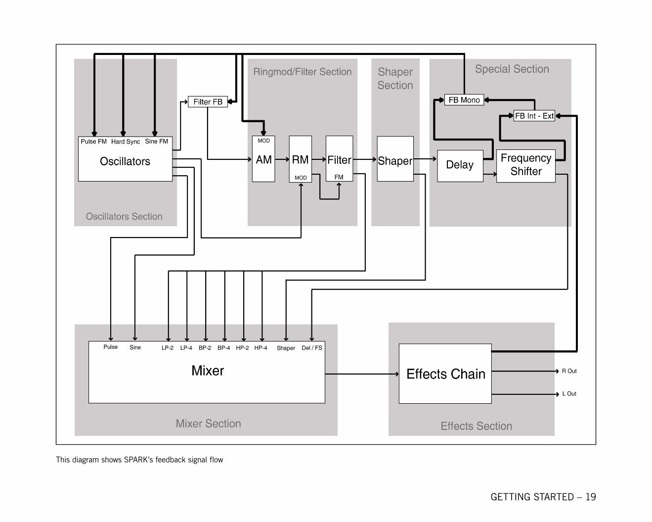
The sound generation in the instrument happens by two oscillators, Pulse and Sine, in the Oscillators section. Here we see how the output of two simple oscillators is more than just simple static waveforms: SPARK’s signal routing makes it possible to create complex and evolving waveforms by letting the feedback signal control both oscillators by frequency modulation and/or the Pulse oscillator by hard synchronization. In the figure on the next page, the bold lines illustrate the path of the feedback signal.
►
►
GETTING STARTED – 19
This diagram shows SPARK’s feedback signal flow
GETTING STARTED – 20
The output of the Oscillators section is the mixed with the feedback signal by the crossfader marked as “Filter FB” and fed as the carrier signal to an amplitude modulator, the first element in the Ringmod/Filters section. Again, the modulating signal again is the feedback signal. Amplitude modulation reduces the presence of the carrier signal harmonics, but adds the harmonics of the modulation signal into the mix in a more complex manner than just adding the two signals together.
The amplitude modulated signal is then ring modulated by the output of the Oscillators section. Ring modulation causes the harmonics to be mixed in a manner similar to am-plitude modulation with the difference that the harmonics of the incoming signals are not left intact. This often causes inharmonic spectra. The signal from the ring modulator is then fed to the filter, and subsequently to the shaper.
The voice delay in the Special section is a key element in the creating the feedback signal, it determines which frequencies are excited in the feedback loop. The frequency shifter is the last structure that allows direct manipulation of the frequency content of the spectra.
In the Mixer section, the signals from different points along the described path can be tapped and mixed together to be processed by the Effects section. The effects are always running and the degree that the output of the Mixer section is processed by a certain ef-fect unit is controlled by the unit´s Mix knoB.
The feedback signal is put together in the SPecial Section using the “FB Mono” and “Int – Ext” crossfaders, where turning the knobs to the right increasingly crossfades to the sig-nal that is represented on the right side of the crossfader in the figure. By now it is fairly obvious that the sound that reaches the instrument output at the end of the effects chain can have a wide range of timbres and evolving behaviours made possible by manipulating the feedback loop. Even with good knowledge of the signal flow the effects of changing the parameters can often be quite surprising, but that is also part of the fun when explor-ing SPARK’s capabilities.
GETTING STARTED – 21
5.3.2 TutorialIn this tutorial we will use a sound from the REAKTOR SPARK SOUNDPACK and manipu-late it using the SPARK control panel with the goal to create a new sound with certain characteristics. We want to make use of some of the special qualities of SPARK and for that reason we will opt for two main characteristics: first, the sound should exhibit a full, warm character that responds to the way notes are played and second, we want to imple-ment SPARK’s feedback loop to create interesting self-oscillating ripples that accompany the sound. The sound should have a definite pitch and have behaviour predictable enough that melodies can be played with it at both slow and fast speeds.
The universal Value Display in the SPARK Ensemble
To see the exact values of the currently handled controller, use the orange value diSPlay located above the Cabinet saturator unit. If you just want to check what value a controller has, click on it, and press the up or down arrow key on your keyboard. The value of that controller will appear in the universal value diSPlay.
To start off, we load the Kore Sound “Paddikk” by Denis Gökdag. Play around with the sound a bit and note the slow attack time and the periodic chorus-like effect induced by the LFO. For further playback of the sound during this tutorial we will stick to the MIDI note C4 (MIDI value 72), as the timbre of the sound can significantly differ in different registers.
First, we remember that instead of a slow evolving pad we are looking for synth lead type of sound, and we shouldn’t have to wait after pressing the key to hear the sound. We see that the amplitude envelope in the Oscillators section shows a long attack time. We turn the knob with the label a to the value -� and hear that playing a note will yield a sound right away.
GETTING STARTED – 22
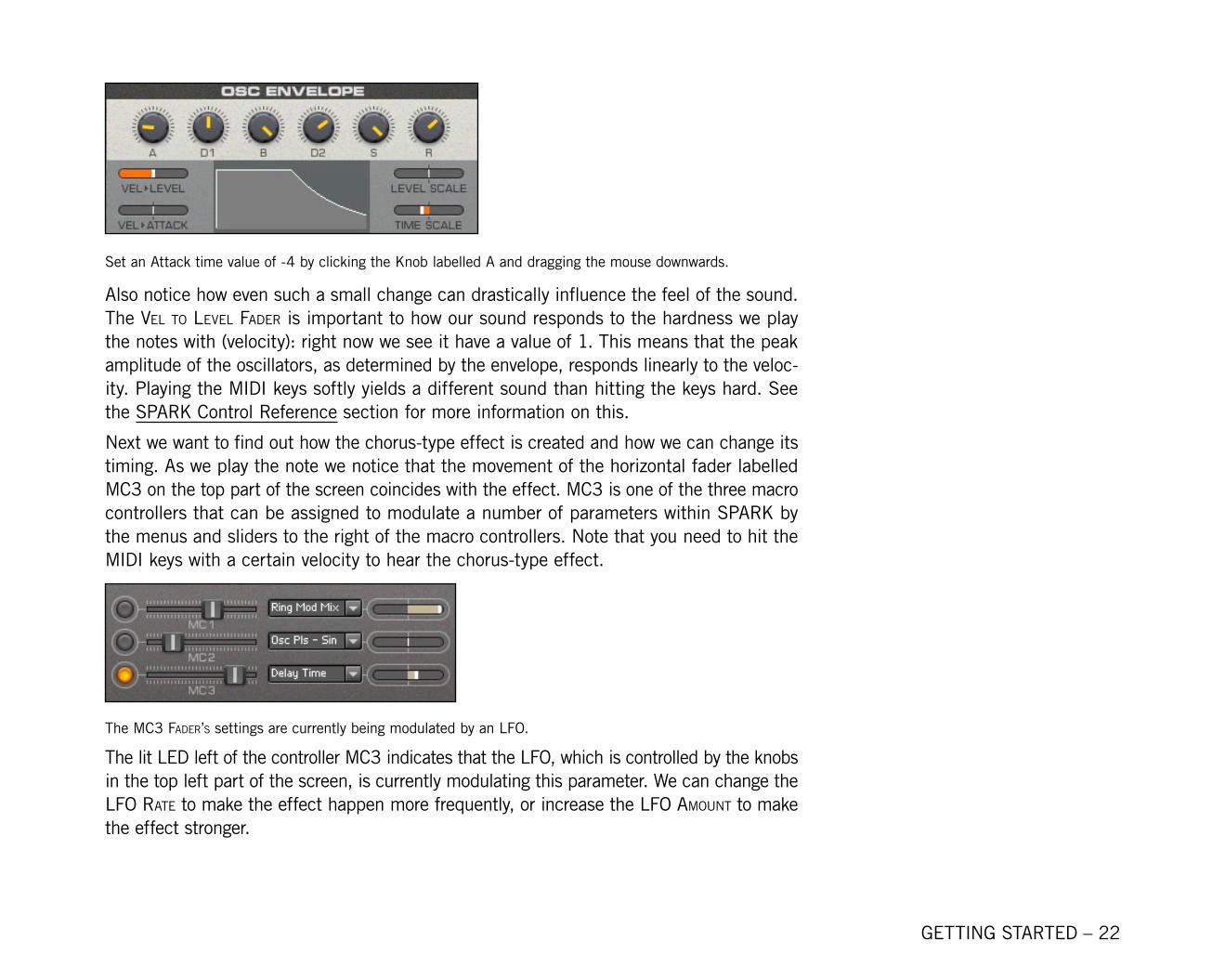
Set an Attack time value of -� by clicking the Knob labelled A and dragging the mouse downwards.
Also notice how even such a small change can drastically influence the feel of the sound. The vel to level Fader is important to how our sound responds to the hardness we play the notes with (velocity): right now we see it have a value of 1. This means that the peak amplitude of the oscillators, as determined by the envelope, responds linearly to the veloc-ity. Playing the MIDI keys softly yields a different sound than hitting the keys hard. See the SPARK Control Reference section for more information on this.
Next we want to find out how the chorus-type effect is created and how we can change its timing. As we play the note we notice that the movement of the horizontal fader labelled Mc3 on the top part of the screen coincides with the effect. Mc3 is one of the three macro controllers that can be assigned to modulate a number of parameters within SPARK by the menus and sliders to the right of the macro controllers. Note that you need to hit the MIDI keys with a certain velocity to hear the chorus-type effect.
The Mc3 Fader’S settings are currently being modulated by an LFO.
The lit LED left of the controller Mc3 indicates that the LFO, which is controlled by the knobs in the top left part of the screen, is currently modulating this parameter. We can change the lFo rate to make the effect happen more frequently, or increase the lFo aMount to make the effect stronger.
GETTING STARTED – 23
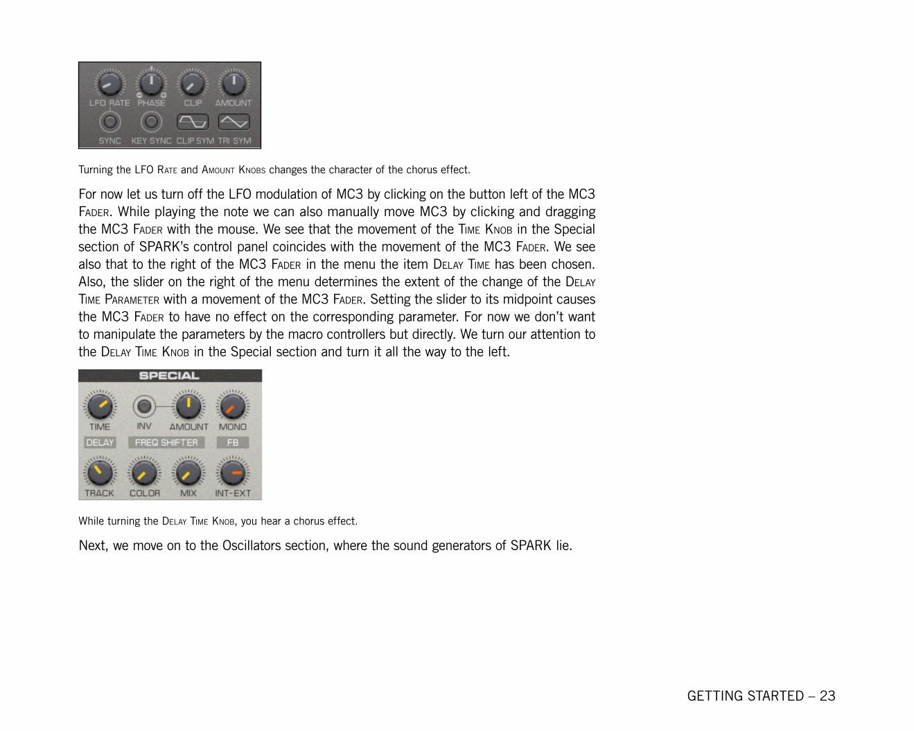
Turning the lFo rate and aMount knoBS changes the character of the chorus effect.
For now let us turn off the LFO modulation of Mc3 by clicking on the button left of the Mc3 Fader. While playing the note we can also manually move Mc3 by clicking and dragging the Mc3 Fader with the mouse. We see that the movement of the tiMe knoB in the Special section of SPARK’s control panel coincides with the movement of the Mc3 Fader. We see also that to the right of the Mc3 Fader in the menu the item delay tiMe has been chosen. Also, the slider on the right of the menu determines the extent of the change of the delay tiMe ParaMeter with a movement of the Mc3 Fader. Setting the slider to its midpoint causes the Mc3 Fader to have no effect on the corresponding parameter. For now we don’t want to manipulate the parameters by the macro controllers but directly. We turn our attention to the delay tiMe knoB in the Special section and turn it all the way to the left.
While turning the delay tiMe knoB, you hear a chorus effect.
Next, we move on to the Oscillators section, where the sound generators of SPARK lie.
GETTING STARTED – 2�
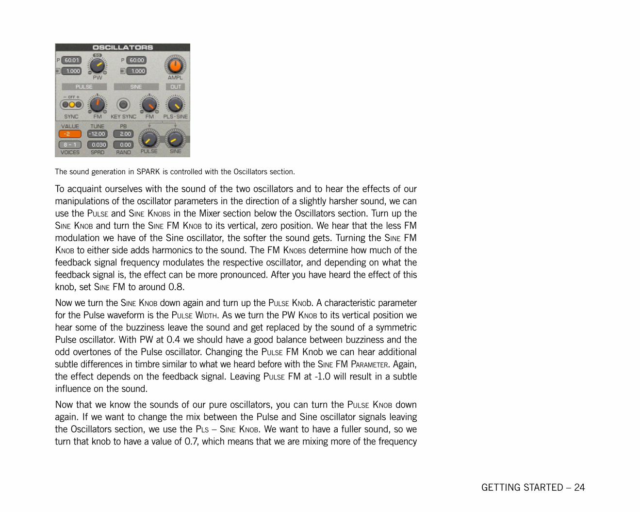
The sound generation in SPARK is controlled with the Oscillators section.
To acquaint ourselves with the sound of the two oscillators and to hear the effects of our manipulations of the oscillator parameters in the direction of a slightly harsher sound, we can use the PulSe and Sine knoBS in the Mixer section below the Oscillators section. Turn up the Sine knoB and turn the Sine FM knoB to its vertical, zero position. We hear that the less FM modulation we have of the Sine oscillator, the softer the sound gets. Turning the Sine FM knoB to either side adds harmonics to the sound. The FM knoBS determine how much of the feedback signal frequency modulates the respective oscillator, and depending on what the feedback signal is, the effect can be more pronounced. After you have heard the effect of this knob, set Sine FM to around 0.8.
Now we turn the Sine knoB down again and turn up the PulSe knob. A characteristic parameter for the Pulse waveform is the PulSe Width. As we turn the PW knoB to its vertical position we hear some of the buzziness leave the sound and get replaced by the sound of a symmetric Pulse oscillator. With PW at 0.� we should have a good balance between buzziness and the odd overtones of the Pulse oscillator. Changing the PulSe FM Knob we can hear additional subtle differences in timbre similar to what we heard before with the Sine FM ParaMeter. Again, the effect depends on the feedback signal. Leaving PulSe FM at -1.0 will result in a subtle influence on the sound.
Now that we know the sounds of our pure oscillators, you can turn the PulSe knoB down again. If we want to change the mix between the Pulse and Sine oscillator signals leaving the Oscillators section, we use the PlS – Sine knoB. We want to have a fuller sound, so we turn that knob to have a value of 0.7, which means that we are mixing more of the frequency
GETTING STARTED – 25
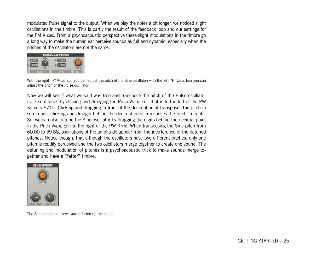
modulated Pulse signal to the output. When we play the notes a bit longer, we noticed slight oscillations in the timbre. This is partly the result of the feedback loop and our settings for the FM knoBS. From a psychoacoustic perspective these slight modulations in the timbre go a long way to make the human ear perceive sounds as full and dynamic, especially when the pitches of the oscillators are not the same.
With the right ‘P’ value edit you can adjust the pitch of the Sine oscillator; with the left ‘P’ value edit you can adjust the pitch of the Pulse oscillator.
Now we will see if what we said was true and transpose the pitch of the Pulse oscillator up 7 semitones by clicking and dragging the Pitch value edit that is to the left of the PW knoB to 67.01. Clicking and dragging in front of the decimal point transposes the pitch in. Clicking and dragging in front of the decimal point transposes the pitch in semitones, clicking and draggin behind the decimal point transposes the pitch in cents. So, we can also detune the Sine oscillator by dragging the digits behind the decimal point in the Pitch value edit to the right of the PW knoB. When transposing the Sine pitch from 60.00 to 59.88, oscillations of the amplitude appear from the interference of the detuned pitches. Notice though, that although the oscillators have two different pitches, only one pitch is readily perceived and the two oscillators merge together to create one sound. The detuning and modulation of pitches is a psychoacoustic trick to make sounds merge to-gether and have a “fatter” timbre.
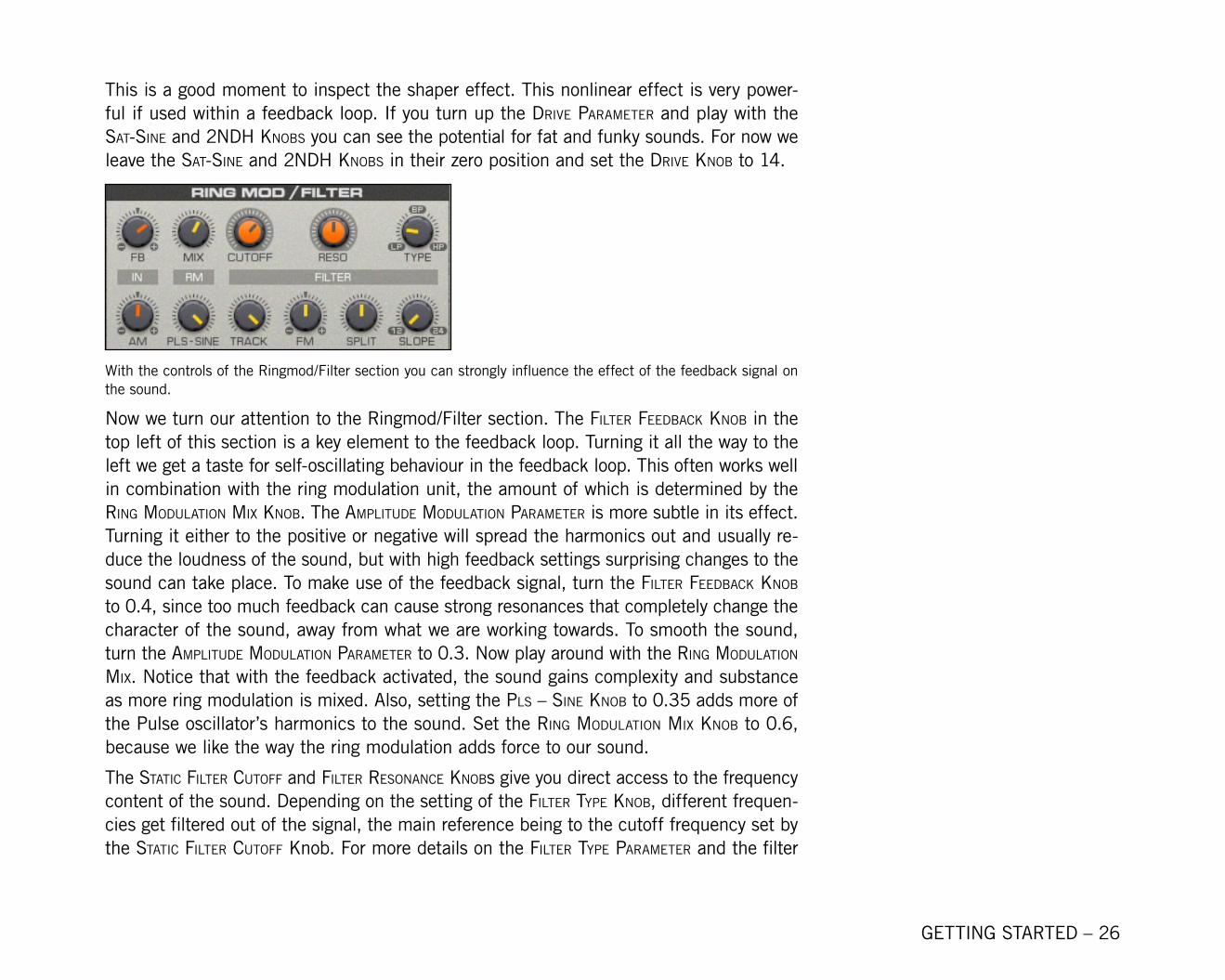
The Shaper section allows you to fatten up the sound.
GETTING STARTED – 26
This is a good moment to inspect the shaper effect. This nonlinear effect is very power-ful if used within a feedback loop. If you turn up the drive ParaMeter and play with the Sat-Sine and 2ndh knoBS you can see the potential for fat and funky sounds. For now we leave the Sat-Sine and 2ndh knoBS in their zero position and set the drive knoB to 1�.
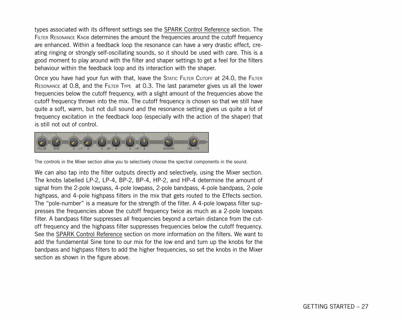
With the controls of the Ringmod/Filter section you can strongly influence the effect of the feedback signal on the sound.
Now we turn our attention to the Ringmod/Filter section. The Filter FeedBack knoB in the top left of this section is a key element to the feedback loop. Turning it all the way to the left we get a taste for self-oscillating behaviour in the feedback loop. This often works well in combination with the ring modulation unit, the amount of which is determined by the ring Modulation Mix knoB. The aMPlitude Modulation ParaMeter is more subtle in its effect. Turning it either to the positive or negative will spread the harmonics out and usually re-duce the loudness of the sound, but with high feedback settings surprising changes to the sound can take place. To make use of the feedback signal, turn the Filter FeedBack knoB to 0.�, since too much feedback can cause strong resonances that completely change the character of the sound, away from what we are working towards. To smooth the sound, turn the aMPlitude Modulation ParaMeter to 0.3. Now play around with the ring Modulation Mix. Notice that with the feedback activated, the sound gains complexity and substance as more ring modulation is mixed. Also, setting the PlS – Sine knoB to 0.35 adds more of the Pulse oscillator’s harmonics to the sound. Set the ring Modulation Mix knoB to 0.6, because we like the way the ring modulation adds force to our sound.
The Static Filter cutoFF and Filter reSonance knoBs give you direct access to the frequency content of the sound. Depending on the setting of the Filter tyPe knoB, different frequen-cies get filtered out of the signal, the main reference being to the cutoff frequency set by the Static Filter cutoFF Knob. For more details on the Filter tyPe ParaMeter and the filter
GETTING STARTED – 27
types associated with its different settings see the SPARK Control Reference section. The Filter reSonance knoB determines the amount the frequencies around the cutoff frequency are enhanced. Within a feedback loop the resonance can have a very drastic effect, cre-ating ringing or strongly self-oscillating sounds, so it should be used with care. This is a good moment to play around with the filter and shaper settings to get a feel for the filters behaviour within the feedback loop and its interaction with the shaper.
Once you have had your fun with that, leave the Static Filter cutoFF at 2�.0, the Filter reSonance at 0.8, and the Filter tyPe at 0.3. The last parameter gives us all the lower frequencies below the cutoff frequency, with a slight amount of the frequencies above the cutoff frequency thrown into the mix. The cutoff frequency is chosen so that we still have quite a soft, warm, but not dull sound and the resonance setting gives us quite a lot of frequency excitation in the feedback loop (especially with the action of the shaper) that is still not out of control.
The controls in the Mixer section allow you to selectively choose the spectral components in the sound.
We can also tap into the filter outputs directly and selectively, using the Mixer section. The knobs labelled lP-2, lP-4, BP-2, BP-4, hP-2, and hP-4 determine the amount of signal from the 2-pole lowpass, �-pole lowpass, 2-pole bandpass, �-pole bandpass, 2-pole highpass, and 4-pole highpass filters in the mix that gets routed to the Effects section. The “pole-number” is a measure for the strength of the filter. A 4-pole lowpass filter sup-presses the frequencies above the cutoff frequency twice as much as a 2-pole lowpass filter. A bandpass filter suppresses all frequencies beyond a certain distance from the cut-off frequency and the highpass filter suppresses frequencies below the cutoff frequency. See the SPARK Control Reference section on more information on the filters. We want to add the fundamental Sine tone to our mix for the low end and turn up the knobs for the bandpass and highpass filters to add the higher frequencies, so set the knobs in the Mixer section as shown in the figure above.
GETTING STARTED – 28
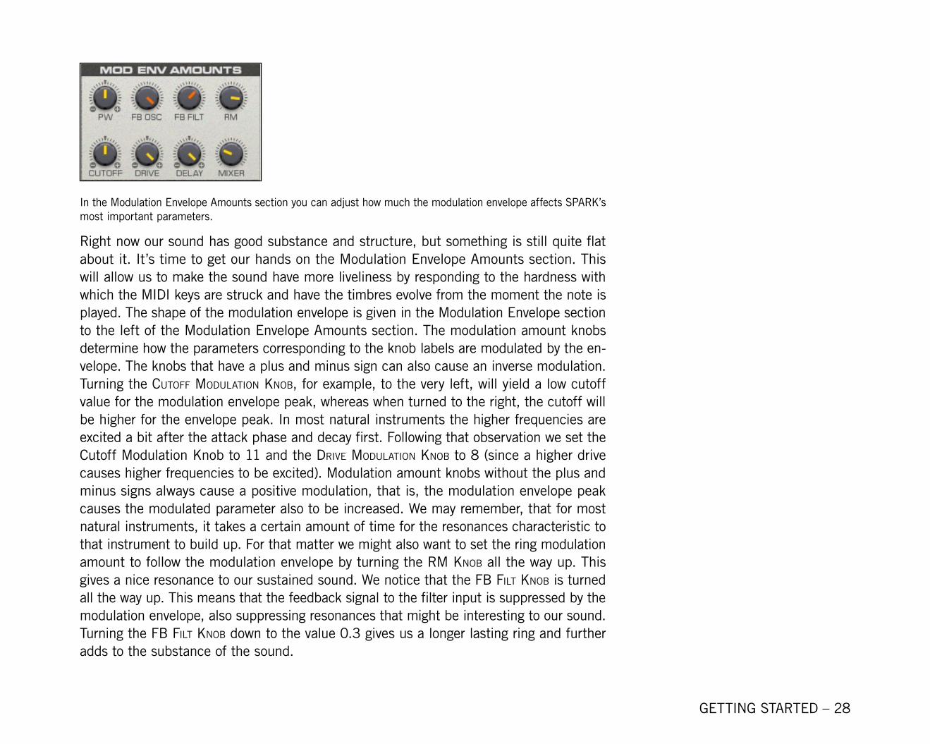
In the Modulation Envelope Amounts section you can adjust how much the modulation envelope affects SPARK’s most important parameters.
Right now our sound has good substance and structure, but something is still quite flat about it. It’s time to get our hands on the Modulation Envelope Amounts section. This will allow us to make the sound have more liveliness by responding to the hardness with which the MIDI keys are struck and have the timbres evolve from the moment the note is played. The shape of the modulation envelope is given in the Modulation Envelope section to the left of the Modulation Envelope Amounts section. The modulation amount knobs determine how the parameters corresponding to the knob labels are modulated by the en-velope. The knobs that have a plus and minus sign can also cause an inverse modulation. Turning the cutoFF Modulation knoB, for example, to the very left, will yield a low cutoff value for the modulation envelope peak, whereas when turned to the right, the cutoff will be higher for the envelope peak. In most natural instruments the higher frequencies are excited a bit after the attack phase and decay first. Following that observation we set the Cutoff Modulation Knob to 11 and the drive Modulation knoB to 8 (since a higher drive causes higher frequencies to be excited). Modulation amount knobs without the plus and minus signs always cause a positive modulation, that is, the modulation envelope peak causes the modulated parameter also to be increased. We may remember, that for most natural instruments, it takes a certain amount of time for the resonances characteristic to that instrument to build up. For that matter we might also want to set the ring modulation amount to follow the modulation envelope by turning the rM knoB all the way up. This gives a nice resonance to our sustained sound. We notice that the FB Filt knoB is turned all the way up. This means that the feedback signal to the filter input is suppressed by the modulation envelope, also suppressing resonances that might be interesting to our sound. Turning the FB Filt knoB down to the value 0.3 gives us a longer lasting ring and further adds to the substance of the sound.
GETTING STARTED – 29
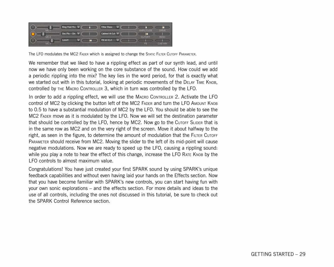
The LFO modulates the Mc2 Fader which is assigned to change the Static Filter cutoFF ParaMeter.
We remember that we liked to have a rippling effect as part of our synth lead, and until now we have only been working on the core substance of the sound. How could we add a periodic rippling into the mix? The key lies in the word period, for that is exactly what we started out with in this tutorial, looking at periodic movements of the delay tiMe knoB, controlled by the Macro controller 3, which in turn was controlled by the LFO.
In order to add a rippling effect, we will use the Macro controller 2. Activate the LFO control of Mc2 by clicking the button left of the Mc2 Fader and turn the lFo aMount knoB to 0.5 to have a substantial modulation of MC2 by the LFO. You should be able to see the Mc2 Fader move as it is modulated by the LFO. Now we will set the destination parameter that should be controlled by the LFO, hence by Mc2. Now go to the cutoFF Slider that is in the same row as Mc2 and on the very right of the screen. Move it about halfway to the right, as seen in the figure, to determine the amount of modulation that the Filter cutoFF ParaMeter should receive from Mc2. Moving the slider to the left of its mid-point will cause negative modulations. Now we are ready to speed up the LFO, causing a rippling sound: while you play a note to hear the effect of this change, increase the lFo rate knoB by the LFO controls to almost maximum value.
Congratulations! You have just created your first SPARK sound by using SPARK’s unique feedback capabilities and without even having laid your hands on the Effects section. Now that you have become familiar with SPARK’s new controls, you can start having fun with your own sonic explorations – and the effects section. For more details and ideas to the use of all controls, including the ones not discussed in this tutorial, be sure to check out the SPARK Control Reference section.
GETTING STARTED – 30
5.4 SPARK Control Reference
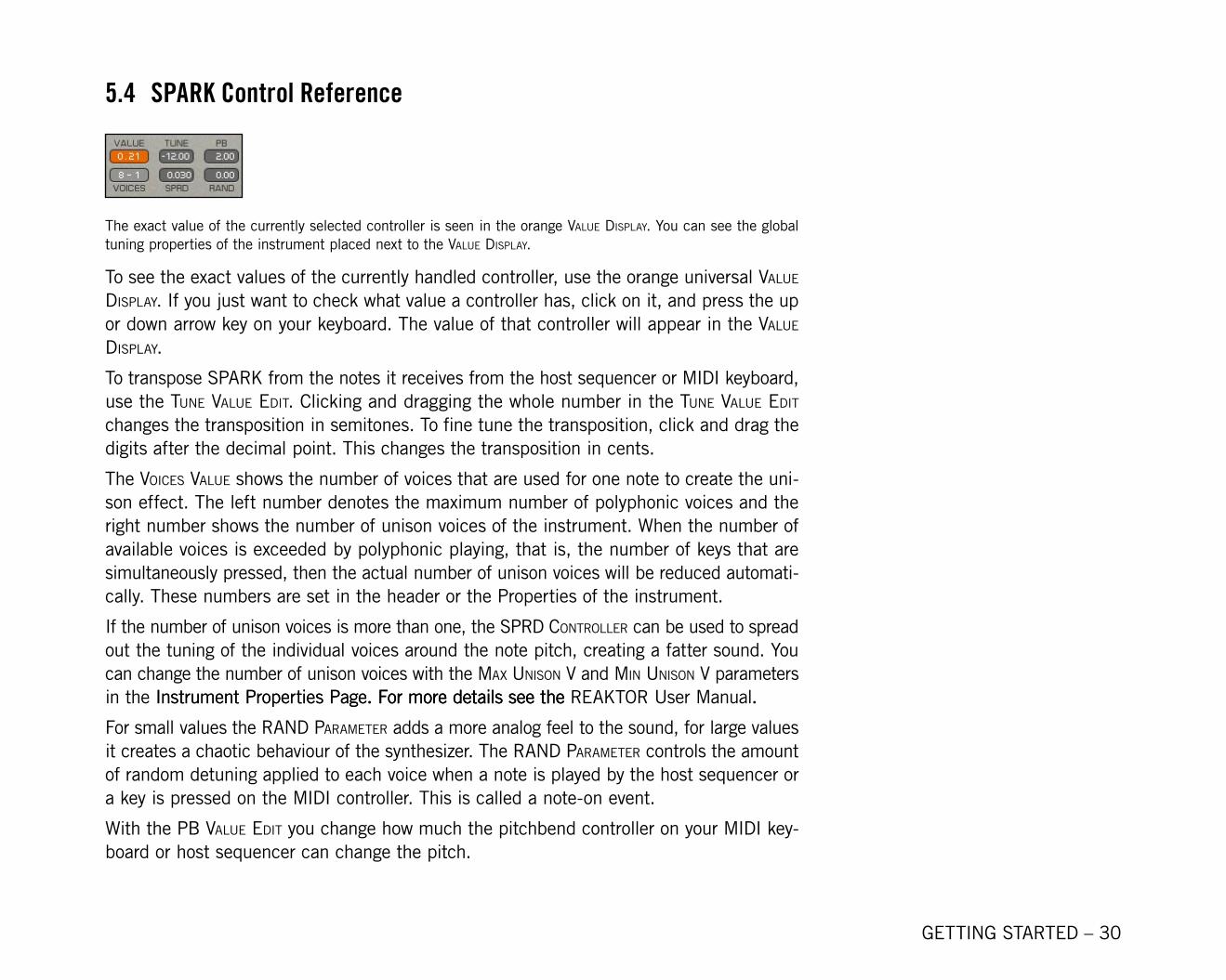
The exact value of the currently selected controller is seen in the orange value diSPlay. You can see the global tuning properties of the instrument placed next to the value diSPlay.
To see the exact values of the currently handled controller, use the orange universal value diSPlay. If you just want to check what value a controller has, click on it, and press the up or down arrow key on your keyboard. The value of that controller will appear in the value diSPlay.
To transpose SPARK from the notes it receives from the host sequencer or MIDI keyboard, use the tune value edit. Clicking and dragging the whole number in the tune value edit changes the transposition in semitones. To fine tune the transposition, click and drag the digits after the decimal point. This changes the transposition in cents.
The voiceS value shows the number of voices that are used for one note to create the uni-son effect. The left number denotes the maximum number of polyphonic voices and the right number shows the number of unison voices of the instrument. When the number of available voices is exceeded by polyphonic playing, that is, the number of keys that are simultaneously pressed, then the actual number of unison voices will be reduced automati-cally. These numbers are set in the header or the Properties of the instrument.
If the number of unison voices is more than one, the SPrd controller can be used to spread out the tuning of the individual voices around the note pitch, creating a fatter sound. You can change the number of unison voices with the Max uniSon v and Min uniSon v parameters in the Instrument Properties Page. For more details see the Instrument Properties Page. For more details see the. For more details see the REAKTOR User Manual..
For small values the rand ParaMeter adds a more analog feel to the sound, for large values it creates a chaotic behaviour of the synthesizer. The rand ParaMeter controls the amount of random detuning applied to each voice when a note is played by the host sequencer or a key is pressed on the MIDI controller. This is called a note-on event.
With the PB value edit you change how much the pitchbend controller on your MIDI key-board or host sequencer can change the pitch.
GETTING STARTED – 31
5.4.1 Oscillators Section
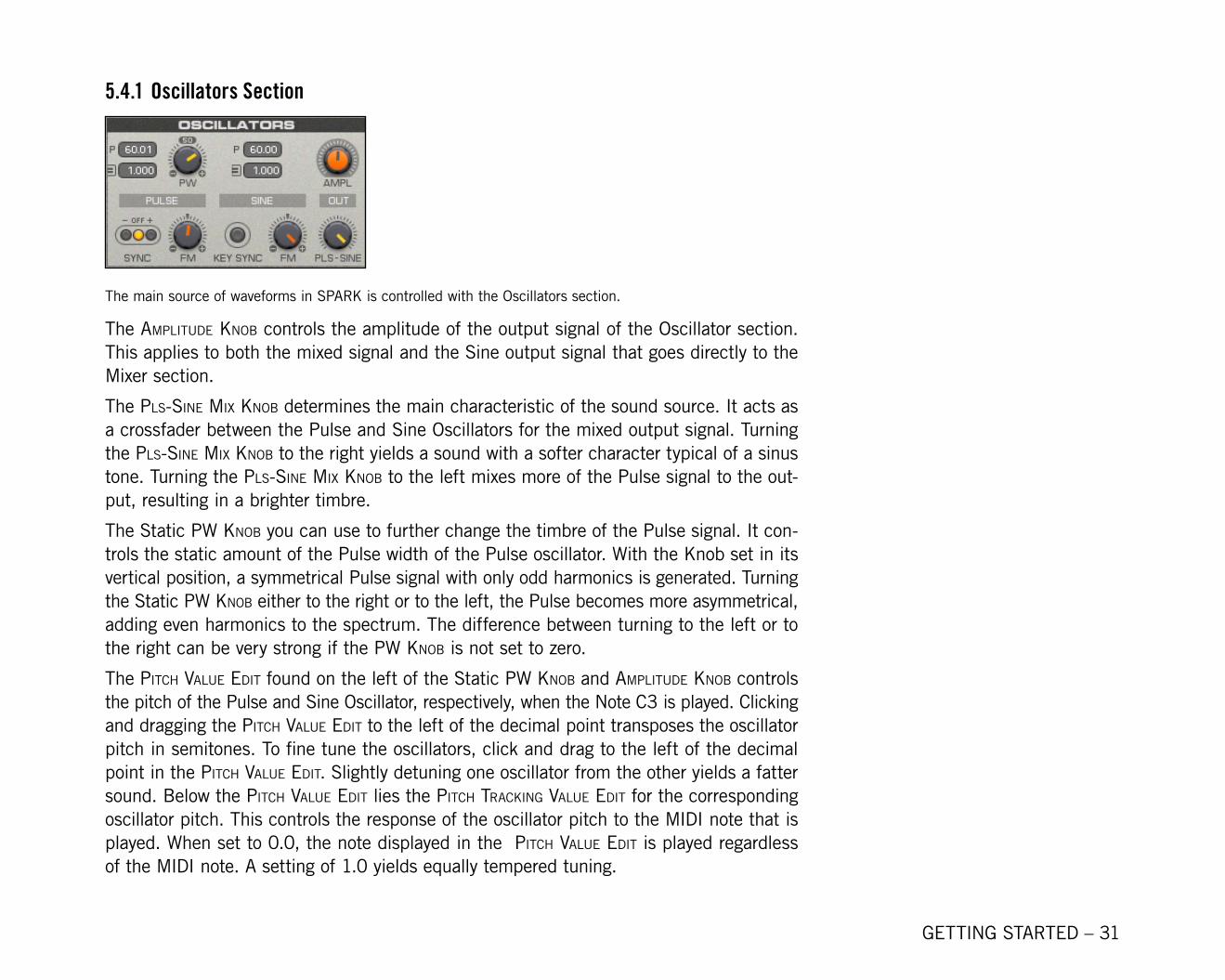
The main source of waveforms in SPARK is controlled with the Oscillators section.
The aMPlitude knoB controls the amplitude of the output signal of the Oscillator section. This applies to both the mixed signal and the Sine output signal that goes directly to the Mixer section.
The PlS-Sine Mix knoB determines the main characteristic of the sound source. It acts as a crossfader between the Pulse and Sine Oscillators for the mixed output signal. Turning the PlS-Sine Mix knoB to the right yields a sound with a softer character typical of a sinus tone. Turning the PlS-Sine Mix knoB to the left mixes more of the Pulse signal to the out-put, resulting in a brighter timbre.
The Static PW knoB you can use to further change the timbre of the Pulse signal. It con-trols the static amount of the Pulse width of the Pulse oscillator. With the Knob set in its vertical position, a symmetrical Pulse signal with only odd harmonics is generated. Turning the Static PW knoB either to the right or to the left, the Pulse becomes more asymmetrical, adding even harmonics to the spectrum. The difference between turning to the left or to the right can be very strong if the PW knoB is not set to zero.
The Pitch value edit found on the left of the Static PW knoB and aMPlitude knoB controls the pitch of the Pulse and Sine Oscillator, respectively, when the Note C3 is played. Clicking and dragging the Pitch value edit to the left of the decimal point transposes the oscillator pitch in semitones. To fine tune the oscillators, click and drag to the left of the decimal point in the Pitch value edit. Slightly detuning one oscillator from the other yields a fatter sound. Below the Pitch value edit lies the Pitch tracking value edit for the corresponding oscillator pitch. This controls the response of the oscillator pitch to the MIDI note that is played. When set to 0.0, the note displayed in the Pitch value edit is played regardless of the MIDI note. A setting of 1.0 yields equally tempered tuning.
GETTING STARTED – 32
In order to make the sinus signal have a brighter character, the Sine FM knoB is used. It sets the amount of frequency modulation of the Sine Oscillator by the feedback signal. When the PlS – Sine Mix knoB is completely set to Sine, setting the Sine FM knoB to a nonzero value results in a kind of sawtooth sound.
Similarly, nonzero settings of the PulSe FM knoB can strongly alter the character wave-form of the signal exiting the Pulse Oscillator. The PulSe FM knoB controls the amount of frequency modulation of the Pulse Oscillator by the feedback signal.
The key Sync Button is a parameter that determines the reproducabilty of sounds when the same notes are successively played. With the key Sync Button turned on, the Sine and Pulse Oscillators restart at zero with each note-on event received from the MIDI keyboard or host sequencer. See rand ParaMeter for a description of the note-on event.
Setting the Sync Button to + or – often leads to chaotic behaviour, sometimes with pitchleads to chaotic behaviour, sometimes with pitch drifting or a crackling timbre. The Sync Button activates the hard sync of the Pulse Oscillator, restarting the waveform with each zero crossing of the feedback signal. The Sync Button settings + and - restart the Pulse with positive or negative zero crossings of the feedback signal, respectively. The setting of the PW knoB has a strong influence on the effect of the hard synchronization. With the Sync Button in the oFF position, the Pulse Oscillator can be synced to note-on events if the key Sync Button is in the on position. See rand ParaMeter for a description of the note-on event.
5.4.2 Ring Mod/Filter Section
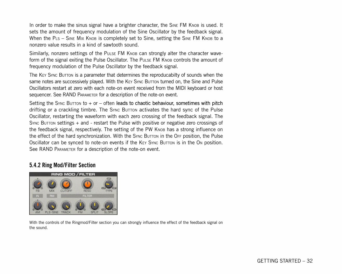
With the controls of the Ringmod/Filter section you can strongly influence the effect of the feedback signal on the sound.
GETTING STARTED – 33
One can very drastically change the character of the sound by turning thethe Filter FB knoB control only slightly. The result can be self-oscillating sounds with a pitch that is only dependent on the cutoff frequency of the filter, or sounds resembling acoustic feedbacks of microphones, speakers, or guitar amps. The Filter FB knoB controls the amount of feedback signal mixed to the Oscillator section output before it gets routed to the Ring Mod/Filter section.
The aM knoB enables you to add additional harmonics to the signal from the Oscillators section entering the Ring Modulator. This parameter usually has a subtle effect. With thehe aM knoB you control the amount of amplitude modulation applied to the mixed outputs of the Oscillators section and the feedback signal. The mixed output is amplitude modulated by the feedback signal.
With the rM Mix knoB you can change the characteristic of the sound by adding inhar-monic components to the signal. This parameter determines the amount of ring modulation the amplitude modulated signal receives. The modulating signal comes directly from the Oscillators section.
The source signal for the ring modulator is controlled by the RM PlS-Sine knoB. Turning the knob to the left yields a harsher sound, turning it to the right a softer sound. The RM PlS-Sine knoB determines how much of the modulating signal comes from the Pulse Oscillator and how much from the Sine Oscillator. The modulating signal from the Oscillators section is not affected by the Oscillator Envelope.
The Static cutoFF knoB is a main parameter of the Filter section. It determines which fre-quencies are filtered out of the signal and which ones are passed on to the output of this section. The Static cutoFF knoB is used as a reference value for the cutoff frequency of both parts of the multi-mode filter. The difference between the cutoff frequencies of the two filters is controlled by the SPlit knoB.
Filters not only filter out frequencies, but also enhance others. The reSonance knoB controls the amount of resonance of both filters, that is, the amount of the signal enhancement at cutoff frequency. High values yield a sound that resembles a sinus tone.
Depending on the setting of the Filter tyPe knoB, one can filter out different frequencies in relation to the cutoff frequency. A lowpass filter (LP) lets frequencies below the cutoff frequency pass, a highpass filter (HP) lets frequencies above the cutoff frequency pass,
GETTING STARTED – 3�
and a bandpass filter (BP) lets frequencies within a certain distance from the cutoff fre-quency pass. The setting of the Filter tyPe knoB determines the type for both filters.
The Filter SloPe knoB controls how much the frequencies outside of the filter’s “pass”-in-terval are damped before the signal is passed to the Shaper section. Turn the Filter SloPe knoB to the left for weaker filtering, to the right for stronger filtering. The Filter section consists of two serially connected filters, each damping 12 dB/octave. The Filter SloPe knoB determines if the output signal of only one or both filters is used for the Shaper sec-tion input.
The Filter track knoB sets the tracking amount of the filter cutoffs. Since digital instru-ments seem to sound too bright when notes in the higher registers are played, using the Filter track knoB helps you counteract that so the cutoff frequency of the filter depends on the note that is played. When the Filter track knoB set to 0.0, no tracking with the key position takes place, and when set to 1.0, the key position relative to C3 is fully added to the filter cutoff. For sounds that don’t exhibit an excessively bright timbre in the upper registers, turn the Filter track knoB to a value between 0.0 and 1.0.
The color of the Filter section’s output signal can be further controlled with the Filter FM knoB. This parameter controls how much the filter cutoff frequency is modulated by the filter input signal.
5.4.3 Shaper Section
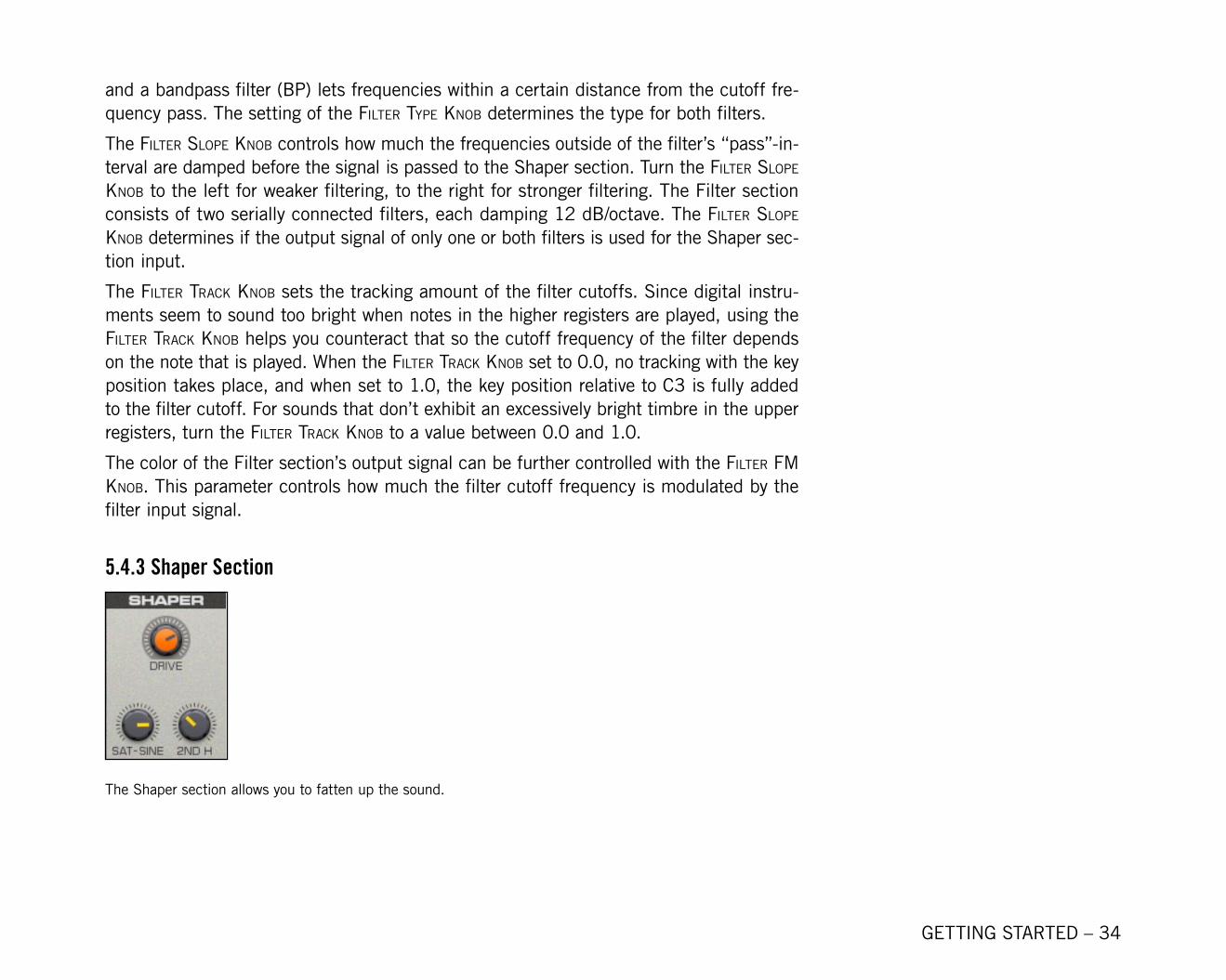
The Shaper section allows you to fatten up the sound.
GETTING STARTED – 35
Wave-shaping adds interesting amplitude-dependent sound colors. The amount of distortion and harmonics added to the signal is controlled by the Shaper drive knoB. It determines the input gain of the Shaper section.
The Sat - Sine knoB lets you crossfade between two characteristic sounds resulting from two wave-shaping curves: a parabolic saturation curve and a Sine curve, which folds back the waveform of larger signals.
Similarly, the 2ndh knoB lets you change the harmonic content of the signal resulting from the wave-shaping. At zero the shaping curves are symmetric, creating mainly odd harmon-ics. With larger values the curve gets increasingly asymmetric and the amount of the 2nd and other even harmonics is increased.
5.4.4 Special Section
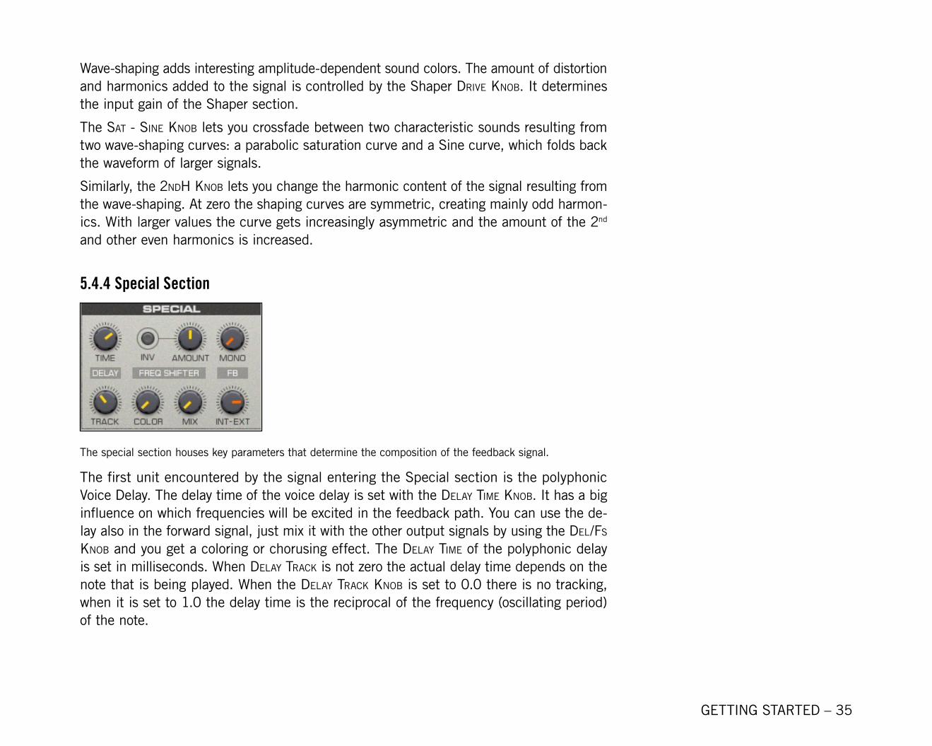
The special section houses key parameters that determine the composition of the feedback signal.
The first unit encountered by the signal entering the Special section is the polyphonic Voice Delay. The delay time of the voice delay is set with the delay tiMe knoB. It has a big influence on which frequencies will be excited in the feedback path. You can use the de-lay also in the forward signal, just mix it with the other output signals by using the del/FS knoB and you get a coloring or chorusing effect. The delay tiMe of the polyphonic delay is set in milliseconds. When delay track is not zero the actual delay time depends on the note that is being played. When the delay track knoB is set to 0.0 there is no tracking, when it is set to 1.0 the delay time is the reciprocal of the frequency (oscillating period) of the note.
GETTING STARTED – 36
The FreQuency ShiFt aMount knoB causes all frequencies entering the Frequency Shifter unit to be changed by that amount. This usually results in an inharmonic or phasing sound. Depending on the setting of the FreQuency ShiFt aMount knoB the frequencies get shifted by 0.2 Hz to 10000Hz. If the neg Button is in the on position, the frequencies get shifted down instead of up. Negative frequencies resulting from the shift get mirrored back into the positive spectrum. The color knoB adjusts the internal feedback signal, higher values create higher harmonics and stronger phasing effects. Use this to brighten up the sound at higher shift frequencies or to create a stronger phasing effect at lower shift frequencies. The FreQuency ShiFter Mix knoB controls the amount of frequency shifted (wet) signal mixed to the non-frequency shifted (dry) signal before it gets sent to the output of this unit.
The FB Mono and FB Int - Ext knoBS are key parameters controlling the mix of the feed-back signal. The FB Mono knoB acts as a crossfader between the polyphonic Delay unit’s output and the monophonic signal mixed together from the Frequency Shifter unit’s output and the output of the Effects section. The mix of the monophonic signal is determined by the FB Int - Ext knoB. Here possibilities arise for very interesting effects like cross-talk between the individual voices. This arises when a nonzero setting of the FB Mono knoB causes the monophonic feedback signal to be distributed among all the voices of the polyphonic feedback signal.
5.4.5 Mixer Section
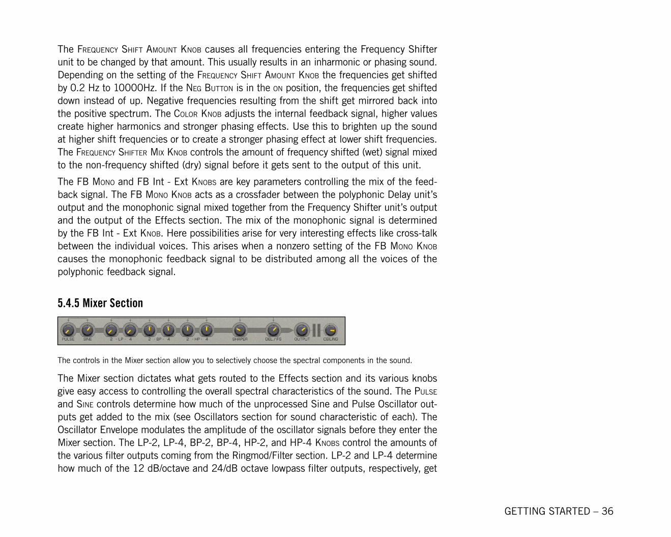
The controls in the Mixer section allow you to selectively choose the spectral components in the sound.
The Mixer section dictates what gets routed to the Effects section and its various knobs give easy access to controlling the overall spectral characteristics of the sound. The PulSe and Sine controls determine how much of the unprocessed Sine and Pulse Oscillator out-puts get added to the mix (see Oscillators section for sound characteristic of each). The Oscillator Envelope modulates the amplitude of the oscillator signals before they enter the Mixer section. The lP-2, lP-4, BP-2, BP-4, hP-2, and hP-4 knoBS control the amounts of the various filter outputs coming from the Ringmod/Filter section. lP-2 and LP-� determine how much of the 12 dB/octave and 24/dB octave lowpass filter outputs, respectively, get
GETTING STARTED – 37
mixed to the Effects section’s input. The same applies for the BP-2 and BP-4, hP-2 and HP-4 knoBS, where BP stands for the bandpass and HP stands for high the pass filter. Similar to the filter controls in the Mixer section, the ShaPer knoB controls the amount of the Shaper unit’s output signal, and the del/FS knoB controls the amount of the Frequency Shifter unit’s output signal entering the Effects section. The outPut controller determines the overall signal level sent from the Mixer section to the Effects section. The left level Meter in the output unit shows the level behind the outPut controller.
The ceiling knoB is used to control the maximum output level of SPARK. The ceiling knoB should be set a bit below 0 dB to prevent clipping at the soundcard. It functions as a control for the signal level that comes from the ouput of the limiter unit placed behind the Effects section. The right level Meter in the output unit shows the amount that the synthesizer output signal is reduced by the limiter.
5.4.6 Cabinet Section
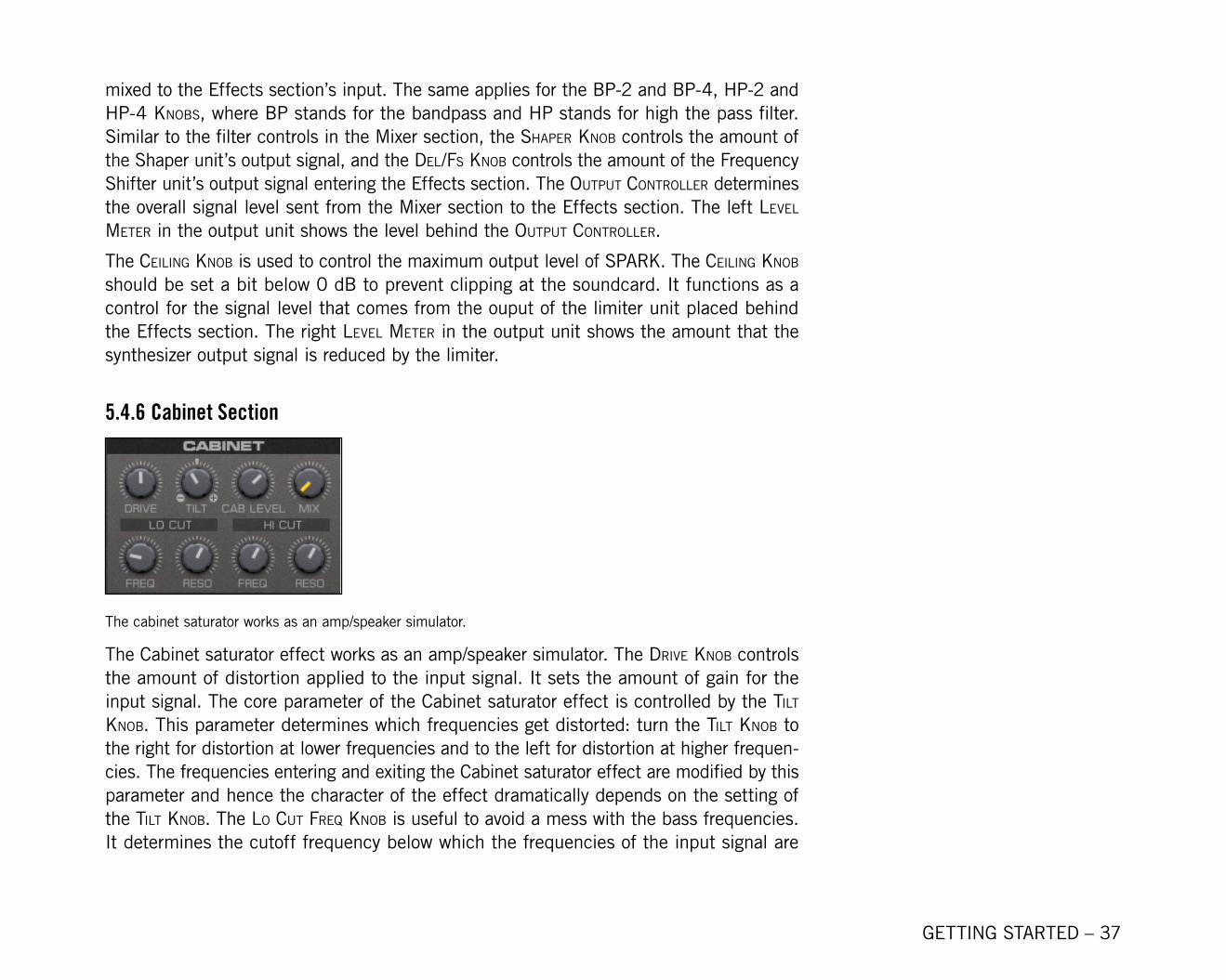
The cabinet saturator works as an amp/speaker simulator.
The Cabinet saturator effect works as an amp/speaker simulator. The drive knoB controls the amount of distortion applied to the input signal. It sets the amount of gain for the input signal. The core parameter of the Cabinet saturator effect is controlled by the tilt knoB. This parameter determines which frequencies get distorted: turn the tilt knoB to the right for distortion at lower frequencies and to the left for distortion at higher frequen-cies. The frequencies entering and exiting the Cabinet saturator effect are modified by this parameter and hence the character of the effect dramatically depends on the setting of the tilt knoB. The lo cut FreQ knoB is useful to avoid a mess with the bass frequencies. It determines the cutoff frequency below which the frequencies of the input signal are
GETTING STARTED – 38
significantly damped. lo cut reS determines the enhancement of the frequencies around the cutoff frequency. Similarly, the hi cut FreQ knoB determines whether the sound is soft or brilliant. It determines the cutoff frequency of the lowpass filter placed at the output of the Cabinet Saturator Structure. hi cut reS determines the enhancement of the frequen-cies around the cutoff frequency of that lowpass filter.
The mixing of the output signal of the Cabinet Saturator happens with the caB level and caBinet Mix Knobs. caB level determines the output level of the saturation effect before it gets mixed to the dry, unaffected signal. The balance between the two signals is set with the caBinet Mix knoB.
5.4.7 8-Pole Filter Section
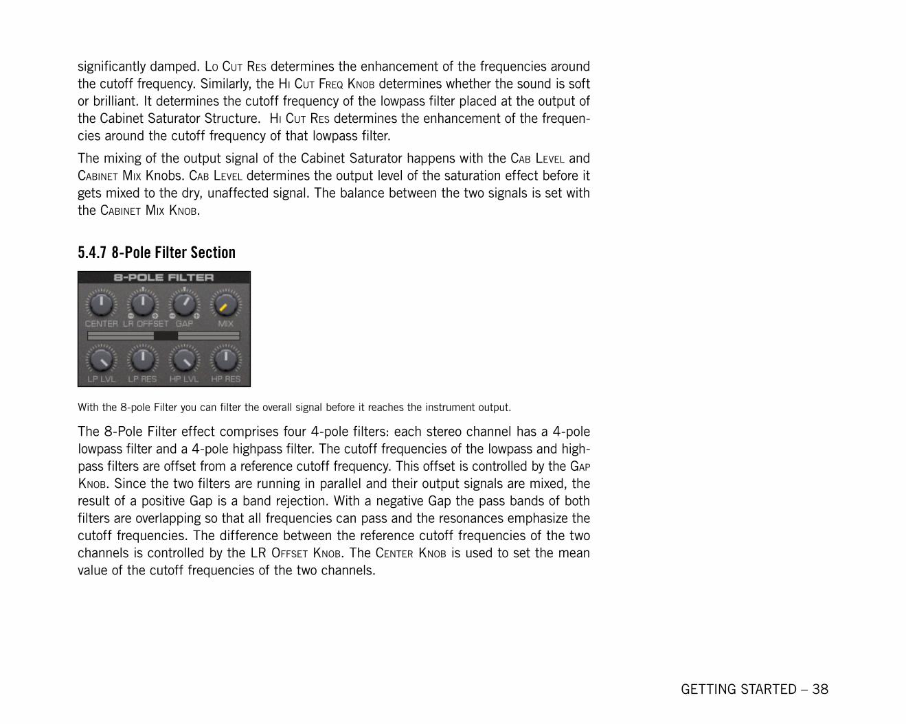
With the 8-pole Filter you can filter the overall signal before it reaches the instrument output.
The 8-Pole Filter effect comprises four 4-pole filters: each stereo channel has a 4-pole lowpass filter and a 4-pole highpass filter. The cutoff frequencies of the lowpass and high-pass filters are offset from a reference cutoff frequency. This offset is controlled by the gaP knoB. Since the two filters are running in parallel and their output signals are mixed, the result of a positive Gap is a band rejection. With a negative Gap the pass bands of both filters are overlapping so that all frequencies can pass and the resonances emphasize the cutoff frequencies. The difference between the reference cutoff frequencies of the two channels is controlled by the lr oFFSet knoB. The center knoB is used to set the mean value of the cutoff frequencies of the two channels.
GETTING STARTED – 39
5.4.8 Mod Delay Section
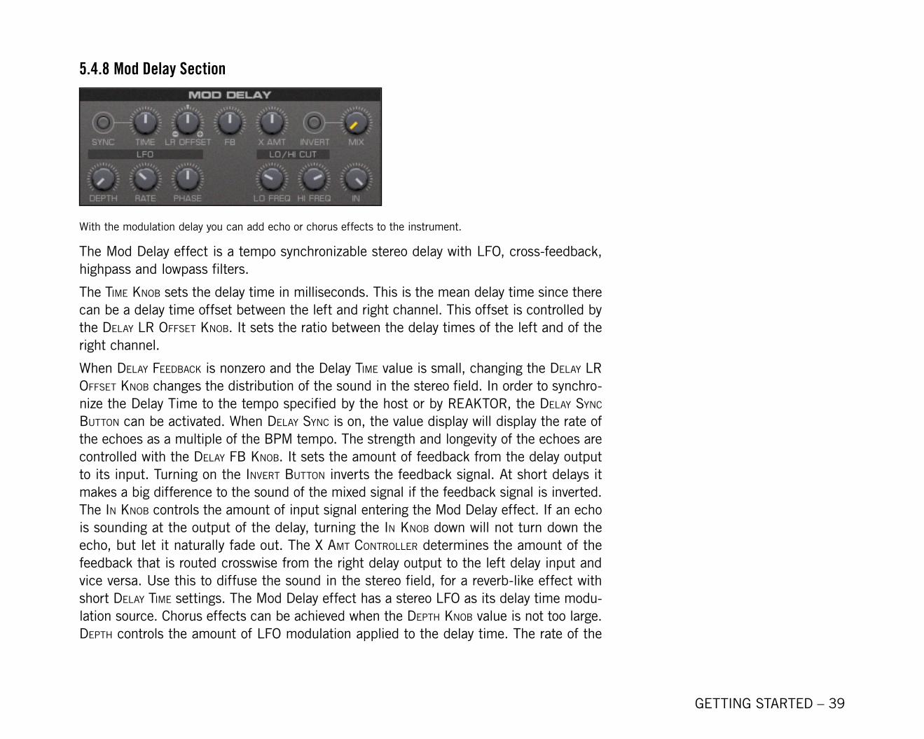
With the modulation delay you can add echo or chorus effects to the instrument.
The Mod Delay effect is a tempo synchronizable stereo delay with LFO, cross-feedback, highpass and lowpass filters.
The tiMe knoB sets the delay time in milliseconds. This is the mean delay time since there can be a delay time offset between the left and right channel. This offset is controlled by the delay lr oFFSet knoB. It sets the ratio between the delay times of the left and of the right channel.
When delay FeedBack is nonzero and the Delay tiMe value is small, changing the delay lr oFFSet knoB changes the distribution of the sound in the stereo field. In order to synchro-nize the Delay Time to the tempo specified by the host or by REAKTOR, the delay Sync Button can be activated. When delay Sync is on, the value display will display the rate of the echoes as a multiple of the BPM tempo. The strength and longevity of the echoes are controlled with the delay FB knoB. It sets the amount of feedback from the delay output to its input. Turning on the invert Button inverts the feedback signal. At short delays it makes a big difference to the sound of the mixed signal if the feedback signal is inverted. The in knoB controls the amount of input signal entering the Mod Delay effect. If an echo is sounding at the output of the delay, turning the in knoB down will not turn down the echo, but let it naturally fade out. The x aMt controller determines the amount of the feedback that is routed crosswise from the right delay output to the left delay input and vice versa. Use this to diffuse the sound in the stereo field, for a reverb-like effect with short delay tiMe settings. The Mod Delay effect has a stereo LFO as its delay time modu-lation source. Chorus effects can be achieved when the dePth knoB value is not too large. dePth controls the amount of LFO modulation applied to the delay time. The rate of the
GETTING STARTED – �0
LFO is determined by the setting of the rate knoB. For additional stereo manipulation, the relative phase between the LFOs applied to the right and left stereo channels can be controlled by the PhaSe knoB. Setting the PhaSe knoB to 0.0 yields the same phase for both channels, 0.5 yields a 90 degree phase shift and 1.0 yields a 180 degree phase shift. The lower frequencies of the delayed signal can be damped using the delay lo cut controller. It determines the cutoff frequency of the highpass filter placed after the delay. Similarly, the delay hi cut controller sets the cutoff frequency above which the higher frequencies are damped.
5.4.9 Reverb Section
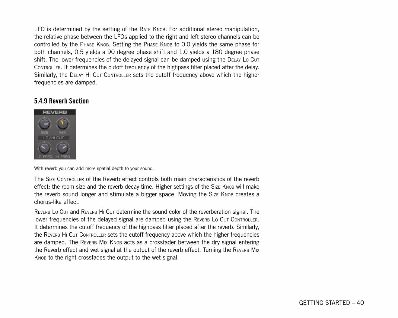
With reverb you can add more spatial depth to your sound.
The Size controller of the Reverb effect controls both main characteristics of the reverb effect: the room size and the reverb decay time. Higher settings of the Size knoB will make the reverb sound longer and stimulate a bigger space. Moving the Size knoB creates a chorus-like effect.
reverB lo cut and reverB hi cut determine the sound color of the reverberation signal. The lower frequencies of the delayed signal are damped using the reverB lo cut controller. It determines the cutoff frequency of the highpass filter placed after the reverb. Similarly, the reverB hi cut controller sets the cutoff frequency above which the higher frequencies are damped. The reverB Mix knoB acts as a crossfader between the dry signal entering the Reverb effect and wet signal at the output of the reverb effect. Turning the reverB Mix knoB to the right crossfades the output to the wet signal.
GETTING STARTED – �1
5.4.10 Oscillator Envelope Section
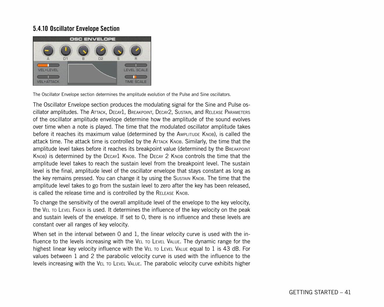
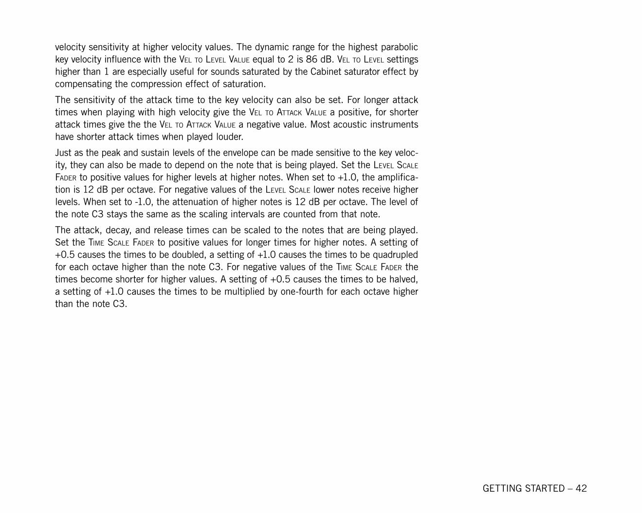
The Oscillator Envelope section determines the amplitude evolution of the Pulse and Sine oscillators.
The Oscillator Envelope section produces the modulating signal for the Sine and Pulse os-cillator amplitudes. The attack, decay1, BreakPoint, decay2, SuStain, and releaSe ParaMeterS of the oscillator amplitude envelope determine how the amplitude of the sound evolves over time when a note is played. The time that the modulated oscillator amplitude takes before it reaches its maximum value (determined by the aMPlitude knoB), is called the attack time. The attack time is controlled by the attack knoB. Similarly, the time that the amplitude level takes before it reaches its breakpoint value (determined by the BreakPoint knoB) is determined by the decay1 knoB. The decay 2 knoB controls the time that the amplitude level takes to reach the sustain level from the breakpoint level. The sustain level is the final, amplitude level of the oscillator envelope that stays constant as long as the key remains pressed. You can change it by using the SuStain knoB. The time that the amplitude level takes to go from the sustain level to zero after the key has been released, is called the release time and is controlled by the releaSe knoB.
To change the sensitivity of the overall amplitude level of the envelope to the key velocity, the vel to level Fader is used. It determines the influence of the key velocity on the peak and sustain levels of the envelope. If set to 0, there is no influence and these levels are constant over all ranges of key velocity.
When set in the interval between 0 and 1, the linear velocity curve is used with the in-fluence to the levels increasing with the vel to level value. The dynamic range for the highest linear key velocity influence with the vel to level value equal to 1 is �3 dB. For values between 1 and 2 the parabolic velocity curve is used with the influence to the levels increasing with the vel to level value. The parabolic velocity curve exhibits higher
GETTING STARTED – �2
velocity sensitivity at higher velocity values. The dynamic range for the highest parabolic key velocity influence with the vel to level value equal to 2 is 86 dB. vel to level settings higher than 1 are especially useful for sounds saturated by the Cabinet saturator effect by compensating the compression effect of saturation.
The sensitivity of the attack time to the key velocity can also be set. For longer attack times when playing with high velocity give the vel to attack value a positive, for shorter attack times give the the vel to attack value a negative value. Most acoustic instruments have shorter attack times when played louder.
Just as the peak and sustain levels of the envelope can be made sensitive to the key veloc-ity, they can also be made to depend on the note that is being played. Set the level Scale Fader to positive values for higher levels at higher notes. When set to +1.0, the amplifica-tion is 12 dB per octave. For negative values of the level Scale lower notes receive higher levels. When set to -1.0, the attenuation of higher notes is 12 dB per octave. The level of the note C3 stays the same as the scaling intervals are counted from that note.
The attack, decay, and release times can be scaled to the notes that are being played. Set the tiMe Scale Fader to positive values for longer times for higher notes. A setting of +0.5 causes the times to be doubled, a setting of +1.0 causes the times to be quadrupled for each octave higher than the note C3. For negative values of the tiMe Scale Fader the times become shorter for higher values. A setting of +0.5 causes the times to be halved, a setting of +1.0 causes the times to be multiplied by one-fourth for each octave higher than the note C3.
GETTING STARTED – �3
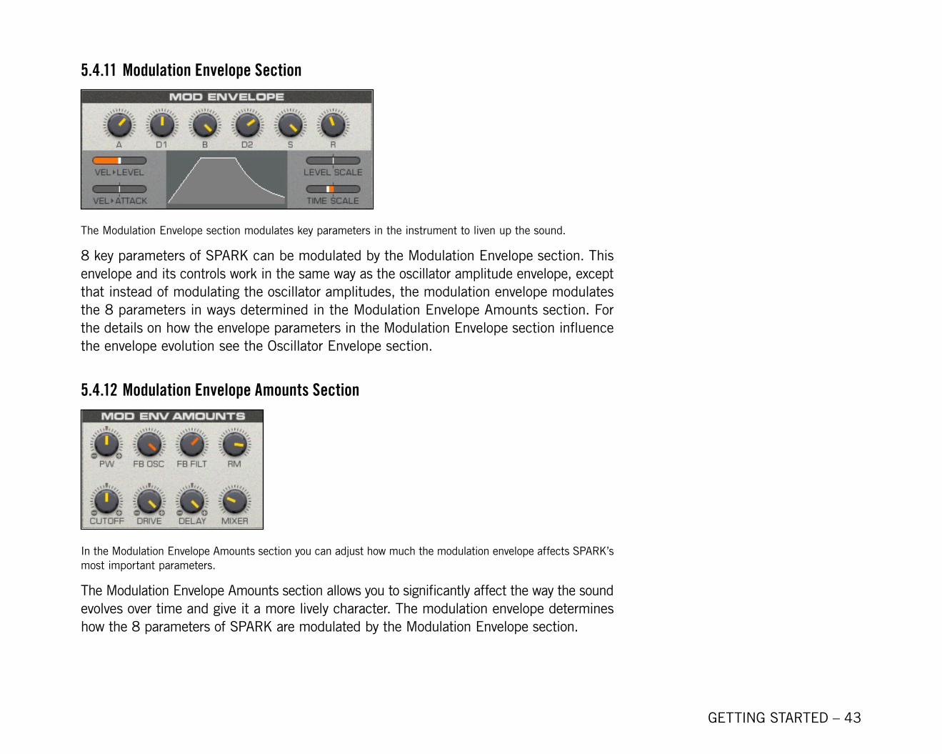
5.4.11 Modulation Envelope Section
The Modulation Envelope section modulates key parameters in the instrument to liven up the sound.
8 key parameters of SPARK can be modulated by the Modulation Envelope section. This envelope and its controls work in the same way as the oscillator amplitude envelope, except that instead of modulating the oscillator amplitudes, the modulation envelope modulates the 8 parameters in ways determined in the Modulation Envelope Amounts section. For the details on how the envelope parameters in the Modulation Envelope section influence the envelope evolution see the Oscillator Envelope section.
5.4.12 Modulation Envelope Amounts Section
In the Modulation Envelope Amounts section you can adjust how much the modulation envelope affects SPARK’s most important parameters.
The Modulation Envelope Amounts section allows you to significantly affect the way the sound evolves over time and give it a more lively character. The modulation envelope determines how the 8 parameters of SPARK are modulated by the Modulation Envelope section.
GETTING STARTED – ��
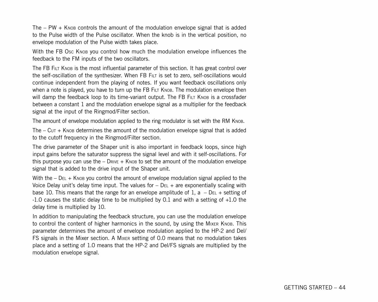
The – PW + knoB controls the amount of the modulation envelope signal that is added to the Pulse width of the Pulse oscillator. When the knob is in the vertical position, no envelope modulation of the Pulse width takes place.
With the FB oSc knoB you control how much the modulation envelope influences the feedback to the FM inputs of the two oscillators.
The FB Filt knoB is the most influential parameter of this section. It has great control over the self-oscillation of the synthesizer. When FB Filt is set to zero, self-oscillations would continue independent from the playing of notes. If you want feedback oscillations only when a note is played, you have to turn up the FB Filt knoB. The modulation envelope then will damp the feedback loop to its time-variant output. The FB Filt knoB is a crossfader between a constant 1 and the modulation envelope signal as a multiplier for the feedback signal at the input of the Ringmod/Filter section.
The amount of envelope modulation applied to the ring modulator is set with the rM knoB.
The – cut + knoB determines the amount of the modulation envelope signal that is added to the cutoff frequency in the Ringmod/Filter section.
The drive parameter of the Shaper unit is also important in feedback loops, since high input gains before the saturator suppress the signal level and with it self-oscillations. For this purpose you can use the – drive + knoB to set the amount of the modulation envelope signal that is added to the drive input of the Shaper unit.
With the – del + knoB you control the amount of envelope modulation signal applied to the Voice Delay unit’s delay time input. The values for – del + are exponentially scaling with base 10. This means that the range for an envelope amplitude of 1, a – del + setting of -1.0 causes the static delay time to be multiplied by 0.1 and with a setting of +1.0 the delay time is multiplied by 10.
In addition to manipulating the feedback structure, you can use the modulation envelope to control the content of higher harmonics in the sound, by using the Mixer knoB. This parameter determines the amount of envelope modulation applied to the HP-2 and Del/FS signals in the Mixer section. A Mixer setting of 0.0 means that no modulation takes place and a setting of 1.0 means that the HP-2 and Del/FS signals are multiplied by the modulation envelope signal.
GETTING STARTED – �5
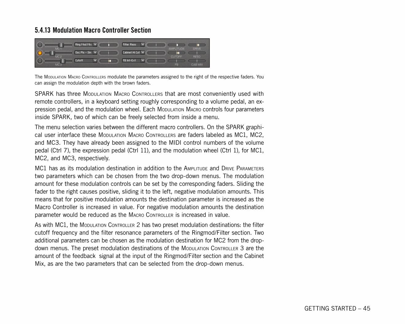
5.4.13 Modulation Macro Controller Section
The Modulation Macro controllerS modulate the parameters assigned to the right of the respective faders. You can assign the modulation depth with the brown faders.
SPARK has three Modulation Macro controllerS that are most conveniently used with remote controllers, in a keyboard setting roughly corresponding to a volume pedal, an ex-pression pedal, and the modulation wheel. Each Modulation Macro controls four parameters inside SPARK, two of which can be freely selected from inside a menu.
The menu selection varies between the different macro controllers. On the SPARK graphi-cal user interface these Modulation Macro controllerS are faders labeled as Mc1, Mc2, and Mc3. They have already been assigned to the MIDI control numbers of the volume pedal (Ctrl 7), the expression pedal (Ctrl 11), and the modulation wheel (Ctrl 1), for Mc1, Mc2, and Mc3, respectively.
MC1 has as its modulation destination in addition to the aMPlitude and drive ParaMeterS two parameters which can be chosen from the two drop-down menus. The modulation amount for these modulation controls can be set by the corresponding faders. Sliding the fader to the right causes positive, sliding it to the left, negative modulation amounts. This means that for positive modulation amounts the destination parameter is increased as the Macro Controller is increased in value. For negative modulation amounts the destination parameter would be reduced as the Macro controller is increased in value.
As with Mc1, the Modulation controller 2 has two preset modulation destinations: the filter cutoff frequency and the filter resonance parameters of the Ringmod/Filter section. Two additional parameters can be chosen as the modulation destination for Mc2 from the drop-down menus. The preset modulation destinations of the Modulation controller 3 are the amount of the feedback signal at the input of the Ringmod/Filter section and the Cabinet Mix, as are the two parameters that can be selected from the drop-down menus.

GETTING STARTED – �6
5.4.14 LFO Section
With these controls you can adjust the main LFO parameters.
SPARK also has an LFO with a triangle waveform with adjustable symmetry and clipping as an internal source of periodic controller movements. It can replace the automation of the host sequencer or the pedal movements and lets you get your hands free for sound modifications. The LFO can have four destinations: the Modulation controllerS 1, 2, and 3, and the velocity controller. The routing of the modulation signal to each destination can be switched on or off with the to vel, to Mc1, to Mc2, and to Mc3 ButtonS for the Velocity Controller, MC1, MC2, and MC3, respectively. These buttons are located on the left of the corresponding controller’s fader.
When the button is alight, it means that the controller destination is receiving the LFO modulation signal. How the LFO modulates the controller is reflected graphically in the fader’s movements. The amount of LFO modulation to the destinations is dictated by the lFo aMount knoB. It controls the peak to peak amplitude of the LFO signal. If the des-tination is positioned in the middle of its full range, an lFo aMount setting of 1.0 would move the controller over its entire range.
The lFo rate knoB controls the frequency of the LFO. The units of the lFo rate depend on the state of the lFo Sync Button. If lFo Sync is off, lFo rate is given in Hz. If lFo Sync is on, the lFo rate is given in oscillations per beat. The key Sync Button causes the LFO to be reset to zero at every note-on event. If key Sync is off and lFo Sync is on, the LFO phase also is synchronized to the song position. SeeSee rand ParaMeter for a description of the note-on event. The static phase of the LFO is controlled by the The static phase of the LFO is controlled by the lFo PhaSe knoB. It shifts the LFO phase in relation to the song position when key Sync is off. When key Sync is off, the lFo PhaSe knoB determines the phase of the LFO at a note-on event. An lFo PhaSe of -1 corresponds to the zero crossing of the waveform’s falling ramp. Similarly, -0.5 corresponds to the lower peak of the LFO waveform, 0 to the zero crossing of the rising ramp, +0.5 to the upper peak, and +1 again to the zero crossing the falling ramp.
GETTING STARTED – �7
To give you more control over the shape of the LFO waveform, the cliP, cliP SyM, and tri SyM ParaMeterS are can be manipulated. The qualitative effect that the latter two param-eters have on the LFO waveform can be seen in the cliP SyM and tri SyM FieldS.
The original waveform of the LFO is a triangle. The symmetry of the two ramps of the triangle can be set using the tri SyM Field. Positive values increase the speed of the rising ramp which yields a falling sawtooth for a value of +1, a symmetric triangle for 0, and a rising sawtooth for -1 as the tri SyM value.
The cliP knoB dictates the amount of clipping of the LFO waveform. At zero it’s a triangle waveform and with increasing values it becomes more like a rectangular waveform. The effect of the clipping on the LFO waveform can further be manipulated by changing the clipping symmetry. This is done with the cliP SyM Field. At positive values the upper part of the waveform, for negative values the lower part of the waveform is clipped harder. When cliP SyM is set to +1 there is no clipping at the negative part of the waveform, and for -1 there is no clipping at the positive part of the waveform.
GETTING STARTED – �8
6. CreditsSound Design: Alex Hofmann, Denis Gökdag (Surround SFX), Dietrich Pank, Ema Jolly, Eoin Rossney, Gustavo Bravetti, Jörg Hüttner, Jeremiah Savage, Martin Backes, Matthias Fuchs (Visophon), Stephan Schmitt, Thomas Binek (Tasmodia), Thomas Koot, Tobias Menguser
KORE SOUNDPACK design by Tobias Menguser.
Additional Sound Treatment & Variations by Alex Hofmann & Tobias Menguser.
SPARK Ensemble created by Stephan Schmitt.
Graphics Design for SPARK by Phirol.