Embed Size (px)
Citation preview
New Jersey Home Performance with ENERGY STAR®
Real Home Analyzer Software
Users Manual
Conservation Services Group 75 Lincoln Highway, Suite 100 Iselin, NJ 08830
NJ HPwES RHA User Guide 2/90 v07.20.12
Table of Contents
LOGGING IN ........................................................................................................................................................... 5
Citrix Website............................................................................................................................................... 5
Real Home Analyzer (RHA) ............................................................................................................................ 6
RHA NAVIGATION .................................................................................................................................................. 7
Standard Icons ............................................................................................................................................. 7
Jump Menu .................................................................................................................................................. 7
ADDING A CUSTOMER ........................................................................................................................................... 8
Customer Intake Screen ................................................................................................................................ 9
Address Validation ...................................................................................................................................... 11
Accessing an Existing Customer/Site/Project ................................................................................................ 12
Locked Sites: .............................................................................................................................................. 14
MODELING EXISTING ENERGY USAGE: ................................................................................................................. 14
Building Model: .......................................................................................................................................... 14
Building Layout:........................................................................................................................................................ 15
Shell Basics: .............................................................................................................................................................. 16
Shell Details: ............................................................................................................................................................. 16
Thermostat Settings: ................................................................................................................................................ 17
Demographics: ........................................................................................................................................... 17
Add/ Analyze Usage (Entering Fuel Bills): ...................................................................................................... 17
Reliable Heating Fuel and Electric Usage Guidelines: .............................................................................................. 18
Auto True-Up Procedures: ....................................................................................................................................... 18
Electric & Natural Gas Usage:........................................................................................................ 19
Oil & Propane Usage: ................................................................................................................... 19
Unreliable Fuel Bill Procedure: ................................................................................................................................. 21
Editing Pre-Auto True-up Project: ............................................................................................................................ 21
Heating and Cooling: ................................................................................................................................... 24
Existing Equipment Efficiencies:............................................................................................................................... 24
Furnaces & Boilers ................................................................................................................................................... 25
Adding Systems ........................................................................................................................... 25
Location ...................................................................................................................................... 25
Type ........................................................................................................................................................ 25
Capacity [MBtuh], Fuel, Details, Venting and Manuf Year ............................................................... 26
Details- Heating Equipment: .................................................................................................................... 27
%Load & % Space: ........................................................................................................................ 28
Capacity Weighted % Load: ..................................................................................................................... 28
Distribution: ................................................................................................................................ 29
Editing Duct Locations.............................................................................................................................. 31
Air Conditioning: ...................................................................................................................................................... 33
Air Sourced Heat Pump: ........................................................................................................................................... 33
Geothermal Heat Pump: .......................................................................................................................................... 34
Mini-split systems: ................................................................................................................................................... 34
Hybrids: .................................................................................................................................................................... 35
NJ HPwES RHA User Guide 3/90 v07.20.12
CALCULATING EXISTING USAGE ........................................................................................................................... 36
Analysis and Reports: .................................................................................................................................. 36
Navigation: ............................................................................................................................................................... 36
Checking Heating/ Cooling Energy Usage ................................................................................................................ 37
PROPOSING UPGRADES ....................................................................................................................................... 38
Heating/ Cooling:........................................................................................................................................ 38
Furnaces & Boilers ................................................................................................................................................... 39
Air Source Heat Pump: ............................................................................................................................................. 39
Geothermal Heat Pump: .......................................................................................................................................... 40
Air Conditioning: ...................................................................................................................................................... 40
Mini-split systems: ................................................................................................................................................... 41
Hybrids: .................................................................................................................................................................... 41
Add a Heat Pump to an Existing Furnace ........................................................................................ 41
Model a Hybrid with New Furnace and New Heat Pump ................................................................. 43
Remove/ Add System [Changing HVAC System Type} ............................................................................................. 45
Ducts: ....................................................................................................................................................................... 47
Testing Required .......................................................................................................................... 47
Ducts- RHA Navigation ................................................................................................................. 48
Modify/Replace Distribution: ........................................................................................................ 49
Duct Sealing: ............................................................................................................................... 49
Duct Insulation: ........................................................................................................................... 51
Duct Location- Proposing to change: ............................................................................................. 53
Air sealing: ................................................................................................................................................. 56
Blower Door Testing:................................................................................................................................................ 57
Mechanical Ventilation- Under Development- DO NOT USE ........................................................................... 57
Insulation: .................................................................................................................................................. 57
General Guidelines: .................................................................................................................................................. 57
Section Details: ............................................................................................................................ 57
Existing insulation: ....................................................................................................................... 58
Proposed Insulation: .................................................................................................................... 58
Insulation- Attic / Roof ............................................................................................................................................. 59
Kneewalls: ................................................................................................................................... 60
Conditioned Attics (Bring attic inside thermal boundary): ............................................................... 60
Insulation- Attic Access ............................................................................................................................................ 62
Insulation- Foundation / Floor ................................................................................................................................. 63
Conditioned Crawlspaces (Bring Crawlspace inside thermal boundary): ........................................... 63
Insulation- Wall ........................................................................................................................................................ 65
Windows / Patio Doors: Ineligible measures- DO NOT USE ..................................................................................... 65
Doors: Ineligible measures- DO NOT USE ................................................................................................................ 65
Attic / Roof Ventilation ............................................................................................................................................ 65
DHW- Domestic Hot Water System .............................................................................................................. 66
Heatpump: ............................................................................................................................................................... 66
Indirect Fired: ........................................................................................................................................................... 66
On-Demand: ............................................................................................................................................................. 67
Tank-Standard: ......................................................................................................................................................... 67
NJ HPwES RHA User Guide 4/90 v07.20.12
Tank-high efficiency: ................................................................................................................................................ 68
Tankless and Tankless backup:................................................................................................................................. 68
Combi-boiler units:................................................................................................................................................... 68
Special DHW Products:............................................................................................................................................. 68
Thermal Efficiency (TE): ........................................................................................................................................... 69
DHW- Faucet Aerator: Ineligible measures- DO NOT USE ............................................................................... 69
DHW- Showerhead: Ineligible measures- DO NOT USE .................................................................................. 69
DHW Appliances: Ineligible measures- DO NOT USE ...................................................................................... 70
Lighting- Bulbs: Ineligible measures- DO NOT USE ......................................................................................... 70
Lighting- Fixtures: Ineligible measures- DO NOT USE ..................................................................................... 70
Refrigeration: Ineligible measures- DO NOT USE ........................................................................................... 70
Misc. Parts, Fees, and Discounts: DO NOT USE- ............................................................................................. 70
Do not use Misc. Parts- Use Custom parts, fees and Discounts below ............................................................. 70
Custom parts, fees and Discounts ................................................................................................................ 70
Custom Parts: ........................................................................................................................................................... 70
Health & Safety Measures ....................................................................................................................................... 70
Discounts & Rebates: ............................................................................................................................................... 71
Sub Total: HVAC: ...................................................................................................................................................... 71
ADDING OR REMOVING MEASURES ON A CONTRACT ......................................................................................... 72
TOTAL ENERGY SAVINGS CALCULATOR ................................................................................................................ 77
PROPOSED MEASURES DOCUMENT ..................................................................................................................... 78
CLAIMING FUNDS FOR A PROJECT ....................................................................................................................... 80
Claim 2012 HPwES Incentives ...................................................................................................................... 81
Expiration and Extensions: .......................................................................................................................... 83
Rebate Assignment ..................................................................................................................................... 82
Customer Utility Information: ...................................................................................................................... 83
FIELD CHANGE ORDER ......................................................................................................................................... 83
COMPLETING A PROJECT ..................................................................................................................................... 84
Flag Installed .............................................................................................................................................. 85
Flag Contract as Completed ......................................................................................................................... 85
CERTIFICATE OF COMPLETION ............................................................................................................................. 86
CHECKING PROJECT STATUS................................................................................................................................. 87
Project Viewer ............................................................................................................................................ 87
Milestones ................................................................................................................................................. 88
NJ HPwES RHA User Guide 5/90 v07.20.12
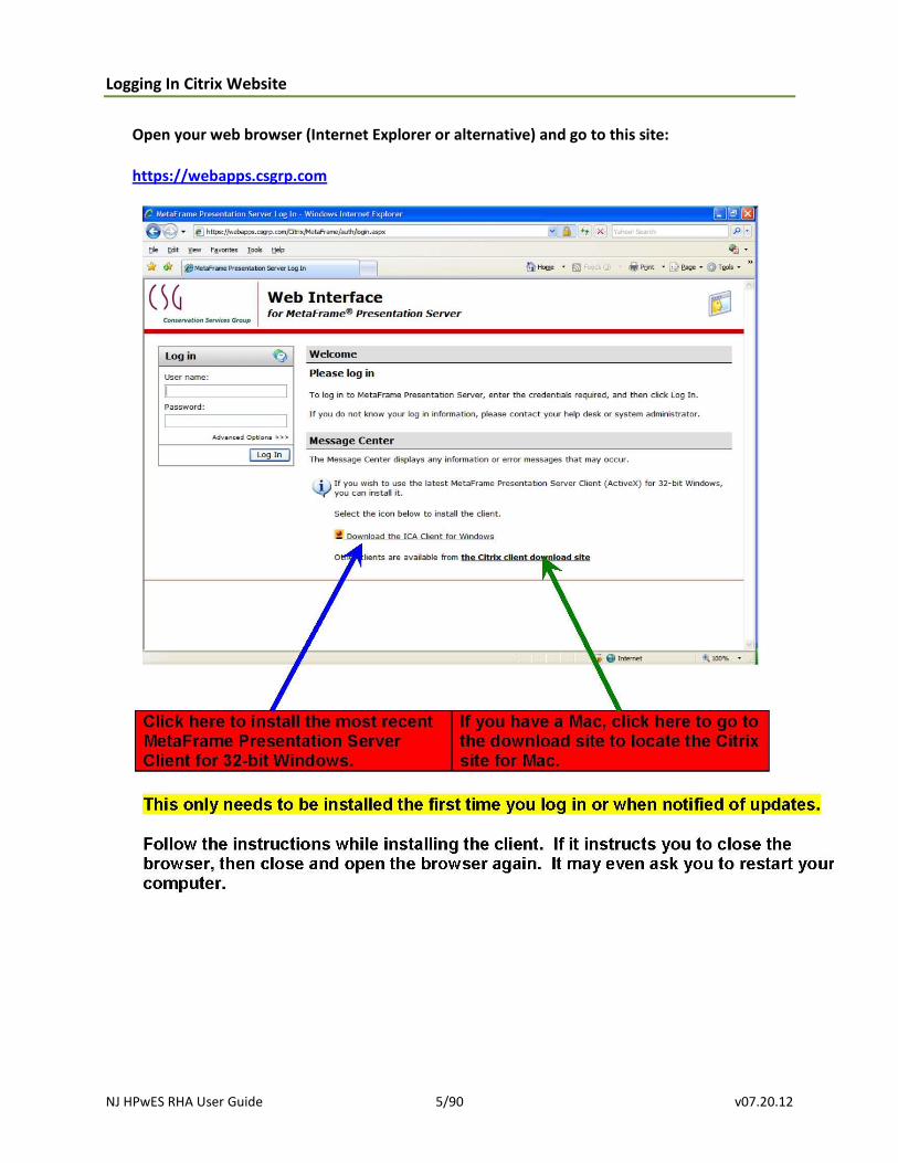
Logging In Citrix Website
Open your web browser (Internet Explorer or alternative) and go to this site: https://webapps.csgrp.com
NJ HPwES RHA User Guide 6/90 v07.20.12
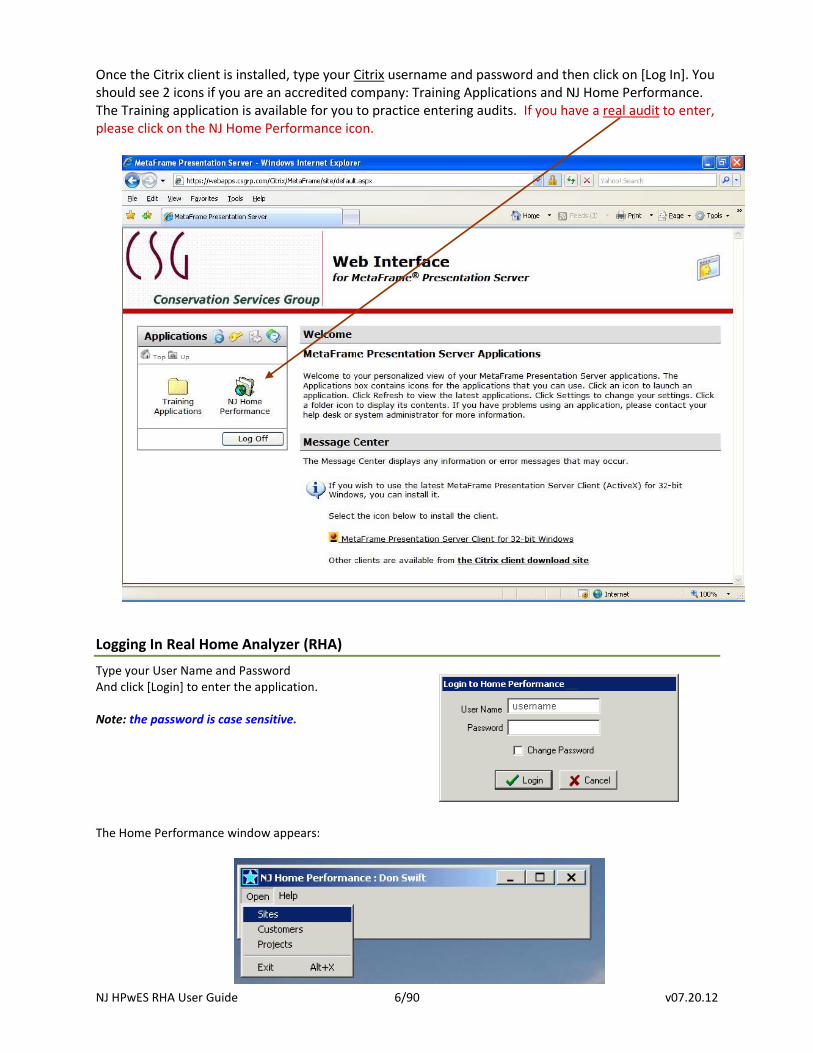
Once the Citrix client is installed, type your Citrix username and password and then click on [Log In]. You should see 2 icons if you are an accredited company: Training Applications and NJ Home Performance. The Training application is available for you to practice entering audits. If you have a real audit to enter, please click on the NJ Home Performance icon.
Logging In Real Home Analyzer (RHA)
Type your User Name and Password And click [Login] to enter the application.
Note: the password is case sensitive.
The Home Performance window appears:
NJ HPwES RHA User Guide 7/90 v07.20.12
RHA Navigation
Customer: description of customer name, contact information and preferences
Site: description of the dwelling; address, current condition and proposed improvements
Project: description of the Program under which the work is being done, type of work and contract information.
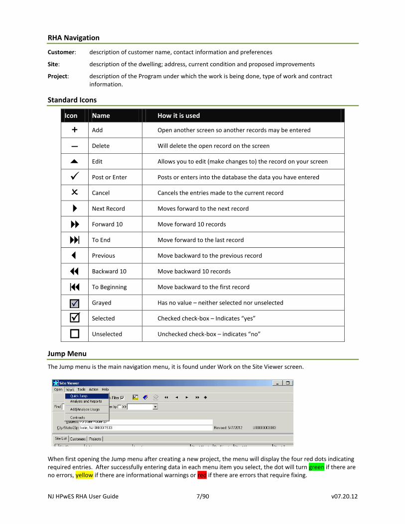
Standard Icons
Icon Name How it is used
Add Open another screen so another records may be entered
– Delete Will delete the open record on the screen
Edit Allows you to edit (make changes to) the record on your screen
Post or Enter Posts or enters into the database the data you have entered
Cancel Cancels the entries made to the current record
Next Record Moves forward to the next record
Forward 10 Move forward 10 records
To End Move forward to the last record
Previous Move backward to the previous record
Backward 10 Move backward 10 records
To Beginning Move backward to the first record
Grayed Has no value – neither selected nor unselected
Selected Checked check-box – Indicates “yes”
Unselected Unchecked check-box – indicates “no”
Jump Menu
The Jump menu is the main navigation menu, it is found under Work on the Site Viewer screen.
When first opening the Jump menu after creating a new project, the menu will display the four red dots indicating required entries. After successfully entering data in each menu item you select, the dot will turn green if there are no errors, yellow if there are informational warnings or red if there are errors that require fixing.
NJ HPwES RHA User Guide 8/90 v07.20.12
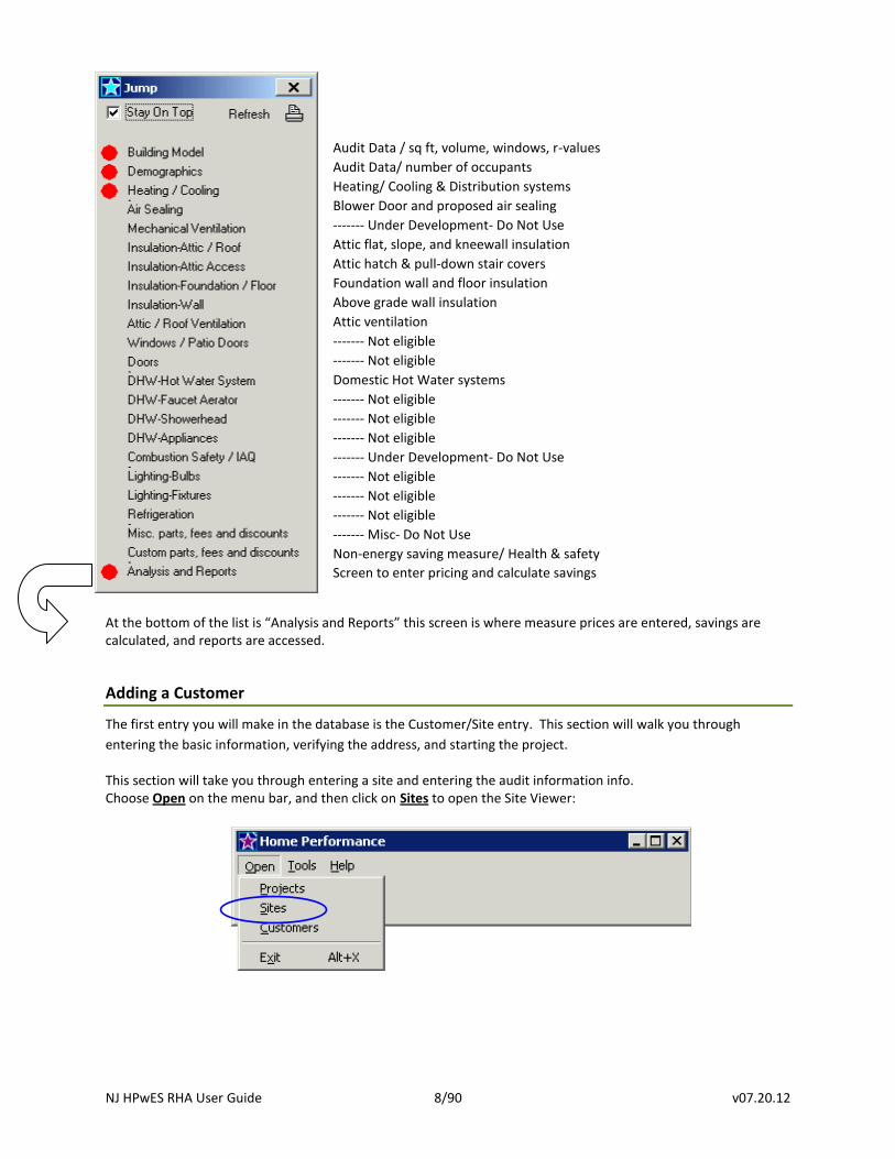
At the bottom of the list is “Analysis and Reports” this screen is where measure prices are entered, savings are calculated, and reports are accessed.
Adding a Customer
The first entry you will make in the database is the Customer/Site entry. This section will walk you through
entering the basic information, verifying the address, and starting the project.
This section will take you through entering a site and entering the audit information info. Choose Open on the menu bar, and then click on Sites to open the Site Viewer:
Audit Data / sq ft, volume, windows, r-values
Audit Data/ number of occupants
Heating/ Cooling & Distribution systems
Blower Door and proposed air sealing
------- Under Development- Do Not Use
Attic flat, slope, and kneewall insulation
Attic hatch & pull-down stair covers
Foundation wall and floor insulation
Above grade wall insulation
Attic ventilation
------- Not eligible
------- Not eligible
Domestic Hot Water systems
------- Not eligible
------- Not eligible
------- Not eligible
------- Under Development- Do Not Use
------- Not eligible
------- Not eligible
------- Not eligible
------- Misc- Do Not Use
Non-energy saving measure/ Health & safety
Screen to enter pricing and calculate savings
NJ HPwES RHA User Guide 9/90 v07.20.12
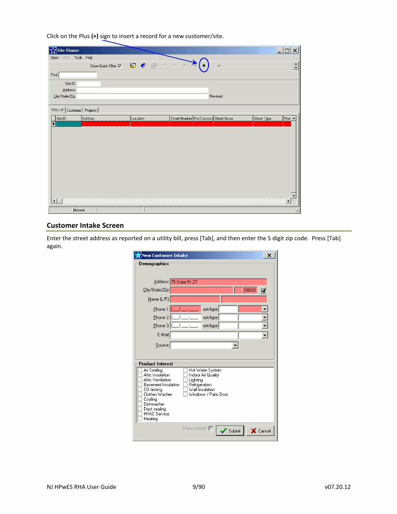
Click on the Plus (+) sign to insert a record for a new customer/site.
Customer Intake Screen Enter the street address as reported on a utility bill, press [Tab], and then enter the 5 digit zip code. Press [Tab] again.
NJ HPwES RHA User Guide 10/90 v07.20.12
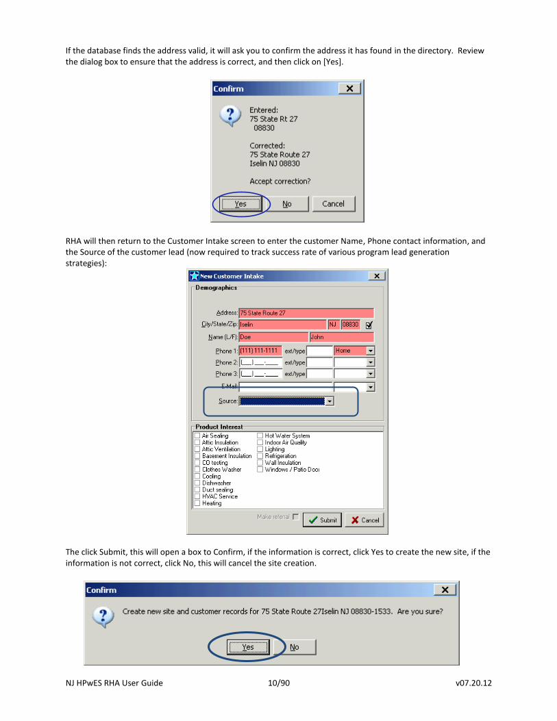
If the database finds the address valid, it will ask you to confirm the address it has found in the directory. Review the dialog box to ensure that the address is correct, and then click on [Yes].
RHA will then return to the Customer Intake screen to enter the customer Name, Phone contact information, and the Source of the customer lead (now required to track success rate of various program lead generation strategies):
The click Submit, this will open a box to Confirm, if the information is correct, click Yes to create the new site, if the information is not correct, click No, this will cancel the site creation.
NJ HPwES RHA User Guide 11/90 v07.20.12
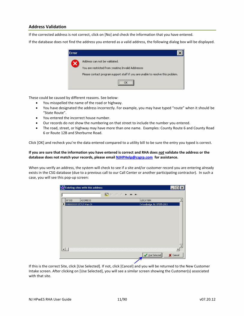
Address Validation
If the corrected address is not correct, click on [No] and check the information that you have entered.
If the database does not find the address you entered as a valid address, the following dialog box will be displayed.
These could be caused by different reasons. See below:
You misspelled the name of the road or highway.
You have designated the address incorrectly. For example, you may have typed “route” when it should be “State Route”.
You entered the incorrect house number.
Our records do not show the numbering on that street to include the number you entered.
The road, street, or highway may have more than one name. Examples: County Route 6 and County Road 6 or Route 12B and Sherburne Road.
Click *OK+ and recheck you’re the data entered compared to a utility bill to be sure the entry you typed is correct.
If you are sure that the information you have entered is correct and RHA does not validate the address or the database does not match your records, please email [email protected] for assistance.
When you verify an address, the system will check to see if a site and/or customer record you are entering already exists in the CSG database (due to a previous call to our Call Center or another participating contractor). In such a case, you will see this pop-up screen:
If this is the correct Site, click [Use Selected]. If not, click [Cancel] and you will be returned to the New Customer Intake screen. After clicking on [Use Selected], you will see a similar screen showing the Customer(s) associated with that site.
NJ HPwES RHA User Guide 12/90 v07.20.12
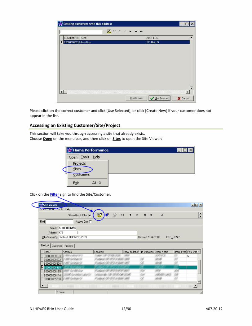
Please click on the correct customer and click [Use Selected], or click [Create New] if your customer does not appear in the list.
Accessing an Existing Customer/Site/Project
This section will take you through accessing a site that already exists. Choose Open on the menu bar, and then click on Sites to open the Site Viewer:
Click on the Filter sign to find the Site/Customer.
NJ HPwES RHA User Guide 13/90 v07.20.12
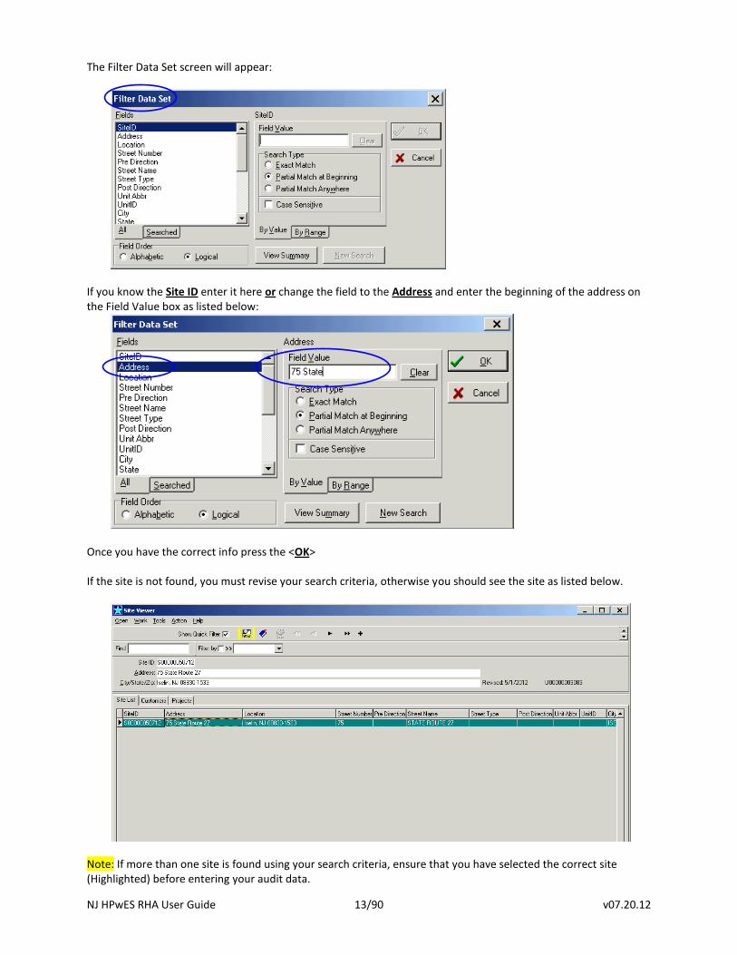
The Filter Data Set screen will appear:
If you know the Site ID enter it here or change the field to the Address and enter the beginning of the address on the Field Value box as listed below:
Once you have the correct info press the <OK> If the site is not found, you must revise your search criteria, otherwise you should see the site as listed below.
Note: If more than one site is found using your search criteria, ensure that you have selected the correct site (Highlighted) before entering your audit data.
NJ HPwES RHA User Guide 14/90 v07.20.12
Locked Sites:
If the site has a project under contract by another contractor, you will not be able to edit any information. Contact the Program via email to [email protected] and provide the address of the site and that it appears under contract. CSG will review the site and if the incentives are not Claimed (i.e. there is no committal), CSG will release the site to you. If the project has a completed Claim (i.e. a committal has been made), CSG will contact the other contractor and request a status of the project that is under contract, if the contractor responds it is still under contract you will be notified, if the contractor states the contract has been voided, CSG will release the site to you.
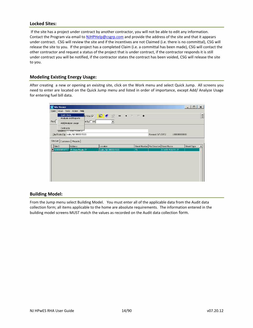
Modeling Existing Energy Usage:
After creating a new or opening an exisitng site, click on the Work menu and select Quick Jump. All screens you need to enter are located on the Quick Jump menu and listed in order of importance, except Add/ Analyze Usage for entering fuel bill data.
Building Model:
From the Jump menu select Building Model. You must enter all of the applicable data from the Audit data collection form; all items applicable to the home are absolute requirements. The information entered in the
building model screens MUST match the values as recorded on the Audit data collection form.
NJ HPwES RHA User Guide 15/90 v07.20.12
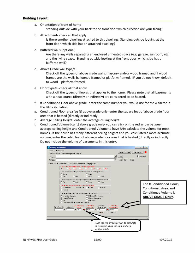
Building Layout:
a. Orientation of front of home Standing outside with your back to the front door which direction are your facing?
b. Attachment- check all that apply Is there another dwelling attached to this dwelling. Standing outside looking at the front door, which side has an attached dwelling?
c. Buffered walls (optional) Are there any walls separating an enclosed unheated space (e.g. garage, sunroom, etc) and the living space. Standing outside looking at the front door, which side has a buffered wall?
d. Above Grade wall type/s Check off the type/s of above grade walls, masonry and/or wood framed and if wood framed are the walls ballooned framed or platform framed. IF you do not know, default to wood – platform framed.
e. Floor type/s- check all that apply Check off the type/s of floor/s that applies to the home. Please note that all basements with a heat source (directly or indirectly) are considered to be heated.
f. # Conditioned Floor above grade- enter the same number you would use for the N factor in the BAS calculation.
g. Conditioned Floor area [sq ft] above grade only- enter the square feet of above grade floor area that is heated (directly or indirectly).
h. Average Ceiling Height- enter the average ceiling height i. Conditioned Volume [cu ft] above grade only- you can click on the red arrow between
average ceiling height and Conditioned Volume to have RHA calculate the volume for most homes. If the house has many different ceiling heights and you calculated a more accurate volume, enter the cubic feet of above grade floor area that is heated (directly or indirectly). Do not include the volume of basements in this entry.
Click the red arrow for RHA to calculate
the volume using the sq ft and avg ceiling height
The # Conditioned Floors, Conditioned Area, and Conditioned Volume is ABOVE GRADE ONLY.
NJ HPwES RHA User Guide 16/90 v07.20.12
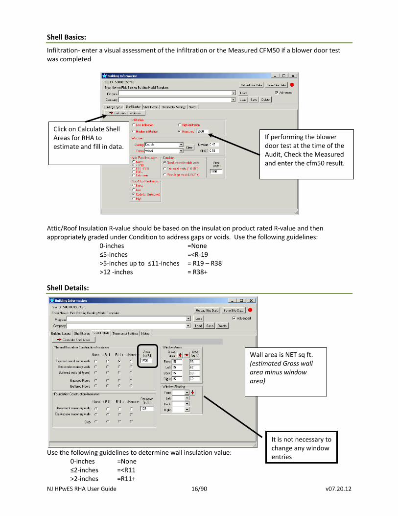
Shell Basics:
Infiltration- enter a visual assessment of the infiltration or the Measured CFM50 if a blower door test was completed
Attic/Roof Insulation R-value should be based on the insulation product rated R-value and then appropriately graded under Condition to address gaps or voids. Use the following guidelines:
0-inches =None ≤5-inches =<R-19 >5-inches up to ≤11-inches = R19 – R38 >12 -inches = R38+
Shell Details:
Use the following guidelines to determine wall insulation value:
0-inches =None ≤2-inches =<R11 >2-inches =R11+
If performing the blower door test at the time of the Audit, Check the Measured and enter the cfm50 result.
Wall area is NET sq ft. (estimated Gross wall area minus window area)
Click on Calculate Shell Areas for RHA to estimate and fill in data.
It is not necessary to change any window entries
NJ HPwES RHA User Guide 17/90 v07.20.12
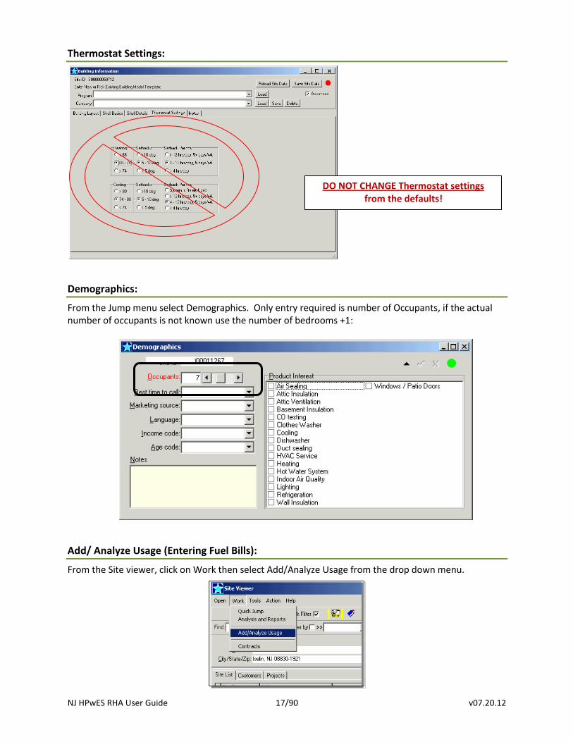
Thermostat Settings:
Demographics:
From the Jump menu select Demographics. Only entry required is number of Occupants, if the actual number of occupants is not known use the number of bedrooms +1:
Add/ Analyze Usage (Entering Fuel Bills):
From the Site viewer, click on Work then select Add/Analyze Usage from the drop down menu.
DO NOT CHANGE Thermostat settings from the defaults!
NJ HPwES RHA User Guide 18/90 v07.20.12
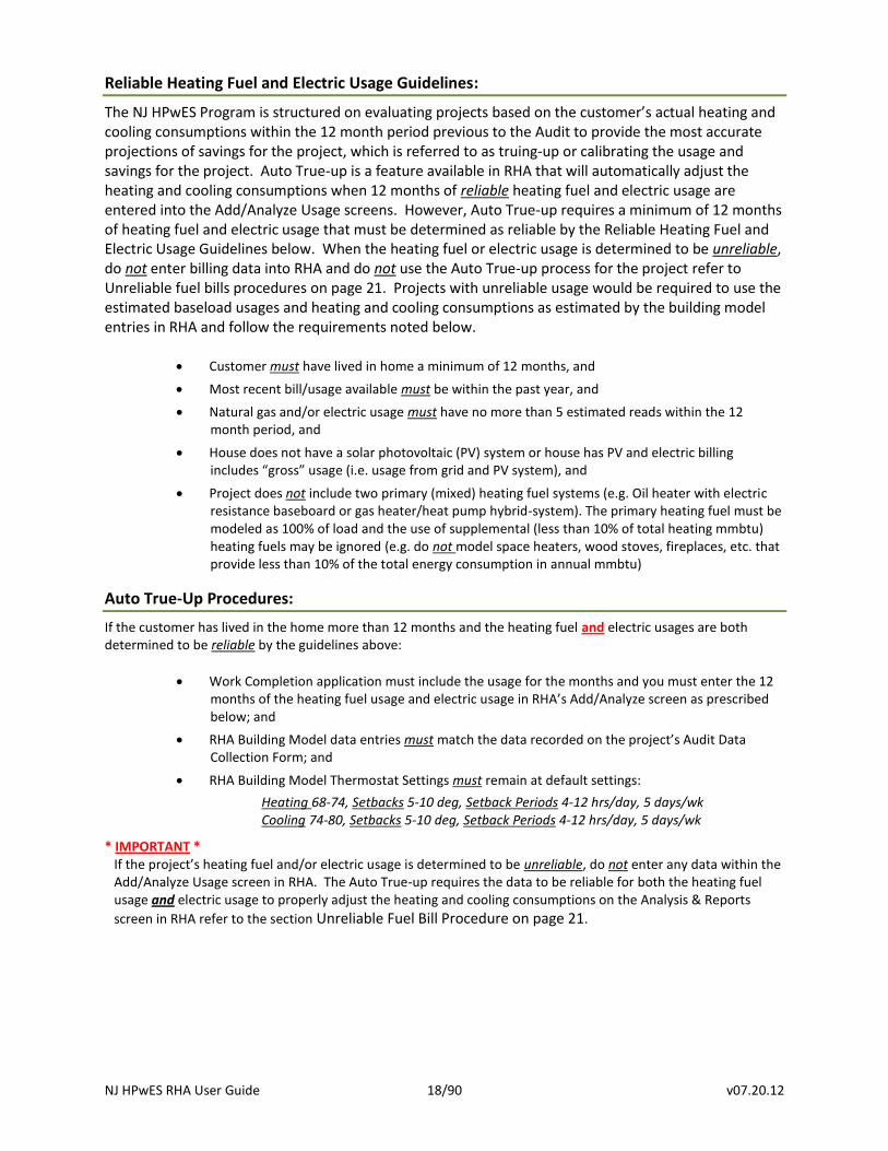
Reliable Heating Fuel and Electric Usage Guidelines:
The NJ HPwES Program is structured on evaluating projects based on the customer’s actual heating and cooling consumptions within the 12 month period previous to the Audit to provide the most accurate projections of savings for the project, which is referred to as truing-up or calibrating the usage and savings for the project. Auto True-up is a feature available in RHA that will automatically adjust the heating and cooling consumptions when 12 months of reliable heating fuel and electric usage are entered into the Add/Analyze Usage screens. However, Auto True-up requires a minimum of 12 months of heating fuel and electric usage that must be determined as reliable by the Reliable Heating Fuel and Electric Usage Guidelines below. When the heating fuel or electric usage is determined to be unreliable, do not enter billing data into RHA and do not use the Auto True-up process for the project refer to Unreliable fuel bills procedures on page 21. Projects with unreliable usage would be required to use the estimated baseload usages and heating and cooling consumptions as estimated by the building model entries in RHA and follow the requirements noted below.
Customer must have lived in home a minimum of 12 months, and
Most recent bill/usage available must be within the past year, and
Natural gas and/or electric usage must have no more than 5 estimated reads within the 12 month period, and
House does not have a solar photovoltaic (PV) system or house has PV and electric billing includes “gross” usage (i.e. usage from grid and PV system), and
Project does not include two primary (mixed) heating fuel systems (e.g. Oil heater with electric resistance baseboard or gas heater/heat pump hybrid-system). The primary heating fuel must be modeled as 100% of load and the use of supplemental (less than 10% of total heating mmbtu) heating fuels may be ignored (e.g. do not model space heaters, wood stoves, fireplaces, etc. that provide less than 10% of the total energy consumption in annual mmbtu)
Auto True-Up Procedures:
If the customer has lived in the home more than 12 months and the heating fuel and electric usages are both determined to be reliable by the guidelines above:
Work Completion application must include the usage for the months and you must enter the 12 months of the heating fuel usage and electric usage in RHA’s Add/Analyze screen as prescribed below; and
RHA Building Model data entries must match the data recorded on the project’s Audit Data Collection Form; and
RHA Building Model Thermostat Settings must remain at default settings:
Heating 68-74, Setbacks 5-10 deg, Setback Periods 4-12 hrs/day, 5 days/wk Cooling 74-80, Setbacks 5-10 deg, Setback Periods 4-12 hrs/day, 5 days/wk
* IMPORTANT * If the project’s heating fuel and/or electric usage is determined to be unreliable, do not enter any data within the Add/Analyze Usage screen in RHA. The Auto True-up requires the data to be reliable for both the heating fuel usage and electric usage to properly adjust the heating and cooling consumptions on the Analysis & Reports
screen in RHA refer to the section Unreliable Fuel Bill Procedure on page 21.
NJ HPwES RHA User Guide 19/90 v07.20.12
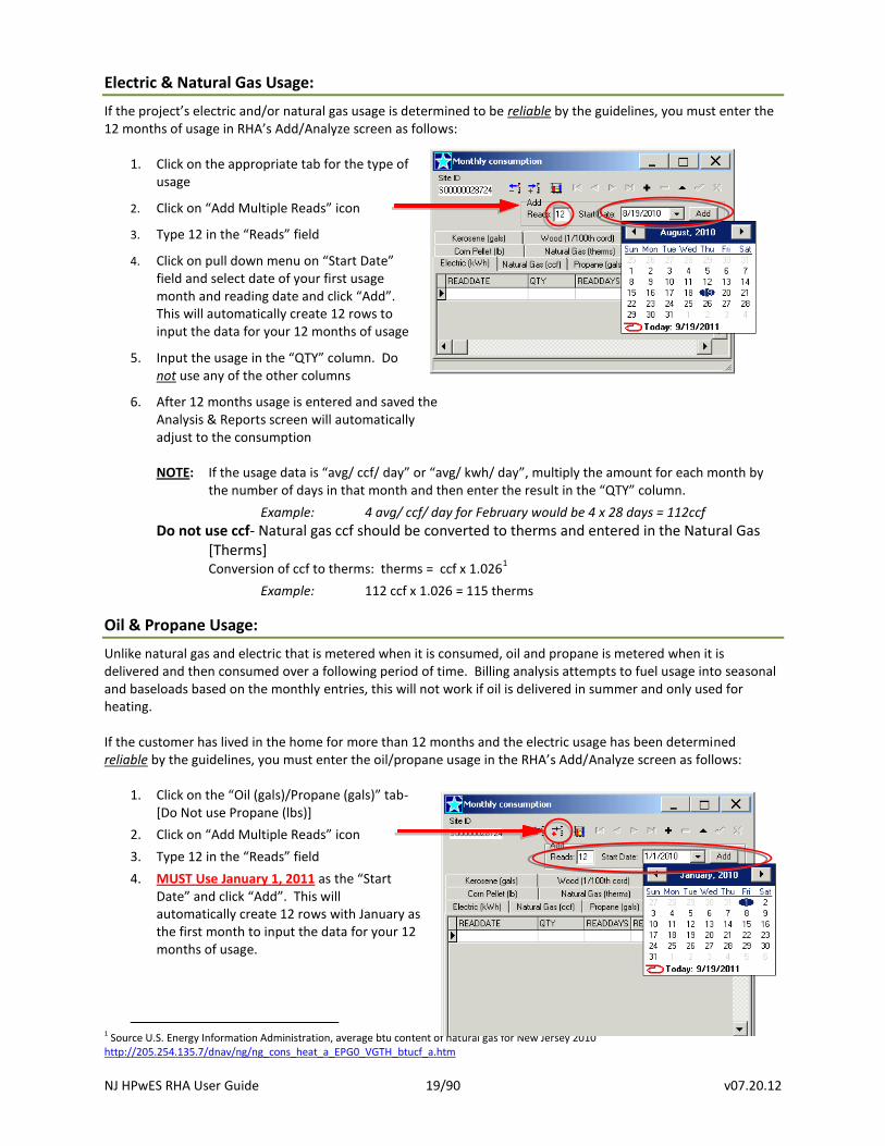
Electric & Natural Gas Usage:
If the project’s electric and/or natural gas usage is determined to be reliable by the guidelines, you must enter the 12 months of usage in RHA’s Add/Analyze screen as follows:
1. Click on the appropriate tab for the type of
usage
2. Click on “Add Multiple Reads” icon
3. Type 12 in the “Reads” field
4. Click on pull down menu on “Start Date” field and select date of your first usage month and reading date and click “Add”. This will automatically create 12 rows to input the data for your 12 months of usage
5. Input the usage in the “QTY” column. Do not use any of the other columns
6. After 12 months usage is entered and saved the Analysis & Reports screen will automatically adjust to the consumption
NOTE: If the usage data is “avg/ ccf/ day” or “avg/ kwh/ day”, multiply the amount for each month by
the number of days in that month and then enter the result in the “QTY” column.
Example: 4 avg/ ccf/ day for February would be 4 x 28 days = 112ccf
Do not use ccf- Natural gas ccf should be converted to therms and entered in the Natural Gas [Therms]
Conversion of ccf to therms: therms = ccf x 1.0261
Example: 112 ccf x 1.026 = 115 therms
Oil & Propane Usage:
Unlike natural gas and electric that is metered when it is consumed, oil and propane is metered when it is delivered and then consumed over a following period of time. Billing analysis attempts to fuel usage into seasonal and baseloads based on the monthly entries, this will not work if oil is delivered in summer and only used for heating. If the customer has lived in the home for more than 12 months and the electric usage has been determined reliable by the guidelines, you must enter the oil/propane usage in the RHA’s Add/Analyze screen as follows:
1. Click on the “Oil (gals)/Propane (gals)” tab- [Do Not use Propane (lbs)]
2. Click on “Add Multiple Reads” icon
3. Type 12 in the “Reads” field
4. MUST Use January 1, 2011 as the “Start Date” and click “Add”. This will automatically create 12 rows with January as the first month to input the data for your 12 months of usage.
1 Source U.S. Energy Information Administration, average btu content of natural gas for New Jersey 2010 http://205.254.135.7/dnav/ng/ng_cons_heat_a_EPG0_VGTH_btucf_a.htm
NJ HPwES RHA User Guide 20/90 v07.20.12
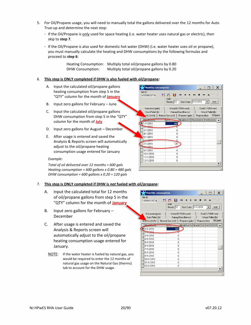
5. For Oil/Propane usage, you will need to manually total the gallons delivered over the 12 months for Auto True-up and determine the next step:
- If the Oil/Propane is only used for space heating (i.e. water heater uses natural gas or electric), then skip to step 7.
- If the Oil/Propane is also used for domestic hot water (DHW) (i.e. water heater uses oil or propane), you must manually calculate the heating and DHW consumptions by the following formulas and proceed to step 6:
Heating Consumption: Multiply total oil/propane gallons by 0.80 DHW Consumption: Multiply total oil/propane gallons by 0.20
6. This step is ONLY completed if DHW is also fueled with oil/propane:
A. Input the calculated oil/propane gallons heating consumption from step 5 in the “QTY” column for the month of January
B. Input zero gallons for February – June
C. Input the calculated oil/propane gallons DHW consumption from step 5 in the “QTY” column for the month of July
D. Input zero gallons for August – December
E. After usage is entered and saved the Analysis & Reports screen will automatically adjust to the oil/propane heating consumption usage entered for January
Example:
Total of oil delivered over 12 months = 600 gals Heating consumption = 600 gallons x 0.80 = 480 gals DHW consumption = 600 gallons x 0.20 = 120 gals
7. This step is ONLY completed if DHW is not fueled with oil/propane:
A. Input the calculated total for 12 months of oil/propane gallons from step 5 in the “QTY” column for the month of January
B. Input zero gallons for February – December
C. After usage is entered and saved the Analysis & Reports screen will automatically adjust to the oil/propane heating consumption usage entered for January.
NOTE: If the water heater is fueled by natural gas, you
would be required to enter the 12 months of natural gas usage on the Natural Gas (therms) tab to account for the DHW usage.
NJ HPwES RHA User Guide 21/90 v07.20.12
Unreliable Fuel Bill Procedure:
If the customer has not lived in the home for 12 months or the 12 months of heating fuel or electric usage does not meet the minimum guidelines noted above, do not use the Auto True-up process and proceed with the following requirements:
Do not enter any heating fuel or electric usage data in RHA Add/Analyze screens; and
RHA Building Model data entries must match the data recorded on the project’s Audit Data Collection Form; and
Work Completion application must include the usage for the months the customer has lived in the home up to 12 months; and
Work Completion application must include a note with the reason the usage was determined unreliable such as ≤ 12 months usage or ≥ 6 estimated reads; and
RHA Building Model Thermostat Settings must remain at default settings:
Heating 68-74, Setbacks 5-10 deg, Setback Periods 4-12 hrs/day, 5 days/wk Cooling 74-80, Setbacks 5-10 deg, Setback Periods 4-12 hrs/day, 5 days/wk
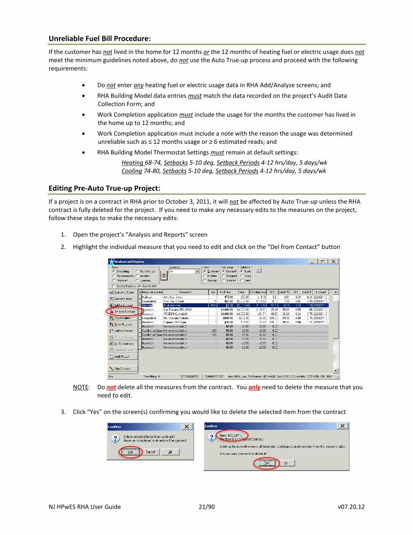
Editing Pre-Auto True-up Project:
If a project is on a contract in RHA prior to October 3, 2011, it will not be affected by Auto True-up unless the RHA contract is fully deleted for the project. If you need to make any necessary edits to the measures on the project, follow these steps to make the necessary edits:
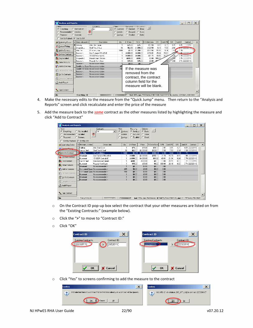
1. Open the project’s “Analysis and Reports” screen
2. Highlight the individual measure that you need to edit and click on the “Del from Contact” button
NOTE: Do not delete all the measures from the contract. You only need to delete the measure that you
need to edit. 3. Click “Yes” on the screen(s) confirming you would like to delete the selected item from the contract
NJ HPwES RHA User Guide 22/90 v07.20.12
4. Make the necessary edits to the measure from the “Quick Jump” menu. Then return to the “Analysis and
Reports” screen and click recalculate and enter the price of the measure
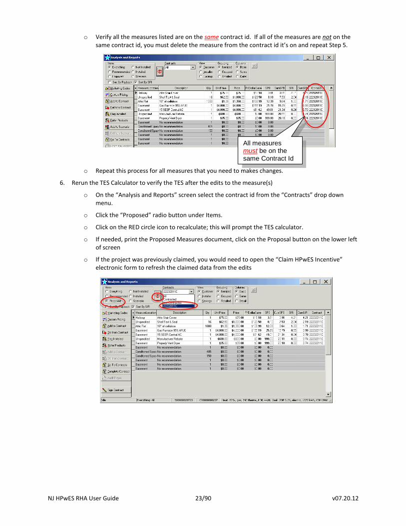
5. Add the measure back to the same contract as the other measures listed by highlighting the measure and click “Add to Contract”
o On the Contract ID pop-up box select the contract that your other measures are listed on from the “Existing Contracts:” (example below).
o Click the “>” to move to “Contract ID:”
o Click “OK”
o Click “Yes” to screens confirming to add the measure to the contract
If the measure was removed from the contract, the contract column field for the measure will be blank.
NJ HPwES RHA User Guide 23/90 v07.20.12
o Verify all the measures listed are on the same contract id. If all of the measures are not on the same contract id, you must delete the measure from the contract id it’s on and repeat Step 5.
o Repeat this process for all measures that you need to makes changes.
6. Rerun the TES Calculator to verify the TES after the edits to the measure(s)
o On the “Analysis and Reports” screen select the contract id from the “Contracts” drop down menu.
o Click the “Proposed” radio button under Items.
o Click on the RED circle icon to recalculate; this will prompt the TES calculator.
o If needed, print the Proposed Measures document, click on the Proposal button on the lower left of screen
o If the project was previously claimed, you would need to open the “Claim HPwES Incentive” electronic form to refresh the claimed data from the edits
All measures must be on the same Contract Id
NJ HPwES RHA User Guide 24/90 v07.20.12
Heating and Cooling:
Existing Equipment Efficiencies:
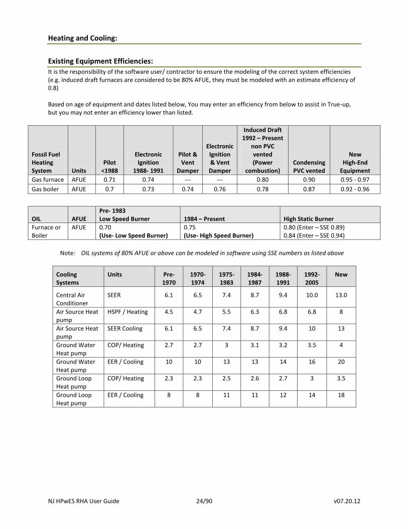
It is the responsibility of the software user/ contractor to ensure the modeling of the correct system efficiencies (e.g. induced draft furnaces are considered to be 80% AFUE, they must be modeled with an estimate efficiency of 0.8) Based on age of equipment and dates listed below, You may enter an efficiency from below to assist in True-up, but you may not enter an efficiency lower than listed.
Fossil Fuel Heating System Units
Pilot <1988
Electronic Ignition
1988- 1991
Pilot & Vent
Damper
Electronic Ignition & Vent Damper
Induced Draft 1992 – Present
non PVC vented (Power
combustion) Condensing PVC vented
New High-End
Equipment
Gas furnace AFUE 0.71 0.74 --- --- 0.80 0.90 0.95 - 0.97
Gas boiler AFUE 0.7 0.73 0.74 0.76 0.78 0.87 0.92 - 0.96
OIL AFUE Pre- 1983 Low Speed Burner 1984 – Present High Static Burner
Furnace or Boiler
AFUE
0.70 (Use- Low Speed Burner)
0.75 (Use- High Speed Burner)
0.80 (Enter – SSE 0.89) 0.84 (Enter – SSE 0.94)
Note: OIL systems of 80% AFUE or above can be modeled in software using SSE numbers as listed above
Cooling Systems
Units Pre- 1970
1970- 1974
1975- 1983
1984- 1987
1988- 1991
1992- 2005
New
Central Air Conditioner
SEER 6.1 6.5 7.4 8.7 9.4 10.0 13.0
Air Source Heat pump
HSPF / Heating 4.5 4.7 5.5 6.3 6.8 6.8 8
Air Source Heat pump
SEER Cooling 6.1 6.5 7.4 8.7 9.4 10 13
Ground Water Heat pump
COP/ Heating 2.7 2.7 3 3.1 3.2 3.5 4
Ground Water Heat pump
EER / Cooling 10 10 13 13 14 16 20
Ground Loop Heat pump
COP/ Heating 2.3 2.3 2.5 2.6 2.7 3 3.5
Ground Loop Heat pump
EER / Cooling 8 8 11 11 12 14 18
NJ HPwES RHA User Guide 25/90 v07.20.12
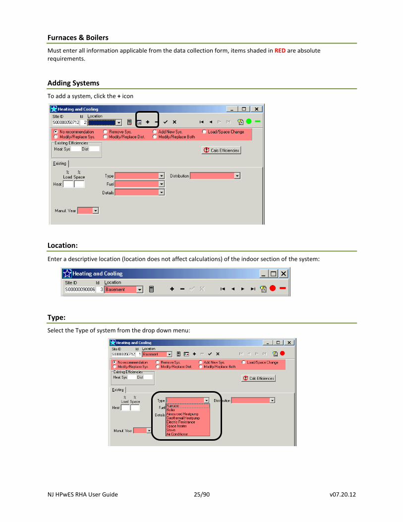
Furnaces & Boilers
Must enter all information applicable from the data collection form, items shaded in RED are absolute requirements.
Adding Systems
To add a system, click the + icon
Location:
Enter a descriptive location (location does not affect calculations) of the indoor section of the system:
Type:
Select the Type of system from the drop down menu:
NJ HPwES RHA User Guide 26/90 v07.20.12
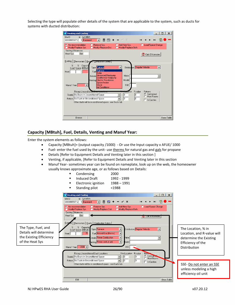
Selecting the type will populate other details of the system that are applicable to the system, such as ducts for systems with ducted distribution:
Capacity [MBtuh], Fuel, Details, Venting and Manuf Year:
Enter the system elements as follows:
Capacity [MBtuh]= (output capacity /1000) - Or use the Input capacity x AFUE/ 1000
Fuel- enter the fuel used by the unit- use therms for natural gas and gals for propane
Details [Refer to Equipment Details and Venting later in this section ]
Venting, if applicable, [Refer to Equipment Details and Venting later in this section
Manuf Year- sometimes year can be found on nameplate, look up on the web, the homeowner usually knows approximate age, or as follows based on Details:
Condensing 2000 Induced Draft 1992 - 1999 Electronic ignition 1988 – 1991 Standing pilot <1988
The Type, Fuel, and Details will determine the Existing Efficiency of the Heat Sys
The Location, % in Location, and R-value will determine the Existing Efficiency of the Distribution
SSE- Do not enter an SSE unless modeling a high efficiency oil unit
NJ HPwES RHA User Guide 27/90 v07.20.12
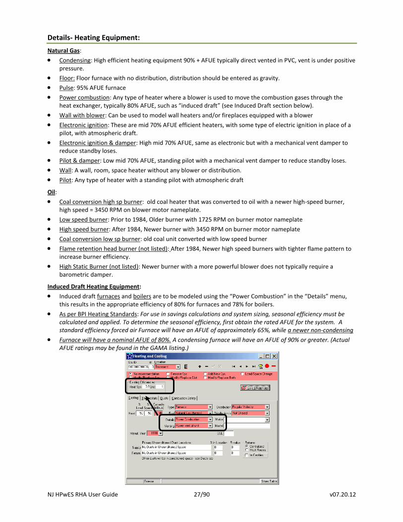
Details- Heating Equipment:
Natural Gas:
Condensing: High efficient heating equipment 90% + AFUE typically direct vented in PVC, vent is under positive pressure.
Floor: Floor furnace with no distribution, distribution should be entered as gravity.
Pulse: 95% AFUE furnace
Power combustion: Any type of heater where a blower is used to move the combustion gases through the heat exchanger, typically 80% AFUE, such as “induced draft” (see Induced Draft section below).
Wall with blower: Can be used to model wall heaters and/or fireplaces equipped with a blower
Electronic ignition: These are mid 70% AFUE efficient heaters, with some type of electric ignition in place of a pilot, with atmospheric draft.
Electronic ignition & damper: High mid 70% AFUE, same as electronic but with a mechanical vent damper to reduce standby loses.
Pilot & damper: Low mid 70% AFUE, standing pilot with a mechanical vent damper to reduce standby loses.
Wall: A wall, room, space heater without any blower or distribution.
Pilot: Any type of heater with a standing pilot with atmospheric draft
Oil:
Coal conversion high sp burner: old coal heater that was converted to oil with a newer high-speed burner, high speed = 3450 RPM on blower motor nameplate.
Low speed burner: Prior to 1984, Older burner with 1725 RPM on burner motor nameplate
High speed burner: After 1984, Newer burner with 3450 RPM on burner motor nameplate
Coal conversion low sp burner: old coal unit converted with low speed burner
Flame retention head burner (not listed): After 1984, Newer high speed burners with tighter flame pattern to increase burner efficiency.
High Static Burner (not listed): Newer burner with a more powerful blower does not typically require a barometric damper.
Induced Draft Heating Equipment:
Induced draft furnaces and boilers are to be modeled using the “Power Combustion” in the “Details” menu, this results in the appropriate efficiency of 80% for furnaces and 78% for boilers.
As per BPI Heating Standards: For use in savings calculations and system sizing, seasonal efficiency must be calculated and applied. To determine the seasonal efficiency, first obtain the rated AFUE for the system. A standard efficiency forced air Furnace will have an AFUE of approximately 65%, while a newer non-condensing
Furnace will have a nominal AFUE of 80%. A condensing furnace will have an AFUE of 90% or greater. (Actual AFUE ratings may be found in the GAMA listing.)

NJ HPwES RHA User Guide 28/90 v07.20.12
%Load & % Space:
Enter the percentage of the load (%Load) this system will satisfy and the percentage of floor area (%Space) serviced by the distribution system:
% Load is the approximate percentage of the total house load the system heats or cools. A default of 100% if one system, 50%/50% if two systems, and 33%/33%/34% if three systems, etc., based on % of total capacity of all units (see Capacity Weighted below), or based Manual J calculations are all acceptable methods to determine % Load.
% Space is the approximate percentage of the total house square feet the system heats or cools. Using the approx % of square feet or the same number as % Load are acceptable methods to determine % Space.
Capacity Weighted % Load: Total the capacities of all heating equipment (or cooling equipment) then divide the capacity of a single unit by the total capacity, this is the % load that should be entered for that system, repeat this for each unit.
Example: House with two (2) existing furnaces: Furnace A capacity = 60 mbtu Furnace B capacity = 40 mbtu Total capacity = 100 mbtu
Enter the % Load for furnace as 60/100 = 60% Load
Enter the % Load for furnace B as 40/100 = 40% Load
NJ HPwES RHA User Guide 29/90 v07.20.12
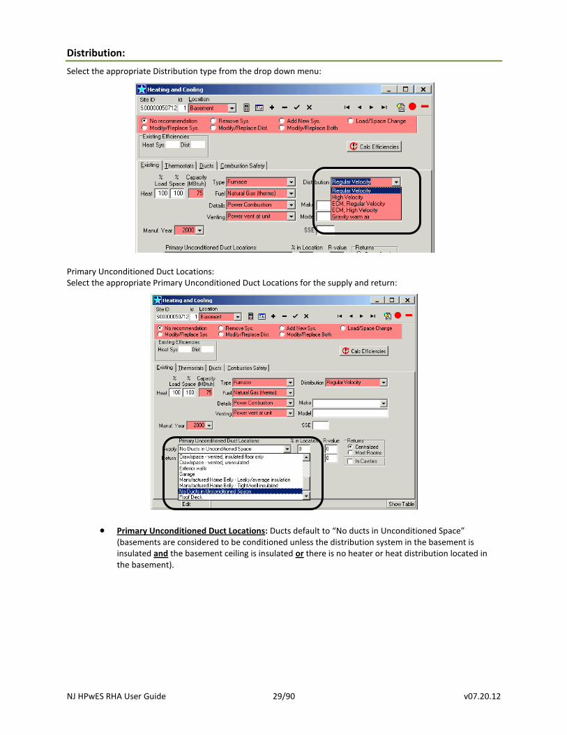
Distribution:
Select the appropriate Distribution type from the drop down menu:
Primary Unconditioned Duct Locations: Select the appropriate Primary Unconditioned Duct Locations for the supply and return:
Primary Unconditioned Duct Locations: Ducts default to “No ducts in Unconditioned Space” (basements are considered to be conditioned unless the distribution system in the basement is insulated and the basement ceiling is insulated or there is no heater or heat distribution located in the basement).
NJ HPwES RHA User Guide 30/90 v07.20.12
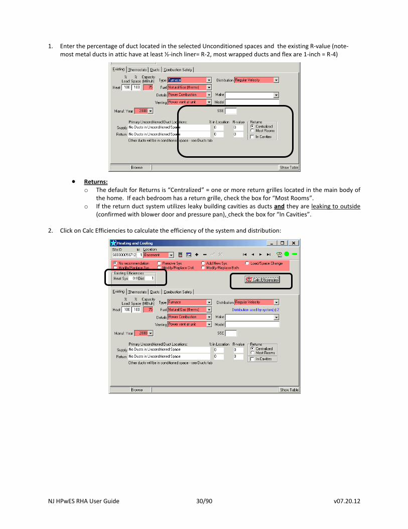
1. Enter the percentage of duct located in the selected Unconditioned spaces and the existing R-value (note-
most metal ducts in attic have at least ½-inch liner= R-2, most wrapped ducts and flex are 1-inch = R-4)
Returns: o The default for Returns is “Centralized” = one or more return grilles located in the main body of
the home. If each bedroom has a return grille, check the box for “Most Rooms”. o If the return duct system utilizes leaky building cavities as ducts and they are leaking to outside
(confirmed with blower door and pressure pan), check the box for “In Cavities”.
2. Click on Calc Efficiencies to calculate the efficiency of the system and distribution:
NJ HPwES RHA User Guide 31/90 v07.20.12
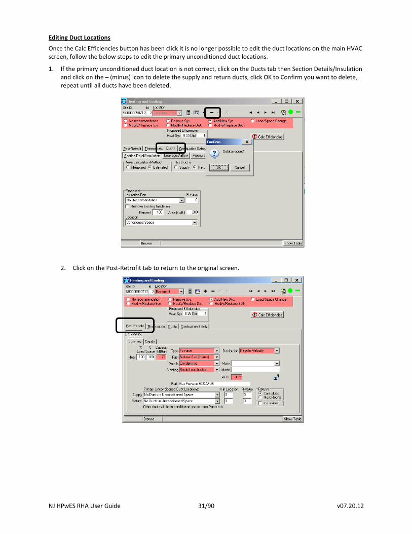
Editing Duct Locations
Once the Calc Efficiencies button has been click it is no longer possible to edit the duct locations on the main HVAC screen, follow the below steps to edit the primary unconditioned duct locations.
1. If the primary unconditioned duct location is not correct, click on the Ducts tab then Section Details/Insulation and click on the – (minus) icon to delete the supply and return ducts, click OK to Confirm you want to delete, repeat until all ducts have been deleted.
2. Click on the Post-Retrofit tab to return to the original screen.
NJ HPwES RHA User Guide 32/90 v07.20.12
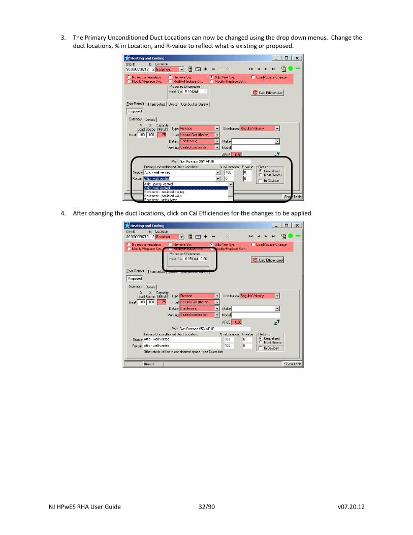
3. The Primary Unconditioned Duct Locations can now be changed using the drop down menus. Change the duct locations, % in Location, and R-value to reflect what is existing or proposed.
4. After changing the duct locations, click on Cal Efficiencies for the changes to be applied
NJ HPwES RHA User Guide 33/90 v07.20.12
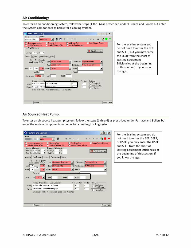
Air Conditioning:
To enter an air conditioning system, follow the steps (1 thru 6) as prescribed under Furnace and Boilers but enter the system components as below for a cooling system.
Air Sourced Heat Pump:
To enter an air source heat pump system, follow the steps (1 thru 6) as prescribed under Furnace and Boilers but enter the system components as below for a heating/cooling system.
For the Existing system you do not need to enter the EER, SEER, or HSPF, you may enter the HSPF and SEER from the chart of Existing Equipment Efficiencies at the beginning of this section, if you know the age.
For the existing system you do not need to enter the EER and SEER, but you may enter the SEER from the chart of Existing Equipment Efficiencies at the beginning of this section, if you know the age.
NJ HPwES RHA User Guide 34/90 v07.20.12
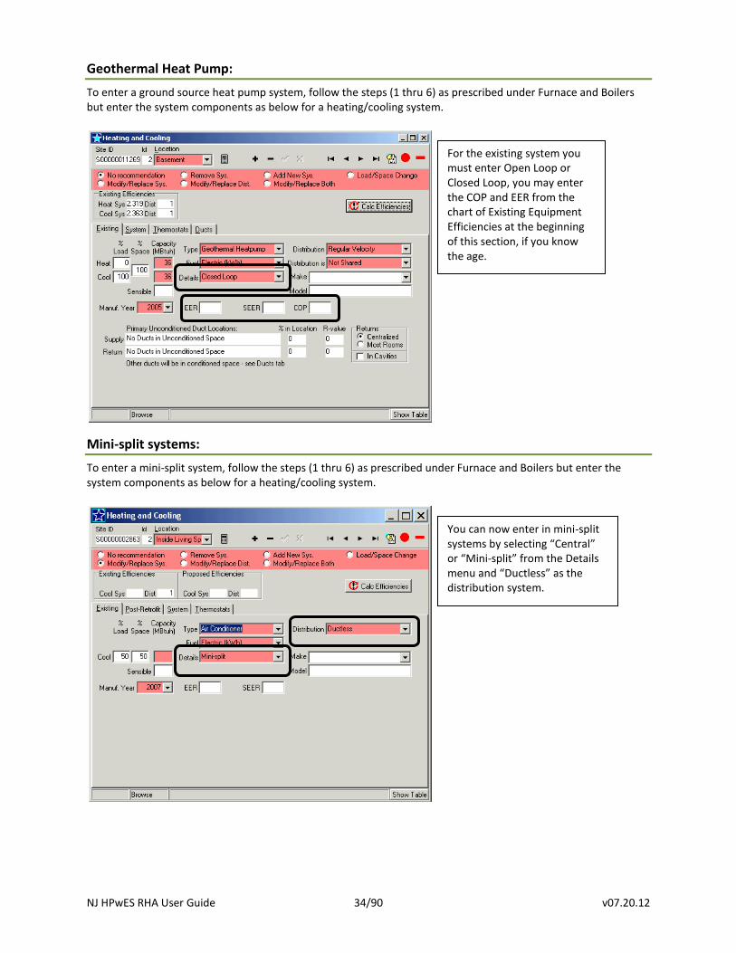
Geothermal Heat Pump:
To enter a ground source heat pump system, follow the steps (1 thru 6) as prescribed under Furnace and Boilers but enter the system components as below for a heating/cooling system.
Mini-split systems:
To enter a mini-split system, follow the steps (1 thru 6) as prescribed under Furnace and Boilers but enter the system components as below for a heating/cooling system.
For the existing system you must enter Open Loop or Closed Loop, you may enter the COP and EER from the chart of Existing Equipment Efficiencies at the beginning of this section, if you know the age.
You can now enter in mini-split systems by selecting “Central” or “Mini-split” from the Details menu and “Ductless” as the distribution system.
NJ HPwES RHA User Guide 35/90 v07.20.12
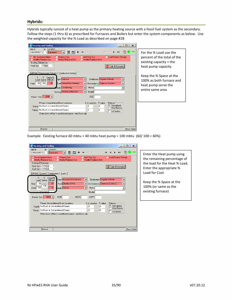
Hybrids:
Hybrids typically consist of a heat pump as the primary heating source with a fossil fuel system as the secondary. Follow the steps (1 thru 6) as prescribed for Furnaces and Boilers but enter the system components as below. Use the weighted capacity for the % Load as described on page #28
Example: Existing furnace 60 mbtu + 40 mbtu heat pump = 100 mbtu (60/ 100 = 60%)
For the % Load use the percent of the total of the existing capacity + the heat pump capacity. Keep the % Space at the 100% as both furnace and heat pump serve the entire same area
Enter the Heat pump using the remaining percentage of the load for the Heat % Load. Enter the appropriate % Load for Cool. Keep the % Space at the 100% (or same as the existing furnace)
NJ HPwES RHA User Guide 36/90 v07.20.12
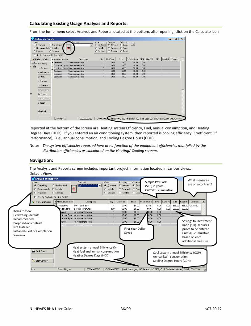
Calculating Existing Usage Analysis and Reports:
From the Jump menu select Analysis and Reports located at the bottom, after opening, click on the Calculate Icon
Reported at the bottom of the screen are Heating system Efficiency, Fuel, annual consumption, and Heating Degree Days (HDD). If you entered an air conditioning system, then reported is cooling efficiency (Coefficient Of Performance), Fuel, annual consumption, and Cooling Degree Hours (CDH).
Note: The system efficiencies reported here are a function of the equipment efficiencies multiplied by the distribution efficiencies as calculated on the Heating/ Cooling screens.
Navigation:
The Analysis and Reports screen includes important project information located in various views. Default View:
What measures are on a contract?
Savings to Investment Ratio (SIR)- requires prices to be entered. CumSIR- cumulative based on each additional measure
First Year Dollar Saved
Simple Pay Back (SPB) in years. CumSPB- cumulative
Items to view: Everything- default Recommended Proposed-on contract Not Installed Installed- Cert of Completion Scenario
Heat system annual Efficiency (%) Heat fuel and annual consumption Heating Degree Days (HDD)
Cool system annual Efficiency (COP) Annual kWh consumption Cooling Degree Hours (CDH)
NJ HPwES RHA User Guide 37/90 v07.20.12
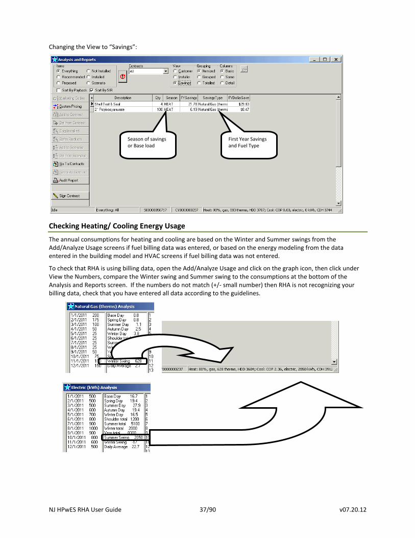
Changing the View to “Savings”:
Checking Heating/ Cooling Energy Usage
The annual consumptions for heating and cooling are based on the Winter and Summer swings from the Add/Analyze Usage screens if fuel billing data was entered, or based on the energy modeling from the data entered in the building model and HVAC screens if fuel billing data was not entered.
To check that RHA is using billing data, open the Add/Analyze Usage and click on the graph icon, then click under View the Numbers, compare the Winter swing and Summer swing to the consumptions at the bottom of the Analysis and Reports screen. If the numbers do not match (+/- small number) then RHA is not recognizing your billing data, check that you have entered all data according to the guidelines.
Season of savings or Base load
First Year Savings and Fuel Type
NJ HPwES RHA User Guide 38/90 v07.20.12
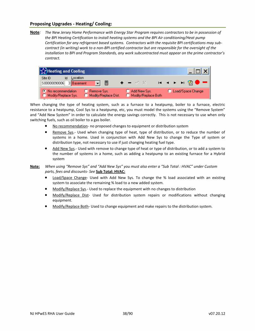
Proposing Upgrades - Heating/ Cooling:
Note: The New Jersey Home Performance with Energy Star Program requires contractors to be in possession of
the BPI Heating Certification to install heating systems and the BPI Air conditioning/Heat pump Certification for any refrigerant based systems. Contractors with the requisite BPI certifications may sub-contract (in writing) work to a non-BPI certified contractor but are responsible for the oversight of the installation to BPI and Program Standards, any work subcontracted must appear on the prime contractor’s contract.
When changing the type of heating system, such as a furnace to a heatpump, boiler to a furnace, electric resistance to a heatpump, Cool Sys to a heatpump, etc, you must model the systems using the “Remove System” and “Add New System” in order to calculate the energy savings correctly. This is not necessary to use when only switching fuels, such as oil boiler to a gas boiler.
No recommendation- no proposed changes to equipment or distribution system
Remove Sys.- Used when changing type of heat, type of distribution, or to reduce the number of systems in a home. Used in conjunction with Add New Sys to change the Type of system or distribution type, not necessary to use if just changing heating fuel type.
Add New Sys.- Used with remove to change type of heat or type of distribution, or to add a system to the number of systems in a home, such as adding a heatpump to an existing furnace for a Hybrid system
Note: When using “Remove Sys” and “Add New Sys” you must also enter a “Sub Total : HVAC” under Custom parts, fees and discounts- See Sub Total: HVAC:
Load/Space Change- Used with Add New Sys. To change the % load associated with an existing system to associate the remaining % load to a new added system.
Modify/Replace Sys.- Used to replace the equipment with no changes to distribution
Modify/Replace Dist- Used for distribution system repairs or modifications without changing equipment.
Modify/Replace Both- Used to change equipment and make repairs to the distribution system.
NJ HPwES RHA User Guide 39/90 v07.20.12
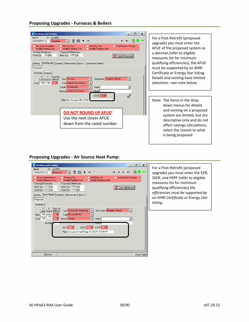
Proposing Upgrades - Furnaces & Boilers
Proposing Upgrades - Air Source Heat Pump:
For a Post-Retrofit (proposed upgrade) you must enter the EER, SEER, and HSPF (refer to eligible measures list for minimum qualifying efficiencies) the efficiencies must be supported by an AHRI Certificate or Energy Star listing.
For a Post-Retrofit (proposed upgrade) you must enter the AFUE of the proposed system as a decimal (refer to eligible measures list for minimum qualifying efficiencies), the AFUE must be supported by an AHRI Certificate or Energy Star listing. Details and venting have limited selections –see note below
DO NOT ROUND UP AFUE! Use the next closer AFUE down from the rated number.
Note: The items in the drop down menus for details and venting on a proposed system are limited, but are descriptive only and do not affect savings calculations, select the closest to what is being proposed
NJ HPwES RHA User Guide 40/90 v07.20.12
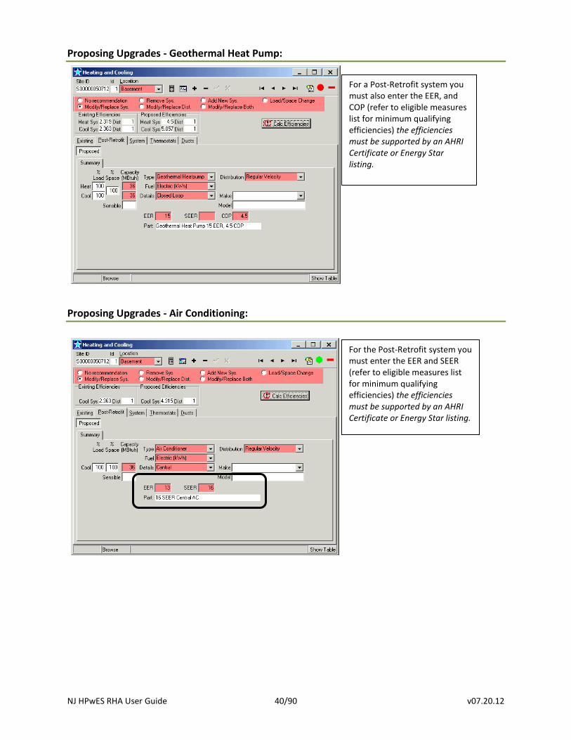
Proposing Upgrades - Geothermal Heat Pump:
Proposing Upgrades - Air Conditioning:
For a Post-Retrofit system you must also enter the EER, and COP (refer to eligible measures list for minimum qualifying efficiencies) the efficiencies must be supported by an AHRI Certificate or Energy Star listing.
For the Post-Retrofit system you must enter the EER and SEER (refer to eligible measures list for minimum qualifying efficiencies) the efficiencies must be supported by an AHRI Certificate or Energy Star listing.
NJ HPwES RHA User Guide 41/90 v07.20.12
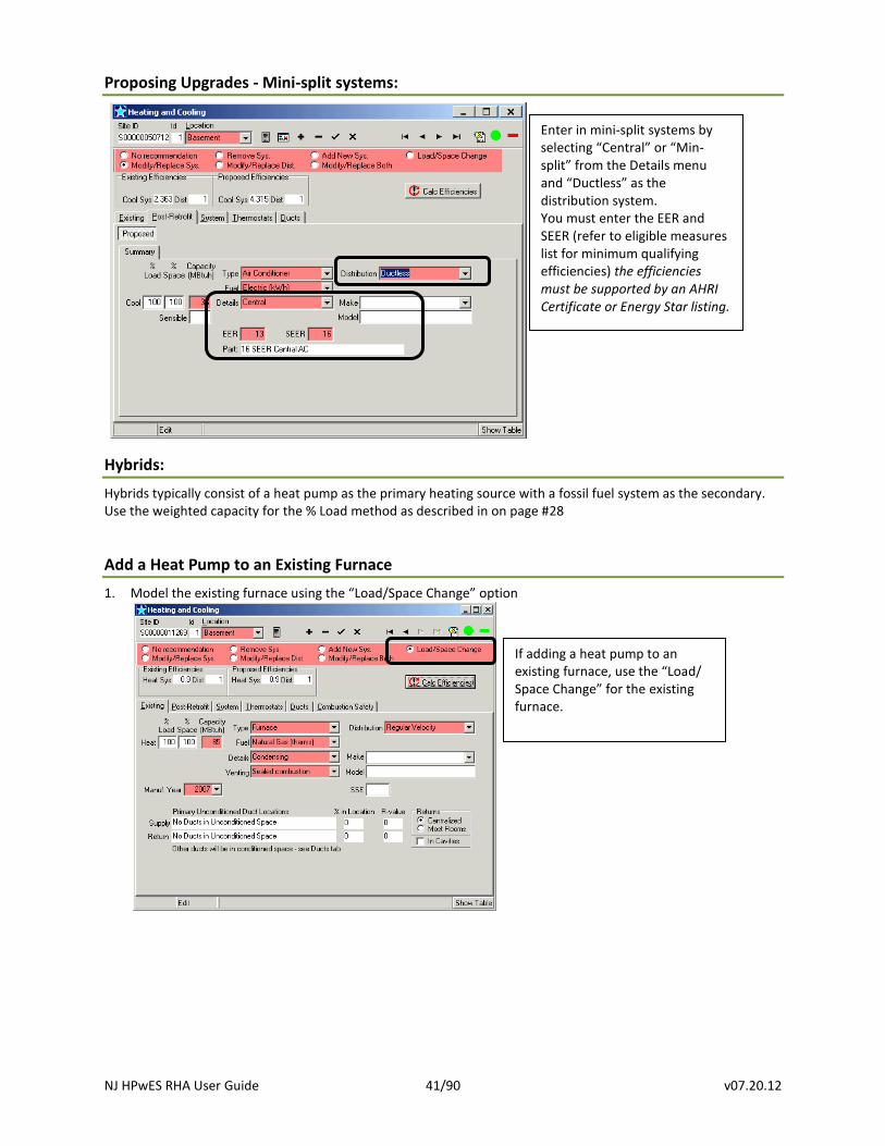
Proposing Upgrades - Mini-split systems:
Hybrids:
Hybrids typically consist of a heat pump as the primary heating source with a fossil fuel system as the secondary. Use the weighted capacity for the % Load method as described in on page #28
Add a Heat Pump to an Existing Furnace
1. Model the existing furnace using the “Load/Space Change” option
If adding a heat pump to an existing furnace, use the “Load/ Space Change” for the existing furnace.
Enter in mini-split systems by selecting “Central” or “Min-split” from the Details menu and “Ductless” as the distribution system. You must enter the EER and SEER (refer to eligible measures list for minimum qualifying efficiencies) the efficiencies must be supported by an AHRI Certificate or Energy Star listing.
NJ HPwES RHA User Guide 42/90 v07.20.12
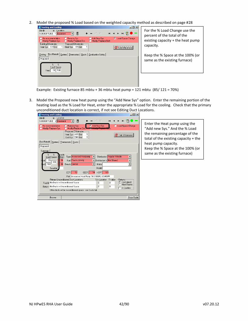
2. Model the proposed % Load based on the weighted capacity method as described on page #28
Example: Existing furnace 85 mbtu + 36 mbtu heat pump = 121 mbtu (85/ 121 = 70%)
3. Model the Proposed new heat pump using the “Add New Sys” option. Enter the remaining portion of the
heating load as the % Load for Heat, enter the appropriate % Load for the cooling. Check that the primary unconditioned duct location is correct, if not see Editing Duct Locations.
For the % Load Change use the percent of the total of the existing capacity + the heat pump capacity. Keep the % Space at the 100% (or same as the existing furnace)
Enter the Heat pump using the “Add new Sys.” And the % Load the remaining percentage of the total of the existing capacity + the heat pump capacity. Keep the % Space at the 100% (or same as the existing furnace)
NJ HPwES RHA User Guide 43/90 v07.20.12
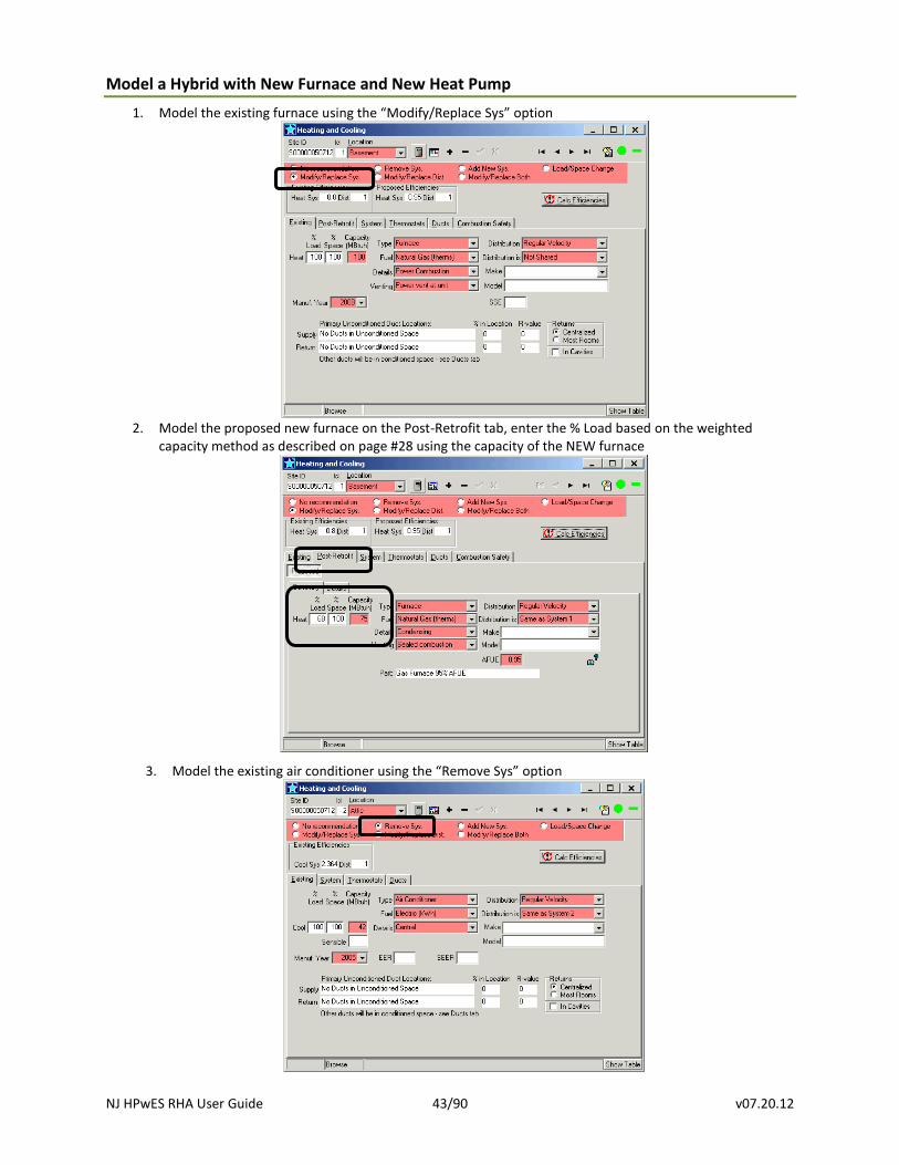
Model a Hybrid with New Furnace and New Heat Pump
1. Model the existing furnace using the “Modify/Replace Sys” option
2. Model the proposed new furnace on the Post-Retrofit tab, enter the % Load based on the weighted
capacity method as described on page #28 using the capacity of the NEW furnace
3. Model the existing air conditioner using the “Remove Sys” option
NJ HPwES RHA User Guide 44/90 v07.20.12
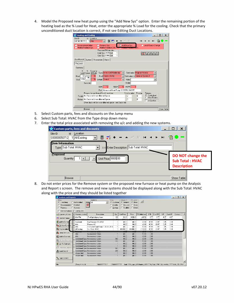
4. Model the Proposed new heat pump using the “Add New Sys” option. Enter the remaining portion of the heating load as the % Load for Heat, enter the appropriate % Load for the cooling. Check that the primary unconditioned duct location is correct, if not see Editing Duct Locations.
5. Select Custom parts, fees and discounts on the Jump menu 6. Select Sub Total: HVAC from the Type drop down menu 7. Enter the total price associated with removing the a/c and adding the new systems.
8. Do not enter prices for the Remove system or the proposed new furnace or heat pump on the Analysis
and Report s screen. The remove and new systems should be displayed along with the Sub Total: HVAC along with the price and they should be listed together
DO NOT change the Sub Total : HVAC Description
NJ HPwES RHA User Guide 45/90 v07.20.12
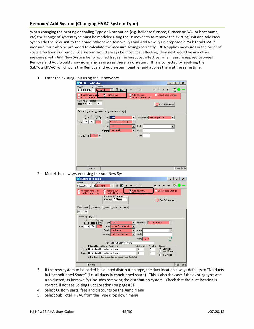
Remove/ Add System [Changing HVAC System Type}
When changing the heating or cooling Type or Distribution (e.g. boiler to furnace, furnace or A/C to heat pump, etc) the change of system type must be modeled using the Remove Sys to remove the existing unit and Add New Sys to add the new unit to the home. Whenever Remove Sys and Add New Sys is proposed a “SubTotal:HVAC” measure must also be proposed to calculate the measure savings correctly. RHA applies measures in the order of costs effectiveness, removing a system would always be most cost effective, then next would be any other measures, with Add New System being applied last as the least cost effective , any measure applied between Remove and Add would show no energy savings as there is no system. This is corrected by applying the SubTotal:HVAC, which pulls the Remove and Add system together and applies them at the same time.
1. Enter the existing unit using the Remove Sys.
2. Model the new system using the Add New Sys.
3. If the new system to be added is a ducted distribution type, the duct location always defaults to “No ducts
in Unconditioned Space” (i.e. all ducts in conditioned space). This is also the case if the existing type was also ducted, as Remove Sys includes removing the distribution system. Check that the duct location is correct, if not see Editing Duct Locations on page #31
4. Select Custom parts, fees and discounts on the Jump menu 5. Select Sub Total: HVAC from the Type drop down menu
NJ HPwES RHA User Guide 46/90 v07.20.12
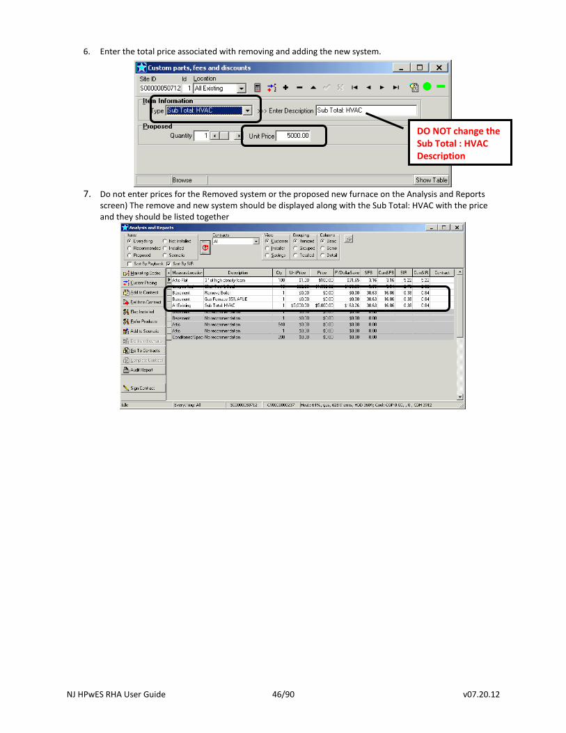
6. Enter the total price associated with removing and adding the new system.
7. Do not enter prices for the Removed system or the proposed new furnace on the Analysis and Reports
screen) The remove and new system should be displayed along with the Sub Total: HVAC with the price and they should be listed together
DO NOT change the Sub Total : HVAC Description
NJ HPwES RHA User Guide 47/90 v07.20.12
Ducts:
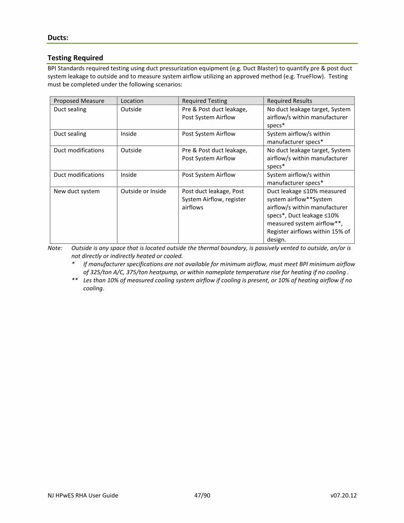
Testing Required
BPI Standards required testing using duct pressurization equipment (e.g. Duct Blaster) to quantify pre & post duct system leakage to outside and to measure system airflow utilizing an approved method (e.g. TrueFlow). Testing must be completed under the following scenarios:
Proposed Measure Location Required Testing Required Results
Duct sealing Outside Pre & Post duct leakage, Post System Airflow
No duct leakage target, System airflow/s within manufacturer specs*
Duct sealing Inside Post System Airflow System airflow/s within manufacturer specs*
Duct modifications Outside Pre & Post duct leakage, Post System Airflow
No duct leakage target, System airflow/s within manufacturer specs*
Duct modifications Inside Post System Airflow System airflow/s within manufacturer specs*
New duct system Outside or Inside Post duct leakage, Post System Airflow, register airflows
Duct leakage ≤10% measured system airflow**System airflow/s within manufacturer specs*, Duct leakage ≤10% measured system airflow**, Register airflows within 15% of design.
Note: Outside is any space that is located outside the thermal boundary, is passively vented to outside, an/or is not directly or indirectly heated or cooled. * If manufacturer specifications are not available for minimum airflow, must meet BPI minimum airflow
of 325/ton A/C, 375/ton heatpump, or within nameplate temperature rise for heating if no cooling . ** Les than 10% of measured cooling system airflow if cooling is present, or 10% of heating airflow if no
cooling.
NJ HPwES RHA User Guide 48/90 v07.20.12
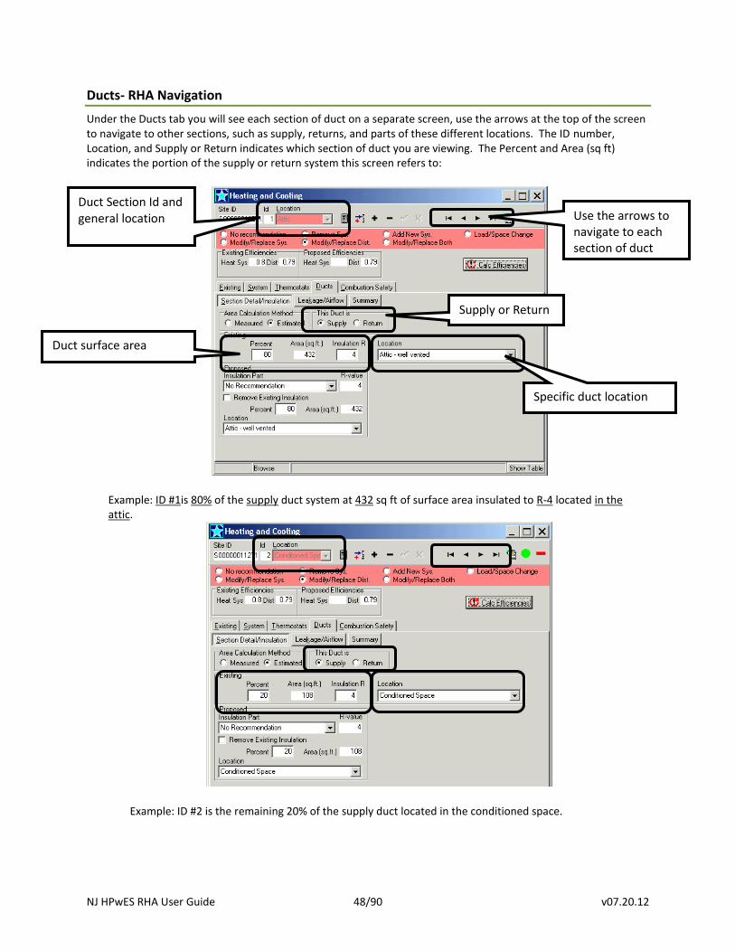
Ducts- RHA Navigation
Under the Ducts tab you will see each section of duct on a separate screen, use the arrows at the top of the screen to navigate to other sections, such as supply, returns, and parts of these different locations. The ID number, Location, and Supply or Return indicates which section of duct you are viewing. The Percent and Area (sq ft) indicates the portion of the supply or return system this screen refers to:
Example: ID #1is 80% of the supply duct system at 432 sq ft of surface area insulated to R-4 located in the attic.
Example: ID #2 is the remaining 20% of the supply duct located in the conditioned space.
Supply or Return
Use the arrows to navigate to each section of duct
Specific duct location
Duct surface area
Duct Section Id and general location
NJ HPwES RHA User Guide 49/90 v07.20.12
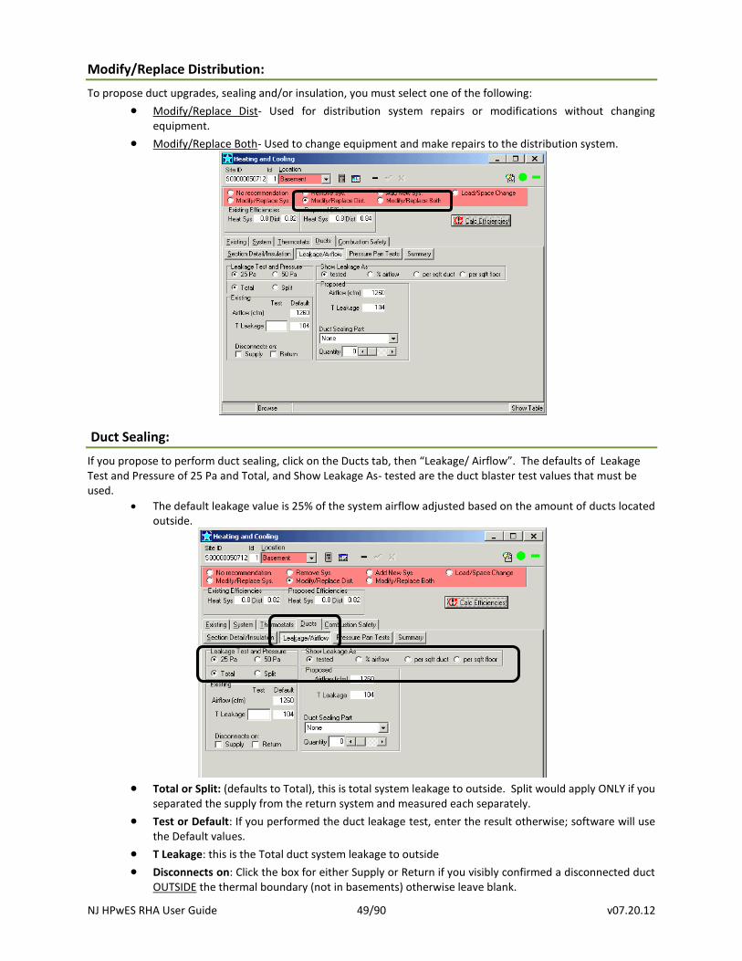
Modify/Replace Distribution:
To propose duct upgrades, sealing and/or insulation, you must select one of the following:
Modify/Replace Dist- Used for distribution system repairs or modifications without changing equipment.
Modify/Replace Both- Used to change equipment and make repairs to the distribution system.
Duct Sealing:
If you propose to perform duct sealing, click on the Ducts tab, then “Leakage/ Airflow”. The defaults of Leakage Test and Pressure of 25 Pa and Total, and Show Leakage As- tested are the duct blaster test values that must be used.
The default leakage value is 25% of the system airflow adjusted based on the amount of ducts located outside.
Total or Split: (defaults to Total), this is total system leakage to outside. Split would apply ONLY if you
separated the supply from the return system and measured each separately.
Test or Default: If you performed the duct leakage test, enter the result otherwise; software will use the Default values.
T Leakage: this is the Total duct system leakage to outside
Disconnects on: Click the box for either Supply or Return if you visibly confirmed a disconnected duct OUTSIDE the thermal boundary (not in basements) otherwise leave blank.
NJ HPwES RHA User Guide 50/90 v07.20.12
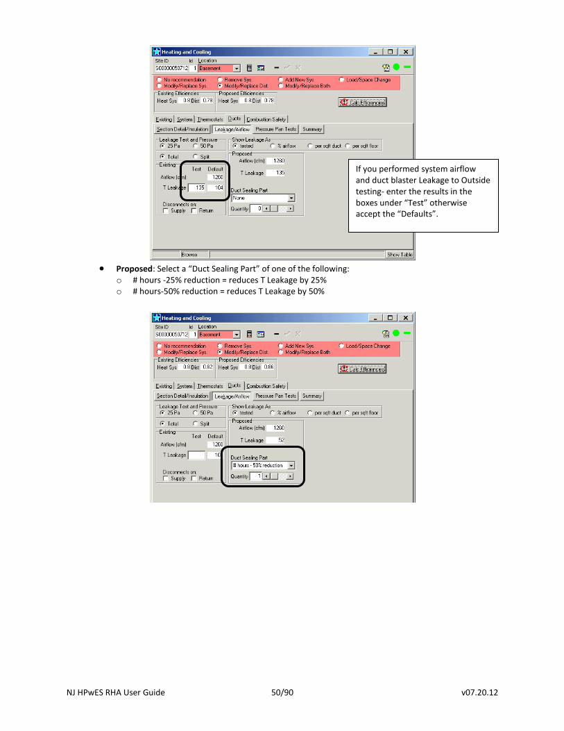
Proposed: Select a “Duct Sealing Part” of one of the following:
o # hours -25% reduction = reduces T Leakage by 25% o # hours-50% reduction = reduces T Leakage by 50%
If you performed system airflow and duct blaster Leakage to Outside testing- enter the results in the boxes under “Test” otherwise accept the “Defaults”.
NJ HPwES RHA User Guide 51/90 v07.20.12
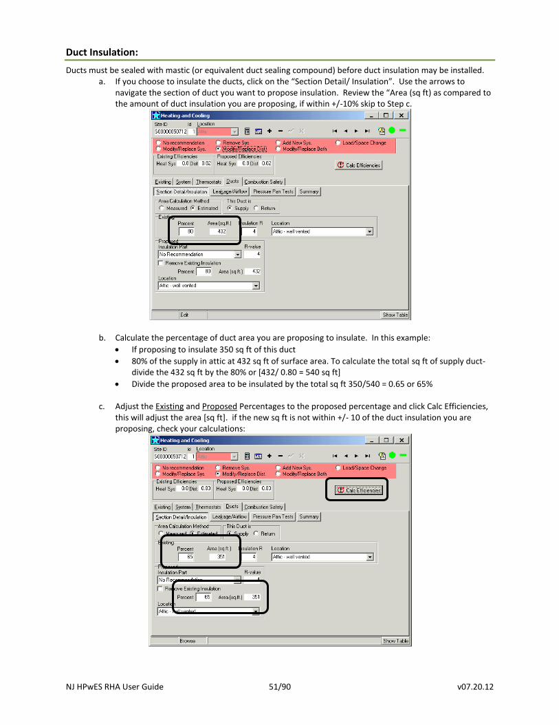
Duct Insulation:
Ducts must be sealed with mastic (or equivalent duct sealing compound) before duct insulation may be installed. a. If you choose to insulate the ducts, click on the “Section Detail/ Insulation”. Use the arrows to
navigate the section of duct you want to propose insulation. Review the “Area (sq ft) as compared to the amount of duct insulation you are proposing, if within +/-10% skip to Step c.
b. Calculate the percentage of duct area you are proposing to insulate. In this example:
If proposing to insulate 350 sq ft of this duct
80% of the supply in attic at 432 sq ft of surface area. To calculate the total sq ft of supply duct- divide the 432 sq ft by the 80% or [432/ 0.80 = 540 sq ft]
Divide the proposed area to be insulated by the total sq ft 350/540 = 0.65 or 65%
c. Adjust the Existing and Proposed Percentages to the proposed percentage and click Calc Efficiencies, this will adjust the area [sq ft]. if the new sq ft is not within +/- 10 of the duct insulation you are proposing, check your calculations:
NJ HPwES RHA User Guide 52/90 v07.20.12
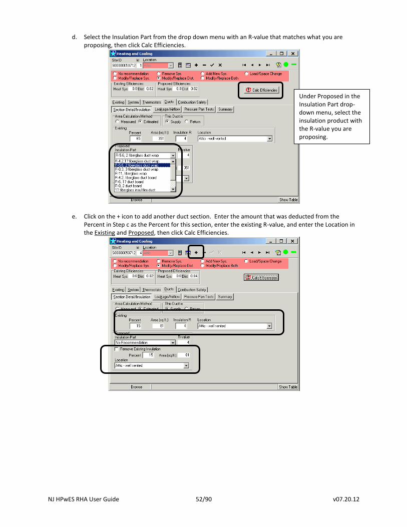
d. Select the Insulation Part from the drop down menu with an R-value that matches what you are proposing, then click Calc Efficiencies.
e. Click on the + icon to add another duct section. Enter the amount that was deducted from the
Percent in Step c as the Percent for this section, enter the existing R-value, and enter the Location in the Existing and Proposed, then click Calc Efficiencies.
Under Proposed in the Insulation Part drop-down menu, select the insulation product with the R-value you are proposing.
NJ HPwES RHA User Guide 53/90 v07.20.12
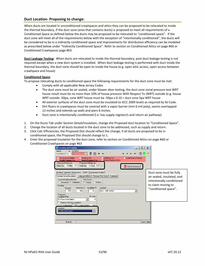
Duct Location- Proposing to change:
When ducts are located in unconditioned crawlspaces and attics they can be proposed to be relocated to inside the thermal boundary, if the duct zone (area that contains ducts) is proposed to meet all requirements of a Conditioned Space as defined below the ducts may be proposed to be relocated to “conditioned space”. If the duct zone will meet all of the requirements below with the exception of “intentionally conditioned”, the ducts will be considered to be in a indirectly conditioned space and improvements for distribution efficiency can be modeled as prescribed below under “Indirectly Conditioned Space”. Refer to section on Conditioned Attics on page #60 or Conditioned Crawlspaces page #63. Duct Leakage Testing: When ducts are relocated to inside the thermal boundary, post duct leakage testing is not required except when a new duct system is installed. When duct leakage testing is performed with duct inside the thermal boundary, the duct zone should be open to inside the house (e.g. open attic access, open access between crawlspace and house)
Conditioned Space: To propose relocating ducts to conditioned space the following requirements for the duct zone must be met:
Comply with all applicable New Jersey Codes
The duct zone must be air sealed, under blower door testing, the duct zone zonal pressure test WRT house result must be no more than 10% of house pressure With Respect To (WRT) outside (e.g. house WRT outside -50pa, zone WRT house must be -50pa x 0.10 = duct zone 5pa WRT house
All exterior surfaces of the duct zone must be insulated to IECC 2009 levels as required by NJ Code.
Dirt floors in crawlspaces must be covered with a vapor barrier (min 6-mil poly), seems overlapped 12-inches and extends up walls and piers 6-inches.
Duct zone is intentionally conditioned (i.e. has supply register/s and return air pathway)
1. On the Ducts Tab under Section Detail/Insulation, change the Proposed duct location to “Conditioned Space”. 2. Change the location of all ducts located in the duct zone to be addressed, such as supply and return. 3. Click Calc Efficiencies, the Proposed Dist should reflect the change, if all ducts are proposed to be in
conditioned space, the Proposed Dist should change to 1. 4. Enter the proposed insulation for the duct zone, refer to section on Conditioned Attics on page #60 or
Conditioned Crawlspaces on page #63
Duct zone must be fully air sealed, insulated, and intentionally conditioned to claim moving to “conditioned space”.
NJ HPwES RHA User Guide 54/90 v07.20.12
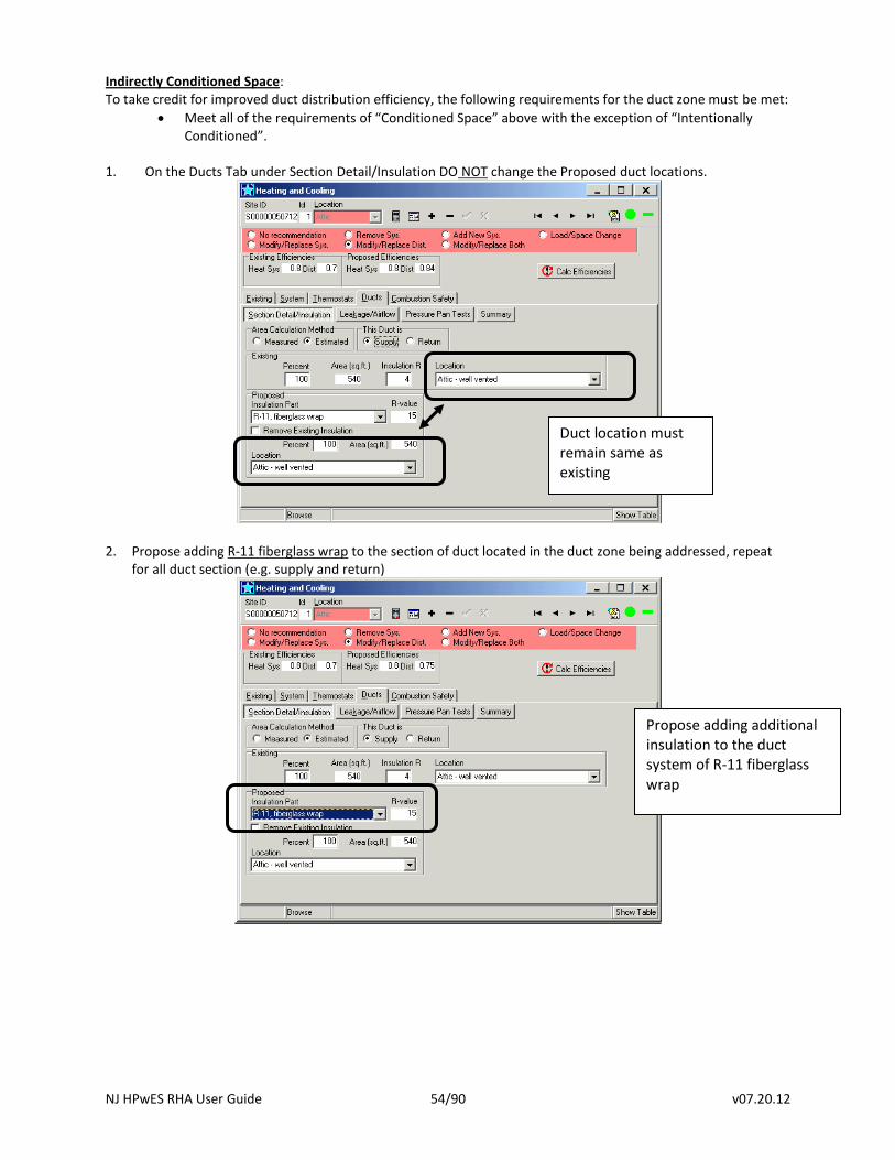
Indirectly Conditioned Space: To take credit for improved duct distribution efficiency, the following requirements for the duct zone must be met:
Meet all of the requirements of “Conditioned Space” above with the exception of “Intentionally Conditioned”.
1. On the Ducts Tab under Section Detail/Insulation DO NOT change the Proposed duct locations.
2. Propose adding R-11 fiberglass wrap to the section of duct located in the duct zone being addressed, repeat for all duct section (e.g. supply and return)
Propose adding additional insulation to the duct system of R-11 fiberglass wrap
Duct location must remain same as existing
NJ HPwES RHA User Guide 55/90 v07.20.12
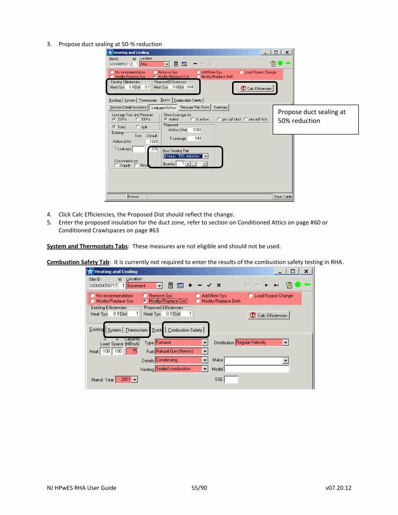
3. Propose duct sealing at 50-% reduction
4. Click Calc Efficiencies, the Proposed Dist should reflect the change. 5. Enter the proposed insulation for the duct zone, refer to section on Conditioned Attics on page #60 or
Conditioned Crawlspaces on page #63
System and Thermostats Tabs: These measures are not eligible and should not be used. Combustion Safety Tab: It is currently not required to enter the results of the combustion safety testing in RHA.
Propose duct sealing at 50% reduction
NJ HPwES RHA User Guide 56/90 v07.20.12
Air sealing:
Note: The New Jersey Home Performance with Energy Star Program requires contractors to be in possession of the BPI Envelope Professional Certification to install air sealing measures. Contractors with the requisite BPI certifications may sub-contract (in writing) work to a non-BPI certified contractor but are responsible for the oversight of the installation to BPI and Program Standards, any work subcontracted must appear on the prime contractor’s contract.
BPI requires Pre & Post blower door testing when proposing air sealing. Air sealing may not be proposed if blower door testing pre and/or post cannot be performed, such as when friable asbestos materials are present.
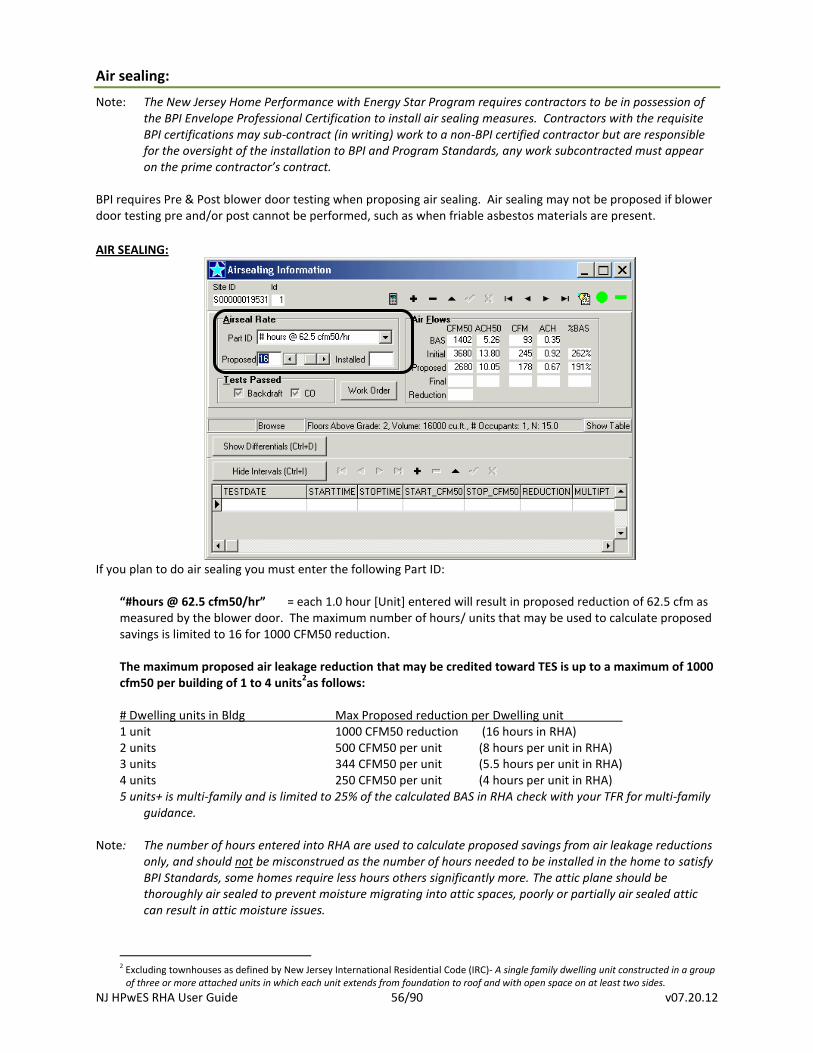
AIR SEALING:
If you plan to do air sealing you must enter the following Part ID:
“#hours @ 62.5 cfm50/hr” = each 1.0 hour [Unit] entered will result in proposed reduction of 62.5 cfm as measured by the blower door. The maximum number of hours/ units that may be used to calculate proposed savings is limited to 16 for 1000 CFM50 reduction. The maximum proposed air leakage reduction that may be credited toward TES is up to a maximum of 1000 cfm50 per building of 1 to 4 units
2as follows:
# Dwelling units in Bldg Max Proposed reduction per Dwelling unit 1 unit 1000 CFM50 reduction (16 hours in RHA) 2 units 500 CFM50 per unit (8 hours per unit in RHA) 3 units 344 CFM50 per unit (5.5 hours per unit in RHA) 4 units 250 CFM50 per unit (4 hours per unit in RHA) 5 units+ is multi-family and is limited to 25% of the calculated BAS in RHA check with your TFR for multi-family
guidance.
Note: The number of hours entered into RHA are used to calculate proposed savings from air leakage reductions only, and should not be misconstrued as the number of hours needed to be installed in the home to satisfy BPI Standards, some homes require less hours others significantly more. The attic plane should be thoroughly air sealed to prevent moisture migrating into attic spaces, poorly or partially air sealed attic can result in attic moisture issues.
2 Excluding townhouses as defined by New Jersey International Residential Code (IRC)- A single family dwelling unit constructed in a group
of three or more attached units in which each unit extends from foundation to roof and with open space on at least two sides.
NJ HPwES RHA User Guide 57/90 v07.20.12
The amount, hours, or effort of air sealing actually proposed, contracted, and ultimately installed in the home is dictated by the BPI Envelope Standard that requires the attic plane to be thoroughly air sealed to provide an effective air barrier and if the dwelling includes an attached garage, air sealing must be performed between the garage and the living space. Attic access must also be addressed as part of the through air sealing.
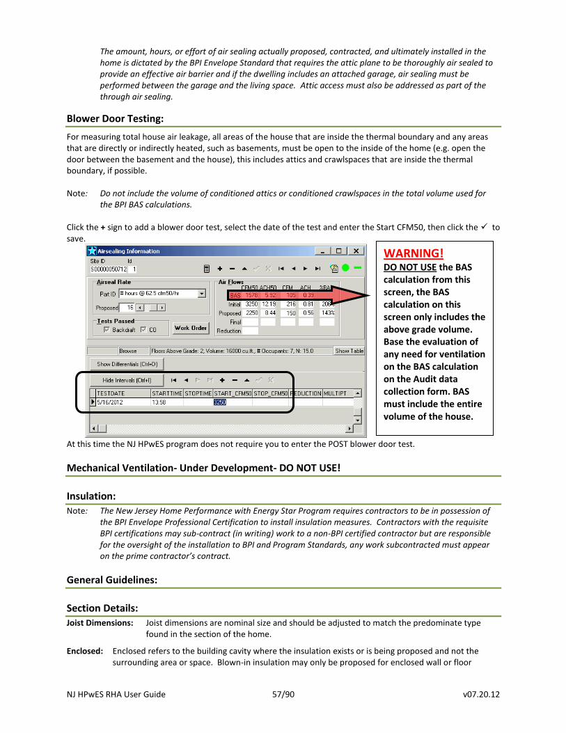
Blower Door Testing:
For measuring total house air leakage, all areas of the house that are inside the thermal boundary and any areas that are directly or indirectly heated, such as basements, must be open to the inside of the home (e.g. open the door between the basement and the house), this includes attics and crawlspaces that are inside the thermal boundary, if possible. Note: Do not include the volume of conditioned attics or conditioned crawlspaces in the total volume used for
the BPI BAS calculations. Click the + sign to add a blower door test, select the date of the test and enter the Start CFM50, then click the to save.
At this time the NJ HPwES program does not require you to enter the POST blower door test.
Mechanical Ventilation- Under Development- DO NOT USE!
Insulation:
Note: The New Jersey Home Performance with Energy Star Program requires contractors to be in possession of the BPI Envelope Professional Certification to install insulation measures. Contractors with the requisite BPI certifications may sub-contract (in writing) work to a non-BPI certified contractor but are responsible for the oversight of the installation to BPI and Program Standards, any work subcontracted must appear on the prime contractor’s contract.
General Guidelines:
Section Details:
Joist Dimensions: Joist dimensions are nominal size and should be adjusted to match the predominate type found in the section of the home.
Enclosed: Enclosed refers to the building cavity where the insulation exists or is being proposed and not the surrounding area or space. Blown-in insulation may only be proposed for enclosed wall or floor
WARNING! DO NOT USE the BAS calculation from this screen, the BAS calculation on this screen only includes the above grade volume. Base the evaluation of any need for ventilation on the BAS calculation on the Audit data collection form. BAS must include the entire volume of the house.
NJ HPwES RHA User Guide 58/90 v07.20.12
cavities, enclosed attic cavities must be dense-packed, and batt insulation materials cannot be proposed for enclosed cavities.
Storage [sq.ft.]: Has no impact on anything – not necessary to fill in.
Rec. Lights: Has no impact on anything – not necessary to fill.
Existing insulation:
The existing insulation modeled in RHA MUST match as indicated on the audit form and should reflect what actually exists in the home.
Type: Use the closet match to what is actually in the home.
Inches: Use the following guidelines to determine the Inches of insulation to enter: Blown/sprayed-in: round the measured typical depth to the closet whole inch. Batts: ≤2-inch batts enter as measured ~R-3 – R7 3 to 4-inch batts enter as 3-inches ~R11 5 to 7-inch batts enter as 6-inches ~R19 8 to 10-inch batts enter as 9-inches ~R30 11+-inch batts enter as 11-inches ~R38
Gaps: The voids between batt insulation and framing should be accounted for, below are the BPI definitions of Gaps and the RHA Voids equivalents :
BPI Gaps RHA Voids o Good – No gaps or other imperfections ............................................. None o Fair – Gaps over 2.5% of the insulated area. ..................................... ~0.25” (This equals3/8 inch space along a 14.5-inch batt.) o Poor – Gaps over 5% of the insulated area. ....................................... ~0.50”+ (This equals¾-inch space along a 14.5-inch batt.)
NOTE: Rarely, is an entire attic insulation area found to meet the “Poor” definition. Insulation is usually found to fit between the framing with only minor voids, which meets the “Good” or in some cases the “Fair” definition. IF there is a large void area (area with R-0 insulation), break out the estimated sq ft of that area and enter as separate entries with “no existing insulation”, then propose an upgrade.
Effective R: The effective R-value is an estimated evaluation of the ability of the existing insulation
including framing, sheathing, drywall, and air films at reducing heat loss, taking into account the grading of Voids. DO NOT Degrade insulation effectiveness using the chart in the BPI Standards and also apply Voids, this will result in understating the effectiveness of the existing insulation and overstate savings.
Proposed Insulation:
The proposed insulation must match what is stated on your contract and this is what MUST be installed, if you propose 10-inches, the 10-inches must be SETTLED DEPTH as 10-inches will be inspected for in the home. Insulation must be installed as per BPI Standards, relevant NJ Code, and manufacturer’s specifications.
Resulting R: The Resulting R-value is not the R-value of the proposed insulation; the resulting r-value
includes any applicable existing insulation with voids improved to “good”, framing, sheathing, drywall and air films and is based on there being no gaps, voids, or compressions after upgraded.
Type: Other [see notes]: Use the Other to model any insulation that is not closely matched by items listed
in the Type menu or to model combinations of insulation installed on one surface, such as high density foam covered with low density foam.
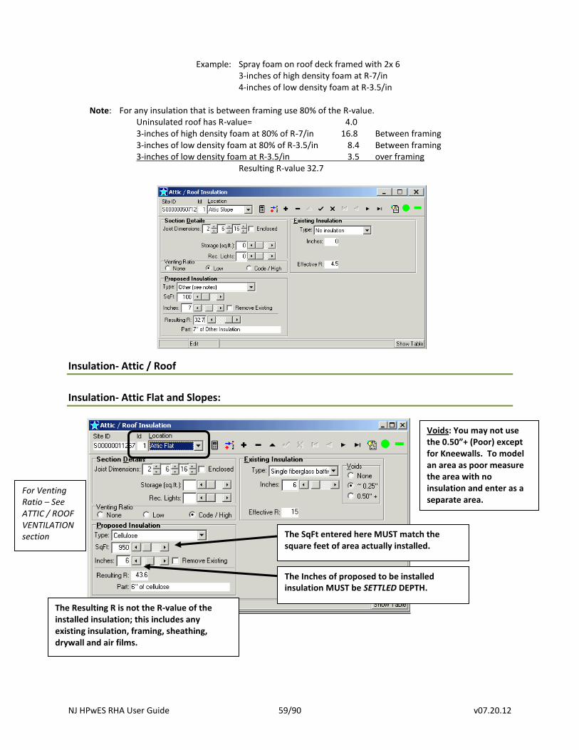
NJ HPwES RHA User Guide 59/90 v07.20.12
Example: Spray foam on roof deck framed with 2x 6
3-inches of high density foam at R-7/in 4-inches of low density foam at R-3.5/in
Note: For any insulation that is between framing use 80% of the R-value.
Uninsulated roof has R-value= 4.0 3-inches of high density foam at 80% of R-7/in 16.8 Between framing
3-inches of low density foam at 80% of R-3.5/in 8.4 Between framing 3-inches of low density foam at R-3.5/in 3.5 over framing
Resulting R-value 32.7
Insulation- Attic / Roof
Insulation- Attic Flat and Slopes:
For Venting Ratio – See ATTIC / ROOF VENTILATION section
Voids: You may not use the 0.50”+ (Poor) except for Kneewalls. To model an area as poor measure the area with no insulation and enter as a separate area.
The SqFt entered here MUST match the square feet of area actually installed.
The Inches of proposed to be installed insulation MUST be SETTLED DEPTH.
The Resulting R is not the R-value of the installed insulation; this includes any existing insulation, framing, sheathing, drywall and air films.
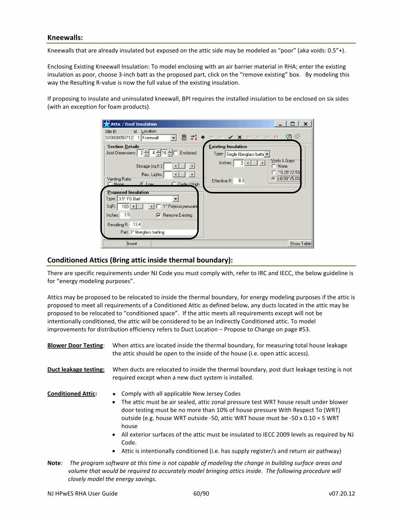
NJ HPwES RHA User Guide 60/90 v07.20.12
Kneewalls:
Kneewalls that are already insulated but exposed on the attic side may be modeled as “poor” (aka voids: 0.5”+). Enclosing Existing Kneewall Insulation: To model enclosing with an air barrier material in RHA; enter the existing insulation as poor, choose 3-inch batt as the proposed part, click on the “remove existing” box. By modeling this way the Resulting R-value is now the full value of the existing insulation. If proposing to insulate and uninsulated kneewall, BPI requires the installed insulation to be enclosed on six sides (with an exception for foam products).
Conditioned Attics (Bring attic inside thermal boundary):
There are specific requirements under NJ Code you must comply with, refer to IRC and IECC, the below guideline is for “energy modeling purposes”. Attics may be proposed to be relocated to inside the thermal boundary, for energy modeling purposes if the attic is proposed to meet all requirements of a Conditioned Attic as defined below, any ducts located in the attic may be proposed to be relocated to “conditioned space”. If the attic meets all requirements except will not be intentionally conditioned, the attic will be considered to be an Indirectly Conditioned attic. To model improvements for distribution efficiency refers to Duct Location – Propose to Change on page #53. Blower Door Testing: When attics are located inside the thermal boundary, for measuring total house leakage
the attic should be open to the inside of the house (i.e. open attic access). Duct leakage testing: When ducts are relocated to inside the thermal boundary, post duct leakage testing is not
required except when a new duct system is installed. Conditioned Attic: ● Comply with all applicable New Jersey Codes
The attic must be air sealed, attic zonal pressure test WRT house result under blower door testing must be no more than 10% of house pressure With Respect To (WRT) outside (e.g. house WRT outside -50, attic WRT house must be -50 x 0.10 = 5 WRT house
All exterior surfaces of the attic must be insulated to IECC 2009 levels as required by NJ Code.
Attic is intentionally conditioned (i.e. has supply register/s and return air pathway)
Note: The program software at this time is not capable of modeling the change in building surface areas and volume that would be required to accurately model bringing attics inside. The following procedure will closely model the energy savings.
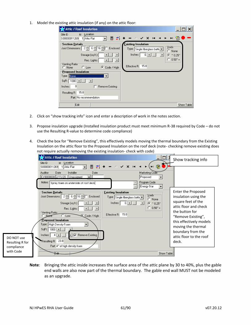
NJ HPwES RHA User Guide 61/90 v07.20.12
1. Model the existing attic insulation (if any) on the attic floor:
2. Click on “show tracking info” icon and enter a description of work in the notes section.
3. Propose insulation upgrade (Installed insulation product must meet minimum R-38 required by Code – do not use the Resulting R-value to determine code compliance)
4. Check the box for “Remove Existing”, this effectively models moving the thermal boundary from the Existing
Insulation on the attic floor to the Proposed Insulation on the roof deck (note- checking remove existing does not require actually removing the existing insulation- check with code)
Note: Bringing the attic inside increases the surface area of the attic plane by 30 to 40%, plus the gable
end walls are also now part of the thermal boundary. The gable end wall MUST not be modeled as an upgrade.
Show tracking info
Enter the Proposed insulation using the square feet of the attic floor and check the button for “Remove Existing”, this effectively models moving the thermal boundary from the attic floor to the roof deck.
DO NOT use Resulting R for compliance with Code
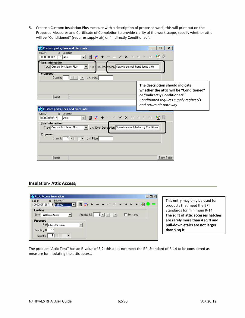
NJ HPwES RHA User Guide 62/90 v07.20.12
5. Create a Custom: Insulation Plus measure with a description of proposed work, this will print out on the
Proposed Measures and Certificate of Completion to provide clarity of the work scope, specify whether attic will be “Conditioned” (requires supply air) or “Indirectly Conditioned”.
Insulation- Attic Access:
The product “Attic Tent” has an R-value of 3.2; this does not meet the BPI Standard of R-14 to be considered as measure for insulating the attic access.
This entry may only be used for products that meet the BPI Standards for minimum R-14 The sq ft of attic accesses hatches are rarely more than 4 sq ft and pull-down-stairs are not larger than 9 sq ft.
The description should indicate whether the attic will be “Conditioned” or “Indirectly Conditioned”. Conditioned requires supply register/s and return air pathway.
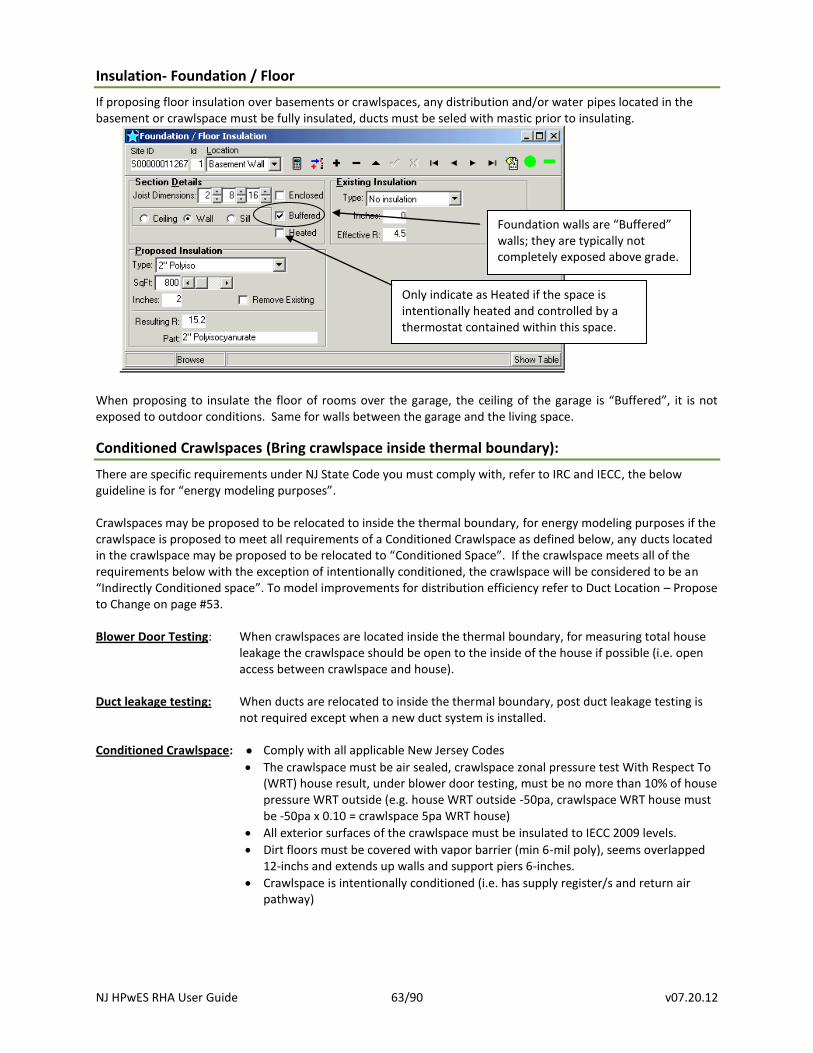
NJ HPwES RHA User Guide 63/90 v07.20.12
Insulation- Foundation / Floor
If proposing floor insulation over basements or crawlspaces, any distribution and/or water pipes located in the basement or crawlspace must be fully insulated, ducts must be seled with mastic prior to insulating.
When proposing to insulate the floor of rooms over the garage, the ceiling of the garage is “Buffered”, it is not exposed to outdoor conditions. Same for walls between the garage and the living space.
Conditioned Crawlspaces (Bring crawlspace inside thermal boundary):
There are specific requirements under NJ State Code you must comply with, refer to IRC and IECC, the below guideline is for “energy modeling purposes”. Crawlspaces may be proposed to be relocated to inside the thermal boundary, for energy modeling purposes if the crawlspace is proposed to meet all requirements of a Conditioned Crawlspace as defined below, any ducts located in the crawlspace may be proposed to be relocated to “Conditioned Space”. If the crawlspace meets all of the requirements below with the exception of intentionally conditioned, the crawlspace will be considered to be an “Indirectly Conditioned space”. To model improvements for distribution efficiency refer to Duct Location – Propose to Change on page #53. Blower Door Testing: When crawlspaces are located inside the thermal boundary, for measuring total house
leakage the crawlspace should be open to the inside of the house if possible (i.e. open access between crawlspace and house).
Duct leakage testing: When ducts are relocated to inside the thermal boundary, post duct leakage testing is
not required except when a new duct system is installed. Conditioned Crawlspace: ● Comply with all applicable New Jersey Codes
The crawlspace must be air sealed, crawlspace zonal pressure test With Respect To (WRT) house result, under blower door testing, must be no more than 10% of house pressure WRT outside (e.g. house WRT outside -50pa, crawlspace WRT house must be -50pa x 0.10 = crawlspace 5pa WRT house)
All exterior surfaces of the crawlspace must be insulated to IECC 2009 levels.
Dirt floors must be covered with vapor barrier (min 6-mil poly), seems overlapped 12-inchs and extends up walls and support piers 6-inches.
Crawlspace is intentionally conditioned (i.e. has supply register/s and return air pathway)
Foundation walls are “Buffered” walls; they are typically not completely exposed above grade.
Only indicate as Heated if the space is intentionally heated and controlled by a thermostat contained within this space.
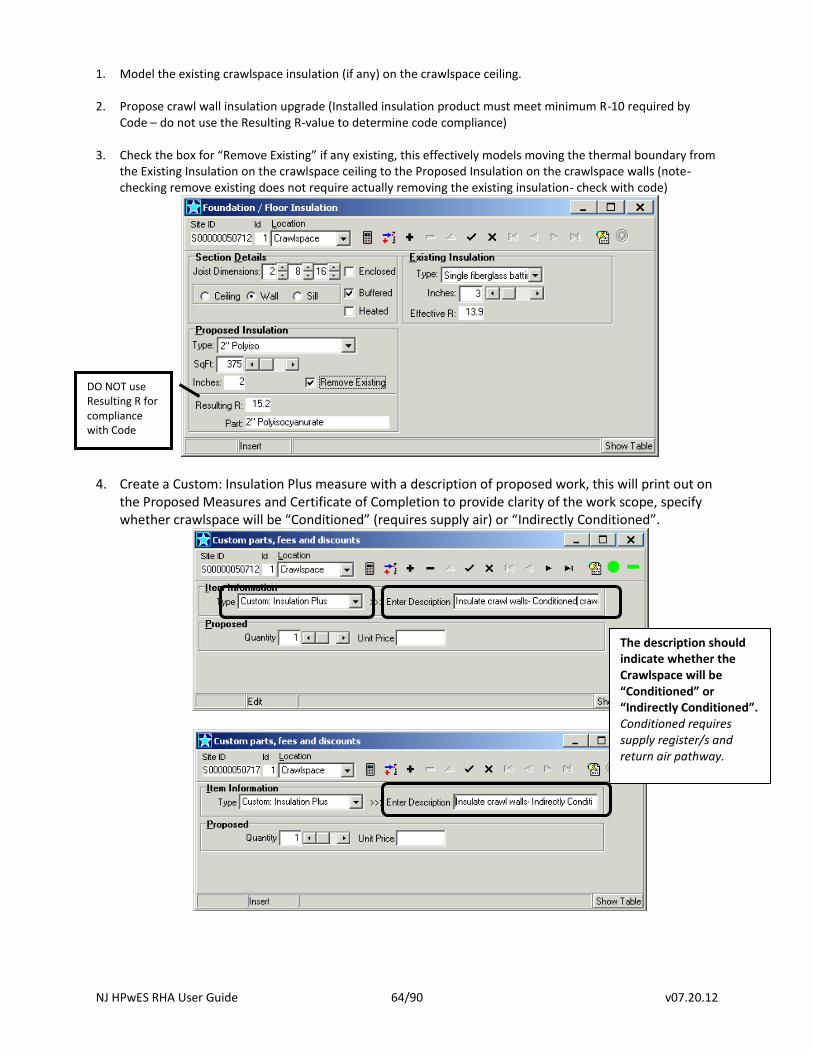
NJ HPwES RHA User Guide 64/90 v07.20.12
1. Model the existing crawlspace insulation (if any) on the crawlspace ceiling.
2. Propose crawl wall insulation upgrade (Installed insulation product must meet minimum R-10 required by Code – do not use the Resulting R-value to determine code compliance)
3. Check the box for “Remove Existing” if any existing, this effectively models moving the thermal boundary from
the Existing Insulation on the crawlspace ceiling to the Proposed Insulation on the crawlspace walls (note- checking remove existing does not require actually removing the existing insulation- check with code)
4. Create a Custom: Insulation Plus measure with a description of proposed work, this will print out on the Proposed Measures and Certificate of Completion to provide clarity of the work scope, specify whether crawlspace will be “Conditioned” (requires supply air) or “Indirectly Conditioned”.
DO NOT use Resulting R for compliance with Code
The description should indicate whether the Crawlspace will be “Conditioned” or “Indirectly Conditioned”. Conditioned requires supply register/s and return air pathway.
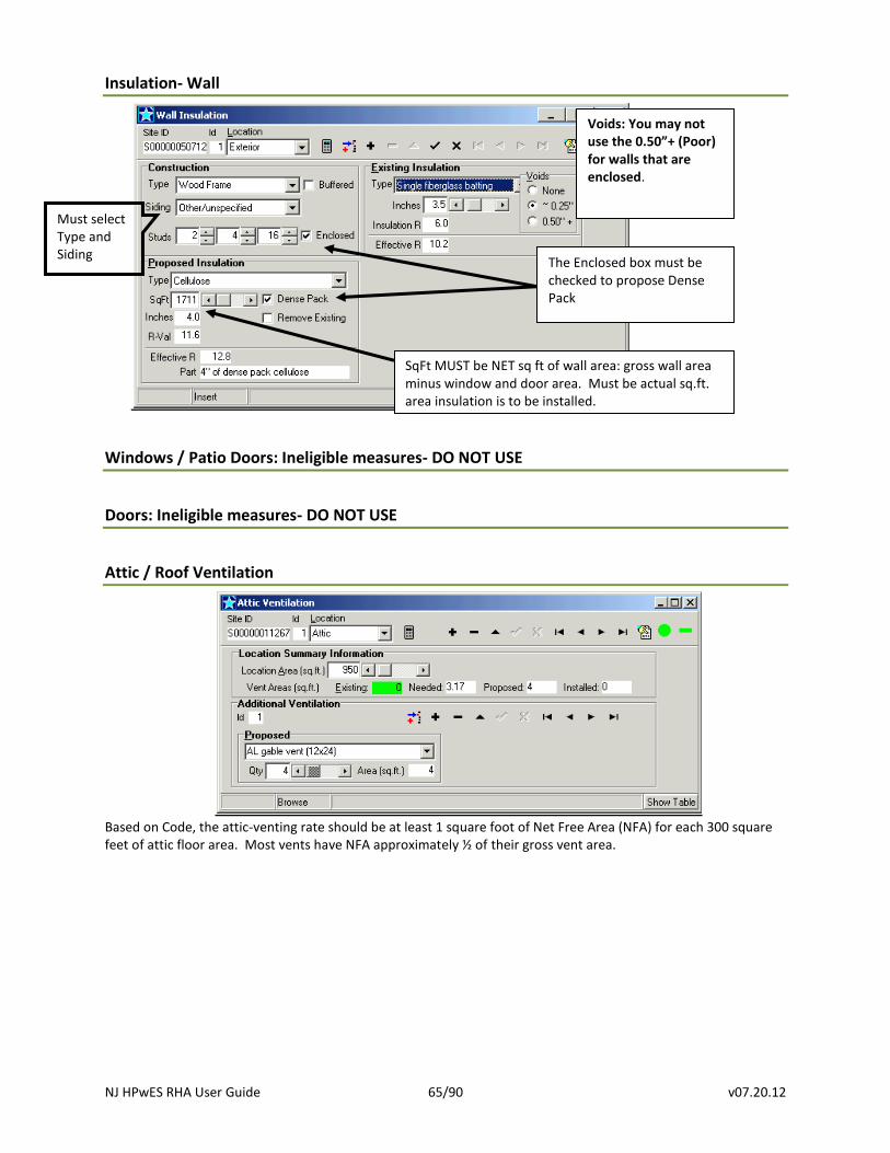
NJ HPwES RHA User Guide 65/90 v07.20.12
Insulation- Wall
Windows / Patio Doors: Ineligible measures- DO NOT USE
Doors: Ineligible measures- DO NOT USE
Attic / Roof Ventilation
Based on Code, the attic-venting rate should be at least 1 square foot of Net Free Area (NFA) for each 300 square feet of attic floor area. Most vents have NFA approximately ½ of their gross vent area.
The Enclosed box must be checked to propose Dense Pack
Voids: You may not use the 0.50”+ (Poor) for walls that are enclosed.
SqFt MUST be NET sq ft of wall area: gross wall area minus window and door area. Must be actual sq.ft. area insulation is to be installed.
Must select Type and Siding
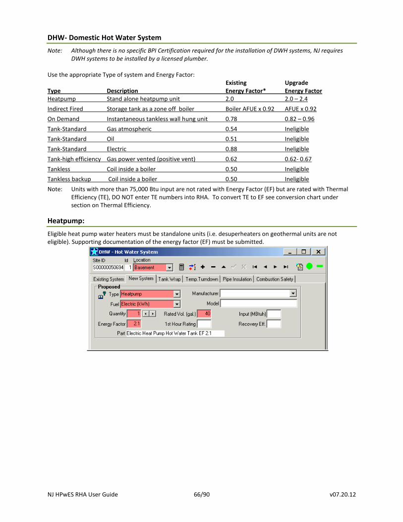
NJ HPwES RHA User Guide 66/90 v07.20.12
DHW- Domestic Hot Water System
Note: Although there is no specific BPI Certification required for the installation of DWH systems, NJ requires DWH systems to be installed by a licensed plumber.
Use the appropriate Type of system and Energy Factor: Existing Upgrade Type Description Energy Factor* Energy Factor Heatpump Stand alone heatpump unit 2.0 2.0 – 2.4
Indirect Fired Storage tank as a zone off boiler Boiler AFUE x 0.92 AFUE x 0.92
On Demand Instantaneous tankless wall hung unit 0.78 0.82 – 0.96
Tank-Standard Gas atmospheric 0.54 Ineligible
Tank-Standard Oil 0.51 Ineligible
Tank-Standard Electric 0.88 Ineligible
Tank-high efficiency Gas power vented (positive vent) 0.62 0.62- 0.67
Tankless Coil inside a boiler 0.50 Ineligible
Tankless backup Coil inside a boiler 0.50 Ineligible
Note: Units with more than 75,000 Btu input are not rated with Energy Factor (EF) but are rated with Thermal Efficiency (TE), DO NOT enter TE numbers into RHA. To convert TE to EF see conversion chart under section on Thermal Efficiency.
Heatpump:
Eligible heat pump water heaters must be standalone units (i.e. desuperheaters on geothermal units are not eligible). Supporting documentation of the energy factor (EF) must be submitted.
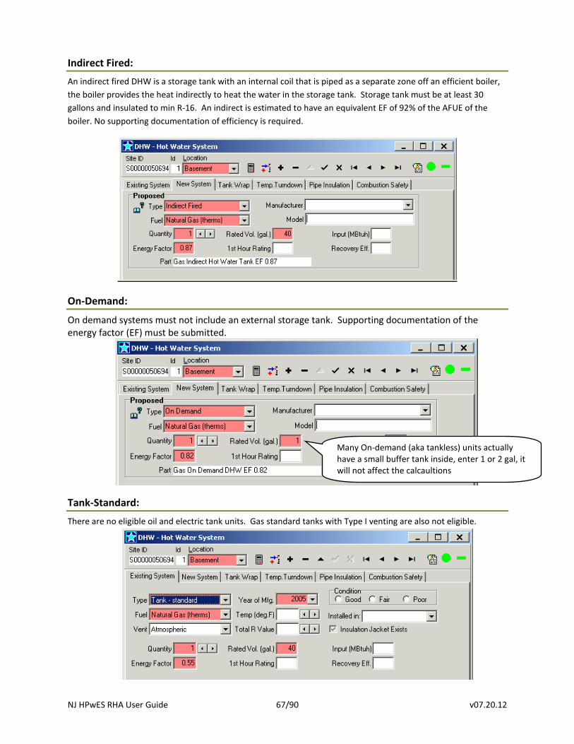
NJ HPwES RHA User Guide 67/90 v07.20.12
Indirect Fired:
An indirect fired DHW is a storage tank with an internal coil that is piped as a separate zone off an efficient boiler,
the boiler provides the heat indirectly to heat the water in the storage tank. Storage tank must be at least 30
gallons and insulated to min R-16. An indirect is estimated to have an equivalent EF of 92% of the AFUE of the
boiler. No supporting documentation of efficiency is required.
On-Demand:
On demand systems must not include an external storage tank. Supporting documentation of the energy factor (EF) must be submitted.
Tank-Standard:
There are no eligible oil and electric tank units. Gas standard tanks with Type I venting are also not eligible.
Many On-demand (aka tankless) units actually have a small buffer tank inside, enter 1 or 2 gal, it will not affect the calcaultions
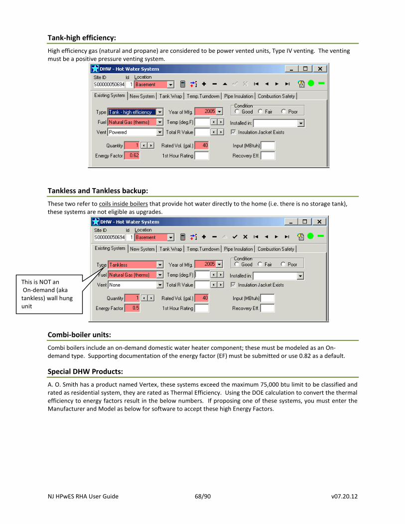
NJ HPwES RHA User Guide 68/90 v07.20.12
Tank-high efficiency:
High efficiency gas (natural and propane) are considered to be power vented units, Type IV venting. The venting must be a positive pressure venting system.
Tankless and Tankless backup:
These two refer to coils inside boilers that provide hot water directly to the home (i.e. there is no storage tank), these systems are not eligible as upgrades.
Combi-boiler units:
Combi boilers include an on-demand domestic water heater component; these must be modeled as an On-demand type. Supporting documentation of the energy factor (EF) must be submitted or use 0.82 as a default.
Special DHW Products:
A. O. Smith has a product named Vertex, these systems exceed the maximum 75,000 btu limit to be classified and rated as residential system, they are rated as Thermal Efficiency. Using the DOE calculation to convert the thermal efficiency to energy factors result in the below numbers. If proposing one of these systems, you must enter the Manufacturer and Model as below for software to accept these high Energy Factors.
This is NOT an On-demand (aka tankless) wall hung unit
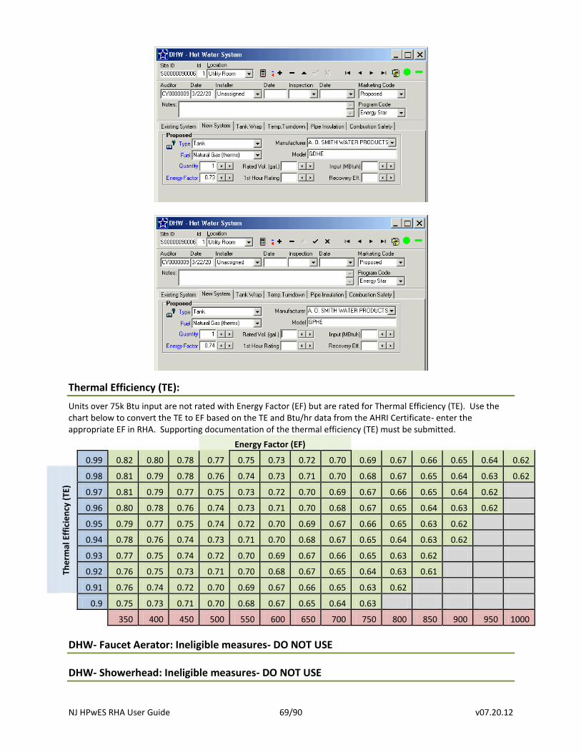
NJ HPwES RHA User Guide 69/90 v07.20.12
Thermal Efficiency (TE):
Units over 75k Btu input are not rated with Energy Factor (EF) but are rated for Thermal Efficiency (TE). Use the chart below to convert the TE to EF based on the TE and Btu/hr data from the AHRI Certificate- enter the appropriate EF in RHA. Supporting documentation of the thermal efficiency (TE) must be submitted.
Energy Factor (EF)
0.99 0.82 0.80 0.78 0.77 0.75 0.73 0.72 0.70 0.69 0.67 0.66 0.65 0.64 0.62
The
rmal
Eff
icie
ncy
(TE
)
0.98 0.81 0.79 0.78 0.76 0.74 0.73 0.71 0.70 0.68 0.67 0.65 0.64 0.63 0.62
0.97 0.81 0.79 0.77 0.75 0.73 0.72 0.70 0.69 0.67 0.66 0.65 0.64 0.62
0.96 0.80 0.78 0.76 0.74 0.73 0.71 0.70 0.68 0.67 0.65 0.64 0.63 0.62
0.95 0.79 0.77 0.75 0.74 0.72 0.70 0.69 0.67 0.66 0.65 0.63 0.62
0.94 0.78 0.76 0.74 0.73 0.71 0.70 0.68 0.67 0.65 0.64 0.63 0.62
0.93 0.77 0.75 0.74 0.72 0.70 0.69 0.67 0.66 0.65 0.63 0.62
0.92 0.76 0.75 0.73 0.71 0.70 0.68 0.67 0.65 0.64 0.63 0.61
0.91 0.76 0.74 0.72 0.70 0.69 0.67 0.66 0.65 0.63 0.62
0.9 0.75 0.73 0.71 0.70 0.68 0.67 0.65 0.64 0.63
350 400 450 500 550 600 650 700 750 800 850 900 950 1000
DHW- Faucet Aerator: Ineligible measures- DO NOT USE
DHW- Showerhead: Ineligible measures- DO NOT USE
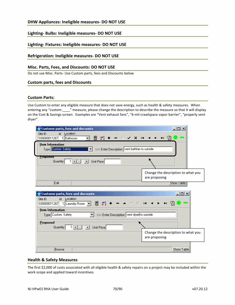
NJ HPwES RHA User Guide 70/90 v07.20.12
DHW Appliances: Ineligible measures- DO NOT USE
Lighting- Bulbs: Ineligible measures- DO NOT USE
Lighting- Fixtures: Ineligible measures- DO NOT USE
Refrigeration: Ineligible measures- DO NOT USE
Misc. Parts, Fees, and Discounts: DO NOT USE
Do not use Misc. Parts- Use Custom parts, fees and Discounts below
Custom parts, fees and Discounts
Custom Parts:
Use Custom to enter any eligible measure that does not save energy, such as health & safety measures. When entering any “custom:____” measure, please change the description to describe the measure so that it will display on the Cost & Savings screen. Examples are “Vent exhaust fans”, “6-mil crawlspace vapor barrier”, “properly vent dryer”.
Health & Safety Measures
The first $2,000 of costs associated with all eligible health & safety repairs on a project may be included within the work scope and applied toward incentives.
Change the description to what you are proposing
Change the description to what you are proposing
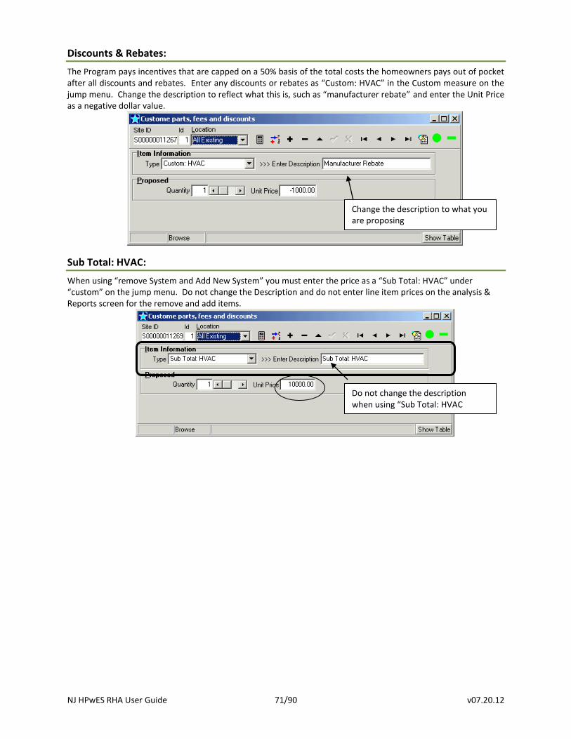
NJ HPwES RHA User Guide 71/90 v07.20.12
Discounts & Rebates:
The Program pays incentives that are capped on a 50% basis of the total costs the homeowners pays out of pocket after all discounts and rebates. Enter any discounts or rebates as “Custom: HVAC” in the Custom measure on the jump menu. Change the description to reflect what this is, such as “manufacturer rebate” and enter the Unit Price as a negative dollar value.
Sub Total: HVAC:
When using “remove System and Add New System” you must enter the price as a “Sub Total: HVAC” under “custom” on the jump menu. Do not change the Description and do not enter line item prices on the analysis & Reports screen for the remove and add items.
Change the description to what you are proposing
Do not change the description when using “Sub Total: HVAC
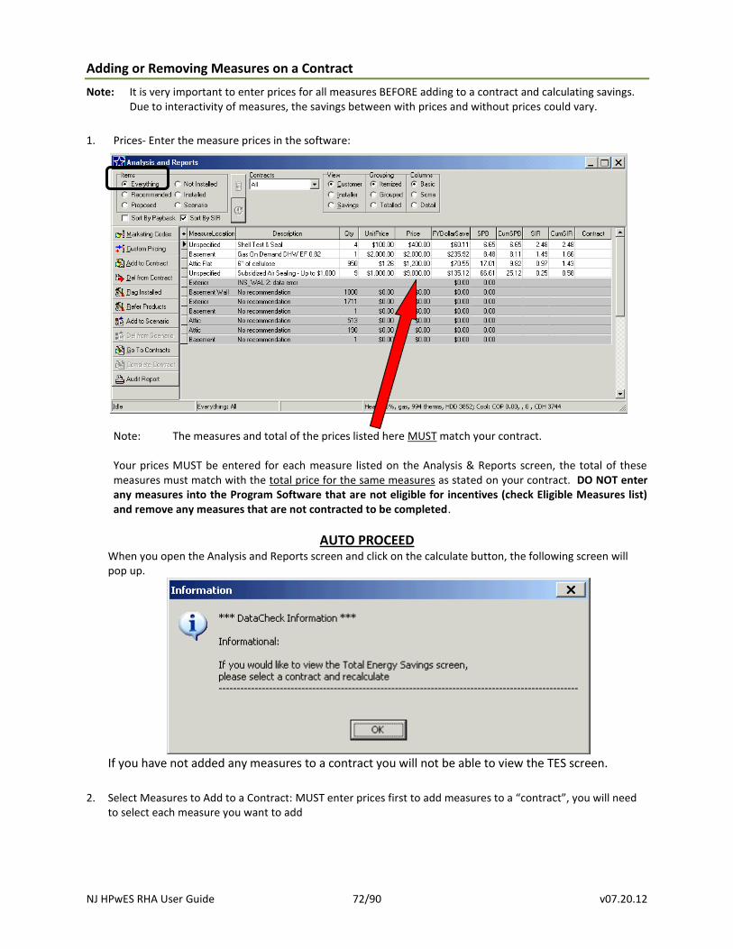
NJ HPwES RHA User Guide 72/90 v07.20.12
Adding or Removing Measures on a Contract
Note: It is very important to enter prices for all measures BEFORE adding to a contract and calculating savings. Due to interactivity of measures, the savings between with prices and without prices could vary.
1. Prices- Enter the measure prices in the software:
Note: The measures and total of the prices listed here MUST match your contract. Your prices MUST be entered for each measure listed on the Analysis & Reports screen, the total of these measures must match with the total price for the same measures as stated on your contract. DO NOT enter any measures into the Program Software that are not eligible for incentives (check Eligible Measures list) and remove any measures that are not contracted to be completed.
AUTO PROCEED When you open the Analysis and Reports screen and click on the calculate button, the following screen will pop up.
If you have not added any measures to a contract you will not be able to view the TES screen.
2. Select Measures to Add to a Contract: MUST enter prices first to add measures to a “contract”, you will need to select each measure you want to add
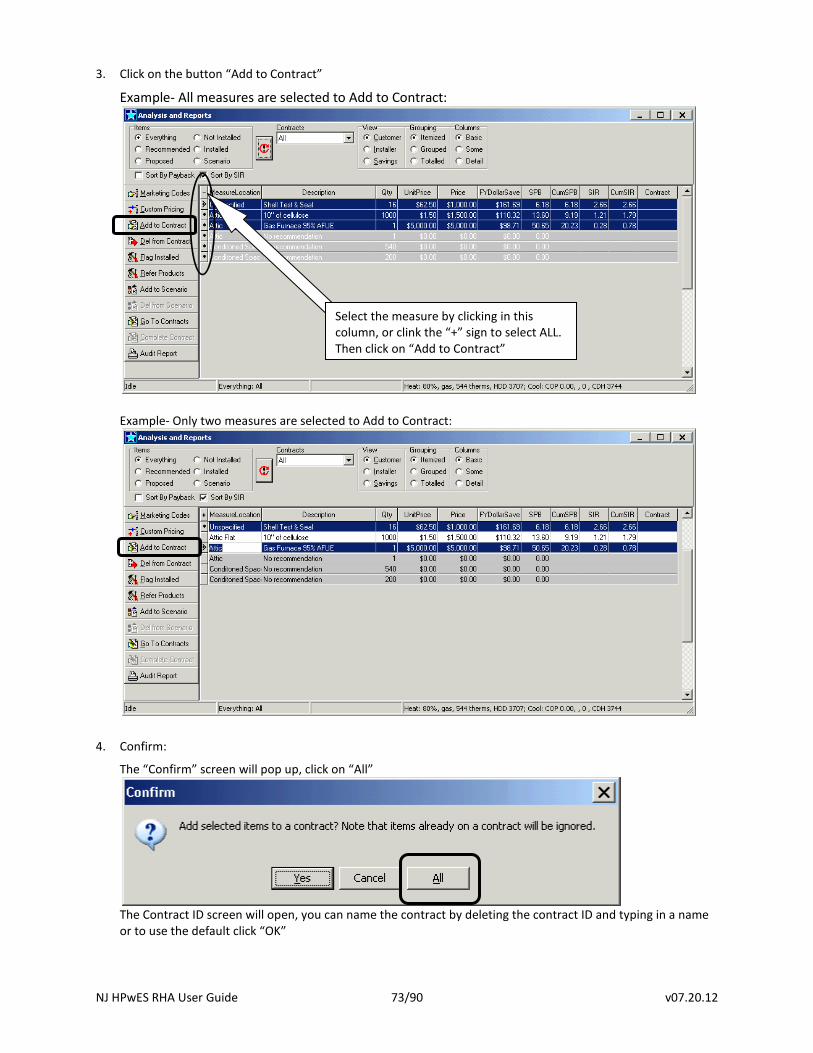
NJ HPwES RHA User Guide 73/90 v07.20.12
3. Click on the button “Add to Contract”
Example- All measures are selected to Add to Contract:
Example- Only two measures are selected to Add to Contract:
4. Confirm:
The “Confirm” screen will pop up, click on “All”
The Contract ID screen will open, you can name the contract by deleting the contract ID and typing in a name or to use the default click “OK”
Select the measure by clicking in this column, or clink the “+” sign to select ALL. Then click on “Add to Contract”
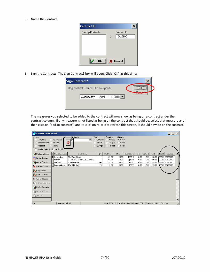
NJ HPwES RHA User Guide 74/90 v07.20.12
5. Name the Contract
6. Sign the Contract: The Sign Contract? box will open; Click “OK” at this time:
The measures you selected to be added to the contract will now show as being on a contract under the contract column. If any measure is not listed as being on the contract that should be, select that measure and then click on “add to contract”, and re-click on re-calc to refresh this screen, it should now be on the contract.
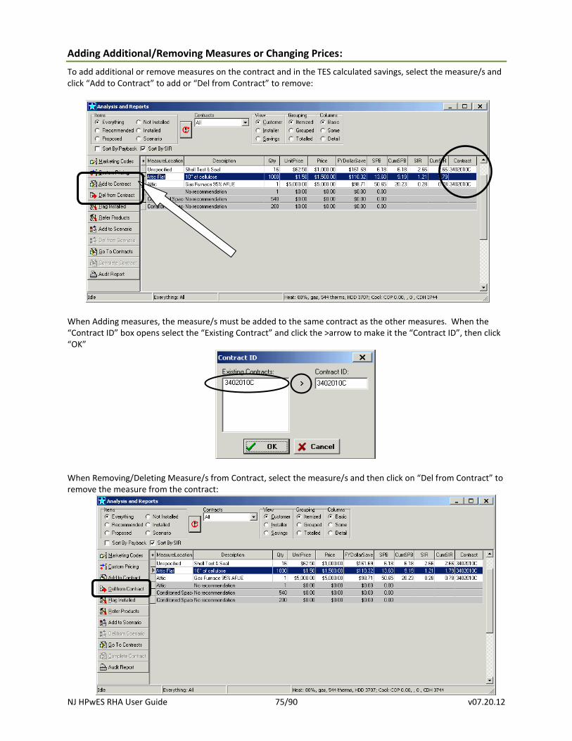
NJ HPwES RHA User Guide 75/90 v07.20.12
Adding Additional/Removing Measures or Changing Prices:
To add additional or remove measures on the contract and in the TES calculated savings, select the measure/s and click “Add to Contract” to add or “Del from Contract” to remove:
When Adding measures, the measure/s must be added to the same contract as the other measures. When the “Contract ID” box opens select the “Existing Contract” and click the >arrow to make it the “Contract ID”, then click “OK”
When Removing/Deleting Measure/s from Contract, select the measure/s and then click on “Del from Contract” to remove the measure from the contract:
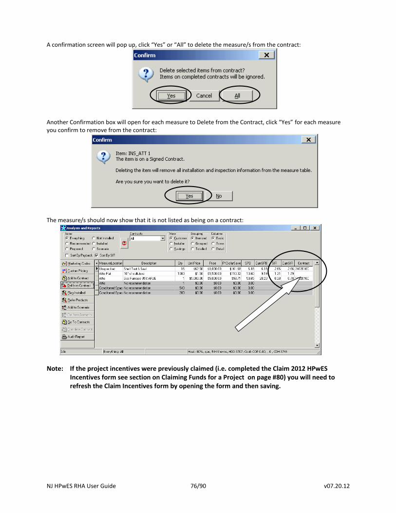
NJ HPwES RHA User Guide 76/90 v07.20.12
A confirmation screen will pop up, click “Yes” or “All” to delete the measure/s from the contract:
Another Confirmation box will open for each measure to Delete from the Contract, click “Yes” for each measure you confirm to remove from the contract:
The measure/s should now show that it is not listed as being on a contract:
Note: If the project incentives were previously claimed (i.e. completed the Claim 2012 HPwES Incentives form see section on Claiming Funds for a Project on page #80) you will need to refresh the Claim Incentives form by opening the form and then saving.
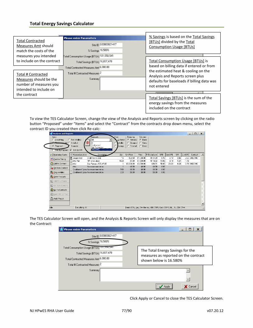
NJ HPwES RHA User Guide 77/90 v07.20.12
Total Energy Savings Calculator
To view the TES Calculator Screen, change the view of the Analysis and Reports screen by clicking on the radio button “Proposed” under “Items” and select the “Contract” from the contracts drop down menu, select the contract ID you created then click Re-calc:
The TES Calculator Screen will open, and the Analysis & Reports Screen will only display the measures that are on the Contract:
Click Apply or Cancel to close the TES Calculator Screen.
The Total Energy Savings for the measures as reported on the contract shown below is 16.580%
Total Consumption Usage [BTUs] is based on billing data if entered or from the estimated heat & cooling on the Analysis and Reports screen plus defaults for baseloads if billing data was not entered
Total # Contracted Measures should be the number of measures you intended to include on the contract
Total Contracted Measures Amt should match the costs of the measures you intended to include on the contract
Total Savings [BTUs] is the sum of the energy savings from the measures included on the contract
% Savings is based on the Total Savings [BTUs] divided by the Total Consumption Usage [BTUs]
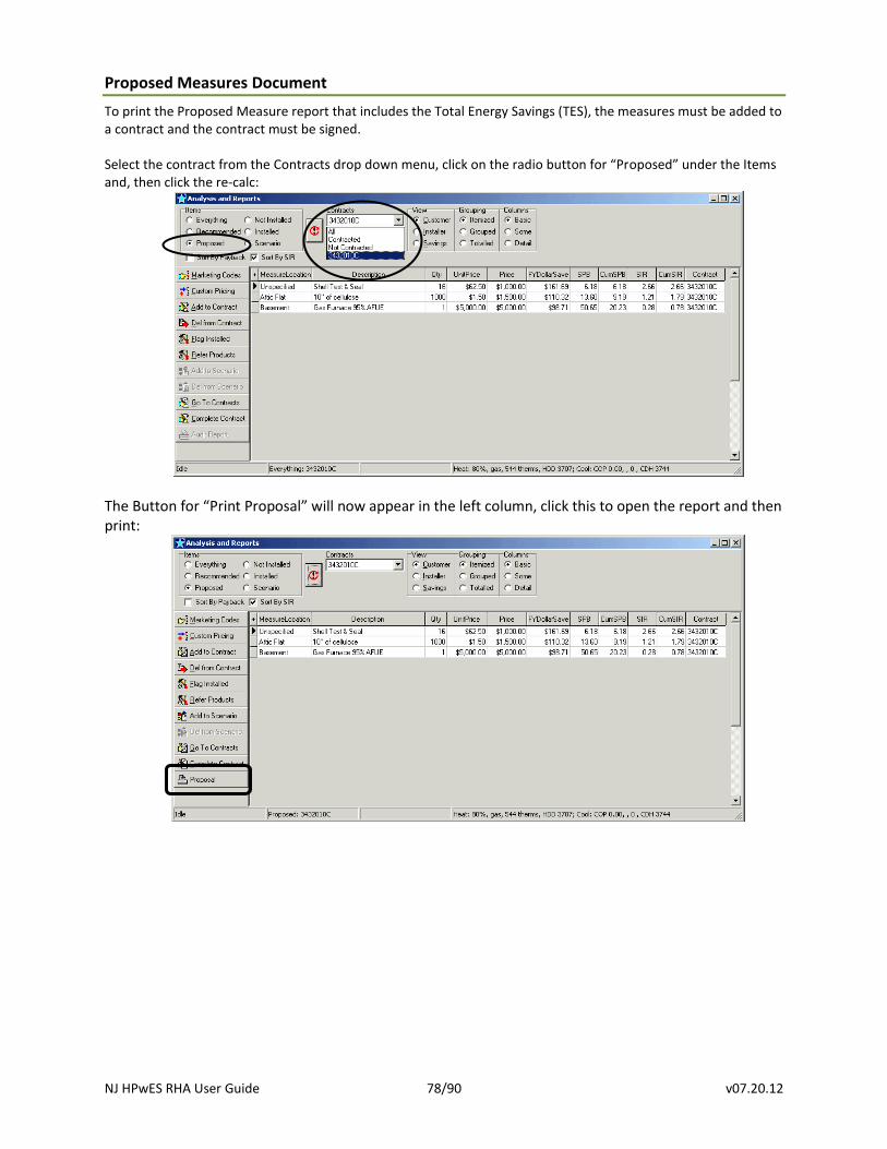
NJ HPwES RHA User Guide 78/90 v07.20.12
Proposed Measures Document
To print the Proposed Measure report that includes the Total Energy Savings (TES), the measures must be added to a contract and the contract must be signed. Select the contract from the Contracts drop down menu, click on the radio button for “Proposed” under the Items and, then click the re-calc:
The Button for “Print Proposal” will now appear in the left column, click this to open the report and then print:
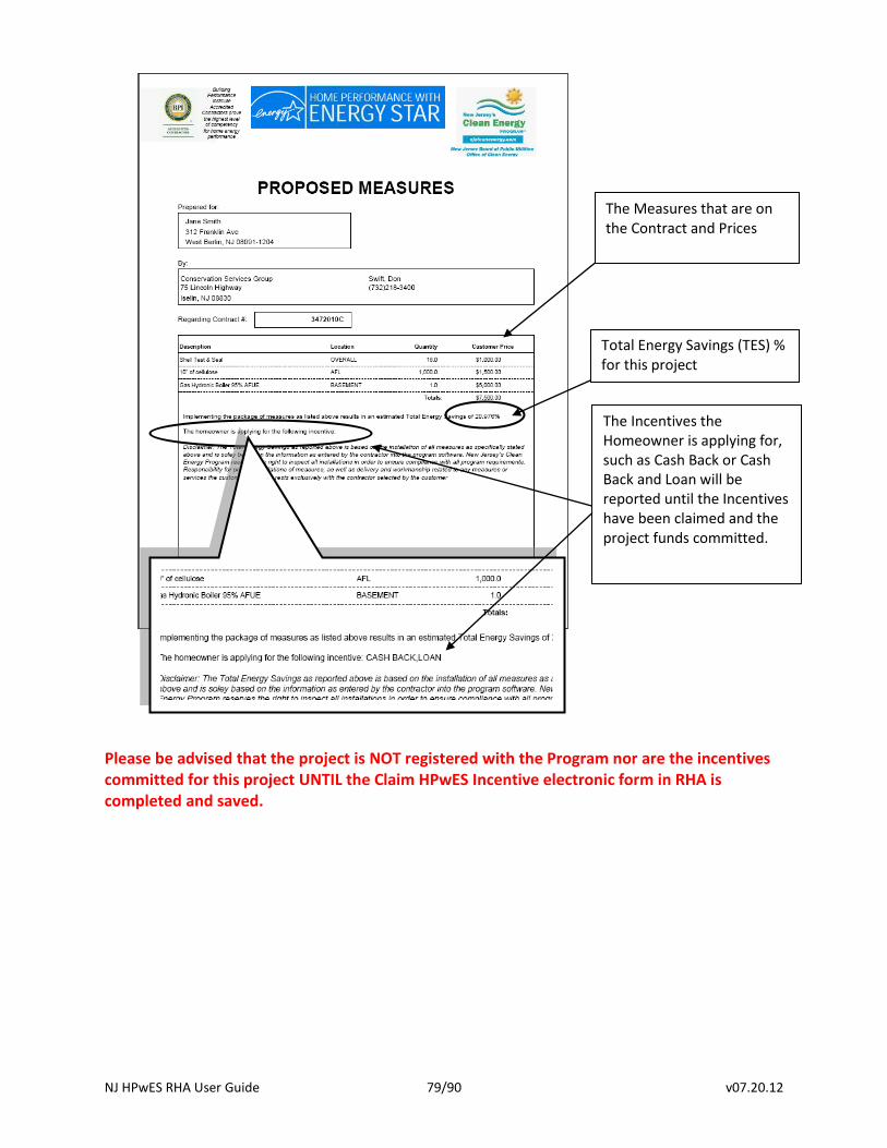
NJ HPwES RHA User Guide 79/90 v07.20.12
Please be advised that the project is NOT registered with the Program nor are the incentives committed for this project UNTIL the Claim HPwES Incentive electronic form in RHA is completed and saved.
Total Energy Savings (TES) % for this project
The Measures that are on the Contract and Prices
The Incentives the Homeowner is applying for, such as Cash Back or Cash Back and Loan will be reported until the Incentives have been claimed and the project funds committed.
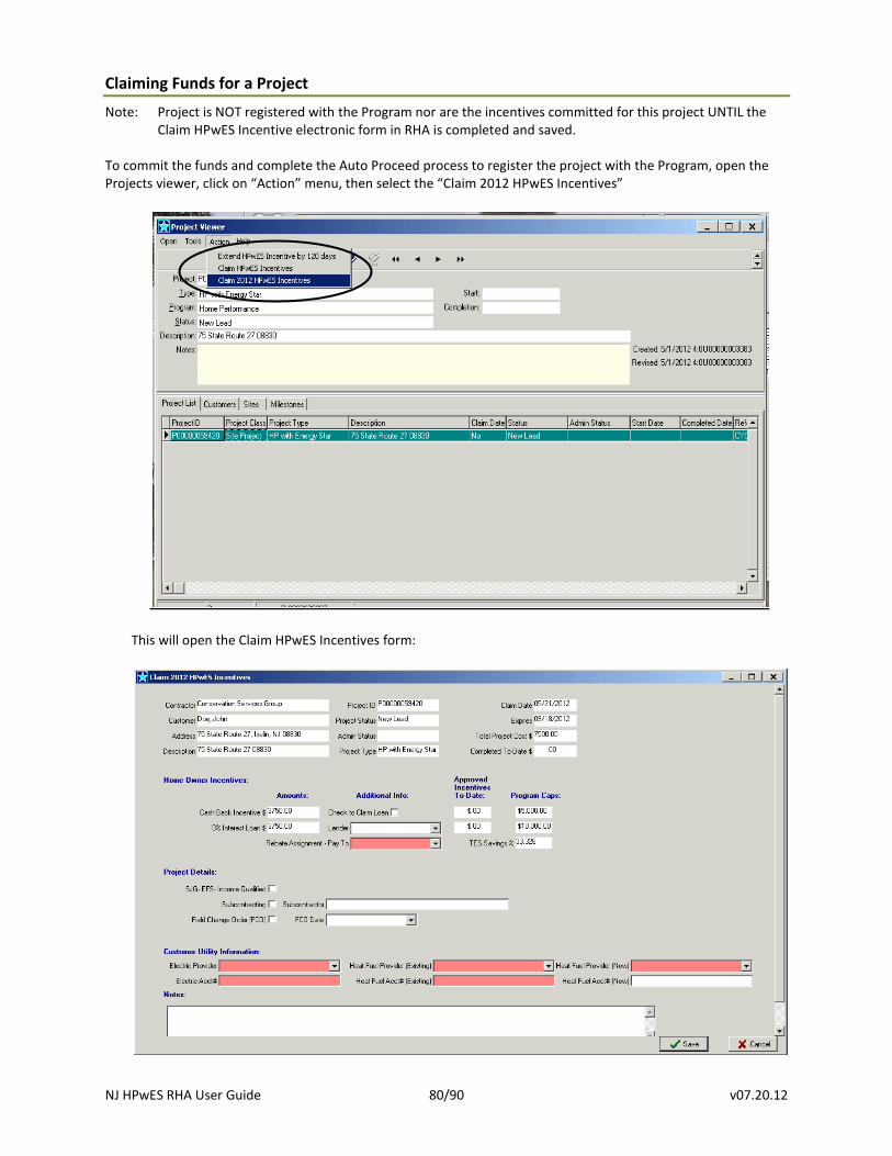
NJ HPwES RHA User Guide 80/90 v07.20.12
Claiming Funds for a Project
Note: Project is NOT registered with the Program nor are the incentives committed for this project UNTIL the Claim HPwES Incentive electronic form in RHA is completed and saved.
To commit the funds and complete the Auto Proceed process to register the project with the Program, open the Projects viewer, click on “Action” menu, then select the “Claim 2012 HPwES Incentives”
This will open the Claim HPwES Incentives form:
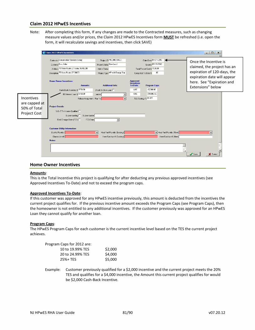
NJ HPwES RHA User Guide 81/90 v07.20.12
Claim 2012 HPwES Incentives
Note: After completing this form, If any changes are made to the Contracted measures, such as changing measure values and/or prices, the Claim 2012 HPwES Incentives form MUST be refreshed (i.e. open the form, it will recalculate savings and incentives, then click SAVE)
Home Owner Incentives
Amounts: This is the Total Incentive this project is qualifying for after deducting any previous approved incentives (see Approved Incentives To-Date) and not to exceed the program caps. Approved Incentives To-Date: If this customer was approved for any HPwES incentive previously, this amount is deducted from the incentives the current project qualifies for. If the previous incentive amount exceeds the Program Caps (see Program Caps), then the homeowner is not entitled to any additional incentives. If the customer previously was approved for an HPwES Loan they cannot qualify for another loan. Program Caps: The HPwES Program Caps for each customer is the current incentive level based on the TES the current project achieves.
Program Caps for 2012 are: 10 to 19.99% TES $2,000 20 to 24.99% TES $4,000 25%+ TES $5,000
Example: Customer previously qualified for a $2,000 incentive and the current project meets the 20% TES and qualifies for a $4,000 incentive, the Amount this current project qualifies for would be $2,000 Cash-Back Incentive.
Once the Incentive is claimed, the project has an expiration of 120-days, the expiration date will appear here. See “Expiration and Extensions” below
Incentives are capped at 50% of Total Project Cost
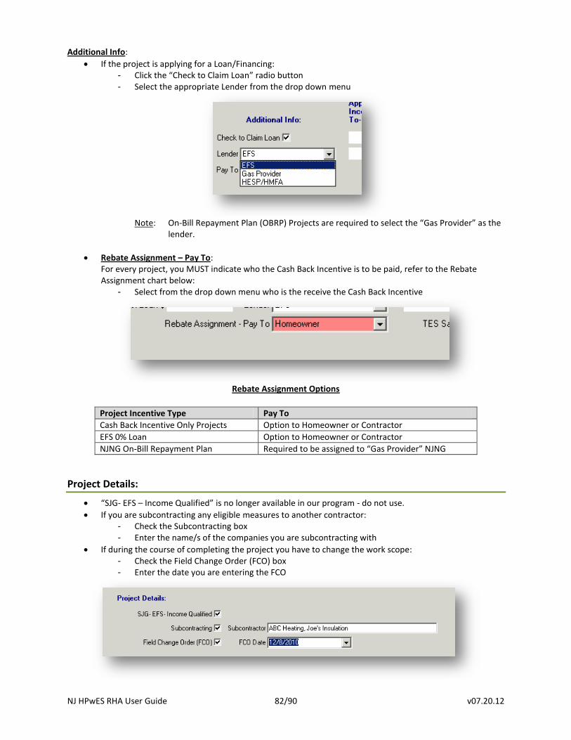
NJ HPwES RHA User Guide 82/90 v07.20.12
Additional Info:
If the project is applying for a Loan/Financing: - Click the “Check to Claim Loan” radio button - Select the appropriate Lender from the drop down menu
Note: On-Bill Repayment Plan (OBRP) Projects are required to select the “Gas Provider” as the
lender.
Rebate Assignment – Pay To: For every project, you MUST indicate who the Cash Back Incentive is to be paid, refer to the Rebate Assignment chart below:
- Select from the drop down menu who is the receive the Cash Back Incentive
Rebate Assignment Options
Project Incentive Type Pay To
Cash Back Incentive Only Projects Option to Homeowner or Contractor
EFS 0% Loan Option to Homeowner or Contractor
NJNG On-Bill Repayment Plan Required to be assigned to “Gas Provider” NJNG
Project Details:
“SJG- EFS – Income Qualified” is no longer available in our program - do not use.
If you are subcontracting any eligible measures to another contractor: - Check the Subcontracting box - Enter the name/s of the companies you are subcontracting with
If during the course of completing the project you have to change the work scope: - Check the Field Change Order (FCO) box - Enter the date you are entering the FCO
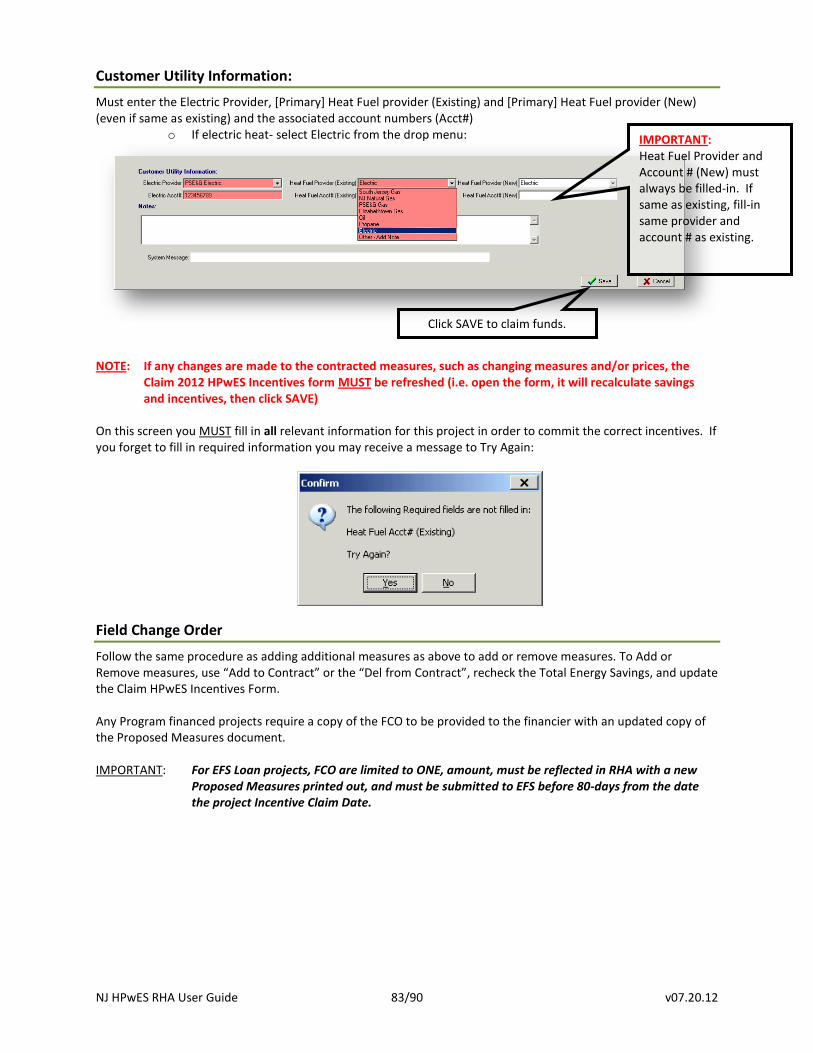
NJ HPwES RHA User Guide 83/90 v07.20.12
Customer Utility Information:
Must enter the Electric Provider, [Primary] Heat Fuel provider (Existing) and [Primary] Heat Fuel provider (New) (even if same as existing) and the associated account numbers (Acct#)
o If electric heat- select Electric from the drop menu:
NOTE: If any changes are made to the contracted measures, such as changing measures and/or prices, the Claim 2012 HPwES Incentives form MUST be refreshed (i.e. open the form, it will recalculate savings and incentives, then click SAVE)
On this screen you MUST fill in all relevant information for this project in order to commit the correct incentives. If you forget to fill in required information you may receive a message to Try Again:
Field Change Order
Follow the same procedure as adding additional measures as above to add or remove measures. To Add or Remove measures, use “Add to Contract” or the “Del from Contract”, recheck the Total Energy Savings, and update the Claim HPwES Incentives Form. Any Program financed projects require a copy of the FCO to be provided to the financier with an updated copy of the Proposed Measures document. IMPORTANT: For EFS Loan projects, FCO are limited to ONE, amount, must be reflected in RHA with a new
Proposed Measures printed out, and must be submitted to EFS before 80-days from the date the project Incentive Claim Date.
Click SAVE to claim funds.
IMPORTANT: Heat Fuel Provider and Account # (New) must always be filled-in. If same as existing, fill-in same provider and account # as existing.
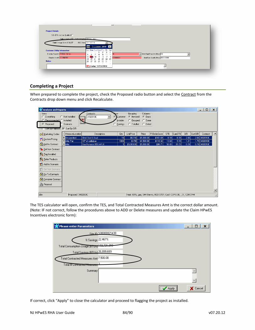
NJ HPwES RHA User Guide 84/90 v07.20.12
Completing a Project
When prepared to complete the project, check the Proposed radio button and select the Contract from the Contracts drop down menu and click Recalculate.
The TES calculator will open, confirm the TES, and Total Contracted Measures Amt is the correct dollar amount. (Note: IF not correct, follow the procedures above to ADD or Delete measures and update the Claim HPwES Incentives electronic form):
If correct, click “Apply” to close the calculator and proceed to flagging the project as installed.
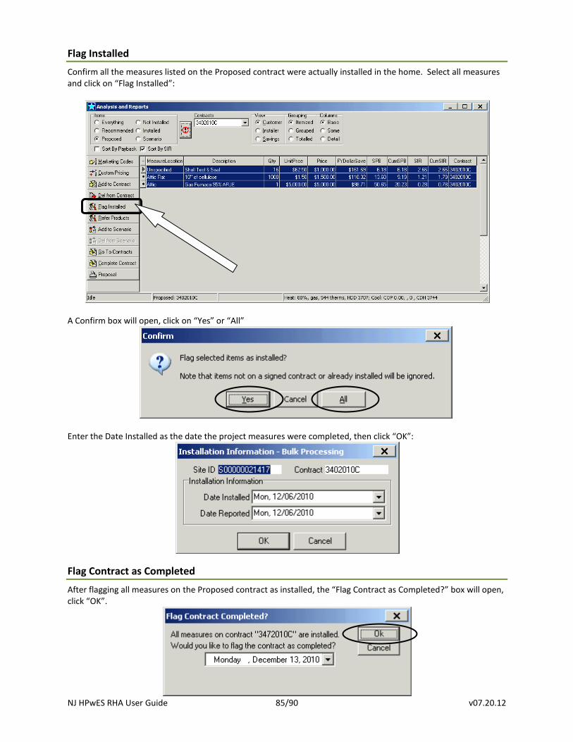
NJ HPwES RHA User Guide 85/90 v07.20.12
Flag Installed
Confirm all the measures listed on the Proposed contract were actually installed in the home. Select all measures and click on “Flag Installed”:
A Confirm box will open, click on “Yes” or “All”
Enter the Date Installed as the date the project measures were completed, then click “OK”:
Flag Contract as Completed
After flagging all measures on the Proposed contract as installed, the “Flag Contract as Completed?” box will open, click “OK”.
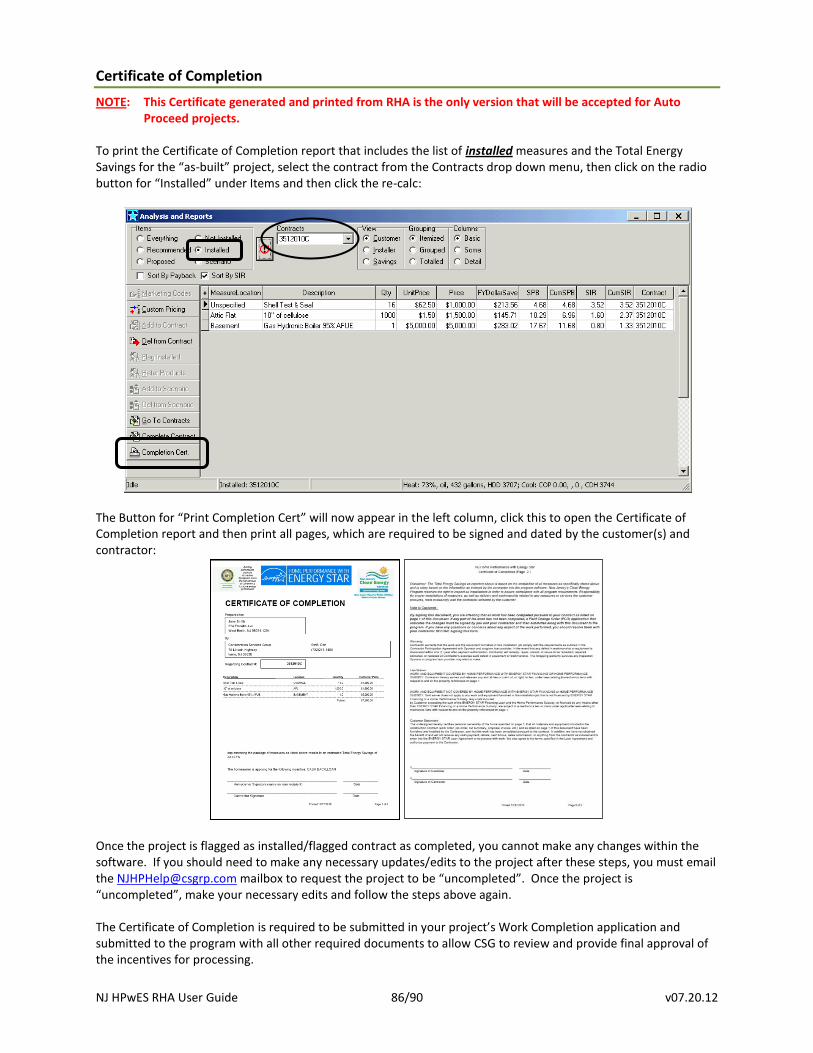
NJ HPwES RHA User Guide 86/90 v07.20.12
Certificate of Completion
NOTE: This Certificate generated and printed from RHA is the only version that will be accepted for Auto Proceed projects.
To print the Certificate of Completion report that includes the list of installed measures and the Total Energy Savings for the “as-built” project, select the contract from the Contracts drop down menu, then click on the radio button for “Installed” under Items and then click the re-calc:
The Button for “Print Completion Cert” will now appear in the left column, click this to open the Certificate of Completion report and then print all pages, which are required to be signed and dated by the customer(s) and contractor:
Once the project is flagged as installed/flagged contract as completed, you cannot make any changes within the software. If you should need to make any necessary updates/edits to the project after these steps, you must email the [email protected] mailbox to request the project to be “uncompleted”. Once the project is “uncompleted”, make your necessary edits and follow the steps above again. The Certificate of Completion is required to be submitted in your project’s Work Completion application and submitted to the program with all other required documents to allow CSG to review and provide final approval of the incentives for processing.
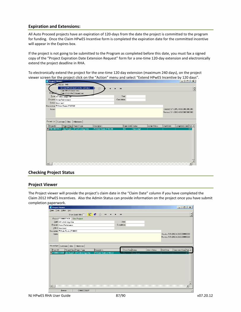
NJ HPwES RHA User Guide 87/90 v07.20.12
Expiration and Extensions:
All Auto Proceed projects have an expiration of 120-days from the date the project is committed to the program for funding. Once the Claim HPwES Incentive form is completed the expiration date for the committed incentive will appear in the Expires box. If the project is not going to be submitted to the Program as completed before this date, you must fax a signed copy of the “Project Expiration Date Extension Request” form for a one-time 120-day extension and electronically extend the project deadline in RHA. To electronically extend the project for the one-time 120 day extension (maximum 240 days), on the project viewer screen for the project click on the “Action” menu and select “Extend HPwES Incentive by 120 days”.
Checking Project Status
Project Viewer
The Project viewer will provide the project’s claim date in the “Claim Date” column if you have completed the Claim 2012 HPwES Incentives. Also the Admin Status can provide information on the project once you have submit completion paperwork.
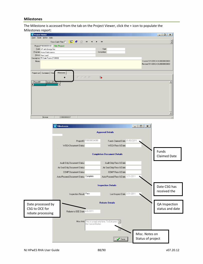
NJ HPwES RHA User Guide 88/90 v07.20.12
Milestones
The Milestone is accessed from the tab on the Project Viewer, click the + icon to populate the Milestones report:
Funds Claimed Date
Date CSG has received the paperwork
QA Inspection status and date paperwork
Date processed by CSG to OCE for rebate processing
Misc. Notes on Status of project
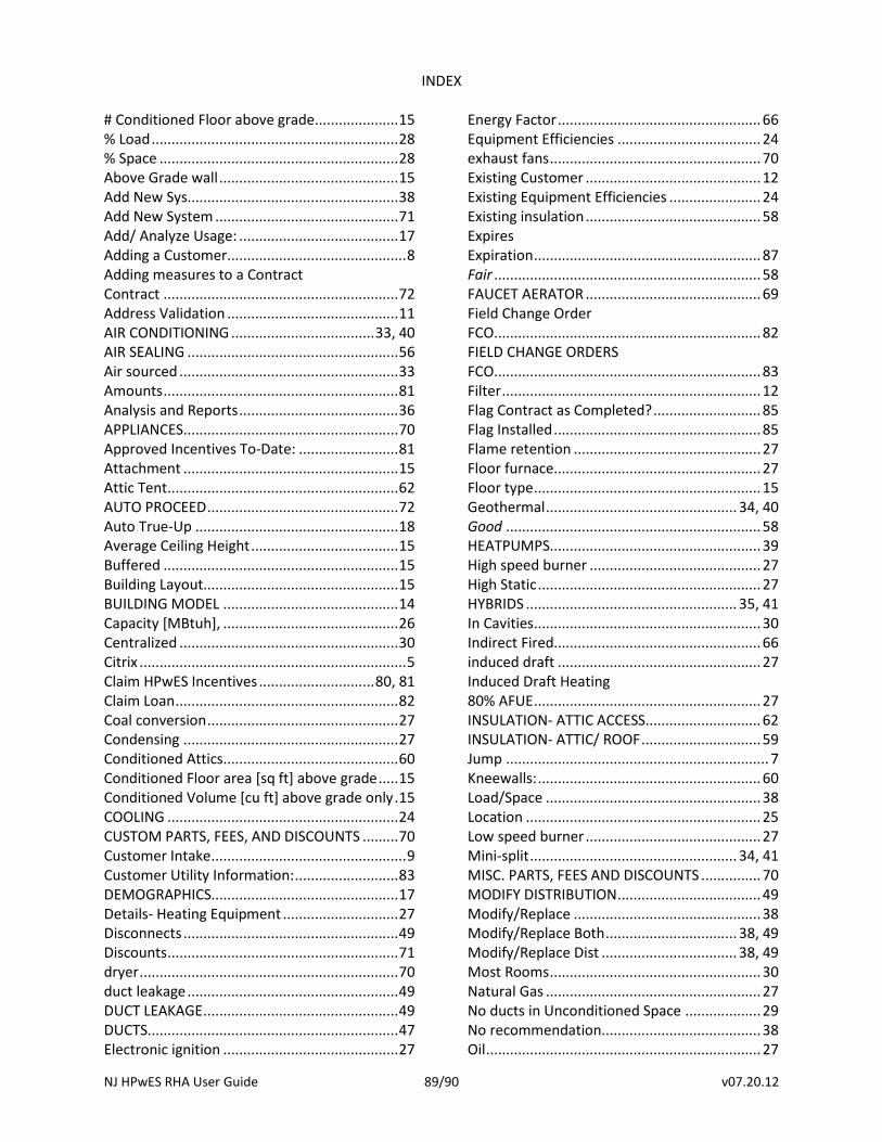
NJ HPwES RHA User Guide 89/90 v07.20.12
INDEX
# Conditioned Floor above grade..................... 15 % Load .............................................................. 28 % Space ............................................................ 28 Above Grade wall ............................................. 15 Add New Sys..................................................... 38 Add New System .............................................. 71 Add/ Analyze Usage: ........................................ 17 Adding a Customer ............................................. 8 Adding measures to a Contract Contract ........................................................... 72 Address Validation ........................................... 11 AIR CONDITIONING .................................... 33, 40 AIR SEALING ..................................................... 56 Air sourced ....................................................... 33 Amounts ........................................................... 81 Analysis and Reports ........................................ 36 APPLIANCES ...................................................... 70 Approved Incentives To-Date: ......................... 81 Attachment ...................................................... 15 Attic Tent .......................................................... 62 AUTO PROCEED ................................................ 72 Auto True-Up ................................................... 18 Average Ceiling Height ..................................... 15 Buffered ........................................................... 15 Building Layout................................................. 15 BUILDING MODEL ............................................ 14 Capacity [MBtuh], ............................................ 26 Centralized ....................................................... 30 Citrix ................................................................... 5 Claim HPwES Incentives ............................. 80, 81 Claim Loan ........................................................ 82 Coal conversion ................................................ 27 Condensing ...................................................... 27 Conditioned Attics ............................................ 60 Conditioned Floor area [sq ft] above grade ..... 15 Conditioned Volume [cu ft] above grade only . 15 COOLING .......................................................... 24 CUSTOM PARTS, FEES, AND DISCOUNTS ......... 70 Customer Intake ................................................. 9 Customer Utility Information: .......................... 83 DEMOGRAPHICS............................................... 17 Details- Heating Equipment ............................. 27 Disconnects ...................................................... 49 Discounts .......................................................... 71 dryer ................................................................. 70 duct leakage ..................................................... 49 DUCT LEAKAGE ................................................. 49 DUCTS............................................................... 47 Electronic ignition ............................................ 27
Energy Factor ................................................... 66 Equipment Efficiencies .................................... 24 exhaust fans ..................................................... 70 Existing Customer ............................................ 12 Existing Equipment Efficiencies ....................... 24 Existing insulation ............................................ 58 Expires Expiration ......................................................... 87 Fair ................................................................... 58 FAUCET AERATOR ............................................ 69 Field Change Order FCO................................................................... 82 FIELD CHANGE ORDERS FCO................................................................... 83 Filter ................................................................. 12 Flag Contract as Completed? ........................... 85 Flag Installed .................................................... 85 Flame retention ............................................... 27 Floor furnace.................................................... 27 Floor type ......................................................... 15 Geothermal ................................................ 34, 40 Good ................................................................ 58 HEATPUMPS..................................................... 39 High speed burner ........................................... 27 High Static ........................................................ 27 HYBRIDS ..................................................... 35, 41 In Cavities ......................................................... 30 Indirect Fired.................................................... 66 induced draft ................................................... 27 Induced Draft Heating 80% AFUE ......................................................... 27 INSULATION- ATTIC ACCESS............................. 62 INSULATION- ATTIC/ ROOF .............................. 59 Jump .................................................................. 7 Kneewalls: ........................................................ 60 Load/Space ...................................................... 38 Location ........................................................... 25 Low speed burner ............................................ 27 Mini-split .................................................... 34, 41 MISC. PARTS, FEES AND DISCOUNTS ............... 70 MODIFY DISTRIBUTION .................................... 49 Modify/Replace ............................................... 38 Modify/Replace Both ................................. 38, 49 Modify/Replace Dist .................................. 38, 49 Most Rooms ..................................................... 30 Natural Gas ...................................................... 27 No ducts in Unconditioned Space ................... 29 No recommendation........................................ 38 Oil ..................................................................... 27
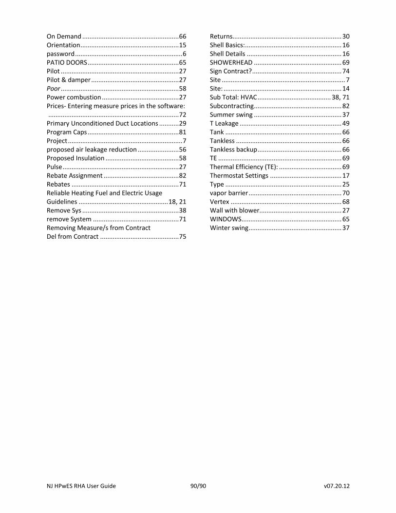
NJ HPwES RHA User Guide 90/90 v07.20.12
On Demand ...................................................... 66 Orientation ....................................................... 15 password ............................................................ 6 PATIO DOORS ................................................... 65 Pilot .................................................................. 27 Pilot & damper ................................................. 27 Poor .................................................................. 58 Power combustion ........................................... 27 Prices- Entering measure prices in the software: ......................................................................... 72 Primary Unconditioned Duct Locations ........... 29 Program Caps ................................................... 81 Project ................................................................ 7 proposed air leakage reduction ....................... 56 Proposed Insulation ......................................... 58 Pulse ................................................................. 27 Rebate Assignment .......................................... 82 Rebates ............................................................ 71 Reliable Heating Fuel and Electric Usage Guidelines .................................................. 18, 21 Remove Sys ...................................................... 38 remove System ................................................ 71 Removing Measure/s from Contract Del from Contract ............................................ 75
Returns............................................................. 30 Shell Basics: ...................................................... 16 Shell Details ..................................................... 16 SHOWERHEAD ................................................. 69 Sign Contract? .................................................. 74 Site ..................................................................... 7 Site: .................................................................. 14 Sub Total: HVAC ......................................... 38, 71 Subcontracting ................................................. 82 Summer swing ................................................. 37 T Leakage ......................................................... 49 Tank ................................................................. 66 Tankless ........................................................... 66 Tankless backup ............................................... 66 TE ..................................................................... 69 Thermal Efficiency (TE): ................................... 69 Thermostat Settings ........................................ 17 Type ................................................................. 25 vapor barrier .................................................... 70 Vertex .............................................................. 68 Wall with blower.............................................. 27 WINDOWS........................................................ 65 Winter swing .................................................... 37