Embed Size (px)
Citation preview

5th International Conference on Hydrogen SafetySeptember 9-11, 2013
Brussels, Bergium
ASAHARA, Makoto : Aoyama Gakuin University YOKOYAMA, Akinori : Aoyama Gakuin UniversityTATSUMI, Yuto : Aoyama Gakuin UniversityKATO, Suguru : Aoyama Gakuin UniversityYAMADA, Eisuke : Aoyama Gakuin Universit yHayashi, A.Koichi : Aoyama Gakuin University
REAL SIZE CALCULATION OF HIGH PRESSURE HYDROGEN FLOW AND ITS AUTO -IGNITION
IN CYLINDRICAL TUBE

Aerospace System Laboratory, Aoyama Gakuin University
Background (1)
Auto-ignition by diffusion is reported.
Mechanism and conditions of such diffusion ignition are not much known so far.
Needs safety standard for auto-ignition of high pressure hydrogen.
Development of Fuel Cell system.
Accidents at factories.
Increase of unknown H2 explosions due to an development of fuel cell car.
Why do we study H2 ignition? Recent accidents
HONDAFCX CLALITY
H2 TANK171 L
35 MPa

Aerospace System Laboratory, Aoyama Gakuin University
Background (2) Passed StudiesWolański and Wójcicki (1973)
Investigate the mechanism of the diffusion ignition of a combustible gasflowing into an oxidizing atmosphere.
Tanaka et al. (1979) Confirm the similar ignition.Uejima et al. (1998) Discuss the turbulent effects on the ignition.Liu et al. (2005), Bazhenova et al. (2005)
Calculate the hydrogen jet coming out to air at the room temperature.
Dryer et al. (2007), Pinto et al. (2007)Show the unique ignition potentials for pressurized releases of hydrogen.
Golub et al. (2008), Mogi et al. (2008), Yamada et al. (2008)Show the relationship between the pressure and the length of tube.
Xu et al. (2008)Discuss an auto-ignition would initiate inside the tube at the contact surface due tomass and energy exchange.
Mogi et al. (2009), Yamada et al.(2011), Kitabayashi et al.( 2012)
Kim et al. (2013)
Sandia National Laboratories (2003~)Investigate the hydrogen Release behavior
Aerospace System Laboratory, Aoyama Gakuin University
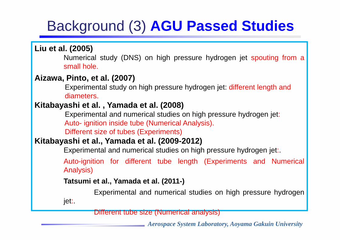
Background (3) AGU Passed StudiesLiu et al. (2005)
Numerical study (DNS) on high pressure hydrogen jet spouting from asmall hole.
Aizawa, Pinto, et al. (2007) CExperimental study on high pressure hydrogen jet: different length anddiameters.
Kitabayashi et al. , Yamada et al. (2008)Experimental and numerical studies on high pressure hydrogen jet:Auto- ignition inside tube (Numerical Analysis).Different size of tubes (Experiments)
Kitabayashi et al., Yamada et al. (2009-2012)Experimental and numerical studies on high pressure hydrogen jet:.
Auto-ignition for different tube length (Experiments and NumericalAnalysis)
Tatsumi et al., Yamada et al. (2011-)
Experimental and numerical studies on high pressure hydrogenjet:.
Different tube size (Numerical analysis)

Aerospace System Laboratory, Aoyama Gakuin University
Purpose
A real size numerical analysis
•Comparison with experiments.
•Validity of calculation using a detailed chemistry.
•Clarification of detailed auto -ignition mechanism.
Auto -ignition has not simulated at a real size level.
We do not know what happens in a real size tube numerically.
Numerical Analysis of High Pressure H 2 Ignition
Mogi et al. (2008)

Aerospace System Laboratory, Aoyama Gakuin University
◎◎◎◎Governing equations�2D axisymmetric and compressible Navier-Stokes
equations with species conservation equations�9 species (H2,O2,O,H,OH,HO2,H2O2,H2O,N2)
◎◎◎◎Discretization methods�Time integration:Strang type fractional step method�Convective term:2nd-order explicit Harten-Yee non-
MUSCL modified flux type TVD scheme
�Production term:Point implicit method
◎◎◎◎Detailed chemical reaction model�Petersen and Hanson model (1999)(P-H model)
Numerical Method

Aerospace System Laboratory, Aoyama Gakuin University
Numerical Conditions
◎Initial conditions (Hydrogen)
Burst pressure, MPa 2.0~~~~14.6
Temperature, K 300
AirH2 5mm
z
r
2D Axisymmetric
Half of computational region
These values are decided based on the experimental conditions by Kitabayashi, Mogi, and Kim et al.
◎Boundary conditionsLeft boundary: InflowRigh and their numbers are t boundary: OutflowWall boundaries: Adiabatic, non-slip
◎Initial conditions (Air)
Burst pressure, MPa 0.1
Temperature, K 300
Grid shape: square gridsGrid points:20001×1001,30001×501,
15001×251Grid sizes: 5µm,10µm, 20µm
◎Computational conditions100mm,300mm
10m
mH2Air
Aerospace System Laboratory, Aoyama Gakuin University
NUMERICAL RESULTS

Aerospace System Laboratory, Aoyama Gakuin University
Shock Wave Velocity
Agreement on shock wave velocity is in 20-30 % difference with the theoretical values and within 10 % with experimental values. This should certify the present numerical results.

Aerospace System Laboratory, Aoyama Gakuin University
Dependency of grid size on the resultsInitial burst pressure:14.6MPa
57mm
1.0××××107[1/s]-1.0××××107
0 2000[K]
0 1
Temp.
Vorticies
H2mass fraction
15mm
∆x=5µm
15mm
∆x=10µm ∆x=20µm
15mm

Aerospace System Laboratory, Aoyama Gakuin University
Time History of Temperature and OH Mass Fraction (Maximum values in the total numerical region)
Captured the phenomena in detail when grid size is smaller. 5µm grid gives the better results.

Aerospace System Laboratory, Aoyama Gakuin University
Time History of Temperature Profiles: 5µm grid
0 2500[K]
t
14 14 14 14 mm
5 m
m
2.63µs
5.49µs
9.75µs
14.0µs
19.7µs
25.1µs
30.7µs
36.3µs
41.7µs
47.2µs
52.8µs
58.4µs
63.9µs
69.5µs
75.2µs
81.1µs
86.8µs
91.1µs
H2 Air
Contact surface
Precusor shock
Compressible hot air
Reaction region

Aerospace System Laboratory, Aoyama Gakuin University
Time History of OH Mass Fraction: 5µm
2.63µs
5.49µs
9.75µs
14.0µs
19.7µs
25.1µs
30.7µs
36.3µs
41.7µs
47.2µs
52.8µs
58.4µs
63.9µs
69.5µs
75.2µs
81.1µs
86.8µs
91.1µs
t5
mm
14 14 14 14 mm
0 0.015
Vortices provide the contact surface fluctuation.
Expansion of reaction area.
Maintenance of autoignition

Aerospace System Laboratory, Aoyama Gakuin University
dx=dy=5µm. r=2.0mmTemperature and OH Profiles at certain radial position
PrecursorPrecursorPrecursorPrecursor
shockshockshockshock
ContactContactContactContact surfacesurfacesurfacesurface
(reaction(reaction(reaction(reaction area)area)area)area)
t=54.5µsTemperatureOH mass fraction
Reaction at contact surface
Temperature increase

Aerospace System Laboratory, Aoyama Gakuin University
Temperature Profiles at14.0µs
0 2500[K]
H2 Compressed air
Contact surface
1.0×10⁷[1/s]-1.0×107
Vorticity

Aerospace System Laboratory, Aoyama Gakuin University
Temperature Profiles at 19.7µs
0 2500[K]
0 1000[K]
Vorticity
1.0×10⁷[1/s]-1.0×107Vortices by K -H instability -1000 300[m/s]
y-Velocity

Aerospace System Laboratory, Aoyama Gakuin University
Pressure Profiles at 6.9~22.5µs
Production of compressible waves by vortices
Proceeding the deformation of contact surface

Aerospace System Laboratory, Aoyama Gakuin University
ConclusionsThe following results are obtained by calculating high pressure hydrogen auto-ignition in a tube:
� The validity of the present numerical analysis was certified by comparing the computed results with the passed experimental results since the numerical results agree with the experimental ones within 10 % differences.
� The fluctuation at the contact surface proceeds the mixing of hydrogen with air to yield auto-ignition.
� One of the causes of contact surface fluctuation is due to vortcies produced by K・H instability.
・It is necessary to calculate the cases changing tube length and diameter.
・3D calculation must be done to see the real physics in detail.

Aerospace System Laboratory, Aoyama Gakuin University
圧力分布履歴
管出口まで高圧・高温
を維持
0.1 1.2[MPa]
渦によって生じた
圧縮波による干渉
Aerospace System Laboratory, Aoyama Gakuin University
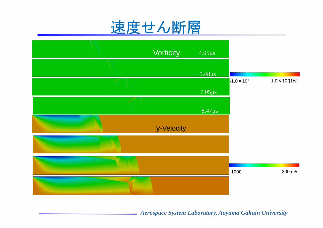
速度せん断層
4.05µs
5.48µs
7.05µs
8.47µs
1.0×10⁷[1/s]-1.0×107
300[m/s]-1000
y-Velocity
Vorticity

Numerical Analyses of Auto-Ignition using a Shock Tube
with a plunger system

Aerospace System Laboratory, Aoyama Gakuin University
Experimental Setup
High speed camera
H2
Plunger
Driver section
Oscilloscope
Extension shock tube
Pressure sensor
DiaphragmCoil
Needle
Trigger
Pressure sensor
Header tank
Shock Tube Length: L 100 ~ 4200 mm
Burst Pressure : Pb 2.0 ~ 8.0 MPa
Tube Diameter: D 10 mm
Experimental Conditions

Aerospace System Laboratory, Aoyama Gakuin University
Shock Tube

Aerospace System Laboratory, Aoyama Gakuin University
Shock Tube with a Plunger System
30mm
Pressure sensor
Pressure sensor
Iron core
Tungsten needle
30mm
Pressure sensor
Pressure sensor
Iron core
Tungsten needle

Aerospace System Laboratory, Aoyama Gakuin University
High Speed Camera

Aerospace System Laboratory, Aoyama Gakuin University
Pressure Profiles for Pb=4.8MPa Case
Pb=4.8MPaL=400mm
No Auto-Ignition

Aerospace System Laboratory, Aoyama Gakuin University
Pressure Wave ProfilesComparison pressure profiles at the pressure transducer located at 150 mm inside
from the tube exit for four different tube length cases at the condition of Pb=4.8MPa.
Shock Wave
Contact surface between hydrogen
and air
400mm
1200mm 1700mm
3200mm
1ms 1ms 1ms
Tube length
Auto-ignition
400mm ×
1200mm ○○○○
1700mm ×
3200mm ×
The pressure profile at the contact surface between air and hydrogen
becomes collapse for the longer tube.
Vortices exist at the contact surface
Auto-ignition occurred at the case of 1200 mm tube only.
There is a relation between the vortex and the shock wave strength.

Aerospace System Laboratory, Aoyama Gakuin University
Numerical Temperature Profiles (14.8 ms)
0 500 1000 1500 2000[K]
Vortices by K-H
instability0 3800 [m/s]
x-Velocity
H2
Air
H2Air
ShockContact Surface

Aerospace System Laboratory, Aoyama Gakuin University
0
500
1000
1500
0.0 2.0 4.0 6.0 8.0 10.0
Pre
ssu
re w
av
e v
elo
city
, m
/s
Burst pressure, MPa
TheoryExp. (300~400mm)Exp. (650mm)Exp. (2.2~3.2m)Mogi et al.(2009)
Shock VelocityThe relation between burst pressure and shock velocity at thetube length of 300, 400, 650 mm and 2.2, 3.2 m.
•The theory and experiments are in the same tendency.
•The diaphragm breaks in a finite time and 3D way.
•The boundary layer effect.
•The similar tendency as theory. (200 m/s below)
•The same results as the old study for the short tube (300-600 mm)
•The 400 m/s lower than theory for the long tube (2.2-3.2 m)

Aerospace System Laboratory, Aoyama Gakuin University
Auto-Ignition Limit Curve(Tube Length of up to 700mm)
0
2
4
6
8
10
12
14
0 100 200 300 400 500 600 700
Bur
st p
ress
ure,
MP
a
Tube length, mm
Successful ignition (Plunger) Failed-ignition (Plunger)Non-ignition (Plunger) Successful ignition (Press. increasing)Failed-ignition (Press. increasing) Non-ignition (Press. incresing)Successful ignition (Mogi, 2009) Failed-ignition (Mogi, 2009)Non-ignition (Mogi, 2009) Successful ignition (Pinto[AGU], 2007)Non-ignition (Pinto[AGU], 2007) Successful ignition (Golub, 2008)Non-ignition (Golub, 2008)

Aerospace System Laboratory, Aoyama Gakuin University
0
2
4
6
8
10
12
14
0 1000 2000 3000 4000
Bur
st p
ress
ure,
MP
a
Tube length, mm
Auto-Ignition Limit Curve
Mogi et al.
This work
Pinto et al.
○ Successful ignition
△ Failed-ignition
× Non-ignition
Auto-ignition curve has a minimum.
Hydrogen can be released safely using
a long tube.
Experiments were performed at the constant
burst pressure
Data were obtained repeatedly.

Aerospace System Laboratory, Aoyama Gakuin University
High-Speed Movie Data
Focus Distance
100 mm
F-Number 3.5
Frame Speed
60000 fps
Tube Diameter
500 mm
Burst Pressure
4.8 MPa

Aerospace System Laboratory, Aoyama Gakuin University
Sustainable and Non-Sustainable Auto-Ignition
D=5 mmL=185 mmPb=14.5 MPa
(a) Sustainable combustion case
300 µs50 µs0 µs 100 µs
(b) Non-sustainable combustion case
D=5 mmL=185 mmPb=11.6 MPa
166 µs33 µs0 µs 100 µs
Mogi et al. (2008)
・・・・High pressure・・・・Long Tube Easier to ignite (2008)

Aerospace System Laboratory, Aoyama Gakuin University
Mach Disc in Under-Expansion Supersonic Nozzle

Aerospace System Laboratory, Aoyama Gakuin University
Detailed Photos
Took a high speed movie near the tube exit
0 µs
10 µs
20 µs
30 µs
40 µs
50 µs
60 µs
70 µs
80 µs
90 µs
100 µs
110 µs
Mach disc Outer edge of jet
20 m
m
Auto-ignition
inside tube
Focal length
105 mm
Focal number
2.8
Shutter speed
100000 fps
Tube length
650 mm
Burst pressure
5.0 MPa
•Saw the auto-ignition inside of the tube.
•Recognized the phenomena of supersonic jet.

Aerospace System Laboratory, Aoyama Gakuin University
Conclusion
Experiments of Auto-Ignition using a Shock Tube with a plunger system
Obtained the clear auto-ignition limit curve by experimenting the shock wave with a control of burst pressure.Found that no auto-ignition with an enough length of tube.Observed auto-ignition in tube.