Embed Size (px)
Citation preview
COMPUTERS IN EDUCATION JOURNAL 85
REAL-TIME 3D RECONSTRUCTION FOR FACILITATING THE DEVELOPMENT OF GAME-BASED VIRTUAL LABORATORIES
Zhou Zhang, Mingshao Zhang, Yizhe Chang, Sven K. Esche, Constantin Chassapis
School of Engineering and Science Stevens Institute of Technology
Abstract
Game-based virtual laboratories (GBVLs)
represent an important implementation of virtual reality and are often considered to be simulations of real or artificial environments. They are based on 2D/3D graphics and built using a specific game engine. GBVLs are becoming increasingly popular at various levels of education. In addition to designing the story plot and game logic, other essential tasks during the creation of GBVLs are to virtualize the real world and to insert all of the virtual representations of the real objects into the GBVLs’ environments. The traditional method for virtualizing real objects is to design the models of these objects with some CAD software and then to convert these models to the model format of the GBVL. In creating these models, one needs to not only measure the real objects but also to draw their features. These processes are tedious and time-consuming, thus considerably limiting the potential application and popularization of GBVLs.
This paper introduces a series of novel
procedures for creating virtual representations of real objects based on 3D reconstruction techniques. During these procedures, one hand-held depth camera is used to scan the real objects. First, the tracing of the pose of the camera is discussed. Then, the processing methods for the captured raw data are covered, and based on the processed data, the registration of the shape information of the model is discussed. Subsequently, a method for recognizing the scanned object is presented. Finally, the generation of the final model file for GBVLs is described. In order to validate this method, a prototype GBVL used in an undergraduate engineering course was designed and implemented. Through a comparison
between the traditional methods and the proposed procedures, it was demonstrated that the latter significantly sped up the process of creating virtual laboratory implementations.
Introduction
Although the concept of virtual reality (VR)
has not been universally defined, VR is used to represent the real world by a computer-simulated virtual representation of it. [1] Many forms of VR can be found at present, and they can be divided into four main types: desktop VR, immersive VR, distributed VR and augmented VR. In the environment of VR, multiple users can manipulate and share the virtual representations of the real world. At the same time, they can also cooperate with each other. VR systems are inherently safer and less failure prone than their physical equivalents. Therefore, VR is very appropriate to be taken as an alternative solution for dangerous and costly training programs (e.g., firefighter training, military training, disaster relief training, new-employee training, etc.). In addition, VR can conserve most of the human and material resources, and it can make them accessible remotely for the participants. Thus, it is a good candidate for the development of virtual education systems. Among the various implementations of virtual education systems, virtual laboratories are used at various levels of education, ranging from the education at elementary schools to the education at universities [2,3].
GBVLs that aim to provide the learners with a
feeling of immersion and to increase their learning interest have recently been reported [4,5,6]. Such GBVLs are often based on multi-player computer game engines, which
86 COMPUTERS IN EDUCATION JOURNAL
provide various basic ready-to-use functions such as physics modeling, graphics rendering, sound generation, game logics, artificial intelligence, user interactions and networking. These capabilities of game engines enable the design and implementation of immersive, distributed and collaborative GBVLs. One of the important advantages of GBVLs is that the users can create their own models, avatars and other virtual features. This advantage makes GBVLs extensible and customizable [9].
Although the attribute of customization of
GBVLs is attractive for both developers and users, the virtualization of the real world remains a very tedious task. Firstly, the objects in the real world must be measured in order to obtain all of the necessary geometric parameters. Then, the built-in toolkits of the game engine or third-party 3D software need to be employed to create computer models of the real objects. Finally, the models created following the steps outlined above must be converted into the ready-to-use format of the specific game engine used. It is an undeniable fact that the process of virtualizing artifacts of the real world is time-consuming and requires patience. Therefore, the efficiency of building a GBVL could be improved dramatically if the models could be generated in real-time by the method of 3D reconstruction.
3D reconstruction is a method for creating a
model of an object by scanning its surface with one or multiple scanners. The 3D reconstruction procedure can be divided into several steps: obtaining the surface data of real objects using a scanner, processing the raw surface data, generating an improved point cloud and creating the final model. The models can be stored in any valid 3D model type. Then, they are imported into and rendered in the specific virtual platform. Among the various procedures involved in the reconstruction of real-world artifacts, the acquisition and processing of the shape information are the most important [10].
Although 3D reconstruction techniques have
been investigated for many years, their potential for deployment in various fields of application
(e.g., medical applications [11] and archaeological research [12], recovery of 3D shapes of deformable surfaces [13]) makes them a topic of ongoing research. With the development of structured light cameras (laser scanners and infrared cameras, etc.), 3D reconstruction techniques have been improving quickly recently. Many innovative applications of 3D reconstruction have been reported, for instance the reconstruction of 3D faces of people [14], 3D voxel reconstruction of human motions [15] and the reconstruction of urban scenes from videos [16]. There are two main approaches for obtaining the shape information of real objects. The first method is to register the surface information of these real objects by dynamic scanning devices. For instance, ‘ReconstructMeQt’ can be used to build 3D surfaces with a Kinect and to export 3D surface files to other software [17]. The second method is to retrieve the surface information from 2D still images. For instance, ‘3DSOM Pro’ [18] and ‘insight3d’ [19] can be utilized to produce 3D models through a series of alignment pictures. The ‘KinectFusion’ is one of the most interesting 3D reconstruction applications. In conjunction with a ‘Microsoft Kinect for Windows’, it can serve to acquire the shape information of objects and then to process the raw data to generate the corresponding 3D models in real time [20,21]. Such a method for generating 3D models in real time can then be applied to build the models used in a GBVL.
Besides the creation of the models, it is also
very useful to segment and recognize the scanned scenarios. Suppose that during scanning, many experimental tools are laid out on a table. They would often be abutting or overlapping when being observed from different view orientations. A straightforward method for creating computer models of the objects would be to pick up the objects one at a time and to scan them separately. Obviously, this approach would not be convenient when there are too many individual objects to be scanned. Therefore, it becomes important to segment the images before creating them.
COMPUTERS IN EDUCATION JOURNAL 87
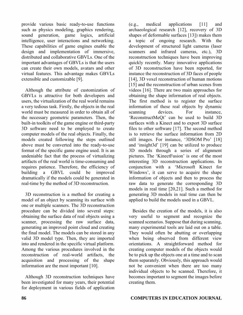
The GBVL presented here was created based on Garry’s Mod (GMod). As a modification of the ‘Source’ game engine, GMod has been developed into a user-friendly multi-player computer game platform which enables users to create their own plug-ins, to program their own features with G_LUA and to design and implement their own stories [22,23]. In addition, GMod has all of the characteristics of general game engines such as graphics rendering, sound generation, physics modeling, game logics, artificial intelligence, user interactions and networking [7]. These basic functions can facilitate the development of GBVLs. Each game engine requires a specific model format. Therefore, a specific GBVL is implemented based on a specific modeling approach. The conventional method used to build models of physical artifacts in GMod can be divided into the following steps: (i) obtain the geometric parameters of the real objects, (ii) plot the models of the real objects with built-in tools such as ‘Hammer’ [24] or third-party software such as ‘3ds Max’, (iii) convert the models into ‘StudioMDL’ [25] data (SMD) files, (iv) use ‘VTFEdit’ to generate VTF texture files and (v) use ‘GUIStuidoMDL’ to compile SMD and VTF textures into models that are ready to be used in GMod. SMD files store 3D models in ASCII format for analysis and compilation by ‘StudioMDL’. The contents of SMD files mainly include the vertex and texture information of the models. Figure 1 illustrates the conventional modeling process of GBVLs in Garry’s Mod. It
also shows that the laborious work is to measure real objects and create the corresponding models in ‘3ds Max’.
Real-time Creation of Game Models
Necessary Improvements for the Conventional Modeling Process
The conventional modeling process as shown
in Figure 1 involves complicated procedures. The objects are measured by some measuring tools, and at the same time, pictures of the object surfaces are taken. Then, the parameters are imported into 3D software to create models, and the pictures are converted to textures in order to be attached to the surface of the models. Last, the combination of models and textures are converted to MDL models, which can be recognized by GMod. Thus, this method has several natural shortcomings, namely it is laborious, time consuming, costly and complicated. Therefore, the simplification of the process and shortening of the processing time are the main objectives, and real-time modeling can realize these objects.
The realization of real-time modeling depends
on the method of acquiring the geometric parameters and the processing of this information. Therefore, the first task is to identify a sensor to replace the traditional measuring devices, and the second task is to
Figure 1: Conventional modeling process of GBVLs in Garry’s Mod.
88 COMPUTERS IN EDUCATION JOURNAL
develop a special tool for processing the obtained raw data of objects to automatically generate the corresponding models that are ready to be used in the game. Alternative Measuring Device Selection
As an alternative method for obtaining the geometric parameters of objects, various kinds of scanners are employed widely, including 3D depth scanners and 2D scanners. Based on their operating principles, 3D depth scanners are divided into laser depth scanners and infrared depth scanners. Laser depth scanners are often used in high accuracy and high resolution applications [26], and infrared depth scanners are commonly favored in less demanding applications [27]. 2D scanners often are simply common cameras, which can be used in applications whose requirements for both accuracy and real-time suitability are not too strict [28]. The main disadvantage of common cameras is that they can only acquire 2D information of the object of interest. This means that much more complicated algorithms are required, which in turn prolongs the modeling time dramatically. Thus, 3D depth scanners are more appropriate than common cameras for realizing real-time modeling. On the other hand, laser depth scanners are usually very expensive, and their operation also requires a certain amount of professional knowledge. Infrared scanners, of which the Microsoft Kinect is a representative, are much more affordable and much more accessible and flexible as compared with laser depth scanners, even though they are somewhat more expensive than common cameras. It should be noted that the Kinect has been used for instance as a data acquisition device in laboratory environments [29,30].
As a popular entertainment medium, computer
games have their own attraction and specific characteristics. In educational game environments, figures and clues are used primarily to submerge players into the game world. These features of games are often idealized or conceptualized. Hence, instead of focusing on the precision of the models, the
players simply enjoy the game playing process. Although highly accurate models can improve GBVLS, their accuracy does not, in fact, affect the function of the GBVLs significantly. Thus, when taking into consideration the cost of the device, the efficiency of the modeling and the attributes of the games, the Kinect becomes a true alternative for replacing the traditional measuring tools for acquiring geometric information of real objects.
The Microsoft Kinect for Windows sensor was
designed for devices and computers running the Windows operating system. It can also be used with Windows embedded-based devices. The Kinect is composed of an accelerometer, a structured light projector, a microphone array and two sensors (cameras), namely an ‘infrared (IR) depth sensor’ and a ‘color (RGB)’ sensor. The IR sensor captures the depth information of the object with a resolution of up to 640×480 in pixels while the color sensor captures the color information of the object with a resolution of up to 1280×960 in pixels [31,32]. The absolute error of the depth values is more than 1 mm, which implies that the accuracy of the models created with the Kinect is more than 1 mm. Therefore, the accuracy of the Kinect is not comparable with accurate scanning tools such as laser scanners. The obvious advantages of the Kinect, as described above, are its affordability and its user-friendliness. In order to enable users to extend the function of the Kinect, Microsoft publishes a software development kit (SDK) and developer toolkits. The Kinect for Windows SDK and developer toolkits include device drivers, development tools, development APIs, device interfaces and code samples. This SDK is updated frequently, and future updates are expected to add improvements for more control and deeper access to sensor data. Nowadays, the usage of the Kinect is becoming more and more popular and convenient because of the introduction of these SDKs.
COMPUTERS IN EDUCATION JOURNAL 89
Feasibility of Automatic Real-time Model Creation for GBVLs
The Kinect can be used as a sensor for scanning real objects in two ways: either by moving the Kinect relative to the object to be scanned or by moving the object relative to the Kinect [33]. The former method is more flexible and more failsafe than the latter method, even though the pose of the Kinect must be tracked. In the work described here, one hand-held Kinect was used to acquire the data. Thus, after acquiring the raw data of the objects, the pose of the Kinect is tracked. This can be realized by a fast stereo matching algorithm [34]. Then, a 3D point cloud of the object can be obtained once the coordinates of the Kinect have been determined. The next problem to be solved is to mesh the 3D point cloud and attach the corresponding texture to every mesh element. If the number of mesh elements and the resolution of the textures are limited, then the processing time of modeling can be kept at a reasonable level. The shape information contained in the SMD files is stored with the triangular mesh elements, and therefore, the SMD files can be generated simultaneously if the 3D point cloud is meshed with triangles. Both ‘VTFEdit’ (the conversion tool for textures) and ‘GUIStudioMDL’ (the compilation tool) also have executable files in ‘command prompt’ format. Thus, by using the API provided by the Windows shell, the above two executable files
can be executed automatically [35] Therefore, it is feasible to realize real-time modeling automatically.
Acquisition of Shape Information and Processing of Objects
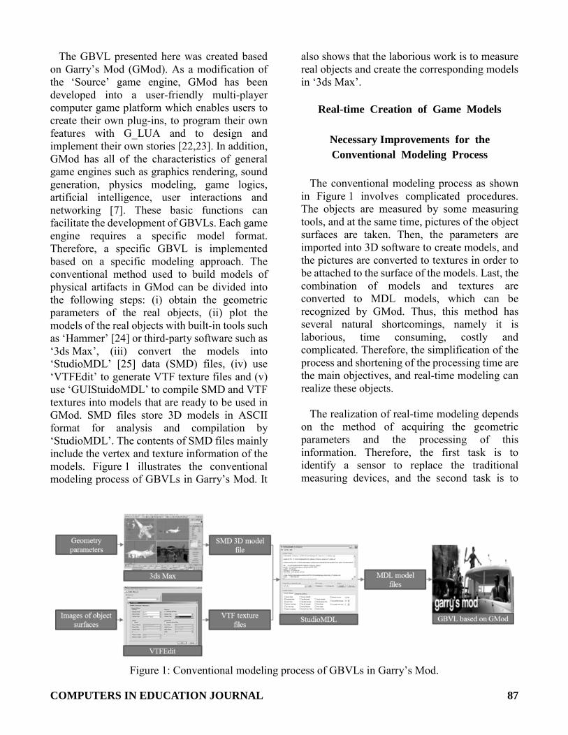
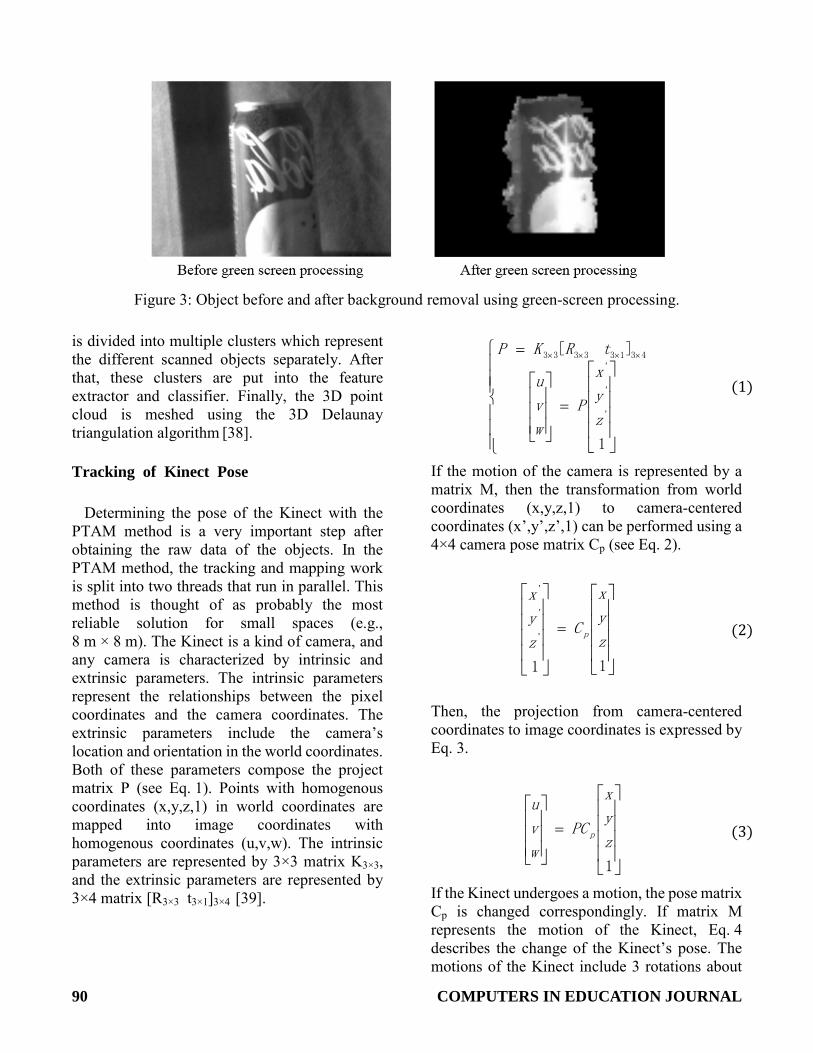
The main procedures of data acquisition and processing are depicted in Figure 2. As illustrated in this flow chart, the green-screen technique is used to extract the useful information of the objects from the background which is of uniform color and shade [36]. This approach reduces the time required for matching the images and saves storage space because of the reduction of the amount of data to be processed. Figure 3 shows an object before and after the background information has been removed by green-screen processing. In this figure, the green background has been replaced by black.
A set of sequential color frames is used to
determine the pose of the Kinect using the ‘parallel tracking and mapping’ (PTAM) method
[37] After obtaining the 3D point cloud, there are two different operations based on the objects’ occlusion conditions. If there are no occlusions, the 3D point cloud is directly transferred to a feature extractor and classifier for classification. If the objects occlude each other, segmentation must be implemented. Then, the 3D point cloud
Figure 2: Flow chart of data acquisition and processing.
90 COMPUTERS IN EDUCATION JOURNAL
Figure 3: Object before and after background removal using green-screen processing.
is divided into multiple clusters which represent the different scanned objects separately. After that, these clusters are put into the feature extractor and classifier. Finally, the 3D point cloud is meshed using the 3D Delaunay triangulation algorithm [38].
Tracking of Kinect Pose
Determining the pose of the Kinect with the PTAM method is a very important step after obtaining the raw data of the objects. In the PTAM method, the tracking and mapping work is split into two threads that run in parallel. This method is thought of as probably the most reliable solution for small spaces (e.g., 8 m × 8 m). The Kinect is a kind of camera, and any camera is characterized by intrinsic and extrinsic parameters. The intrinsic parameters represent the relationships between the pixel coordinates and the camera coordinates. The extrinsic parameters include the camera’s location and orientation in the world coordinates. Both of these parameters compose the project matrix P (see Eq. 1). Points with homogenous coordinates (x,y,z,1) in world coordinates are mapped into image coordinates with homogenous coordinates (u,v,w). The intrinsic parameters are represented by 3×3 matrix K3×3, and the extrinsic parameters are represented by 3×4 matrix [R3×3 t3×1]3×4 [39].
=
= ××××
1
][
'
'
'
43133333
z
y
x
P
w
v
u
tRKP
(1)
If the motion of the camera is represented by a matrix M, then the transformation from world coordinates (x,y,z,1) to camera-centered coordinates (x’,y’,z’,1) can be performed using a 4×4 camera pose matrix Cp (see Eq. 2).
=
11
'
'
'
z
y
x
Cz
y
x
p (2)
Then, the projection from camera-centered coordinates to image coordinates is expressed by Eq. 3.
=
1
z
y
x
PC
w
v
u
p (3)
If the Kinect undergoes a motion, the pose matrix Cp is changed correspondingly. If matrix M represents the motion of the Kinect, Eq. 4 describes the change of the Kinect’s pose. The motions of the Kinect include 3 rotations about
COMPUTERS IN EDUCATION JOURNAL 91
the 3 axes and 3 translations along the 3 axes. Thus, they can be expressed by a 6-dimensional vector vm using the exponential map of Eq. 4 [40]. Once vm has been determined, the pose of the Kinect can be obtained.
The procedures for tracking the pose of the
Kinect were described in detail elsewhere [37].
pv
pp CeMCC m=='
(4)
3D Point Cloud Generation and Triangular Meshing
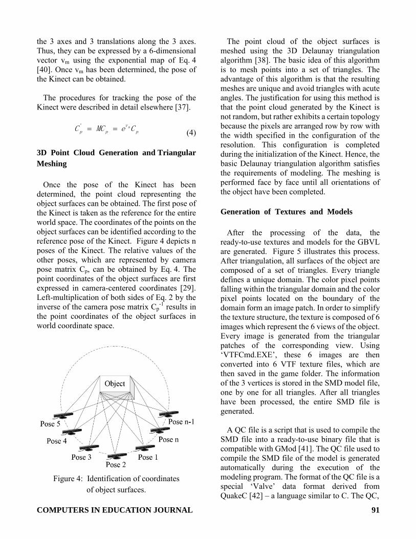
Once the pose of the Kinect has been determined, the point cloud representing the object surfaces can be obtained. The first pose of the Kinect is taken as the reference for the entire world space. The coordinates of the points on the object surfaces can be identified according to the reference pose of the Kinect. Figure 4 depicts n poses of the Kinect. The relative values of the other poses, which are represented by camera pose matrix Cp, can be obtained by Eq. 4. The point coordinates of the object surfaces are first expressed in camera-centered coordinates [29]. Left-multiplication of both sides of Eq. 2 by the inverse of the camera pose matrix Cp
-1 results in the point coordinates of the object surfaces in world coordinate space.
Figure 4: Identification of coordinates
of object surfaces.
The point cloud of the object surfaces is meshed using the 3D Delaunay triangulation algorithm [38]. The basic idea of this algorithm is to mesh points into a set of triangles. The advantage of this algorithm is that the resulting meshes are unique and avoid triangles with acute angles. The justification for using this method is that the point cloud generated by the Kinect is not random, but rather exhibits a certain topology because the pixels are arranged row by row with the width specified in the configuration of the resolution. This configuration is completed during the initialization of the Kinect. Hence, the basic Delaunay triangulation algorithm satisfies the requirements of modeling. The meshing is performed face by face until all orientations of the object have been completed.
Generation of Textures and Models
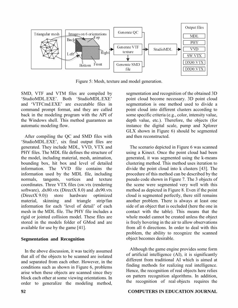
After the processing of the data, the ready-to-use textures and models for the GBVL are generated. Figure 5 illustrates this process. After triangulation, all surfaces of the object are composed of a set of triangles. Every triangle defines a unique domain. The color pixel points falling within the triangular domain and the color pixel points located on the boundary of the domain form an image patch. In order to simplify the texture structure, the texture is composed of 6 images which represent the 6 views of the object. Every image is generated from the triangular patches of the corresponding view. Using ‘VTFCmd.EXE’, these 6 images are then converted into 6 VTF texture files, which are then saved in the game folder. The information of the 3 vertices is stored in the SMD model file, one by one for all triangles. After all triangles have been processed, the entire SMD file is generated.
A QC file is a script that is used to compile the
SMD file into a ready-to-use binary file that is compatible with GMod [41]. The QC file used to compile the SMD file of the model is generated automatically during the execution of the modeling program. The format of the QC file is a special ‘Valve’ data format derived from QuakeC [42] – a language similar to C. The QC,
92 COMPUTERS IN EDUCATION JOURNAL
Figure 5: Mesh, texture and model generation.
SMD, VTF and VTM files are compiled by ‘StudioMDL.EXE’. Both ‘StudioMDL.EXE’ and ‘VTFCmd.EXE’ are executable files in command prompt format, and they are called back in the modeling program with the API of the Windows shell. This method guarantees an automatic modeling flow.
After compiling the QC and SMD files with
‘StudioMDL.EXE’, six final output files are generated. They include MDL, VVD, VTX and PHY files. The MDL file defines the structure of the model, including material, mesh, animation, bounding box, hit box and level of detailed information. The VVD file contains the information used by the MDL file, including normals, tangents, vertices and texture coordinates. Three VTX files (sw.vtx (rendering software), .dx80.vtx (DirectX 8.0) and .dx90.vtx (DirectX 9.0)) store hardware optimized material, skinning and triangle strip/fan information for each ‘level of detail’ of each mesh in the MDL file. The PHY file includes a rigid or jointed collision model. These files are stored in the models folder of GMod and are available for use by the game [41].
Segmentation and Recognition
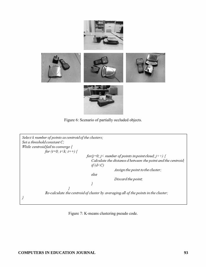
In the above discussion, it was tacitly assumed that all of the objects to be scanned are isolated and separated from each other. However, in the conditions such as shown in Figure 6, problems arise when these objects are scanned since they block each other at some viewing orientations. In order to generalize the modeling method,
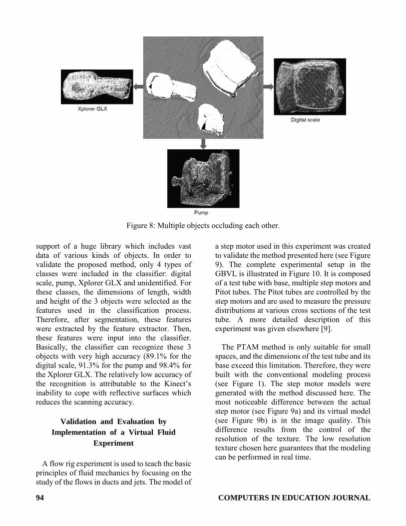
segmentation and recognition of the obtained 3D point cloud become necessary. 3D point cloud segmentation is one method used to divide a point cloud into different clusters according to some specific criteria (e.g., color, intensity value, depth value, etc.). Therefore, the objects (for instance the digital scale, pump and Xplorer GLX shown in Figure 6) should be segmented and then reconstructed.
The scenario depicted in Figure 6 was scanned
using a Kinect. Once the point cloud had been generated, it was segmented using the k-means clustering method. This method uses iteration to divide the point cloud into k clusters [43]. The procedure of this method can be described by the pseudo code shown in Figure 7. The 3 objects of the scene were segmented very well with this method as depicted in Figure 8. Even if the point cloud is segmented perfectly, there still remains another problem. There is always at least one side of an object that is occluded (here the one in contact with the table). This means that the whole model cannot be created unless the object is freely hovering in the air to allow observations from all 6 directions. In order to deal with this problem, the ability to recognize the scanned object becomes desirable.
Although the game engine provides some form
of artificial intelligence (AI), it is significantly different from traditional AI which is aimed at finding methods for realizing real intelligence. Hence, the recognition of real objects here relies on pattern recognition algorithms. In addition, the recognition of real objects requires the
COMPUTERS IN EDUCATION JOURNAL 93
Figure 6: Scenario of partially occluded objects.
Figure 7: K-means clustering pseudo code.
94 COMPUTERS IN EDUCATION JOURNAL
Figure 8: Multiple objects occluding each other.
support of a huge library which includes vast data of various kinds of objects. In order to validate the proposed method, only 4 types of classes were included in the classifier: digital scale, pump, Xplorer GLX and unidentified. For these classes, the dimensions of length, width and height of the 3 objects were selected as the features used in the classification process. Therefore, after segmentation, these features were extracted by the feature extractor. Then, these features were input into the classifier. Basically, the classifier can recognize these 3 objects with very high accuracy (89.1% for the digital scale, 91.3% for the pump and 98.4% for the Xplorer GLX. The relatively low accuracy of the recognition is attributable to the Kinect’s inability to cope with reflective surfaces which reduces the scanning accuracy.
Validation and Evaluation by
Implementation of a Virtual Fluid Experiment
A flow rig experiment is used to teach the basic
principles of fluid mechanics by focusing on the study of the flows in ducts and jets. The model of
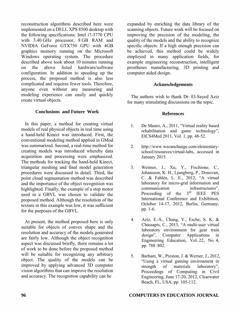
a step motor used in this experiment was created to validate the method presented here (see Figure 9). The complete experimental setup in the GBVL is illustrated in Figure 10. It is composed of a test tube with base, multiple step motors and Pitot tubes. The Pitot tubes are controlled by the step motors and are used to measure the pressure distributions at various cross sections of the test tube. A more detailed description of this experiment was given elsewhere [9].
The PTAM method is only suitable for small
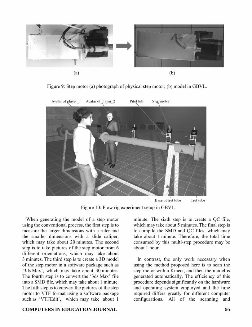
spaces, and the dimensions of the test tube and its base exceed this limitation. Therefore, they were built with the conventional modeling process (see Figure 1). The step motor models were generated with the method discussed here. The most noticeable difference between the actual step motor (see Figure 9a) and its virtual model (see Figure 9b) is in the image quality. This difference results from the control of the resolution of the texture. The low resolution texture chosen here guarantees that the modeling can be performed in real time.
COMPUTERS IN EDUCATION JOURNAL 95
(a) (b)
Figure 9: Step motor (a) photograph of physical step motor; (b) model in GBVL.
Figure 10: Flow rig experiment setup in GBVL.
When generating the model of a step motor
using the conventional process, the first step is to measure the larger dimensions with a ruler and the smaller dimensions with a slide caliper, which may take about 20 minutes. The second step is to take pictures of the step motor from 6 different orientations, which may take about 3 minutes. The third step is to create a 3D model of the step motor in a software package such as ‘3ds Max’, which may take about 30 minutes. The fourth step is to convert the ‘3ds Max’ file into a SMD file, which may take about 1 minute. The fifth step is to convert the pictures of the step motor to VTF format using a software package such as ‘VTFEdit’, which may take about 1
minute. The sixth step is to create a QC file, which may take about 5 minutes. The final step is to compile the SMD and QC files, which may take about 1 minute. Therefore, the total time consumed by this multi-step procedure may be about 1 hour.
In contrast, the only work necessary when
using the method proposed here is to scan the step motor with a Kinect, and then the model is generated automatically. The efficiency of this procedure depends significantly on the hardware and operating system employed and the time required differs greatly for different computer configurations. All of the scanning and
96 COMPUTERS IN EDUCATION JOURNAL
reconstruction algorithms described here were implemented on a DELL XPS 8500 desktop with the following specifications: Intel i7-3770 CPU with 3.40 GHz processor, 8 GB RAM and NVIDIA GeForce GTX750 GPU with 4GB graphics memory running on the Microsoft Windows operating system. The procedure described above took about 10 minutes running on the above listed hardware/software configuration. In addition to speeding up the process, the proposed method is also less complicated and requires fewer tools. Therefore, anyone even without any measuring and modeling experience can easily and quickly create virtual objects.
Conclusions and Future Work
In this paper, a method for creating virtual
models of real physical objects in real time using a hand-held Kinect was introduced. First, the conventional modeling method applied in GMod was summarized. Second, a real-time method for creating models was introduced whereby data acquisition and processing were emphasized. The methods for tracking the hand-held Kinect, triangular meshing and final model generation procedures were discussed in detail. Third, the point cloud segmentation method was described and the importance of the object recognition was highlighted. Finally, the example of a step motor used in a GBVL was chosen to validate the proposed method. Although the resolution of the texture in this example was low, it was sufficient for the purposes of the GBVL.
At present, the method proposed here is only
suitable for objects of convex shape and the resolution and accuracy of the models generated are fairly low. Although the object recognition aspect was discussed briefly, there remains a lot of work to be done before the proposed method will be suitable for recognizing any arbitrary object. The quality of the models can be improved by applying advanced 3D computer vision algorithms that can improve the resolution and accuracy. The recognition capability can be
expanded by enriching the data library of the scanning objects. Future work will be focused on improving the precision of the modeling, the quality of the models and the ability to recognize specific objects. If a high enough precision can be achieved, this method could be widely employed in many application fields, for example engineering reconstruction, intelligent prostheses manufacturing, 3D printing and computer aided design.
Acknowledgements
The authors wish to thank Dr. El-Sayed Aziz
for many stimulating discussions on the topic.
References
1. De Mauro, A., 2011, “Virtual reality based rehabilitation and game technology”, EICS4Med 2011, Vol. 1, pp. 48-52.
2. http://www.wecanchange.com/elementary-
school/resources/virtual-labs, accessed in January 2015.
3. Weimer, J., Xu, Y., Fischione, C.,
Johansson, K. H., Ljungberg, P., Donovan, C. & Fahlén, L. E., 2012, “A virtual laboratory for micro-grid information and communication infrastructures”, Proceeding of the 3rd IEEE PES International Conference and Exhibition, October 14-17, 2012, Berlin, Germany, pp. 1-6.
4. Aziz, E.-S., Chang, Y., Esche, S. K. &
Chassapis, C., 2013, “A multi-user virtual laboratory environment for gear train design”, Computer Applications in Engineering Education, Vol. 22, No. 4, pp. 788–802.
5. Barham, W., Preston, J. & Werner, J., 2012,
“Using a virtual gaming environment in strength of materials laboratory”, Proceedings of Computing in Civil Engineering, June 17-20, 2012, Clearwater Beach, FL, USA, pp. 105-112.
COMPUTERS IN EDUCATION JOURNAL 97
6. http://www.virtualgamelab.com, accessed in January 2015.
7. Baba, S. A., Hussain, H. & Embi, Z. C.,
2007, “An overview of parameters of game engine”, IEEE Multidisciplinary Engineering Education Magazine, Vol. 2, No. 3, pp. 10-12.
8. Thorn, A., 2010, “Game Engine Design
and Implementation”, Chapter 1, 1st Ed., Jones & Bartlett Publishers.
9. Zhang, Z., Zhang, M., Tumkor, S., Chang,
Y., Esche, S. K. & Chassapis, C., 2013, “Integration of physical devices into game-based virtual reality”, International Journal of Online Engineering, Vol. 9, No. 5, pp. 25-38.
10. Mouragnon, E., Lhuillier, M., Dhome, M.,
Dekeyser, F. & Sayd, P., 2006, “Real time localization and 3D reconstruction”, Proceedings of the 2006 IEEE Conference on Computer Vision and Pattern Recognition, New York, NY, USA, June 17-22, 2006, Vol. 1, pp. 363-370.
11. Hibbard, L. S., Grothe, R. A.,
Arnicar-Sulze, T. L., Dovey-Hartman, B. J. & Page, R. B., 1993, “Computed three-dimensional reconstruction of median eminence capillary modules”, Journal of Microscopy, Vol. 171, pp. 39-56.
12. Fiz, I. & Orengo, H. A., 2007, “The
application of 3D reconstruction techniques in the analysis of ancient Tarraco’s urban topography”, Proceeding of the 35th International Conference on Computer Applications and Quantitative Methods in Archaeology, Berlin, Germany, April 2-6, 2007.
13. Varol, A., Shaji, A., Salzmann, M. & Fua,
P., 2012, “Monocular 3D reconstruction of locally textured surfaces”, IEEE Transactions of Pattern Analysis and Machine Intelligence, Vol. 34, No. 6, pp. 1118-1130.
14. Choi, J., Medioni, G., Lin, Y., Silva, L., Regina, O., Pamplona, M. & Faltemier, T. C., 2010, “3D face reconstruction using a single or multiple views”, Proceeding of International Conference on Pattern Recognition, Istanbul, Turkey, August 23-26, 2010.
15. Cheung, G. K., Kanade, T., Bouguet, J. Y.
& Holler, M., 2000, “A real time system for robust 3D voxel reconstruction of human motions”, Proceedings of the 2000 IEEE Conference on Computer Vision and Pattern Recognition, June 13-15, 2000, Hilton Head, SC, USA.
16. Pollefeys, M. et al., 2008, “Detailed
real-time urban 3D reconstruction from video”, International Journal of Computer Vision, Vol. 78, No. 2, pp. 143-167.
17. http://reconstructme.net/projects/reconstru
ctmeqt, accessed in January 2015. 18. http://www.3dsom.com/, accessed in
January 2015. 19. http://insight3d.sourceforge.net, accessed
in January 2015. 20. http://msdn.microsoft.com/en-us/library/d
n188670.aspx, accessed in January 2015. 21. Izadi, S., Kim, D., Hilliges, O., Molyneaux,
D., Newcombe, R. A., Kohli, P., Shotton, J., Hodges, S., Freeman, D., Davison, A. J. & Fitzgibbon, A. W., 2011, “KinectFusion: real-time 3D reconstruction and interaction using a moving depth camera”, Proceedings of the 24th Annual ACM Symposium on User Interface Software and Technology, Santa Barbara, CA, USA, October 16-19, 2011, pp. 559-568.
22. http://garrysmod.com/, accessed in January
2015. 23. http://source.valvesoftware.com/, accessed
in January 2015.
98 COMPUTERS IN EDUCATION JOURNAL
24. https://developer.valvesoftware.com/wiki/Valve_Hammer _Editor, accessed in January 2015.
25. https://developer.valvesoftware.com/wiki/
Studiomdl_Data, accessed in January 2015.
26. Hoffman, A., Goetz, M., Vieth, M., Galle,
P. R., Neurath, M. F. & Kiesslich, R., 2006, “Confocal laser endomicroscopy: technical status and current indications”, Endoscopy, Vol. 38, No. 12, pp. 1275-1283
27. Khoshelham, K. & Elberink, S. O., 2012,
“Accuracy and resolution of Kinect depth data for indoor mapping applications”, Sensors, Vol. 12, No. 2, pp. 1437-1454.
28. Wulf, O. & Wagner, B., 2003, “Fast 3D
scanning methods for laser measurement systems”, Proceeding of International Conference on Control Systems and Computer Science, Bucharest, Romania, July 2-5, 2003, pp. 2-5.
29. Zhang, M., Zhang, Z., Aziz, E.-S., Esche, S.
K. & Chassapis, C., 2013, “Kinect-based universal range sensor for laboratory experiments”, Proceeding of the ASME 2013 International Mechanical Engineering Congress & Exposition, San Diego, CA, USA, November 15-21, 2013.
30. Zhang, M., Zhang, Z., Esche, S., &
Chassapis, C., 2013, “Universal range data acquisition for educational laboratories using Microsoft Kinect”, Proceedings of the ASEE 2013 Annual Conference and Exposition, Atlanta, Georgia, USA, 2013.
31. Karayev, S., Jia, Y., Barron, J., Fritz, M.,
Saenko, K. & Darrell, T., 2011, “A category-level 3-D object dataset: putting the Kinect to work”, Proceedings of the 1st IEEE Workshop on Consumer Depth Cameras for Computer Vision, November 6-13, 2011, Barcelona, Spain, pp. 1167-1174.
32. http://msdn.microsoft.com/en-us/library/jj131033.aspx, accessed in January 2015.
33. Zhang, Z., Zhang, M., Aziz, E.-S., Esche, S.
K. & Chassapis, C., 2013, “Real-time 3D model reconstruction and interaction using Kinect for a game-based virtual laboratory”, Proceeding of ASME 2013 international mechanical engineering congress & exposition, San Diego, CA, USA, November 15-21, 2013.
34. Humenberger, M., Zinner, C., Weber, M.,
Kubinger, W. & Vincze, M., 2010, “A fast stereo matching algorithm suitable for embedded real-time systems”, Computer Vision and Image Understanding, Vol. 114, No. 11, pp. 1180-1202.
35. http://msdn.microsoft.com/en-us/library/w
indows/desktop/bb762154(v=vs.85).aspx, accessed in January 2015.
36. Horprasert, T., Harwood, D. & Davis, L. S.,
2000, “A robust background subtraction and shadow detection”, Proceedings of the Asian Conference on Computer Vision, Taipei, Taiwan, January 8-11, 2000, pp. 983-988.
37. Klein, G. & Murray, D., 2007, “Parallel
tracking and mapping for small AR workspaces”, Proceedings of the 6th IEEE and ACM International Symposium on Mixed and Augmented Reality, Nara, Japan, November 13-16, 2007, pp. 225-234.
38. Devillers, O., 2012, “Delaunay
triangulations, theory vs. practice”, Proceedings of the 28th European Workshop on Computational Geometry, Assisi, Italy, March 19-21, 2012.
39. Szeliski, R., 2010, “Computer Vision:
Algorithms and Applications”, Springer, 2010.
40. Hall, B., 2003, “Lie Groups, Lie Algebras,
and Representations: an Elementary Introduction”, Springer, 2003.
COMPUTERS IN EDUCATION JOURNAL 99
41. https://developer.valvesoftware.com/wiki/QC, accessed in January 2015.
42. Hesprich, D., 1998, “DarkGrue QuakeC
Reference Manual”, 1998.
43. Hartigan, J. A. & Wong, M. A., 1979, “Algorithm AS 136: A k-means clustering algorithm”, Applied Statistics, Vol. 28, No. 1, pp. 100-108.
Biographical Information Zhou Zhang is a Ph.D. candidate in
Mechanical Engineering at Stevens Institute of Technology. He received a Master’s degree in Electrical Engineering from Southeast University, Nanjing, China in 2009 and a Bachelor’s degree in Mechanical Engineering from Southwest Jiaotong University, Chengdu, China in 1999. His current research topics include game-based virtual laboratories, 3-D reconstruction and computer vision.
Mingshao Zhang is currently a Ph.D. student
in the Mechanical Engineering Department at Stevens Institute of Technology. Before joining Stevens, he received a Bachelor's degree from the University of Science and Technology of China. His current research interests include computer vision, applications of the Microsoft Kinect, educational laboratories and desktop virtual reality
Yizhe Chang is a doctoral student in
Mechanical Engineering at Stevens Institute of Technology, Hoboken, New Jersey. He received a Bachelor’s degree in Precision Instruments from Tianjin University, Tianjin, China. His current research topics include mechanical assembly modeling, engineering education theory, online laboratory technology and virtual laboratories based on game engines. He is a fan of simulated movies and an enthusiast of turn-based games.
Sven Esche earned a Ph.D. in Mechanical Engineering from The Ohio State University in 1997. He currently holds a position as Associate Professor in the Department of Mechanical Engineering at Stevens Institute of Technology, where he also serves as the Associate Director of the Department and the Director of Graduate Programs. His recent research interests include cyber-physical systems with applications to educational laboratories as well as advanced learning technologies and pedagogical approaches.
Constantin Chassapis, is Professor of
Mechanical Engineering and Vice Provost of Academics at Stevens Institute of Technology. His current research involves remote sensing and control, integrated product and process development, knowledge based system development, and manufacturing systems optimization. All efforts are multi-disciplinary in nature and integrate mathematical modeling, engineering principles, integration and optimization methods and experimental studies. He has received best paper awards from the Injection Molding Division of the Society of Plastics Engineers, and the Instrumentation Division of the American Society of Engineering Education. He is a member of the American Society for Engineering Education and the American Society of Mechanical Engineers.


![Automated Multi-Sensor 3D Reconstruction for the Web · Services Inc., Seattle, WA, USA) [48], CloudCompare [49] for further use in 3D modeling software suites, 3D game engines or](https://img.pdfslide.net/doc/110x75/60b56ce2bb909d2580698c86/automated-multi-sensor-3d-reconstruction-for-the-web-services-inc-seattle-wa.jpg)