Embed Size (px)
Citation preview
1
Real-Time Digital Simulator EnabledHardware-in-the-Loop Electric Machine Drive Lab
Hossein G. Aghamolki and Zhixin MiaoDepartment of Electrical Engineering
University of South Florida, Tampa, FL 33620Email: [email protected]
Abstract—This paper presents real-time digital simulator en-abled hardware-in-the-loop (HIL) electrical machine drive labsetup for educational purposes. The objective of this work is tocreate a platform for laboratory experiments to enhance drivecontrol design and testing. In the proposed setup, an OPAL-RTreal-time digital simulator (RT-LAB) is used to implement thedesired control schemes for AC and DC electric machine drives.Control blocks are created in Matlab/Simulink while measure-ment signals from the motors are taken into Matlab/Smimulinkthrough RT-LAB I/O interface. RT-LAB software compiles theMATLAB code to C code and downloads it to OP-4500 OPAL-RTsimulator through network connections. PWM signals are thengenerated by OP-4500 I/O board and sent to an power electronicboard to drive a DC or AC machine.
I. INTRODUCTION
Development in new technologies and lower cost for newhardware and personal computers as well as a variety of soft-ware packages leads to changes in engineering laboratories.With these new development in hardware/software technolo-gies, new techniques in data acquisition and communication,computer simulation, and hardware interfacing are introduced[1]. In this paper, we will describe the drive lab setup usingreal-time digital simulator.
Electric drive experiments in machine drive laboratory aredesigned to help students understand electric machine drivefundamentals. By applying different control algorithms for ACand DC machines drive through such experiments, studentsare given enough experience and knowledge they need toprepare them for real-world industrial jobs. Implementingdifferent control algorithms in lab is not easy because ofthe high cost of machines and control devices. Computersimulation gives students knowledge and visual experienceabout modeling and operation aspects of electric drive, withoutbeing in contact with real electric drives. USF’s power programhas used computer simulation software PSCAD and Mat-lab/SimPowersystems extensively in teaching. For example,[2], [3] are two course projects developed in the PowerElectronics class where PSCAD and Matlab/SimPowersystemsare used for simulation of power electronic converters.
This paper documents the new HIL drive lab setup at USF.Development in hardware and software technology, speciallyin real-time simulation and HIL technology, makes it possibleto develop new laboratory setup using real-time digital simula-tors and cheap power electronic boards in order to design and
implement different control algorithms for electric machinedrives.
HIL is a technique for developing and testing of controlsystems for operation of complex machines and power grids.With HIL simulation, either the control systems or the physicalpart of a machine or power system can be replaced by real-timesimulation. In another word, HIL is the simulation of eitherthe controller or the plant [4]. Real-time simulation refers tocomputer simulation that can achieve the same speed as that ofthe physical system. For example, in real-world, voltage andcurrent frequency is 60 Hz. OPAL-RT can run a simulationmodel and generate voltage and current signals of 60 Hz. Withthis capability, real-time digital simulators are employed tointerface with hardware. Recently, real-time simulator enabledHIL test beds have been widely used to facilitate developinglaboratory experiments. Real-time digital simulator (RTDS)and OPAL-RT devices are the most common digital real-time simulators used for research platforms and laboratoryexperiments. RTDS is used in [5] and [6] to implementand validate over-current, distance, and differential protectionschemes.
OPAL-RT’s real-time simulator is a high performance com-puter device which can simulate power systems in MAT-LAB/Simulink and send results to industrial displays andprogrammable logic controllers (PLC) via digital and analogI/O cards. Using MATLAB/Simulink as a computer languagewill allow users to quickly create real-time simulation. Thistype of simulation has also been adopted for power electronicrelated research at USF, e.g., [7]. Digital and analog I/O cardsallow the device to send the physical signals to real hardware.The real device under test is connected to the simulator thatruns the electric circuit using analog and digital I/O signalsthat transmit signals with low power level. This concept hasbeen extended to power components that require high powerflows between the real component and the simulated electriccircuit running on the simulator [8].
In recent years, dSPACE is used to setup electrical machinedrive tests. In [9], University of Minnesota came up with a newdesign for electric drive laboratory using dSPACE and a powerelectronic board. dSPACE controller board is designed to runand execute control algorithms, generate necessary PWM sig-nal through its I/O ports, and send command signals to IGBTswitches on the power electronic boards. The control blockalgorithms are coded by dSPACE software and the object
2
OP4500
Controller board
I/O Board
FromENCODER
Analog
Input
Power electronics
drives board
Current
Senser
A B CA B
+
-
ENCO
DER
Machine Setup
GND
+42V
42V DC
Power supply
Current and
rotor speed
On board inverters
PWM
Signal
RT-Lab Setup
Software
interface
MATLAB
Simpower System
PC
(a) HIL setup structure for machine drive experiments.
OP-4500 OPAL-RT
real-time simulator
Power Electronic
Board
DC/Induction
Machines
(b) HIL setup for machine drive experiments at USF.
Fig. 1: HIL setup structure for machine drive laboratory.
code is the downloaded into the dSPACE board. [10] suggestsseveral electrical machine drive laboratory experiments usingsuch HIL setup. The same hardware setup is used in [11] toachieve a laboratory setup in order to teach induction motordrives.
This paper presents a real-time simulator enabled HIL setupfor electric machine drive laboratory. In this setup, OPAL-RT real-time simulator is used to implement the desiredcontrol schemes for AC and DC electrical machine drives.Control blocks and measurement signals are created withMATLAB/Simulink. RT-LAB software compiles MATLABcode to C code and downloads it to OP-4500 OPAL-RT simu-lator through network connection. PWM signals are generatedby OP-4500 I/O boards and then sent to power electronicboards to drive DC or AC machines. The experimental setup ismodeled after the one proposed by the University of Minnesota[10]. However, the model is modified and the controllers arere-designed in order to be executed in the RT-LAB environ-ment.
The paper is organized as follow: in section II, the proposedsetup for machine drive laboratory is discussed. Then twoexamples: DC drive control and volt-hertz control of inductionmachine, are presented in section III and section IV respec-tively. Finally, section V presents conclusion.
II. HIL ELECTRICAL MACHINE DRIVE LABORATORYSETUP
Each machine drive HIL setup is built with one OPAL-RT real-time simulator, one PC equipped with RT-LAB andMatlab/Simulink software, one power electronics drive boardand two electric motors. The host PC which works as acommand station and acts as the interface between a userand an OPAL-RT simulator. The PC is equipped with RT-Lab software. RT-LAB is an industrial open and scalable real-time platform for engineers. RT-LAB calls MATLAB/Simulinkto access dynamic systems built in MATLAB/Simulink. RT-LAB gives flexibility to be applied to the most complexsimulation and control problem, whether it is for real-timeHIL applications or for dramatically speeding up simulation
execution [8]. Using RT-LAB software on PC as a commandstation allows users to edit and modify models, to view modeldata, to execute the model, to convert the model into Ccode and compile the code, and load the code into the targetsimulator (or node).
Fig. 1 shows the structure of HIL setup for the machinelaboratory. As shown in the Fig. 1b, OP-4500 OPAL-RT real-time simulator is used as a core of the HIL system. Currently,Machine Lab at University of South Florida is equipped withfour OP-4500 OPAL-RT devices. Each OP-4500 device hastwo 4-core INTEL giga processors and is able to send andreceive various digital and analog signals via KINTEX 7XILINX FPGA I/O card. To generate controlled PWM voltagesource, OP-4500 generates various digital control signals todictate the magnitude and phase of the PWM voltage sources[8]. The generated signals are then sent to a power electronicboard using DB-37 optical cables. This board has the capabil-ity to generate three independent PWM voltage sources froma constant DC voltage source. Hence, three machines can becontrolled independently for independent control of variablesat the same time. This board also provides the motor phasecurrents and dc-bus voltage to control the motor for a desiredspeed or torque.
All the models and control algorithms are simulated inMATLAB/Simulink. RT-LAB software will call the MAT-LAB/Simulink to execute the model and convert the separatedmodels into C code for compilation as subsystem simulationson each target processor. The converted model will be down-loaded to a specified target (OPAL-RT simulator) by RT-Labsoftware through the network connection using TCP protocoland defining the corresponding IP address of the target. Thenthe model will be executed on the target and output signals willbe generated by digital and analog I/O cards. The HIL setupincludes one power electronics board, one induction machineand one dc machine. For some experiments, an inductionmachine can be replaced by a permanent magnet synchronousmachine (PMSM).
As shown in Fig. 4, OPAL-RT system requires two subsys-tems to execute any model. The main computational elementwhich does not require any real-time change and the I/O board
3
Power electronics
drives board
Current
Senser
A B C
A B
+
-
Machine Setup
GND
+42V
42V DC
Power supply
On board inverters
ENCODER
PW
M Sign
als
DC Motor
Speed Measurement(to Encoder-In)
Current Measurement(to Analog-In)
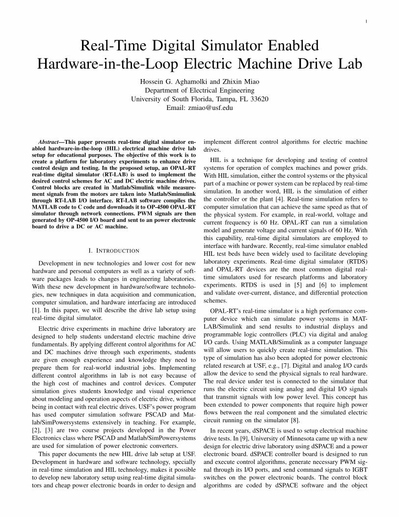
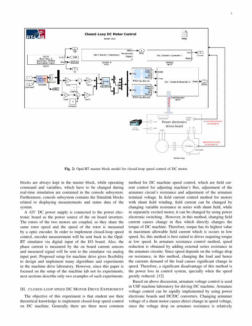
Fig. 2: Opal-RT master block model for closed-loop speed control of DC motor.
blocks are always kept in the master block, while operatingcommand and variables, which have to be changed duringreal-time simulation are contained in the console subsystem.Furthermore, console subsystem contains the Simulink blocksrelated to displaying measurements and status data of thesystem.
A 42V DC power supply is connected to the power elec-tronic board as the power source of the on board inverters.The rotors of the two motors are coupled, so they share thesame rotor speed and the speed of the rotor is measuredby a optic encoder. In order to implement closed-loop speedcontrol, encoder measurement will be sent back to the Opal-RT simulator via digital input of the I/O board. Also, thephase current is measured by the on board current sensorsand measured signal will be sent to the simulator via analoginput port. Proposed setup for machine drive gives flexibilityto design and implement many algorithms and experimentsin the machine drive laboratory. However, since this paper isfocused on the setup of the machine lab not its experiments,next sections describe only two examples of such experiments.
III. CLOSED-LOOP SPEED DC MOTOR DRIVE EXPERIMENT
The objective of this experiment is that student use theirtheoretical knowledge to implement closed-loop speed controlon DC machine. Generally there are three most common
method for DC machine speed control, which are field cur-rent control for adjusting machine’s flux, adjustment of thearmature circuit’s resistance and adjustment of the armatureterminal voltage. In field current control method for motorswith shunt field winding, field current can be changed bychanging variable resistance in series with shunt field, whilein separately excited motor, it can be changed by using powerelectronic switching . However, in this method, changing fieldcurrent causes change in flux which directly changes thetorque of DC machine. Therefore, torque has its highest valuein maximum allowable field current which is occurs in lowspeed. So, this method is best suited to drives requiring torqueat low speed. In armature resistance control method, speedreduction is obtained by adding external series resistance inthe armature circuite. Since speed depends on the voltage dropon resistance, in this method, changing the load and hencethe currents demand of the load causes significant change inspeed. Therefore, a significant disadvantage of this method isthe power loss in control system, specially when the speedgreatly reduced. [12]
Based on above discussion, armature voltage control is usedin USF machine laboratory for driving DC machine. Armaturevoltage control can be rapidly implemented by using powerelectronic boards and DC/DC converters. Changing armaturevoltage of a shunt motor causes direct change in speed voltage,since the voltage drop on armature resistance is relatively
4
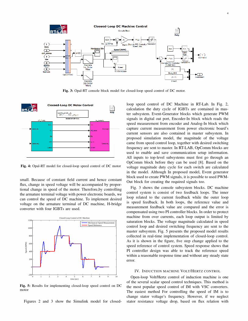
Fig. 3: Opal-RT console block model for closed-loop speed control of DC motor.
Fig. 4: Opal-RT model for closed-loop speed control of DC motor
small. Because of constant field current and hence constantflux, change in speed voltage will be accompanied by propor-tional change in speed of the motor. Therefore,by controllingthe armature terminal voltage with power electronic boards, wecan control the speed of DC machine. To implement desiredvoltage on the armature terminal of DC machine, H-bridgeconverter with four IGBTs are used.
0 1 2 3 4 5 6 7 8 9 10-200
0
200
400
600
800
1000
1200
time (sec)
Spee
d (R
PM)
Closed-Loop Control of DC Machine
Mechanical Speed MeasurementSpeed Reference
Fig. 5: Results for implementing closed-loop speed control on DCmotor
Figures 2 and 3 show the Simulink model for closed-
loop speed control of DC Machine in RT-Lab. In Fig. 2,calculation the duty cycle of IGBTs are contained in mas-ter subsystem. Event-Generator blocks which generate PWMsignals in digital out port, Encoder-In block which reads thespeed measurement from encoder and Analog-In block whichcapture current measurement from power electronic board’scurrent sensors are also contained in master subsystem. Inproposed simulation model, the magnitude of the voltagecame from speed control loop, together with desired switchingfrequency are sent to master. In RT-LAB, OpComm blocks areused to enable and save communication setup information.All inputs to top-level subsystems must first go through anOpComm block before they can be used [8]. Based on thevoltage magnitude duty cycle for each switch are calculatedin the model. Although In proposed model, Event generatorblock used to create PWM signals, it is possible to used PWM-Out block for creating the required signals too.
Fig. 3 shows the console subsystem blocks. DC machinecontrol system is consist of two feedback loops. The innerloop related to the current feedback while the outer loopis speed feedback. In both loops, the reference value andmeasurement feedback value are compared and the error iscompensated using two PI controller blocks. In order to protectmachine from over currents, each loop output is limited bysaturation blocks. The voltage magnitude calculated in speedcontrol loop and desired switching frequency are sent to themaster subsystem. Fig. 5 presents the proposed model resultscollected in real-time implementation of closed-loop control.As it is shown in the figure, five step change applied to thespeed reference of control system. Speed response shows thatPI controller design was able to track the reference speedwithin a reasonable response time and without any steady stateerror.
IV. INDUCTION MACHINE VOLT/HERTZ CONTROL
Open-loop Volt/Hertz control of induction machine is oneof the several scalar speed control techniques. This method isthe most popular speed control of IM with VSC converters.The easiest method For controlling the speed of IM is tochange stator voltage’s frequency. However, if we neglectstator resistance voltage drop, based on flux relation with
5
Power electronics
drives board
Current
Senser
B A
+
-
Machine Setup
GND
+42V
42V DC
Power supply
On board inverters
ENCODER
Induction
Machine
Speed Measurement(to Encoder-In)
Current Measurement(to Analog-In)
A B C
Indu
ction M
acchin
e PWM
Signals
DC
Motor
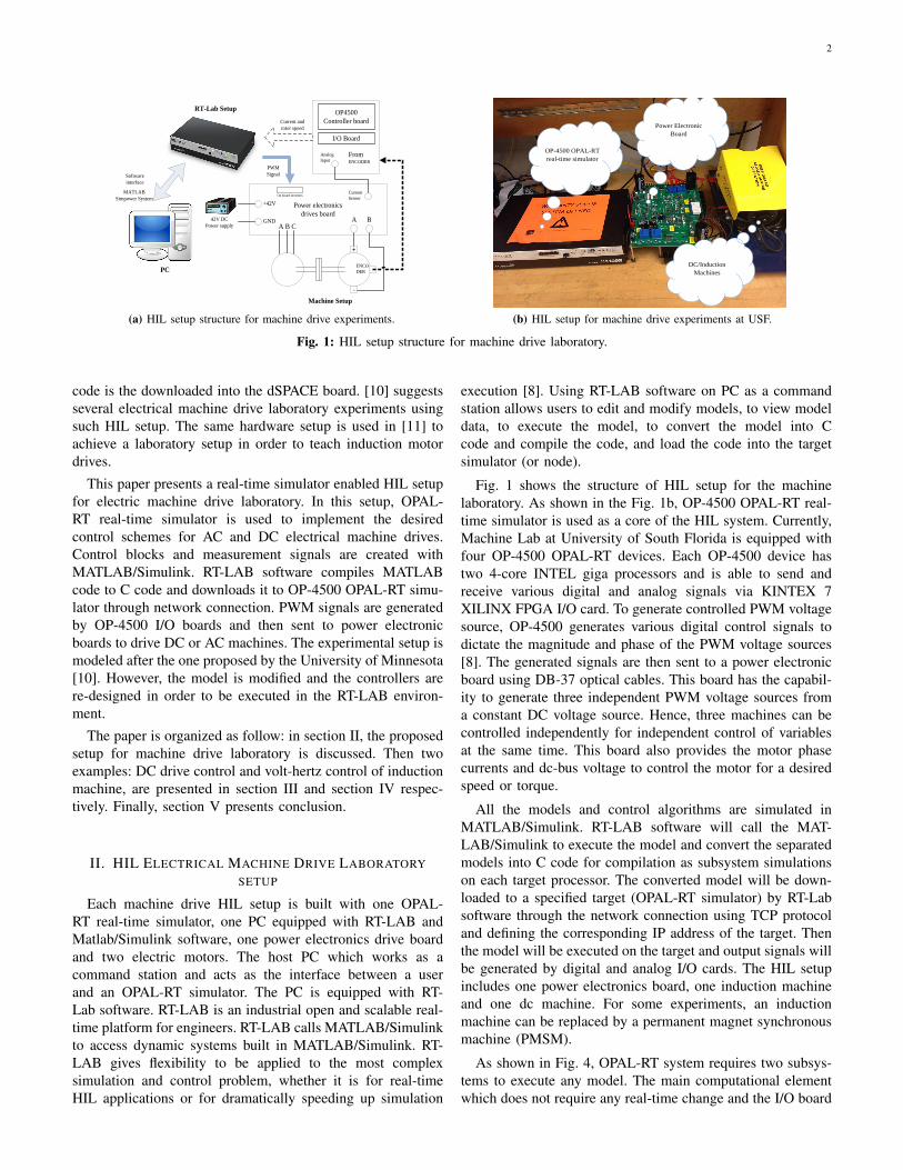
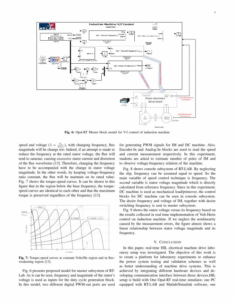
Fig. 6: Opal-RT Master block model for V-f control of induction machine
speed and voltage (λ = Vs
2πfs), with changing frequency, flux
magnitude will be change too. Indeed, if an attempt is made toreduce the frequency at the rated stator voltage, the flux willtend to saturate, causing excessive stator current and distortionof the flux waveforms [13]. Therefore, changing the frequencyhave to be accompanied with the change in stator voltagemagnitude. In the other words, by keeping voltage-frequencyratio constant, the flux will be maintain on its rated value.Fig. 7 shows the torque-speed curves. It can be shown in thisfigure that in the region below the base frequency, the torque-speed curves are identical to each other and that the maximumtorque is preserved regardless of the frequency [13].
Control Schemes in MATLAB/Simulink/dSPACE Environment for Educational Purpose
371
becomes negligible when the frequency grows. Finally, the f* command signal is integrated to generate the angle signal θ* which in combination with Us* produce the sinusoidal voltages.
0 0.5 1 1.50
0.2
0.4
0.6
0.8
1
[p.u.]bf f
[p.u
.]e
emTT
Without
boostU
With boostU
constantψ = constant sU ψ= →
emT
bf
Fig. 5. Torque-speed curves at constant Volts/Hz region and in flux-weakening region
Note that an improvement of the open-loop Volts/Hz control is the close-loop speed control by slip regulation (see, e.g., (Bose, 2002)).
IMVSISV PWM−
G
+boostU
+
*f
*
sU
*θ
f
sU
bf
cons
tant
ψ
=
ψ
Fig. 6. Open-loop Volts/Hz control of IM
4.2 Vector control
The objective of vector control of IM is to allow an IM to be controlled just like a separately excited dc motor drive (where the torque and the flux are controlled by two independent orthogonal variables: the armature and field currents, respectively). This is achieved by a
www.intechopen.com
Fig. 7: Torque-speed curves at constant Volts/Hz region and in flux-weakening region [13].
Fig. 6 presents proposed model for master subsystem of RT-Lab. As it can be seen, frequency and magnitude of the stator’svoltage is used as inputs for the duty cycle generation block.In this model, two different digital PWM-out ports are used
for generating PWM signals for IM and DC machine. Also,Encoder-In and Analog-In blocks are used to read the speedand current measurement respectively. In this experiment,students are asked to estimate number of poles of IM andto observe voltage-frequency relation of the machine.
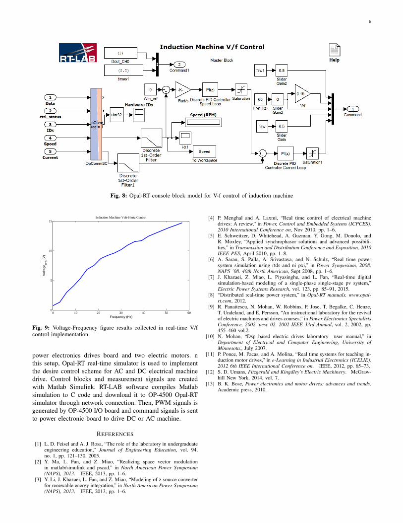
Fig. 8 shows console subsystem of RT-LAB. By neglectingthe slip, frequency can be assumed equal to speed. So themain variable of speed control technique is frequency. Thesecond variable is stator voltage magnitude which is directlycalculated from reference frequency. Since in this experiment,DC machine is used as mechanical load/primover, the controlblocks for DC machine can be seen in console subsystem.The desire frequency and voltage of IM, together with desireswitching frequency is sent to master subsystem.
Fig. 9 shows the stator voltage versus its frequency based onthe results collected in real-time implementation of Volt-Hertzcontrol on induction machine. If we neglect the nonlinearitycaused by the measurement errors, the figure almost shows alinear relationship between stator voltage magnitude and itsfrequency.
V. CONCLUSION
In this paper, real-time HIL electrical machine drive labo-ratory setup was investigated. The objective of this work isto create a platform for laboratory experiments to enhancethe power system testing and validation schemes as wellas better understanding of machine drive systems. This isachieved by integrating different hardware devices and de-veloping communication interface between those devices.HILsetup is build with One Opal-RT real-time simulator, one PCequipped with RT-LAB and Matlab/Simulink software, one
6
Fig. 8: Opal-RT console block model for V-f control of induction machine
0 10 20 30 40 50 600
5
10
15
Frequency (Hz)
Vol
tage
rms (V
)
Induction Machine Volt-Hertz Control
Fig. 9: Voltage-Frequency figure results collected in real-time V/fcontrol implementation
power electronics drives board and two electric motors. nthis setup, Opal-RT real-time simulator is used to implementthe desire control scheme for AC and DC electrical machinedrive. Control blocks and measurement signals are createdwith Matlab Simulink. RT-LAB software compiles Matlabsimulation to C code and download it to OP-4500 Opal-RTsimulator through network connection. Then, PWM signals isgenerated by OP-4500 I/O board and command signals is sentto power electronic board to drive DC or AC machine.
REFERENCES
[1] L. D. Feisel and A. J. Rosa, “The role of the laboratory in undergraduateengineering education,” Journal of Engineering Education, vol. 94,no. 1, pp. 121–130, 2005.
[2] Y. Ma, L. Fan, and Z. Miao, “Realizing space vector modulationin matlab/simulink and pscad,” in North American Power Symposium(NAPS), 2013. IEEE, 2013, pp. 1–6.
[3] Y. Li, J. Khazaei, L. Fan, and Z. Miao, “Modeling of z-source converterfor renewable energy integration,” in North American Power Symposium(NAPS), 2013. IEEE, 2013, pp. 1–6.
[4] P. Menghal and A. Laxmi, “Real time control of electrical machinedrives: A review,” in Power, Control and Embedded Systems (ICPCES),2010 International Conference on, Nov 2010, pp. 1–6.
[5] E. Schweitzer, D. Whitehead, A. Guzman, Y. Gong, M. Donolo, andR. Moxley, “Applied synchrophasor solutions and advanced possibili-ties,” in Transmission and Distribution Conference and Exposition, 2010IEEE PES, April 2010, pp. 1–8.
[6] A. Saran, S. Palla, A. Srivastava, and N. Schulz, “Real time powersystem simulation using rtds and ni pxi,” in Power Symposium, 2008.NAPS ’08. 40th North American, Sept 2008, pp. 1–6.
[7] J. Khazaei, Z. Miao, L. Piyasinghe, and L. Fan, “Real-time digitalsimulation-based modeling of a single-phase single-stage pv system,”Electric Power Systems Research, vol. 123, pp. 85–91, 2015.
[8] “Distributed real-time power system,” in Opal-RT manuals, www.opal-rt.com, 2012.
[9] R. Panaitescu, N. Mohan, W. Robbins, P. Jose, T. Begalke, C. Henze,T. Undeland, and E. Persson, “An instructional laboratory for the revivalof electric machines and drives courses,” in Power Electronics SpecialistsConference, 2002. pesc 02. 2002 IEEE 33rd Annual, vol. 2, 2002, pp.455–460 vol.2.
[10] N. Mohan, “Dsp based electric drives laboratory user manual,” inDepartment of Electrical and Computer Engineering, University ofMinnesota,, July 2007.
[11] P. Ponce, M. Pacas, and A. Molina, “Real time systems for teaching in-duction motor drives,” in e-Learning in Industrial Electronics (ICELIE),2012 6th IEEE International Conference on. IEEE, 2012, pp. 65–73.
[12] S. D. Umans, Fitzgerald and Kingdley’s Electric Machinery. McGraw-hill New York, 2014, vol. 7.
[13] B. K. Bose, Power electronics and motor drives: advances and trends.Academic press, 2010.