Embed Size (px)
Citation preview
CHANG, JEONG, HWANG: REAL-TIME HYBRID STEREO VISION SYSTEM 1
Real-time Hybrid Stereo Vision System forHD resolution disparity map
Jiho [email protected]
Jae-chan [email protected]
Dae-hwan [email protected]
Intelligent Cognitive TechnologyResearch DepartmentElectronics and TelecommunicationsResearch InstituteDaejeon, Republic of Korea
Abstract
Stereo vision systems have been researched for decades and constitute the traditionalmethod for extracting three-dimensional (3D) real-time depth information from imagesusing sensors. However, passive stereo vision systems show a significant error in process-ing untextured regions, which are frequent in indoor environments. Also, modificationsfor processing in real time make error by using approximate algorithms. In this paper, wepropose a hybrid stereo matching system that combines active and passive stereo vision.In order to implement it in a field-programmable gate array (FPGA) for real-time pro-cessing, we modify the existing stereo matching algorithm. Our system shows a signifi-cant improvement over current systems in processing untextured regions, and accuratelycalculates depth for a 1280 x 720-resolution image at 60fps in indoor environments.
1 IntroductionThe use of three-dimensional (3D) depth information has become a research area of signifi-cant interest in computer vision in recent years, and has numerous and varied applications infields such as human-computer interaction, robotics, surveillance, entertainment, etc. Sincethe release of Microsoft Kinect in particular, there has been rising interest in researching ap-plications based on 3D depth sensors. However, applications that use 3D depth informationhave trouble detecting thin and long objects, such as a human finger, at a distance of morethan three meters due to the limitations of 3D depth sensors and the corresponding algo-rithms. Stereo matching is a traditional method used to obtain 3D depth information and hasbeen studied for decades. However, it is still difficult to apply stereo matching algorithmsto practical devices due to real-time issues as well as the technique’s inability to adequatelyhandle untextured regions. Stereo matching can be classified into passive or active depend-ing on whether or not light, such as a laser or a structured light, is projected onto the object.As there is no light or pattern to be generated in a passive approach, results may be inac-curate if the camera captures a large untextured region [3]. Furthermore, when the imageis obtained in low illumination conditions, errors due to noise are possible. To reduce theseerrors and improve the accuracy of measured disparity, a global searching method has been
c© 2014. The copyright of this document resides with its authors.It may be distributed unchanged freely in print or electronic forms.

2 CHANG, JEONG, HWANG: REAL-TIME HYBRID STEREO VISION SYSTEM
proposed. However, it requires a large number of computations and shows a blurring effectfor thin objects [6].
A local stereo matching method using adaptive support-weight (ASW) cost aggregationwas introduced in 2005 by Yoon and Kweon [13]. It involves fewer computations than aglobal system and produces better results than other local methods. However, ASW re-quires a large support window to handle untextured regions, and thus needs considerablememory and processing resources to implement a field-programmable gate array (FPGA)or a General-Purpose computation on Graphics Processing Units (GPGPU) for real-timeprocessing [10]. For this reason, several researchers have used approximate algorithms toimplement in real-time, but such algorithms have not performed as well as the original ASWmethod [6] [5].
Recent studies have proposed cross-shaped filtering and information permeability fil-tering in place of ASW for real-time processing. Information permeability filtering [4] inparticular involves a much smaller number of calculations per pixel compared to ASW orapproximate algorithms, and its complexity is independent of support window size. Jeon etal. [8] have implemented information permeability filtering in GPUs, and Stefano [7] andAysu et al. [1] have implemented it in FPGAs.
In contrast, active stereo vision is a method for calculating the correspondence betweenthe projected patterns of stereo images using illuminators. Active stereo systems reduceerrors in untextured regions to a greater degree than passive stereo vision. Furthermore,because active stereo vision employs a light, it can reduce the effect of radiometric distortiongenerated by illumination variation. Active stereo is typically calculated by the method ofspace-time with images obtained by projecting different patterns to obtain a highly accuratedisparity. However, because of problems with using multiple frames, the implementation ofa real-time system with a high frame rate is not possible.
In this paper, we propose a hybrid stereo matching system to remedy the disadvantagesof active and passive stereo vision. Our system includes laser diodes to project a pattern ofrandom dots, and obtains pattern images to the left and the right in order to reduce error inuntextured regions commonly encountered in real indoor environments. We obtain imagesthrough infrared light-emitting diodes (IR LEDs) for cost aggregation by utilizing the supportweight. In this case, the cameras capture images without a pattern. We then generate the rawcost by locating the correspondence between the two pairs of images to the left and the rightacquired in this way. We then perform cost aggregation by combining the raw cost withsupport weights by using non-pattern images.
This paper is structured as follows. In Section 2, we explain the stereo matching algo-rithm. We then detail the configuration of our proposed system in Section 3 and presentits block diagram implemented using FPGA. Section 4 contains a performance comparisonbetween our proposed system and current stereo matching algorithms. We also compare theperformance of our system with that of Microsoft Kinect. We conclude and suggest avenuesfor future research in Section 5.
2 Stereo matching algorithmFollowing Scharstein and Szeliski’s taxonomy [11], we divide the stereo matching algorithminto four steps: matching cost computation, cost aggregation, disparity computation and dis-parity refinement. Our description of the algorithm takes into account issues in modificationsfor the hybrid system.
CHANG, JEONG, HWANG: REAL-TIME HYBRID STEREO VISION SYSTEM 3
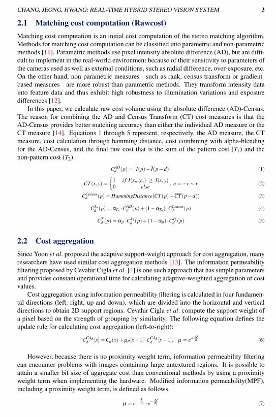
2.1 Matching cost computation (Rawcost)Matching cost computation is an initial cost computation of the stereo matching algorithm.Methods for matching cost computation can be classified into parametric and non-parametricmethods [11]. Parametric methods use pixel intensity absolute difference (AD), but are diffi-cult to implement in the real-world environment because of their sensitivity to parameters ofthe cameras used as well as external conditions, such as radial difference, over-exposure, etc.On the other hand, non-parametric measures - such as rank, census transform or gradient-based measures - are more robust than parametric methods. They transform intensity datainto feature data and thus exhibit high robustness to illumination variations and exposuredifferences [12].
In this paper, we calculate raw cost volume using the absolute difference (AD)-Census.The reason for combining the AD and Census Transform (CT) cost measures is that theAD-Census provides better matching accuracy than either the individual AD measure or theCT measure [14]. Equations 1 through 5 represent, respectively, the AD measure, the CTmeasure, cost calculation through hamming distance, cost combining with alpha-blendingfor the AD-Census, and the final raw cost that is the sum of the pattern cost (T1) and thenon-pattern cost (T2).
CADd (p) =
∣∣I(p)− I(p−d)∣∣ (1)
CT (x,y) ={
1 i f I(xn,yn) ≥ I(x,y)0 else , n =−r ∼ r (2)
CCensusd (p) = HammingDistance(CT (p)−CT (p−d)) (3)
CTnd (p) = αTn ·CAD
d (p)+(1−αTn ) ·CCensusd (p) (4)
CTd (p) = αp ·CT1
d (p)+(1−αp) ·CT2d (p) (5)
2.2 Cost aggregationSince Yoon et al. proposed the adaptive support-weight approach for cost aggregation, manyresearchers have used similar cost aggregation methods [13]. The information permeabilityfiltering proposed by Cevahir Cigla et al. [4] is one such approach that has simple parametersand provides constant operational time for calculating adaptive-weighted aggregation of costvalues.
Cost aggregation using information permeability filtering is calculated in four fundamen-tal directions (left, right, up and down), which are divided into the horizontal and verticaldirections to obtain 2D support regions. Cevahir Cigla et al. compute the support weight ofa pixel based on the strength of grouping by similarity. The following equation defines theupdate rule for calculating cost aggregation (left-to-right):
CCARd [x] =Cd(x)+µR[x−1] ·CCAR
d [x−1], µ = e−∆Iσ (6)
However, because there is no proximity weight term, information permeability filteringcan encounter problems with images containing large untextured regions. It is possible toattain a smaller bit size of aggregate cost than conventional methods by using a proximityweight term when implementing the hardware. Modified information permeability(MPF),including a proximity weight term, is defined as follows.
µ = e−1
σp · e−∆Iσs (7)

4 CHANG, JEONG, HWANG: REAL-TIME HYBRID STEREO VISION SYSTEM
CCARd [x] =Cd(x)+µH [x−1] ·CCAR
d [x−1] (8)
CCALd [x] =Cd(x)+µH [x+1] ·CCAR
d [x+1] (9)
CCAHd [x] =CCAL
d [x]+CCARd [x] (10)
CCATd [x,y] =CCAH
d (x,y)+µV [x,y−1] ·CCATd [x,y−1] (11)
CCABd [x,y] =CCAH
d (x,y)+µV [x,y+1] ·CCATd [x,y+1] (12)
2.3 Disparity computation
Disparity computation involves the calculation of the disparity that has been properly matchedwith the results of the calculation of raw cost. In the taxonomy of stereo matching, the clas-sification between global systems and local systems is made on account of a difference inthis step. Typically, a window with support weight uses the winner-take-all (WTA) method,which is used to select the disparity in minimum aggregated cost in the calculation of costvolume, as described in Section 2.2. WTA is simple and is represented by the followingequation:
d(p) = arg mind∈Sd
(CCAd (p)) (13)
Where Sd is the set of all possible disparities.
2.4 Disparity refinement
Disparity refinement reduces the error generated due to various problems during stereomatching. In this paper, we use left-right consistency (LRC) check and weighted medianfiltering (WMF) to eliminate error pixels from the results of disparity calculation. We alsouse sub-pixel estimation and weighted average filtering to obtain a more accurate disparitymeasure. A left-right consistency check is performed by comparing the left and right dis-parity maps, and we evaluate the performance of the refinement by a comparison with theground truth using only the LRC. A quantitative comparison between our proposed systemand Microsoft Kinect is difficult because the two have different fields of view (FOVs) andbecause the images in the latter are also post-processed. Thus, we only qualitatively compareour system with Microsoft Kinect.
3 Stereo vision system design
In this section, we describe our proposed system, which employs a time-multiplexed oper-ation associated projection of the laser diode (LD)/LED. The system is composed of twoparts, a stereo head and a stereo emulator. The stereo head includes a low-voltage differ-ential signaling (LVDS) module for data transmission, an LD/LED projection module andtwo complementary metal-oxide semiconductor (CMOS) sensors. The stereo emulator isbased on FPGA modules to obtain dense disparity maps from high-resolution stereo pairs.Our description of the algorithm takes into account issues in real-time implementation andmodifications for implementing it using FPGA.
CHANG, JEONG, HWANG: REAL-TIME HYBRID STEREO VISION SYSTEM 5
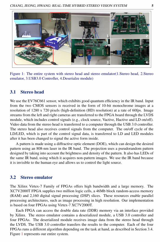
Figure 1: The entire system with stereo head and stereo emulator(1.Stereo head, 2.Stereoemulator, 3.USB3.0 Controller, 4.Deserialze module)
3.1 Stereo head
We use the EV76C661 sensor, which exhibits good quantum efficiency in the IR band. Inputfrom the two CMOS sensors is received in the form of 10-bit monochrome images at aresolution of 1280 x 720 pixels (high-definition (HD) resolution) at a rate of 60fps. Imagestreams from the left and right cameras are transferred to the FPGA board through the LVDSmodule, which includes control signals (e.g., clock source, Vactive, Hactive and LD on/off).Video data from the stereo head is transferred to a computer through the USB 3.0 controller.The stereo head also receives control signals from the computer. The on/off cycle of theLD/LED, which is part of the control signal data, is transferred to LD and LED modulesafter it has been changed to signal the active form inside.
A pattern is made using a diffractive optic element (DOE), which can design the desiredpattern using an 808-nm laser in the IR band. The projection uses a pseudorandom patterndesigned by taking into account the brightness and density of the pattern. It also has LEDs ofthe same IR band, using which it acquires non-pattern images. We use the IR band becauseit is invisible to the human eye and allows us to control the light source.
3.2 Stereo emulator
The Xilinx Virtex-7 Family of FPGAs offers high bandwidth and a large memory. TheXC7V2000T FPGA supplies two million logic cells, a 46Mb block random-access memory(RAM) and 2,160 digital signal processing (DSP) slices. These resources enable parallelprocessing architectures, such as image processing in high resolution. Our implementationis based on four FPGAs using Virtex-7 XC7V2000T.
Each FPGA can access the double data rate (DDR) memory via an interface providedby Xilinx. The stereo emulator contains a deserialized module, a USB 3.0 controller andfour FPGAs. The deserialized module receives image data from the stereo head throughthe LVDS. The USB 3.0 controller transfers the results to the computer. Each of the fourFPGAs runs a different algorithm depending on the task at hand, as described in Section 3.4.Figure 1 represents our entire system.

6 CHANG, JEONG, HWANG: REAL-TIME HYBRID STEREO VISION SYSTEM
3.3 Timing diagramThe hybrid system proposed in this paper captures a pair of pattern images (left and right)and an alternating pair of non-pattern images to evaluate disparity. Both pairs of imagesare used to calculate the raw cost, whereas the non-pattern images are also used to generatethe weight of the cost aggregation. The CMOS sensors are synchronized with the patternprojector in correct integration time, so that the images are obtained in operating time withthe LD (pattern) in one frame and with the LED (non-pattern) in the next frame.
Figure 2: The timing diagram for hybrid stereo matching
As shown in Figure 2, the disparity in the system is calculated using previous frames thatare stored and images being received at the time. The raw cost is calculated using T1 and T2and the cost aggregate is determined using images from T2. In this way, the disparity outputof our system has the same frame rate as the input image, and there is no frame dropping.
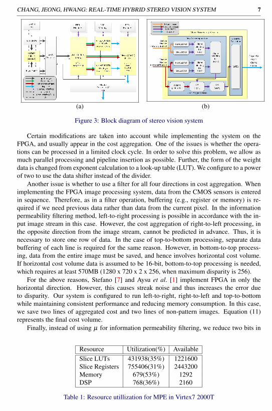
3.4 Implemeting stereo algorithmFigure 3 is a block diagram of the stereo vision system. The stereo matching algorithmconsists of four processing elements implemented in a single FPGA.
The pre-processing element (PrePE) is first composed through rectification and imagefiltering. Rectification is one of the most important parts of the stereo matching process be-cause of the epipolar constraint. In order to perform cost aggregation, the PrePE must rectifyan imput image under a one-pixel error in horizontal line. We implement rectification in thissystem based on the Caltech method. Using a square checkerboard, we extract the inter-nal and external parameters from the left/right cameras. These rectification parameters aretransferred to the host interface through the USB 3.0 controller. The PrePE then rectifies thepair of input images of each frame. Image filtering improves the results of cost aggregationand is applied, based on bilateral filtering, to the non-pattern images. The pattern selectordetermines the pattern image between the stored previous image and the current image byusing a control signal (pattern projector "on") received from the stereo head.
The Main Processing Element Left (MPE Left) generates a left-referenced disparity thatis implemented using the algorithm described in Section 2. In contrast, the Main ProcessingElement Right (MPE Right) generates a right-referenced disparity. Of course, the imple-mentation can be carried out, using the method referenced by Georgia et al. [9], by shiftingthe cost volume of the left-referenced disparity. However, this does not satisfy the timingrequirements of the FPGA.
CHANG, JEONG, HWANG: REAL-TIME HYBRID STEREO VISION SYSTEM 7
(a) (b)
Figure 3: Block diagram of stereo vision system
Certain modifications are taken into account while implementing the system on theFPGA, and usually appear in the cost aggregation. One of the issues is whether the opera-tions can be processed in a limited clock cycle. In order to solve this problem, we allow asmuch parallel processing and pipeline insertion as possible. Further, the form of the weightdata is changed from exponent calculation to a look-up table (LUT). We configure to a powerof two to use the data shifter instead of the divider.
Another issue is whether to use a filter for all four directions in cost aggregation. Whenimplementing the FPGA image processing system, data from the CMOS sensors is enteredin sequence. Therefore, as in a filter operation, buffering (e.g., register or memory) is re-quired if we need previous data rather than data from the current pixel. In the informationpermeability filtering method, left-to-right processing is possible in accordance with the in-put image stream in this case. However, the cost aggregation of right-to-left processing, inthe opposite direction from the image stream, cannot be predicted in advance. Thus, it isnecessary to store one row of data. In the case of top-to-bottom processing, separate databuffering of each line is required for the same reason. However, in bottom-to-top process-ing, data from the entire image must be saved, and hence involves horizontal cost volume.If horizontal cost volume data is assumed to be 16-bit, bottom-to-top processing is needed,which requires at least 570MB (1280 x 720 x 2 x 256, when maximum disparity is 256).
For the above reasons, Stefano [7] and Aysu et al. [1] implement FPGA in only thehorizontal direction. However, this causes streak noise and thus increases the error dueto disparity. Our system is configured to run left-to-right, right-to-left and top-to-bottomwhile maintaining consistent performance and reducing memory consumption. In this case,we save two lines of aggregated cost and two lines of non-pattern images. Equation (11)represents the final cost volume.
Finally, instead of using µ for information permeability filtering, we reduce two bits in
Resource Utilization(%) AvailableSlice LUTs 431938(35%) 1221600Slice Registers 755406(31%) 2443200Memory 679(53%) 1292DSP 768(36%) 2160
Table 1: Resource utillization for MPE in Virtex7 2000T

8 CHANG, JEONG, HWANG: REAL-TIME HYBRID STEREO VISION SYSTEM
the aggregated cost by adding a proximity term. Figure 3 shows a block diagram of the MPEfor implementing the proposed hybrid system. Table 1 shows the resource utilization inVirtex7 2000T. The parameters of the MPE are maximum census size = 11 x 11, maximumdisparity = 256, and image resolution = 1280 x 720.
The LRC eliminates the error due to disparity calculation results for occlusion regions.Sub-pixel estimation is implemented as a parabola fitting the costs and is calculated to divide4 bits more than 256 steps that are separated by a maximum disparity. So, steps of final dis-parity are 4096(256x16). The modification according to the post-processing described aboveimproves the sharpness of the disparity based on the original image and eliminates noise.However, it is difficult to quantitatively measure this performance improvement. Therefore,we propose qualitative results of post-processing for comparison of the shapes of the images.We present and evaluate quantitative measures only for LRC results.
4 Performance Evaluation
We evaluate performance in two ways: quantitative evaluation using the ground truth andqualitative evaluation using Microsoft Kinect.
4.1 Quantitative Evaluation
The ground truth is generally created using a space-time stereo in order to evaluate the per-formance of stereo vision [2]. We create the ground truth using thousands of images capturedby moving the pattern. Once we have captured two pairs of images - a pair of pattern imagesand a pair of non-pattern images - we fix the variable census window size (9 x 9), the valueof alpha for ADCT (0.4) and for hybrid (0.8). The performance of the system is then ana-lyzed by using different cost aggregation methods (information permeability, the proposedmethod, implementation to FPGA) and comparison between passive stereo matching andhybrid system using both of pattern images and non-pattern images.
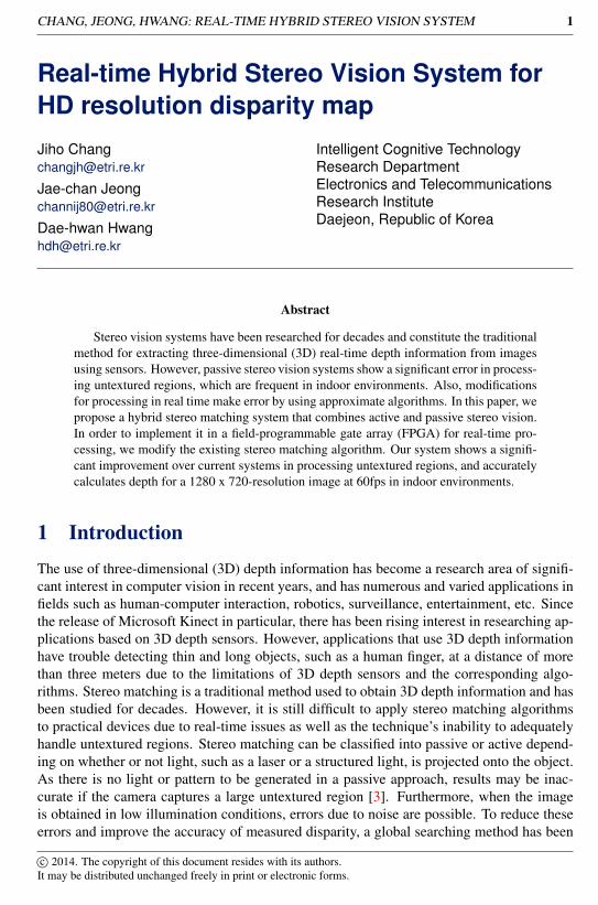
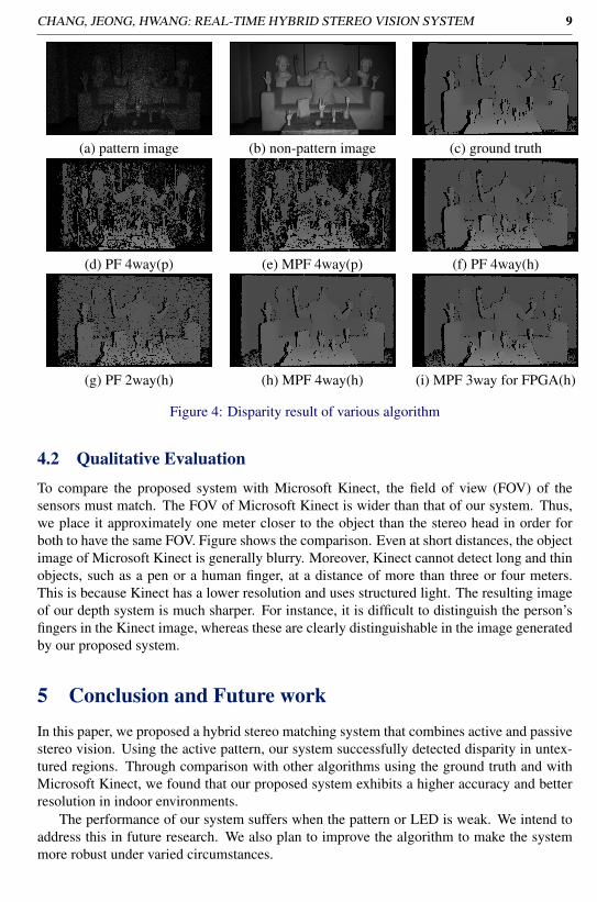
Table 2 and Figure 4 show the results for each algorithm. We see that our proposed stereosystem is better than the original passive stereo algorithm as well as variations of it to addressuntextured regions. Further, when applying the hybrid approach, the MPF has lesser streaknoises than the conventional real-time two-way permeability filtering (PF). We also see thatthe three-way method for FPGA performs just as well as the four-way method, except forthe fact that the sharpness of the object is different for the two methods.
Algorithm error(%)Not using pattern image PF 4way 61.67%
(Passive stereo matching) MPF 4way 54.54%
Using pattern image (Hybrid system)
PF 4way 5.14%PF 2way(Horizontal) 11.39%
MPF 4way 3.69%MPF 3way 4.78%
MPF 3way for FPGA 3.80%
Table 2: Error pixel rate on non-occlusion regions.
CHANG, JEONG, HWANG: REAL-TIME HYBRID STEREO VISION SYSTEM 9
(a) pattern image (b) non-pattern image (c) ground truth
(d) PF 4way(p) (e) MPF 4way(p) (f) PF 4way(h)
(g) PF 2way(h) (h) MPF 4way(h) (i) MPF 3way for FPGA(h)
Figure 4: Disparity result of various algorithm
4.2 Qualitative Evaluation
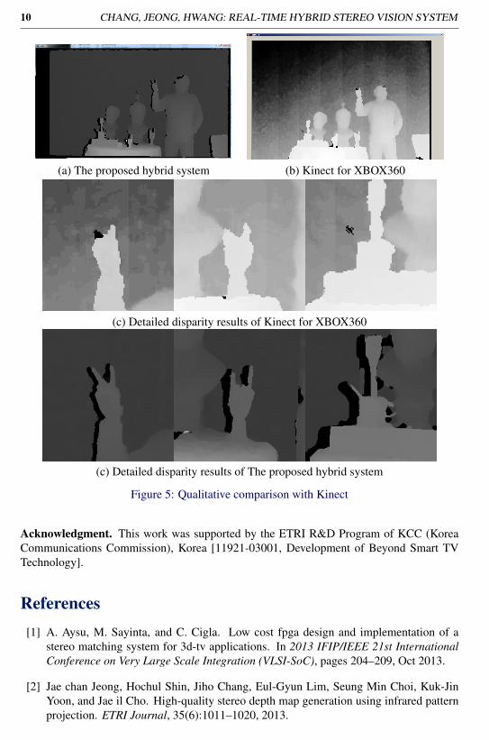
To compare the proposed system with Microsoft Kinect, the field of view (FOV) of thesensors must match. The FOV of Microsoft Kinect is wider than that of our system. Thus,we place it approximately one meter closer to the object than the stereo head in order forboth to have the same FOV. Figure shows the comparison. Even at short distances, the objectimage of Microsoft Kinect is generally blurry. Moreover, Kinect cannot detect long and thinobjects, such as a pen or a human finger, at a distance of more than three or four meters.This is because Kinect has a lower resolution and uses structured light. The resulting imageof our depth system is much sharper. For instance, it is difficult to distinguish the person’sfingers in the Kinect image, whereas these are clearly distinguishable in the image generatedby our proposed system.
5 Conclusion and Future workIn this paper, we proposed a hybrid stereo matching system that combines active and passivestereo vision. Using the active pattern, our system successfully detected disparity in untex-tured regions. Through comparison with other algorithms using the ground truth and withMicrosoft Kinect, we found that our proposed system exhibits a higher accuracy and betterresolution in indoor environments.
The performance of our system suffers when the pattern or LED is weak. We intend toaddress this in future research. We also plan to improve the algorithm to make the systemmore robust under varied circumstances.
10 CHANG, JEONG, HWANG: REAL-TIME HYBRID STEREO VISION SYSTEM
(a) The proposed hybrid system (b) Kinect for XBOX360
(c) Detailed disparity results of Kinect for XBOX360
(c) Detailed disparity results of The proposed hybrid system
Figure 5: Qualitative comparison with Kinect
Acknowledgment. This work was supported by the ETRI R&D Program of KCC (KoreaCommunications Commission), Korea [11921-03001, Development of Beyond Smart TVTechnology].
References[1] A. Aysu, M. Sayinta, and C. Cigla. Low cost fpga design and implementation of a
stereo matching system for 3d-tv applications. In 2013 IFIP/IEEE 21st InternationalConference on Very Large Scale Integration (VLSI-SoC), pages 204–209, Oct 2013.
[2] Jae chan Jeong, Hochul Shin, Jiho Chang, Eul-Gyun Lim, Seung Min Choi, Kuk-JinYoon, and Jae il Cho. High-quality stereo depth map generation using infrared patternprojection. ETRI Journal, 35(6):1011–1020, 2013.

CHANG, JEONG, HWANG: REAL-TIME HYBRID STEREO VISION SYSTEM 11
[3] Chichyang Chen and Y.F. Zheng. Passive and active stereo vision for smooth surfacedetection of deformed plates. IEEE Transactions on Industrial Electronics, 42(3):300–306, Jun 1995.
[4] C. Cigla and A.A. Alatan. Efficient edge-preserving stereo matching. Computer VisionWorkshops (ICCV Workshops), 2011 IEEE International Conference on, pages 696–699, 2011.
[5] Jingting Ding, Jilin Liu, Wenhui Zhou, Haibin Yu, Yanchang Wang, and XiaojinGong. Real-time stereo vision system using adaptive weight cost aggregation approach.EURASIP Journal on Image and Video Processing, 2011(1):1–19, 2011.
[6] A. Hosni, M. Bleyer, and M. Gelautz. Secrets of adaptive support weight techniques forlocal stereo matching. Computer Vision and Image Understanding, 117(6):620–632,2013.
[7] S. Mattoccia. Stereo vision algorithms for fpgas. In 2013 IEEE Conference on Com-puter Vision and Pattern Recognition Workshops (CVPRW), pages 636–641, June 2013.
[8] Cuong Cao Pham and Jae Wook Jeon. Domain transformation-based efficient costaggregation for local stereo matching. IEEE Transactions on Circuits and Systems forVideo Technology, 23(7):1119–1130, July 2013.
[9] G. Rematska, K. Papadimitriou, and A. Dollas. A low cost embedded real time 3dstereo matching system for surveillance applications. In Bioinformatics and Bioengi-neering (BIBE), 2013 IEEE 13th International Conference on, pages 1–6, Nov 2013.
[10] Christian Richardt, Douglas Orr, Ian Davies, Antonio Criminisi, and NeilA. Dodgson.Real-time spatiotemporal stereo matching using the dual-cross-bilateral grid. In Com-puter Vision âAS ECCV 2010, volume 6313 of Lecture Notes in Computer Science,pages 510–523. 2010.
[11] D. Scharstein, R. Szeliski, and R. Zabih. A taxonomy and evaluation of dense two-frame stereo correspondence algorithms. In Stereo and Multi-Baseline Vision, 2001.(SMBV 2001). Proceedings. IEEE Workshop on, pages 131–140, 2001.
[12] Xun Sun, Xing Mei, shaohui Jiao, Mingcai Zhou, and Haitao Wang. Stereo matchingwith reliable disparity propagation. In 2011 International Conference on 3D Imaging,Modeling, Processing, Visualization and Transmission (3DIMPVT), pages 132–139,May 2011.
[13] Kuk-Jin Yoon and In-So Kweon. Adaptive support-weight approach for correspon-dence search. IEEE Transactions on Pattern Analysis and Machine Intelligence, 28(4):650–656, April 2006.
[14] Ramin Zabih and John Woodfill. Non-parametric local transforms for computing visualcorrespondence. In Computer Vision - ECCV ’94, volume 801 of Lecture Notes inComputer Science, pages 151–158. 1994.