Embed Size (px)
Citation preview
Prof.Darshan S.Patel
M.Tech (Power Electronics & Drives)
Assistant Professor,Department of Electrical Engineering
Sankalchand Patel College of Engineerig-VisnagarE-mail:[email protected]
URL:www.darshanspatel.weebly.com
Real Time Implementation
of
Power Electronics System

What is power electronics?
Power Electronics: is the electronics applied to
conversion and control of electric power.
milli watts
giga watts
mega watts

Power
Processor
Controller
Load
measurement
reference
POWER
INPUTPOWER
OUTPUT
vi , ii vo , io
Source

Technology Associated with Efficient Conversion, Control and
Conditioning of electric power/energy using semiconductor
devices from any available electric input form to any
desirable output power form.
Input Electric Power :AC/DC in the form of (Voltage/Current)
Output Electric Power :AC/DC in the form of (Voltage/Current)
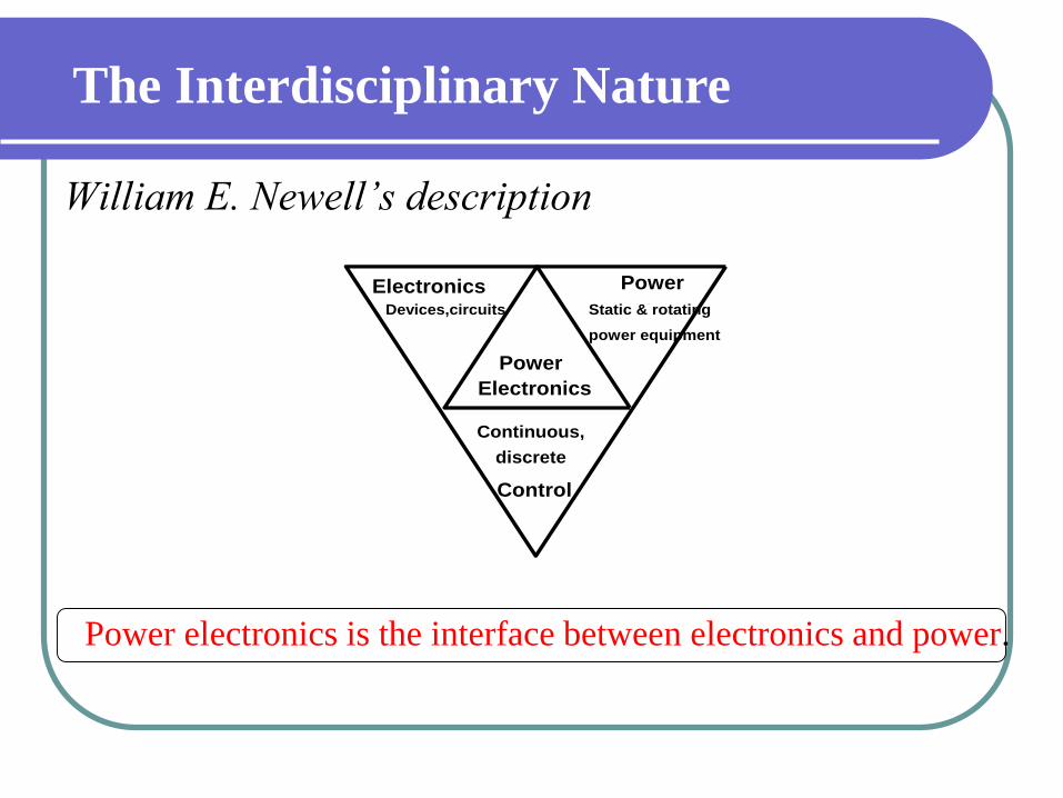
William E. Newell’s description
Power electronics is the interface between electronics and power.
Power
Electronics
学
Electronics
Power
学
Control
Continuous,
discrete
连续、离
散
Static & rotating
power equipment
Devices,circuits
The Interdisciplinary Nature
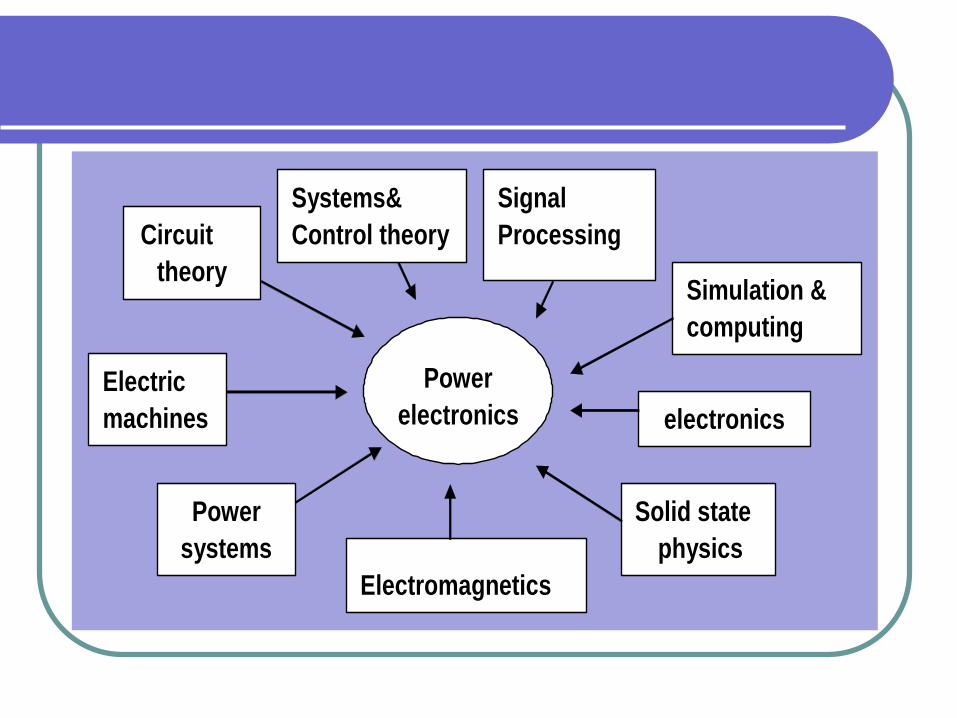
Power
electronics
electroni
cs
electr
Electric
machines
Circuit Ct
theory
Systems&
Control theory
Control
theory
Signal
Processing
Simulation &
computing
electronics
Solid state
physics
Electromagnetics
Power
systems

The Lohner-Porsche Mixte Hybrid was the first hybrid
vehicle developed by Ferdinand Porsche. (1990’s)


Battery operated 2 Wheelers

Power semiconductor devices
(Power switches)
Power switches: work-horses of PE
systems.
Operates in two states:
Fully on. i.e. switch closed.
Conducting state
Fully off , i.e. switch opened.
Blocking state
Power switch never operates in
linear mode.
POWER SWITCH
SWITCH ON (fully closed)
Vin
Vswitch
= 0
I
SWITCH OFF (fully opened)
Vin
Vswitch
= Vin
I=0


12
• Can be categorised into three
groups:
– Uncontrolled: Diode
– Semi-controlled: Thyristor
(SCR).
– Fully controlled:
– Power transistors:
e.g. BJT, MOSFET, IGBT,
GTO, IGCT

13

+
VCE
_
IC
C (collector)
G (gate)
E (emitter)
+
VGE _
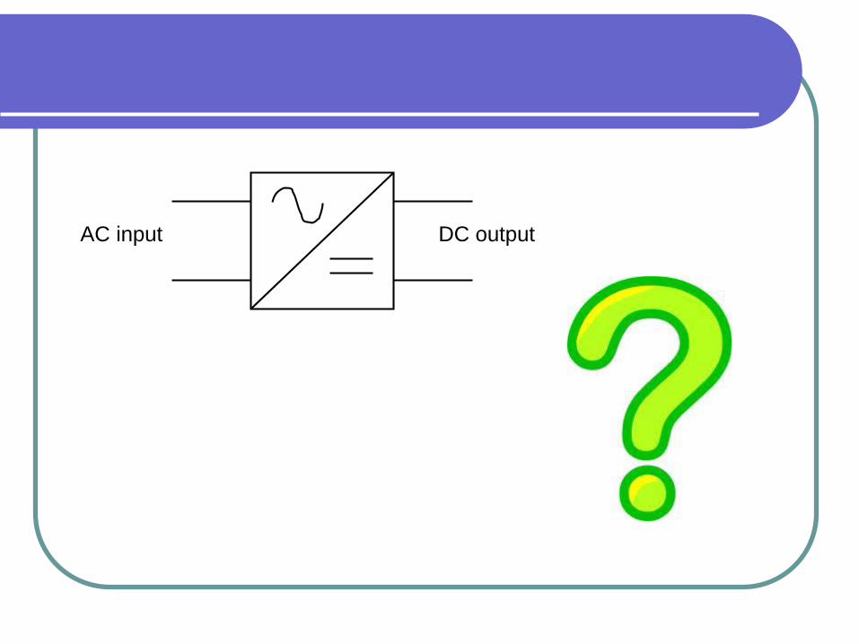
AC input DC output

DC input DC output

DC input AC output

AC
VoltageController
V0(RMS)
fS
Variable AC
RMS O/P Voltage
AC
Input
Voltage
fs
Vs
fs

Power Conversion Concept
Supply from 50Hz, 240V
RMS (340V peak). Customer
need DC voltage for welding
purpose, say.
sine-wave supply gives zero
DC component!
We can use simple half-wave
rectifier. A fixed DC voltage is
now obtained. This is a
simple PE system.
tim
e
Vs (Volt)
Vo
tim
e
Vdc

+
Vs
_

21
How if customer wants variable DC voltage?
More complex circuit using SCR is required.
wt
vo
a
ig
wt
wt
vs
+
vo
_
+
vs
_
ig
ia


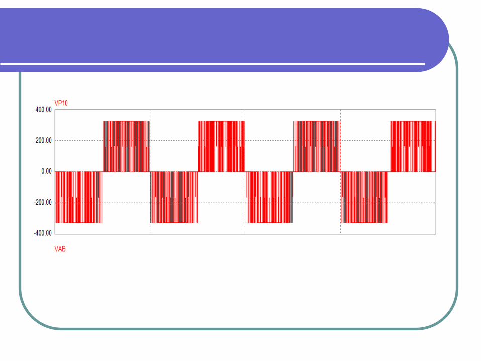
Sine PWM.


AC-AC Converter
AC Voltage Controller

Simulink Diagram
Continuous
pow ergui
v+-
Voltage Measurement1
v+-
Voltage Measurement
+
Series RLC Branch
Scope
Pulse
Generator1
Pulse
Generator
gm
ak
Detailed Thyristor1
g m
a k
Detailed Thyristor
DC Voltage Source
i+
-
Current Measurement
AC Voltage Source


What about Real Time ???
Simulation is for the verification only
Hardware Implementation is must for the
Power conversion.
HOW????? Microcontrollers
DSPs
FPGA
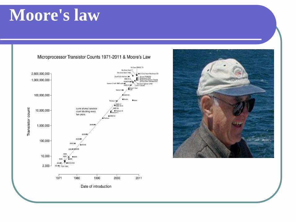
Moore's law

Early day (1970’s/80’s)
Intel 8048
Intel 8051
Zilog Z8
Motorola 68HC05
Popular Microcontrollers
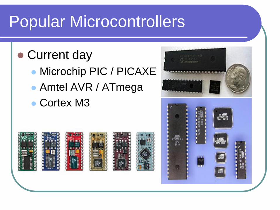
Popular Microcontrollers
Current day
Microchip PIC / PICAXE
Amtel AVR / ATmega
Cortex M3

Hardware Implementation
of
Full Bridge Inverter using 89C51

Block Diagram
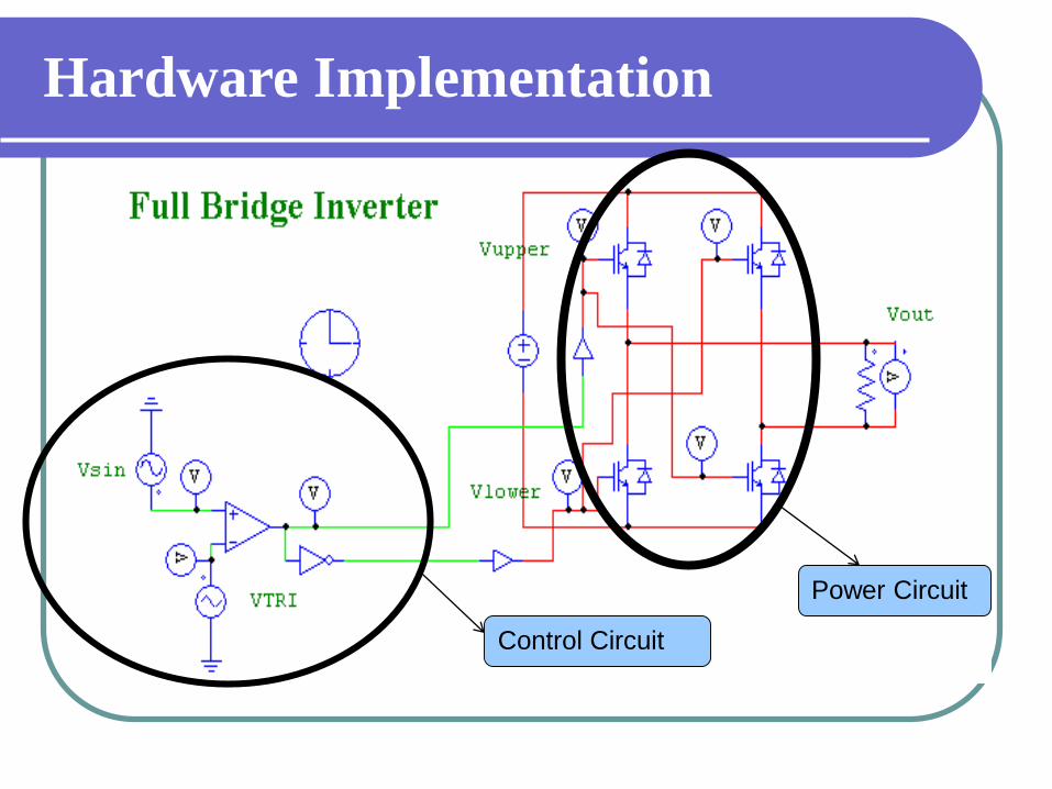
Power Circuit
Control Circuit
Hardware Implementation

Testing of controller card in Proteus software

Microcontroller Card


Simulation/Hardware Results
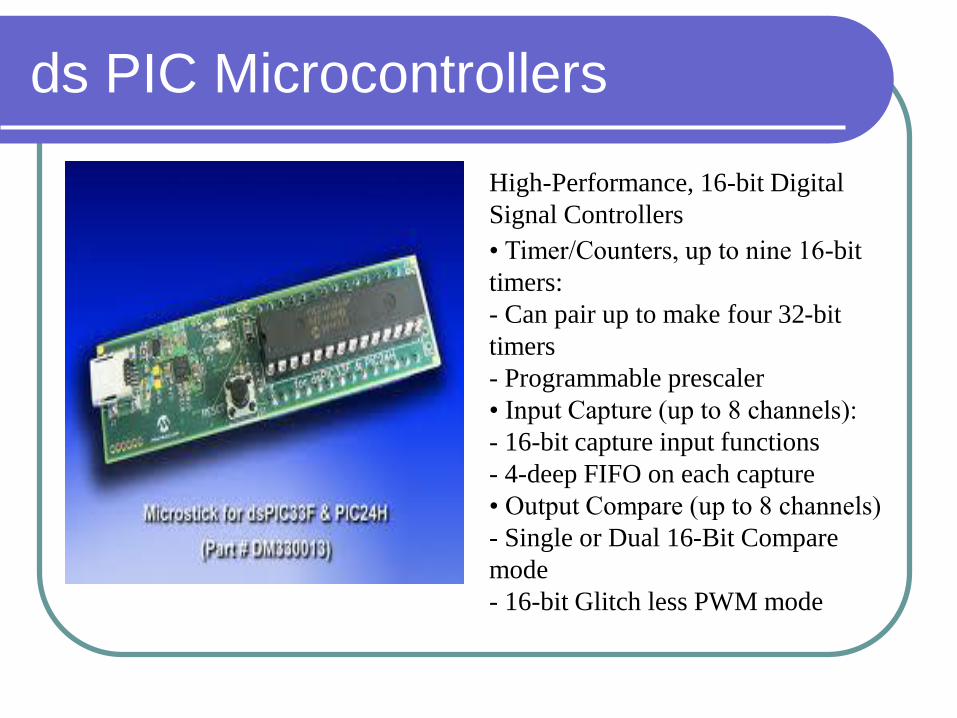
ds PIC Microcontrollers
High-Performance, 16-bit Digital
Signal Controllers
• Timer/Counters, up to nine 16-bit
timers:
- Can pair up to make four 32-bit
timers
- Programmable prescaler
• Input Capture (up to 8 channels):
- 16-bit capture input functions
- 4-deep FIFO on each capture
• Output Compare (up to 8 channels)
- Single or Dual 16-Bit Compare
mode
- 16-bit Glitch less PWM mode

Ardunio
A free development system based on Atmel AVR 8 bit microcontrollers.

Digital IO (LEDs, switches)
Analog IO (resistive sensor data)
Serial Connection (Sensors, GPS etc..)
Program from your computer
Your limit is only your creativity!
What do these do?

Arduino I/O Boards
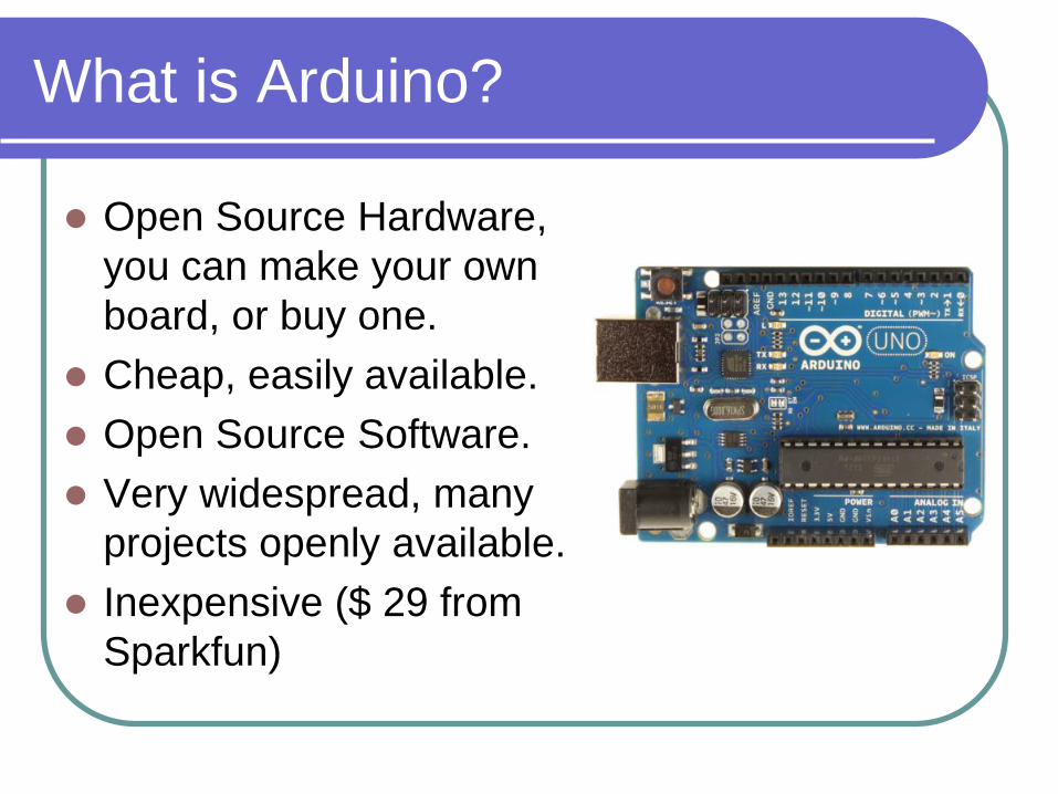
What is Arduino?
Open Source Hardware,
you can make your own
board, or buy one.
Cheap, easily available.
Open Source Software.
Very widespread, many
projects openly available.
Inexpensive ($ 29 from
Sparkfun)

Arduino (ATmega based)
The 555 of the 21st century
Open Source Hardware
Open architecture for expansion
USB, Ethernet, wireless, motor, LCD
Open Source Software Development Tools
Integrated Development Environment
Rich library sets for supporting peripherals
I/O


Arduino Instruction Set

Arduino Board Overview
Arduino Language
C like syntax, but simplified
Abstracts the pin naming to numbers
Trades efficience for ease of use
Easy to learn, yet powerful
Lots of example code
Easy to reuse C-code from other projects
Libraries can be written in C++
Lots of libraries available

Programming the Arduino

Sample code for LED
// Pin 13 has an LED connected on most Arduino boards.
// give it a name:
int led = 13;
// the setup routine runs once when you press reset:
void setup() {
// initialize the digital pin as an output.
pinMode(led, OUTPUT);
}
// the loop routine runs over and over again forever:
void loop()
{
digitalWrite(led, HIGH); // turn the LED on (HIGH is the voltage level)
delay(1000); // wait for a second
digitalWrite(led, LOW); // turn the LED off by making the voltage LOW
delay(1000); // wait for a second
}

A call to analog Write()
is on a scale of 0 - 255,
such that analog.
Write (255) requests a
100% duty cycle (always
on).
Analog Write(127) is a
50% duty cycle (on half
the time) for example.

dSPACE Work Station

dSPACE DS1103 system consisting of:
DS1103 Board.
Expansion Box.
CLP1103 PPC Connector and LED Panel.
Control Desk Version 3.2.2/Other dSPACE
provided Software Applications.
PC dedicated to the workstation containing other
software applications required (Matlab/Simulink
Version R2008a and libraries).

DS1103 Workstation

PWM Output
pulses_ms_to_Hz
1000
Terminator 1
Terminator
RTI Data
RPM_to_Hz
50 .2996
RPM _in
0
Kz
.010417
K
5871 .7
Hz_to_pulses_ms
.001
Hz_to_RPM
.019881
Hz_DutyCycle
.00003
Ground
Gc
z +1.932751 z+0.9327512
z -1.39989 z+0.3998942
DS1103SL_DSP_PWM
PWM Channel 1
PWM Channel 2
PWM Channel 3
PWM Channel 4
DS1103 ENC_SETUP
ENCODER
MASTER SETUP
DS1103 ENC_POS_C1
Enc position
Enc delta position
0_to_1
DutyCycle
pulses_ms_out
RPM_in pulses_ms_inHz
Hz RPM_out
Kz_out TF_outGain_outSum Duty
PWM Output
Hardware Implementation of Three Level
CHB inverter using DSP

62
Simulation of Three Phase Three Level CHB Inverter
Cascaded H bridge Inverter
PWM Controller
Load

63
64
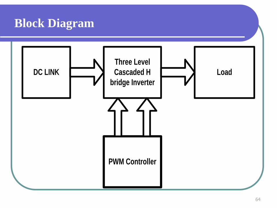
Block Diagram
DC LINK
Three Level
Cascaded H
bridge Inverter
Load
PWM Controller

65
Arrangement of DC Link
Given CHB Topology of Multilevel inverter needed Three
separate DC Link for three module of H Bridge.
For that Three transformer for isolation and three rectifier is
used for generate the DC Link Voltage.
66
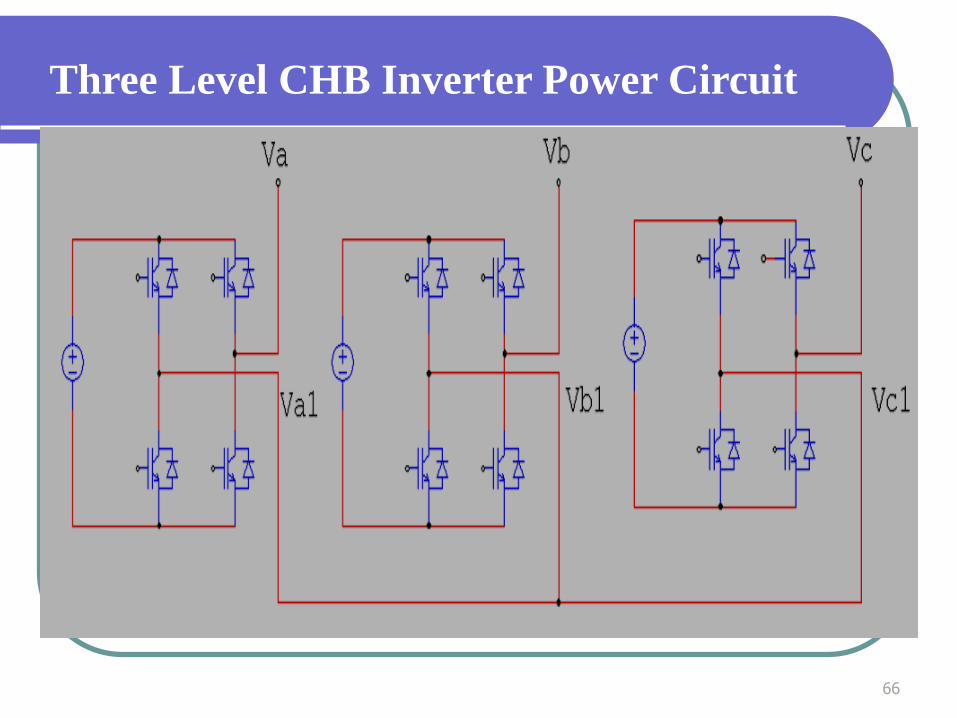
Three Level CHB Inverter Power Circuit

67
Three Level CHB Inverter Power Circuit
For the Proposed Prototype Three Phase Three Level
Inverter 12 IGBTs Used of Infineon make IKW40T120.
Two carriers and one Modulating signal needed for
generating the pulses for 12 IGBTs.
Separate Three DC Links needed for the proposed
prototype.

68
Block Diagram of the Control Circuit
From The TMS320F24PQ DSP control card 12 Signals
Generated which distribute into the four of top and bottom signals
for each module Leg.
Into the FRC connector card six 14 Pins connectors are used
from which each connector gives the top bottom pulses to the
each leg.

69

70
TMS320F240PQ Control Card
Signals From The DSP to Driver
card Through FRC
DSP Signal to GATE
DRIVER Through FRC

71
FRC Connector


73

74
75
Power Testing
The prototype testing of the three-level inverter has been
carried out and the results have been verified. Various quantities
and waveforms have been observed and recorded for the further
analysis.
The 3-level Phase Shifted SPWM scheme is used for the PWM
signal generation.
During the Power Testing of the Inverter line to neutral and
line to line voltages waveform observed and satisfactory results
obtained.

76
Waveforms for Line to Neutral Voltages
Van
Vcn

Popular Digital Controllers
Texas Instruments(TI) Microcontrollers And Digital Signal
Processors MSP430
TMS320F2407
TMS3202812–Series
Piccolo, Delfino, Concerto etc.
Micro-Chip DsPIC Micro-controllers
DSPACE–Simulink Based Controller RT-1104
RT-1103
RT–1105
OPAL-RT
National Instruments(NI) Lab-View
FPGA Based Digital Controllers
Xilinx, Altera
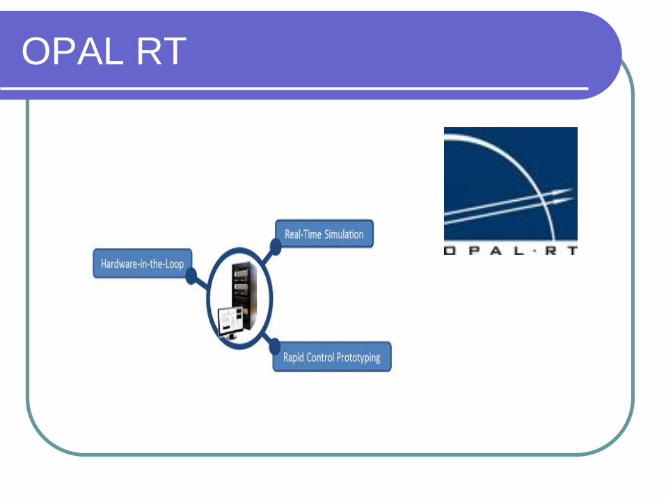
OPAL RT

Large Scale Power Grid Simulation
Smart Grid and Renewable Energy
High Voltage Power Electronics
Plugin Hybrid and Drives
Control and Data Acquisition

Virtual Instrumentation With Lab VIEW


Some IDEs


U can Down load this Presentation
www.darshanspatel.weebly.com
Thank U