Embed Size (px)
Citation preview
Abstract -- This paper investigates the development and
implementation of a real-time thermal ageing model for
polymer-based electrical wire insulation using the classical
Arrhenius relationship for chemical reaction rates. The paper
presents the theoretical development and implementation of
the method for predicting the insulation lifetime based on real-
time temperature measurements using fibre-optic sensors
embedded inside copper-wound coils. The performance of the
presented lifetime model in delivering consistent results for
winding insulation lifetime predictions is then assessed and
validated using real-time steady-state and transient thermal
experiments on a wound test coil mounted into a purpose built
motorette test rig.
Index Terms— Coil, fibre-optic, insulation lifetime,
model, motorette, real-time, sensor, steady-state, transient
and thermal ageing.
I. INTRODUCTION
LECTRICAL machines are essentially wound components for modern industrial systems. During
operation, the insulation materials in electrical machines are exposed to thermal stresses. These thermal stresses initiate progressive degradation of the insulation materials, which lead to the deterioration of the insulation characteristics and consequently to insulation breakdown [1]. Therefore, knowledge relating to the condition of the insulation systems and an estimation of the remaining life has become an important concern to manufacturers and users of electrical systems [2]. Real-Time lifetime prediction of insulation materials is of interest in this work. Severe winding insulation breakdown due to thermal stresses have been reported as contributing to as much as 30-40% of all stator winding failures in conventional induction machines [3]. It was also reported in [4-6] that thermal ageing is the dominant ageing factor and can contribute up to ≈31% of the deterioration of the insulation materials.
The lifespan of the insulation is usually predicted using accelerated ageing tests. An accelerated ageing test is used in
This work was supported by the EPSRC National Centre for Power Electronics UK.
K. Tshiloz is with the Power and Energy Division Group, The University of Manchester, Manchester M13 9PL, UK. (e-mail: [email protected]).
A. C. Smith is with the Power and Energy Division Group, The University of Manchester, Manchester M13 9PL, UK. (e-mail: [email protected]).
A. Mohammed is with the Power and Energy Division Group, The University of Manchester, Manchester M13 9PL, UK. (e-mail: [email protected]).
S. Djurović is with the Power and Energy Division Group, The University of Manchester, Manchester M13 9PL, UK. (e-mail: [email protected]).
T. Feehally is with the Power and Energy Division Group, The University of Manchester, Manchester M13 9PL, UK. (e-mail: [email protected]).
the effort to obtain failure statistics in shorter timescales. In [2, 7], the lifetime of the insulation material was estimated using an electro-thermal ageing model that takes into account the combined electrical and thermal stresses in the lifetime prediction. Real-time insulation lifetime predictions during steady-state and transient operating conditions of wound components have received less attention in the available literature.
The thermal ageing model based on the classical Arrhenius relationship can be adapted for real-time steady-state and transient thermal ageing predictions of the insulation materials for wound components. The key input to the insulation lifetime model is the measured temperature distribution around the winding insulation.
Winding temperatures are conventionally sensed using thermocouples or resistance temperature detectors embedded on the exposed external surfaces of the electrical machine and/or windings [8]. These techniques commonly provide single-point temperature measurements that are often unreliable [8]. Moreover, these sensors come with significant challenges imposed by the location of the sensors close to or within the stator windings for example due to use of electrically conductive materials in the sensor packages as well as susceptibility to electromagnetic interference [8]. The key objective in this work is to access the capability of predicting real-time remaining life of wound components insulation materials using Fibre Bragg Grating (FBG) sensors embedded directly into the stator coils during fabrication. The FBG sensors are fibre-optic sensors that have been used in other applications, ranging from frame vibration sensing of the stator core and coil surface thermal monitoring [9-12]. The FBG sensors are small and can be laid into the middle of the coils during the wind process and can provide real-time temperature information at several measurement points around the coil length in a single fibre. The FBG sensor has the inherent advantage of electromagnetic interference immunity making it a strong candidate for enabling reliable real-time temperature measurement in wound components. The performance of the insulation model in delivering reliable real-time lifetime predictions is assessed by direct comparison with the standard lifetime of conventional class H winding insulation. The thermal ageing algorithm is implemented on a SmartScan 04 Dynamic FBG Interrogator real-time platform. The model performance is evaluated on a purpose built motorette test rig. The presented ageing model is shown to have good potential for providing remaining real-time lifetimes of wound components under varying temperature which is representative of a motor under varying load conditions.
II. EXPERIMENTAL SET-UP
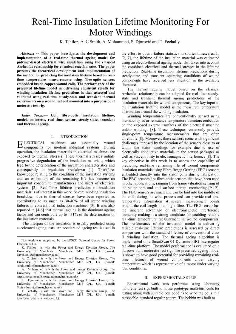
Experimental work was performed using laboratory
motorette test rigs built to house prototype multi-turn coils for
testing along with suitable coil bobbins to wind the coils in a
reasonable standard regular pattern. The bobbin was built to
Real-Time Insulation Lifetime Monitoring For Motor Windings
K. Tshiloz, A. C Smith, A. Mohammed, S. Djurović and T. Feehally
E
4 temperature sensing points
Test coils and temperature sensing
a b Fig.1: a) Built coil bobbin, b) Proposed positions for FBG temperature sensors embedded in middle of the coil
wind random coils using an existing coil winding rig
available in the laboratory. The manufactured bobbin can be
easily dismantled to allow the removal of the test coil without
damaging the insulation. The winding speed was kept low in
order to increase the wire tension and produce coils with a
reasonable packing factor of ≈40% [13]. The dimensions of
the motorette are given in IEEE standard 177 [14].
The distance between the two parallel sides at the middle
of the coil is ≈51mm. The number of turns of the coil was 40
turns made from 0.9mm diameter standard Class H enamel
copper wire and the temperatures were measured using a
single fibre-bragg sensor embedded into the test coil as
shown in Fig.1a. The temperature signals were recorded and
processed using a SmartScan 04 Dynamic FBG Interrogator
platform [15]. The SmartScan 04 can dynamically measure
the wavelength in nanometres of the fibre-optic sensors in the
fibre caused by the temperature variations. The measured
wavelengths are then processed using a LabVIEW code to
obtain the real-time temperatures. The real-time temperatures
are then fed into the thermal ageing model described in
section IV to obtain real-time lifetime predictions of the
insulation materials. The SmartScan 04 has a scanning
frequency of 2.5 kHz with a wavelength resolution of less
than 1 picometre [15]. A programmable Sorensen SGI
100/50 DC power supply [16] was used to energise the test
coil with a DC current in order to investigate different
dynamic thermal ageing tests.
The main advantage of this coil system is being able to
embed temperature sensors directly into the middle of the
coils where the highest temperatures occur and provide real-
time temperature measurements that can be fed back to the
drive controller as an operational control input. The real-time
temperature feedback can then be processed in the drive
controller to predict the remaining lifetime of the coil based
on the measured winding temperature insulation. The FBG
sensors are small (diameter = 0.25mm) and can be easily laid
into the middle of the coils during the winding procedure as
illustrated in Fig.1a. The proposed positions of the FBG
sensors are shown in Fig.1b. Two sensing positions in the
fibre (FBGB and FBGD) were embedded in the centre of the
coil, while the other two sensing positions (FBGA and
FBGC) were positioned at the coil ends which would be
representative of the end-windings in a machine.
III. REAL-TIME TEMPERATURE MONITORING
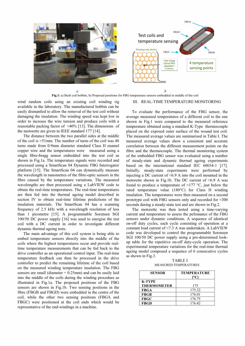
To evaluate the performance of the FBG sensor, the
average measured temperatures of a different coil to the one
shown in Fig.1 were compared to the measured reference
temperature obtained using a standard K-Type thermocouple
placed on the exposed outer surface of the wound test coil.
The measured average values are summarised in Table I. The
measured average values show a consistent and accurate
correlation between the different measurement points on the
fibre and the thermocouple. The thermal monitoring system
of the embedded FBG sensor was evaluated using a number
of steady-state and dynamic thermal ageing experiments
based on the international standard IEC 60034-1 [17].
Initially, steady-state experiments were performed by
injecting a DC current of ≈6.9 A into the coil mounted in the
motorette shown in Fig.1b. The DC current of ≈6.9 A was
found to produce a temperature of ≈177 °C, just below the
rated temperature value (180°C) for Class H winding
insulation. The temperatures were then measured on a second
prototype coil with FBG sensors only and recorded for ≈300
seconds during a steady-state test and are shown in Fig.2.
The motorette was then tested using a time-varying current and temperature to assess the pefomance of the FBG sensors under dynamic conditions. A sequence of identical on-off duty cycles, each cycle consisting of operation at a constant load current of ≈7.3 A was undertaken. A LabVIEW code was developed to control the programmable Sorensen SGI 100/50 DC power supply using a pre-determined look-up table for the repetitive on-off duty-cycle operation. The experimental temperature variations for the real-time thermal ageing model composed a sequence of 6 consecutive cycles as shown in Fig.3.
TABLE I MEASURED TEMPERATURES
SENSOR TEMPERATURE
[°C]
K-TYPE
THERMOMETER
175
FBGA 175.32
FBGB 176.01
FBGC 176.75
FBGD 176.42
FBGA
FBGD
FBGB FBGC
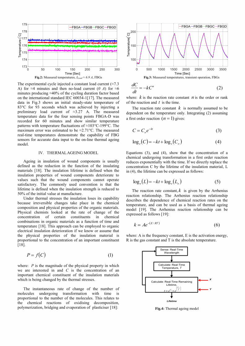
Fig.2: Measured temperatures, ILoad ≈ 6.9 A, FBGs
The experimental cycle injected a constant load current (≈7.3 A) for ≈4 minutes and then no-load current (0 A) for ≈6 minutes producing ≈40% of the cycling duration factor based on the international standard IEC 60034-1[17]. The measured data in Fig.3 shows an initial steady-state temperature of 83°C for 93 seconds which was achieved by injecting a preliminary load current of ≈3.27 A. The measured temperature data for the four sensing points FBGA-D was recorded for 60 minutes and show similar temperature patterns with temperature fluctuations of ≈103°C-199°C. The maximum error was estimated to be ≈2.71°C. The measured real-time temperatures demonstrate the capability of FBG sensors for accurate data input to the on-line thermal ageing model.
IV. THERMAL AGEING MODEL
Ageing in insulation of wound components is usually defined as the reduction in the function of the insulating materials [18]. The insulation lifetime is defined when the insulation properties of wound components deteriorate to values such that the wound components cannot operate satisfactory. The commonly used convention is that the lifetime is defined when the insulation strength is reduced to 50% of the initial value at manufacture.
Under thermal stresses the insulation loses its capability because irreversible changes take place in the chemical composition and physical properties of the organic materials. Physical chemists looked at the rate of change of the concentration of certain constituents in chemical combinations in organic materials as a function of time and temperature [18]. This approach can be employed to organic electrical insulation deterioration if we know or assume that the physical properties of the insulation material is proportional to the concentration of an important constituent [18].
CfP )1(
where: P is the magnitude of the physical property in which we are interested in and C is the concentration of an important chemical constituent of the insulation materials which is being changed by the thermal stresses.
The instantaneous rate of change of the number of molecules undergoing transformation with time is proportional to the number of the molecules. This relates to the chemical reactions of oxidising decomposition, polymerization, bridging and evaporation of plasticiser [18]:
Fig.3: Measured temperatures, transient operation, FBGs
nkCdt
dC )2(
where: k is the reaction rate constant n is the order or rank
of the reaction and t is the time.
The reaction rate constant k is normally assumed to be
dependent on the temperature only. Integrating (2) assuming
a first order reaction )1( n gives:
kt
oeCC )3(
oee CktC loglog )4(
Equations (3), and (4), show that the concentration of a chemical undergoing transformation in a first order reaction reduces exponentially with the time. If we directly replace the concentration C by the lifetime of the insulation material, L in (4), the lifetime can be expressed as follows:
oee LktL loglog )5(
The reaction rate constant, k is given by the Arrhenius
reaction relationship. The Arrhenius reaction relationship describes the dependence of chemical reaction rates on the temperature, and can be used as a basis of thermal ageing model [19]. The Arrhenius reaction relationship can be expressed as follows [19]:
RTEAek / )6(
where: A is the frequency constant, E is the activation energy, R is the gas constant and T is the absolute temperature.
Sense: Real-Time
Wavelength
Calculate: Real-Time Remaining
Lifetime,
Lifetime
Calculate: Real-Time
Temperature, T
T
C
Ceet
2
1
X
Y
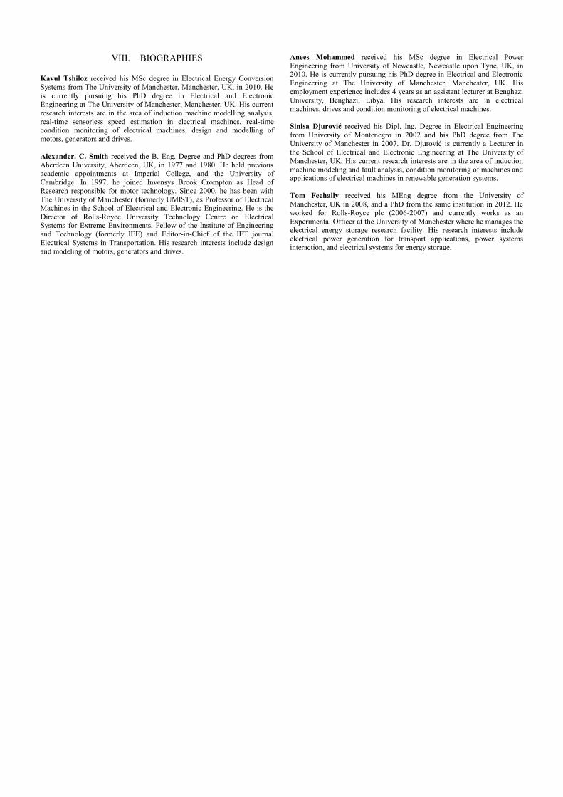
Fig.4: Thermal ageing model

Substituting the Arrhenius reaction constant, k in (5), and
rearranging we get:
T
CCte
21log )7(
This equation demonstrates that the logarithm of the
lifetime, t , is proportional to the reciprocal of the absolute
temperature T and represents the classical expression used to plot the insulation lifetime in hours as a function of the absolute temperature T. Equation (7) can be rearranged to provide a real-time lifetime model under varying temperature conditions as follows:
TC
oe teCLL/
12/log
)8(
The constants C1 and C2 can be obtained using the IEEE standard 177 [14] insulation lifetime data for standard Class A, B, F and H or the wire manufacturer [20] or by test for example [14]. The ratio (L/L0) in equation (8) represents the reduction ratio of the insulation lifetime from its initial value L0 at time t for a temperature T. This thermal lifetime model was implemented on the real-time SmartScan 04 Dynamic FBG Interrogator platform using a LabVIEW virtual instrument (VI) code architecture. The LabVIEW code was developed to measure the real-time FBG sensor wavelengths, convert the measured wavelengths into real-time temperatures and then execute the proposed real-time thermal lifetime model of the wound test coil. The thermal lifetime model flowchart is presented in Fig.4.
V. REAL-TIME LIFETIME PREDICTION
A. Performance Evaluation for Steady-State Operation
The real-time performance of the developed algorithm
was tested in a series of laboratory experiments. The laboratory motorette was operated under steady-state conditions to obtain an initial evaluation of the lifetime model.The motorette was energised using the programmable DC power supply. The thermal rating of the class H wire insulation is based on a nominal life of 20000 hours [14, 21]. The lifetime model was used to predict the remaining lifetime of the coil at the steady-state measured temperature of ≈177°C presented in Fig.2 and the average measured results are summarized in Table II. As expected the adapted thermal model produces consistent results with the nominal 20000 hours lifetime at 180
oC.
The lifetime model was then used for steady-state temperature measurements at a series of different temperature operating points of ≈157°C, ≈167°C, ≈177°C, ≈187°C and ≈197°C until the rated temperature (≈200°C) of the FBG sensor was reached. The average lifetime prediction is summarised in Table III. The obtained results demonstrate as is commonly accepted that for every ≈10°C increase in temperature, the lifetime of the insulation material decreases by ≈50% [21-22]. The predicted lifetimes shown in Table III are in close agreement with the reported lifetimes of Class H insulation materials given in the IEEE standard 177 [14].
TABLE II REAL-TIME STEADY-STATE PERFORMANCE, ≈177°C
SENSOR AVERAGE
LIFETIME [Hours]
FBGA 20085
FBGB 19886
FBGC 20584
FBGD 22010
TABLE III PERFORMANCE EVALUATION BY ≈10°C VARIATIONS
AVERAGE LIFETIME [Hours] TEMPERATURE
[°C] FBGA FBGB FBGC FBGD
≈157 84162 83382 83738 83277
≈167 42258 41240 41016 40807
≈177 20085 19886 20150 20195
≈187 10570 10295 10286 10176
≈197 5102 5061 5080 5056
B. Performance Evaluation for Transient Operation
The real-time performance of the thermal ageing model was also investigated for a sequence of 6 consecutive thermal cycles. The measured temperatures profiles shown in Fig.3 were input to the thermal ageing algorithm and the predicted lifetimes are shown in Figs.5-8. During the thermal ageing experiment, the resistance of the built coil mounted into the motorette increased from its room-temperature value of ≈0.39 Ω to ≈0.62Ω which correlates with the calculated resistance of ≈0.64Ω using the temperature coefficient of the copper of ≈0.004 per °C. Figs.5-8 show the real-time reduction in the coil lifetime as the temperature cycles up and down between ≈103 °C and ≈199 °C. The lifetime reduces sharply (marked by sections W1-6 on the figures) when the temperature increases above the rated temperature for Class H wire of 180 °C. The total lifetime reduction of the coil predicted by each Fibre Bragg Grating sensor position for the test time period of ≈60 minutes are presented in Table IV. The total remaining life predicted using the measured real-time temperature from the four sensing points was ≈72% corresponding to a total reduction in the insulation lifetime of ≈28%. The standardised method assumes a lifetime of 20000 hours and determines the wire thermal rating from this nominal life [14, 21]. If the insulation material of a wound coil operates below the wire thermal rating the lifetime (hours) increases rapidly.
TABLE IV REMAINING LIFETIME FOLLOWING THE ≈60 MINUTES CYCLE
SENSOR LIFETIME [Hours] REMAINING
LIFE [%] NOMINAL END
CYCLE
FBGA
≈198157500
142848860
72.09
FBGB
≈198157500
142887397
72.11
FBGC
≈198157500
142381614
71.85
FBGD
≈198157500
141884546
71.60
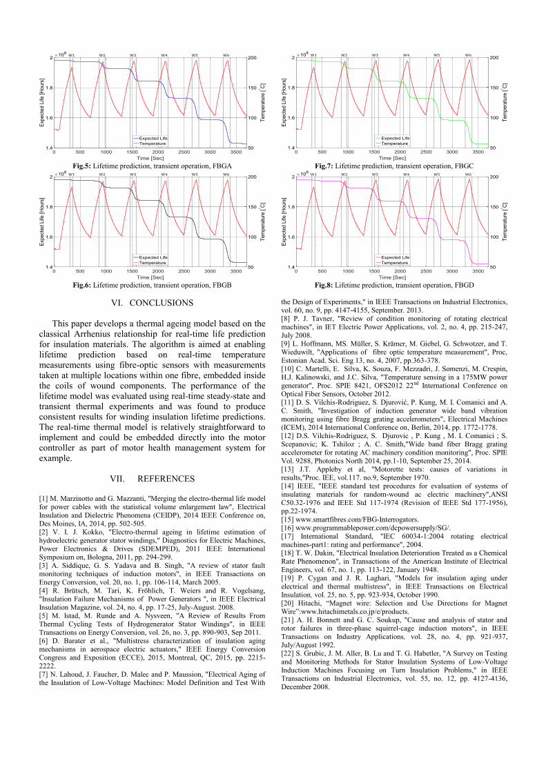
Fig.5: Lifetime prediction, transient operation, FBGA
Fig.6: Lifetime prediction, transient operation, FBGB
Fig.7: Lifetime prediction, transient operation, FBGC
Fig.8: Lifetime prediction, transient operation, FBGD
VI. CONCLUSIONS
This paper develops a thermal ageing model based on the classical Arrhenius relationship for real-time life prediction for insulation materials. The algorithm is aimed at enabling lifetime prediction based on real-time temperature measurements using fibre-optic sensors with measurements taken at multiple locations within one fibre, embedded inside the coils of wound components. The performance of the lifetime model was evaluated using real-time steady-state and transient thermal experiments and was found to produce consistent results for winding insulation lifetime predictions. The real-time thermal model is relatively straightforward to implement and could be embedded directly into the motor controller as part of motor health management system for example.
VII. REFERENCES [1] M. Marzinotto and G. Mazzanti, "Merging the electro-thermal life model for power cables with the statistical volume enlargement law", Electrical Insulation and Dielectric Phenomena (CEIDP), 2014 IEEE Conference on,
Des Moines, IA, 2014, pp. 502-505. [2] V. I. J. Kokko, "Electro-thermal ageing in lifetime estimation of hydroelectric generator stator windings," Diagnostics for Electric Machines, Power Electronics & Drives (SDEMPED), 2011 IEEE International Symposium on, Bologna, 2011, pp. 294-299. [3] A. Siddique, G. S. Yadava and B. Singh, "A review of stator fault monitoring techniques of induction motors", in IEEE Transactions on Energy Conversion, vol. 20, no. 1, pp. 106-114, March 2005. [4] R. Brütsch, M. Tari, K. Fröhlich, T. Weiers and R. Vogelsang, "Insulation Failure Mechanisms of Power Generators ", in IEEE Electrical Insulation Magazine, vol. 24, no. 4, pp. 17-25, July-August. 2008. [5] M. Istad, M. Runde and A. Nysveen, "A Review of Results From Thermal Cycling Tests of Hydrogenerator Stator Windings", in IEEE Transactions on Energy Conversion, vol. 26, no. 3, pp. 890-903, Sep 2011. [6] D. Barater et al., "Multistress characterization of insulation aging mechanisms in aerospace electric actuators," IEEE Energy Conversion Congress and Exposition (ECCE), 2015, Montreal, QC, 2015, pp. 2215-2222.
[7] N. Lahoud, J. Faucher, D. Malec and P. Maussion, "Electrical Aging of the Insulation of Low-Voltage Machines: Model Definition and Test With
the Design of Experiments," in IEEE Transactions on Industrial Electronics, vol. 60, no. 9, pp. 4147-4155, September. 2013. [8] P. J. Tavner, "Review of condition monitoring of rotating electrical machines", in IET Electric Power Applications, vol. 2, no. 4, pp. 215-247, July 2008. [9] L. Hoffmann, MS. Müller, S. Krämer, M. Giebel, G. Schwotzer, and T. Wieduwilt, "Applications of fibre optic temperature measurement", Proc, Estonian Acad. Sci. Eng 13, no. 4, 2007, pp.363-378. [10] C. Martelli, E. Silva, K. Souza, F. Mezzadri, J. Somenzi, M. Crespin,
H.J. Kalinowski, and J.C. Silva, "Temperature sensing in a 175MW power generator", Proc. SPIE 8421, OFS2012 22nd International Conference on Optical Fiber Sensors, October 2012. [11] D. S. Vilchis-Rodriguez, S. Djurović, P. Kung, M. I. Comanici and A. C. Smith, "Investigation of induction generator wide band vibration monitoring using fibre Bragg grating accelerometers", Electrical Machines (ICEM), 2014 International Conference on, Berlin, 2014, pp. 1772-1778. [12] D.S. Vilchis-Rodriguez, S. Djurovic , P. Kung , M. I. Comanici ; S. Scepanovic; K. Tshiloz ; A. C. Smith,"Wide band fiber Bragg grating accelerometer for rotating AC machinery condition monitoring", Proc. SPIE Vol. 9288, Photonics North 2014, pp.1-10, September 25, 2014. [13] J.T. Appleby et al, "Motorette tests: causes of variations in results,"Proc. IEE, vol.117. no.9, September 1970. [14] IEEE, "IEEE standard test procedures for evaluation of systems of insulating materials for random-wound ac electric machinery",ANSI C50.32-1976 and IEEE Std 117-1974 (Revision of IEEE Std 177-1956), pp.22-1974.
[15] www.smartfibres.com/FBG-Interrogators. [16] www.programmablepower.com/dcpowersupply/SG/. [17] International Standard, "IEC 60034-1:2004 rotating electrical machines-part1: rating and performance", 2004. [18] T. W. Dakin, "Electrical Insulation Deterioration Treated as a Chemical Rate Phenomenon", in Transactions of the American Institute of Electrical Engineers, vol. 67, no. 1, pp. 113-122, January 1948. [19] P. Cygan and J. R. Laghari, "Models for insulation aging under electrical and thermal multistress", in IEEE Transactions on Electrical Insulation, vol. 25, no. 5, pp. 923-934, October 1990. [20] Hitachi, “Magnet wire: Selection and Use Directions for Magnet Wire”:www.hitachimetals.co.jp/e/products. [21] A. H. Bonnett and G. C. Soukup, "Cause and analysis of stator and rotor failures in three-phase squirrel-cage induction motors", in IEEE Transactions on Industry Applications, vol. 28, no. 4, pp. 921-937, July/August 1992. [22] S. Grubic, J. M. Aller, B. Lu and T. G. Habetler, "A Survey on Testing and Monitoring Methods for Stator Insulation Systems of Low-Voltage
Induction Machines Focusing on Turn Insulation Problems," in IEEE Transactions on Industrial Electronics, vol. 55, no. 12, pp. 4127-4136, December 2008.
VIII. BIOGRAPHIES Kavul Tshiloz received his MSc degree in Electrical Energy Conversion Systems from The University of Manchester, Manchester, UK, in 2010. He is currently pursuing his PhD degree in Electrical and Electronic Engineering at The University of Manchester, Manchester, UK. His current research interests are in the area of induction machine modelling analysis, real-time sensorless speed estimation in electrical machines, real-time condition monitoring of electrical machines, design and modelling of motors, generators and drives.
Alexander. C. Smith received the B. Eng. Degree and PhD degrees from Aberdeen University, Aberdeen, UK, in 1977 and 1980. He held previous academic appointments at Imperial College, and the University of Cambridge. In 1997, he joined Invensys Brook Crompton as Head of Research responsible for motor technology. Since 2000, he has been with The University of Manchester (formerly UMIST), as Professor of Electrical Machines in the School of Electrical and Electronic Engineering. He is the Director of Rolls-Royce University Technology Centre on Electrical Systems for Extreme Environments, Fellow of the Institute of Engineering
and Technology (formerly IEE) and Editor-in-Chief of the IET journal Electrical Systems in Transportation. His research interests include design and modeling of motors, generators and drives.
Anees Mohammed received his MSc degree in Electrical Power Engineering from University of Newcastle, Newcastle upon Tyne, UK, in
2010. He is currently pursuing his PhD degree in Electrical and Electronic Engineering at The University of Manchester, Manchester, UK. His employment experience includes 4 years as an assistant lecturer at Benghazi University, Benghazi, Libya. His research interests are in electrical machines, drives and condition monitoring of electrical machines.
Sinisa Djurović received his Dipl. Ing. Degree in Electrical Engineering from University of Montenegro in 2002 and his PhD degree from The University of Manchester in 2007. Dr. Djurović is currently a Lecturer in the School of Electrical and Electronic Engineering at The University of Manchester, UK. His current research interests are in the area of induction machine modeling and fault analysis, condition monitoring of machines and applications of electrical machines in renewable generation systems.
Tom Feehally received his MEng degree from the University of Manchester, UK in 2008, and a PhD from the same institution in 2012. He worked for Rolls-Royce plc (2006-2007) and currently works as an Experimental Officer at the University of Manchester where he manages the
electrical energy storage research facility. His research interests include electrical power generation for transport applications, power systems interaction, and electrical systems for energy storage.