Embed Size (px)
Citation preview
Real-Time Refraction Through Deformable Objects
Manuel M. Oliveira∗Instituto de Informatica
UFRGS
Maicon Brauwers†
Instituto de InformaticaUFRGS
Figure 1: Armadillo model refracting a distant environment rendered using ray tracing (left) and using our technique (center). JumpingArmadillo rendered with our technique (right). Our approach requires no preprocessing, allowing real-time rendering of deforming objects.
Abstract
Light refraction is an important optical phenomenon whose simu-lation greatly contributes to the realism of synthesized images. Al-though ray tracing can correctly simulate light refraction, doing itin real time still remains a challenge. This work presents an image-space technique to simulate the refraction of distant environmentsin real time. Contrary to previous approaches for interactive refrac-tion at multiple interfaces, the proposed technique does not requireany preprocessing. As a result, it can be directly applied to objectsundergoing shape deformations, which is a common and importantfeature for character animation in computer games and movies. Ourapproach is general in the sense that it can be used with any objectrepresentation that can be rasterized on a programmable GPU. It isbased on an efficient ray-intersection procedure performed against adynamic depth map and carried out in 2D texture space. We demon-strate the effectiveness of our approach by simulating refractionsthrough animated characters composed of several hundred thousandpolygons in real time.
CR Categories: I.3.7 [Computer Graphics]: Three-DimensionalGraphics and Realism
Keywords: image-space refraction, real-time rendering, de-formable objects, image-based rendering.
∗e-mail:[email protected]†e-mail:[email protected]
1 Introduction
The synthesis of photorealistic images has long been one of themajor goals in computer graphics. In its pursuit, researchers haveproposed different strategies for simulating the complex interac-tion between light and scene elements. For translucent objects,light refraction is an important optical phenomenon whose simula-tion significantly contributes to the realism of synthesized images.While ray tracing [Whitted 1980] can correctly simulate light re-fraction, its computational cost is prohibitive for real-time applica-tions, even when acceleration techniques are used. Thus, severaltechniques for rendering approximate refractions at a single inter-face have been proposed for use in applications where speed tendsto be more important than accuracy [Oliveira 2000; Lindholm et al.2001; Schmidt 2003]. More recently, Wyman [Wyman 2005a] pre-sented an interactive technique for approximating refraction of dis-tant environments at two interfaces that produces quite impressiveresults. The images usually look very similar to the ones renderedwith a ray tracer. However, the technique requires informationabout some distance measured along the normal direction at eachvertex of model. This limits its use in applications where charac-ters may undergo non-rigid transformations, vertex morphing andskinning, which are common in games.
This paper presents a technique for approximating the refraction ofdistant environments at two interfaces in real time. Our approachwas inspired by the work of Wyman [Wyman 2005a], but contraryto previous techniques for interactive simulation of refraction atmultiple interfaces [Wyman 2005a; Genevaux et al. 2006], it re-quires no preprocessing. As a result, it can be directly applied tomodels undergoing shape deformations and is general in the sensethat it can be used with any object representation that can be ras-terized on a programmable GPU. This flexibility is achieved usingan efficient ray-intersection procedure performed against a dynamicdepth map and carried out in 2D texture space. Besides supportingdynamic geometry, the proposed approach requires less memory(no need to store and send per-vertex distances to the GPU). Fig-ure 1 illustrates the use of our technique applied to the Armadillo
Copyright © 2007 by the Association for Computing Machinery, Inc. Permission to make digital or hard copies of part or all of this work for personal or classroom use is granted without fee provided that copies are not made or distributed for commercial advantage and that copies bear this notice and the full citation on the first page. Copyrights for components of this work owned by others than ACM must be honored. Abstracting with credit is permitted. To copy otherwise, to republish, to post on servers, or to redistribute to lists, requires prior specific permission and/or a fee. Request permissions from Permissions Dept, ACM Inc., fax +1 (212) 869-0481 or e-mail [email protected]. I3D 2007, Seattle, Washington, April 30 – May 02, 2007. © 2007 ACM 978-1-59593-628-8/07/0004 $5.00
89
model on different poses. On the left, one sees an image renderedusing a ray tracer [Pharr and Humphreys ] and used for reference.The image in the center was rendered from the same viewpoint us-ing our technique. Note how similar they are. Except for the feet,where total internal reflection (TIR) occurs, they are virtually in-distinguishable from each other. The image on the right shows theArmadillo model during a jump, also rendered with our technique.
The main contributions of this paper include:
• A real-time technique for rendering approximate refraction ofdistant environments that is capable of handling any objectrepresentation that can be rasterized using a programmableGPU, including dynamically deforming models (Section 3);
• A new texture-space GPU-based algorithm for computing rayintersection against a depth map generated in perspective pro-jection (Section 3.2). It extends previous work presentedin [Policarpo et al. 2005], which is restricted to orthographicrepresentations of depth maps (i.e., height fields);
Section 2 discusses some related work and Section 3 provides thedetails of the proposed technique. We present some of our resultsin Section 4 and discuss limitations and possible extensions of thework in Section 5. Section 6 summarizes the paper.
2 Related Work
There have been a few initiatives to simulate refraction throughmultiple interfaces in recent years. Diefenbach and Badler [Diefen-bach and Badler 1997] render refractions through planar surfaces atinteractive rates using a multi-pass rendering approach. Heidrich etal. [Heidrich et al. 1999] store ray directions on a Lumigraph rep-resentation to render reflections and refractions on curved objects.The approach takes advantage of graphics hardware to acceleratethe rendering, but it requires the use of pre-acquired Lumigraphsand cannot handle deforming geometry.
Hakura and Snyder [Hakura and Snyder 2001] use a hybrid ap-proach for generating images of reflective and refractive objectsthat combines the use of ray tracing for local objects and hardware-supported environment maps for distant ones. While the techniqueproduces good results, it is not sufficiently fast for real-time appli-cations.
Guy and Soler [Guy and Soler 2004] presented a real-time tech-nique for rendering gems that handles approximations of severaloptical phenomena, including refraction. Their approach takes ad-vantage of the faceted shaped of processed gems, not being appli-cable to arbitrary shapes.
Genevaux et al. [Genevaux et al. 2006] simulate refractions throughseveral interfaces for static scenes. During a preprocessing stage,light paths are evaluated by tracing rays through the refractive ob-jects from many different entry directions. The resulting data as-sociates each pair (object’s surface point, incoming direction) to anoutgoing direction which will be used to sample a distant environ-ment map during runtime. The resulting table is then compressedusing spherical harmonics and uploaded onto graphics hardware forinteractive rendering. While the technique can produce nice resultsat interactive rates, the preprocessing stage prevents its use with ob-jects undergoing deformations. Moreover, its memory requirementsare relatively high (of the order of several dozens of megabytes).Due to the impossibility to precompute all possible light paths, thetechnique is prone to aliasing.
2.1 Image-Space Refraction
Wyman [Wyman 2005a] introduced an image-space technique forapproximating the refraction of distant environments at two inter-faces. Despite its simplicity, the approach produces very nice re-sults. The algorithm runs on the GPU, consisting of two passes.Conceptually, it can be described as:
• First, it renders the back-facing portion of the refractive ob-ject, saving the information about normals and depth of themost distant fragments from the camera;
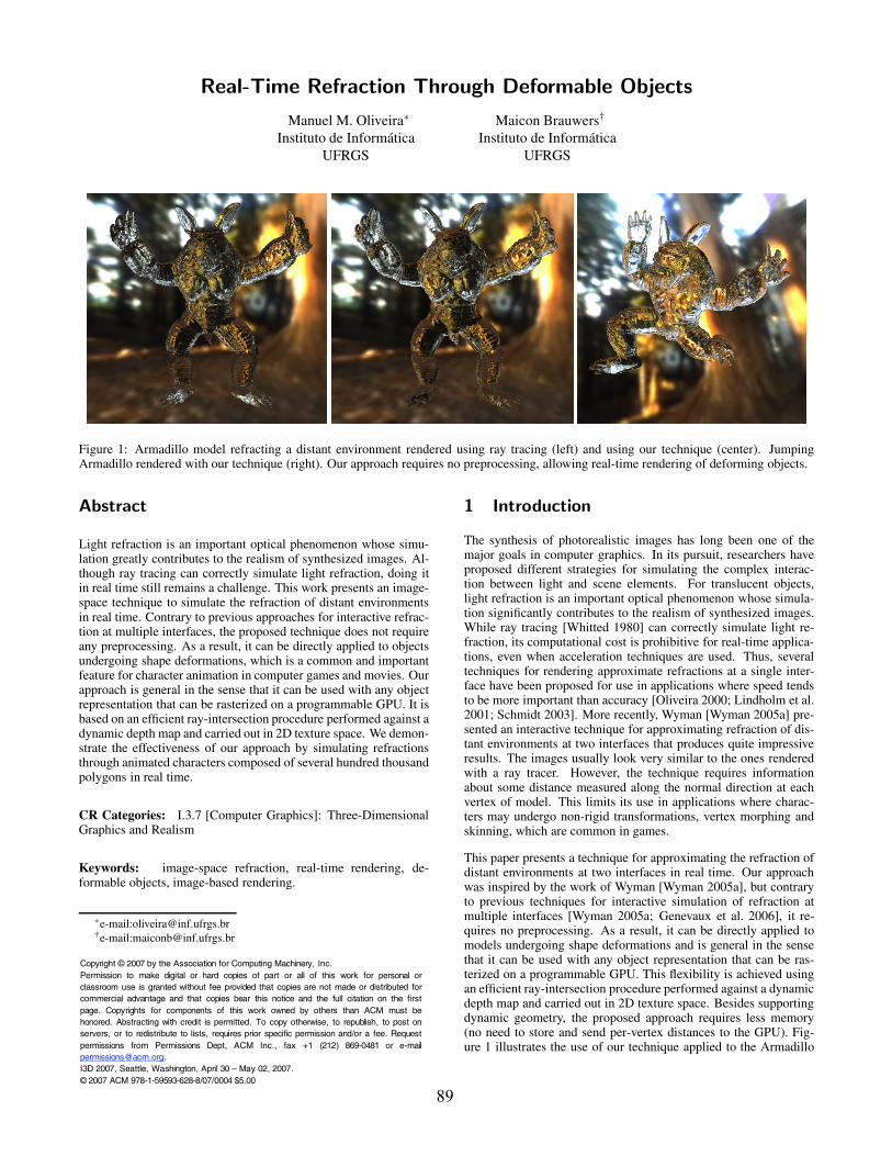
• The final image is obtained by rendering the front-facing por-tion of the object. This time, a per-fragment refracted rayT1 (Figure 2) is computed at the first interface using the cur-rent’s fragment normal (N1) and its associated viewing direc-tion (V ). T1 is then used to obtain the intersection point P2at the second interface. The coordinates of the projection ofP2 onto the camera’s image plane are used to index the savednormal map and recover N2. Finally, T1 and N2 are used tocompute the direction of T2, the refracted ray at the second in-terface, which is used to index an environment map. Figure 2illustrates this concept.
Figure 2: Refraction of distant environment through two interfaces.
Wyman [Wyman 2005a] avoids computing the intersection of T1with the saved depth map. Instead, he uses a heuristic to obtain anestimate P2 for P2. Assuming that ηo ≥ ηm, where ηo is the indexof refraction of the object and ηm is the index of refraction of thesurrounding medium, then (ηo/ηm)∈ [1,∞]. At the extrema of thisinterval, T1 would have the same direction as V and −N1, respec-tively, which are indicated in Figure 2 by the vectors dV and dN .Thus, Wyman estimates the position of point P2 along T1 by inter-polating the lengths of the vectors dV and dN (Figure 2) accordingto Equations 1 and 2. The length of dN is the distance between thefirst and second interfaces considered along the normal direction ofthe current fragment. It is pre-computed on a per-vertex basis andstored for use during runtime, when these values are interpolatedduring rasterization. The length of dV is also the distance betweenthe first and second interfaces, but this time measured along theviewing direction. It is computed for each fragment as the differ-ence between the front and the stored depth values.
P2 = P1 + dT1 (1)
whered =
θt
θidV +(1− θt
θi)dN (2)
Note that these equations have been empirically defined and al-though they can produce acceptable approximations of P2 for con-
90
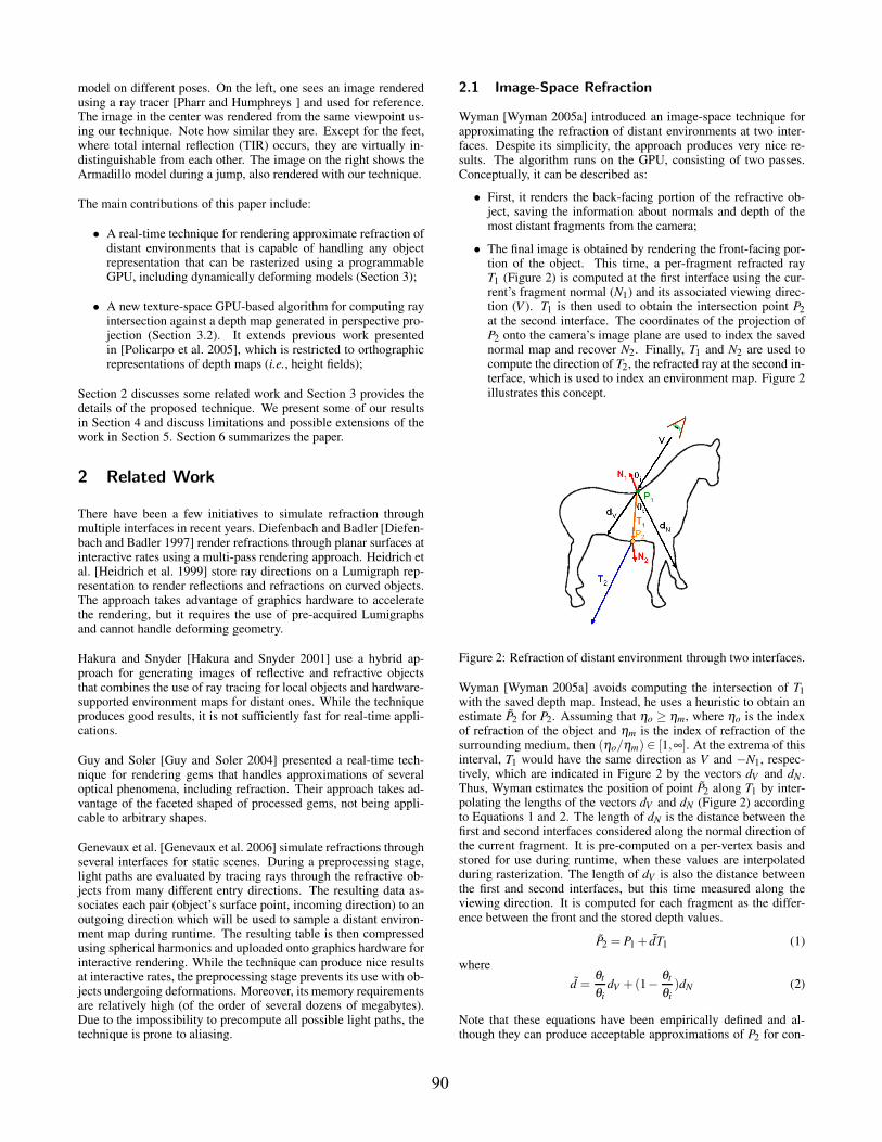
vex objects, the approximation error tends to grow for non-convexones. This situation is illustrated in Figures 2 and 3. Figure 3shows a schematic representation for the geometry (left) and nor-mals (right) of the dragon model. The error in the estimate P2 (left)lends, via its projection onto the camera’s image plane, to the re-covery of an incorrect normal N2 used to compute T2 and, subse-quently, to index the environment map. Both N2 and N2 are shownon Figure 3 (right).
Figure 3: Schematic representation for the geometry (left) and nor-mals (right) of the dragon model. The error in the estimate P2 lendsto incorrect sampling of the normal map at N2 (right), causing theenvironment map to be sampled using an incorrect T2 direction.
3 Refraction through Deformable Objects
Our approach supports the rendering deforming models by per-forming the intersection of the refracted ray T1 (Figure 2) againstthe stored depth map. This approach has some advantages com-pared to Wyman’s technique: first, it does not require any prepro-cessing and tends to produce better estimates for P2 and, conse-quently, of N2.
Our technique consists of three GPU passes:
1st pass : Similar to Wyman’s approach, it consists of renderingthe back-facing portion of the refractive object, saving the in-formation about normals and depth of the fragments with thehighest Z values;
2nd pass : It computes the depth range (minimum and maximumvalues) of the back-facing portion of the object by applyinga parallel reduction [Harris 2005] to the depth map saved inthe previous pass. At each step of the reduction, the minimumand maximum depth values from each group of four elementsare saved, respectively, in the R and G channels of the outputtexture;
3rd pass : This is the actual rendering step, which consists of ren-dering the front-facing portion of the refractive object, com-puting the refracted rays and sampling the environment map.The position of point P2 (Figure 2) is obtained computing theintersection of the refracted ray T1 with the second interfacerepresented by the perspective depth map saved in the firstpass. The search is optimized by restricting it to the rangecomputed in the second pass, and by using a new and efficientray perspective-depth-map intersection solution entirely per-formed in 2D texture space (Section 3.2). The result of the in-tersection procedure directly provides the texture coordinatesrequired to sample the normal map.
3.1 Saving Second Interface Normals and Depth
The first pass is straightforward and simply renders the back-facing geometry, saving normals and depth information. Whilenormals and depth could potentially be saved on a single RGBAtexture [Policarpo et al. 2005], we store them in two textures. Al-though this requires more memory, according to our experience,sampling the normal map using mipmapping [Williams 1983] tendsto reduce noise in the final images. This can be explained by thefact that discontinuities in the normal field may cause two neighborfragments to refract the incident rays in an incoherent manner, thusintroducing undesirable artifacts. By filtering the normals, mipmap-ping helps to minimize this problem. On the other hand, filteringa depth map tends to introduce artifacts, which can be avoided byusing a nearest neighbors sampling strategy.
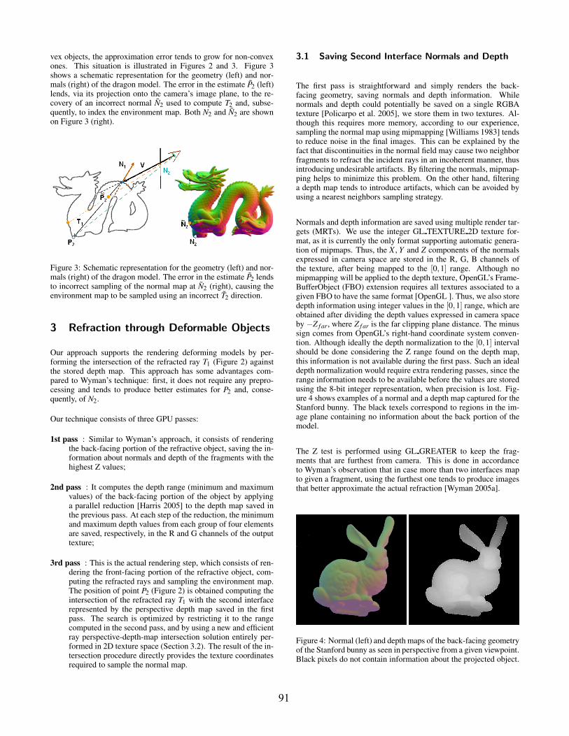
Normals and depth information are saved using multiple render tar-gets (MRTs). We use the integer GL TEXTURE 2D texture for-mat, as it is currently the only format supporting automatic genera-tion of mipmaps. Thus, the X , Y and Z components of the normalsexpressed in camera space are stored in the R, G, B channels ofthe texture, after being mapped to the [0,1] range. Although nomipmapping will be applied to the depth texture, OpenGL’s Frame-BufferObject (FBO) extension requires all textures associated to agiven FBO to have the same format [OpenGL ]. Thus, we also storedepth information using integer values in the [0,1] range, which areobtained after dividing the depth values expressed in camera spaceby −Z f ar, where Z f ar is the far clipping plane distance. The minussign comes from OpenGL’s right-hand coordinate system conven-tion. Although ideally the depth normalization to the [0,1] intervalshould be done considering the Z range found on the depth map,this information is not available during the first pass. Such an idealdepth normalization would require extra rendering passes, since therange information needs to be available before the values are storedusing the 8-bit integer representation, when precision is lost. Fig-ure 4 shows examples of a normal and a depth map captured for theStanford bunny. The black texels correspond to regions in the im-age plane containing no information about the back portion of themodel.
The Z test is performed using GL GREATER to keep the frag-ments that are furthest from camera. This is done in accordanceto Wyman’s observation that in case more than two interfaces mapto given a fragment, using the furthest one tends to produce imagesthat better approximate the actual refraction [Wyman 2005a].
Figure 4: Normal (left) and depth maps of the back-facing geometryof the Stanford bunny as seen in perspective from a given viewpoint.Black pixels do not contain information about the projected object.
91
3.2 Intersecting the Second Interface
In our approach, we compute the position of point P2 (Figure 2)by intersecting the ray refracted at the first interface (T1) againstthe depth map saved during the first pass of the algorithm. Ourapproach differs from the GPU-based ray-height-field intersectionby Policarpo et al. [Policarpo et al. 2005] in several ways: (i) weintersect the ray against dynamically generated depth maps createdunder perspective projection. Policarpo et al., on the other hand,used static depth maps created off-line under orthographic projec-tion. (ii) In our approach, although the search is performed by ad-vancing T1 in a way that resembles a binary search, the ray can onlyadvance, never recede. In [Policarpo et al. 2005], the intersectionis computed using a linear search followed by a binary search re-finement step; (iii) In our algorithm, the stored normals correspondto the back-facing portion of the model and are used for computingthe direction of refracted rays, while in relief mapping [Policarpoet al. 2005] normals are used for shading visible surfaces.
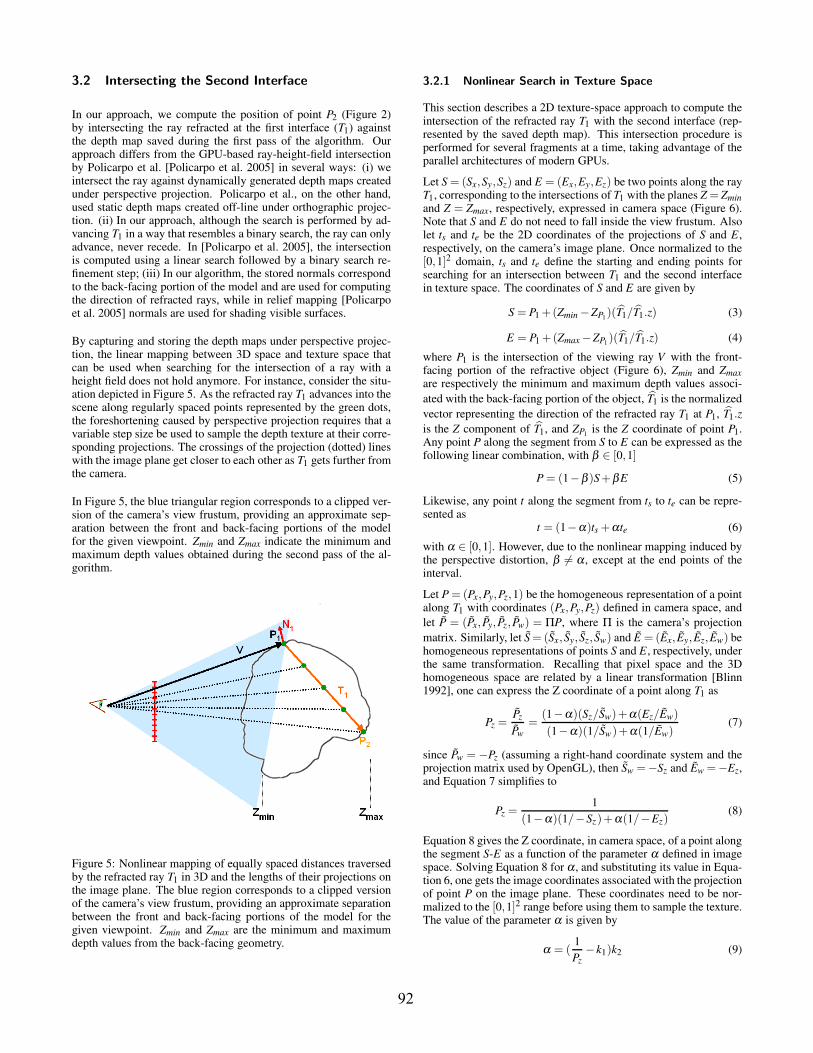
By capturing and storing the depth maps under perspective projec-tion, the linear mapping between 3D space and texture space thatcan be used when searching for the intersection of a ray with aheight field does not hold anymore. For instance, consider the situ-ation depicted in Figure 5. As the refracted ray T1 advances into thescene along regularly spaced points represented by the green dots,the foreshortening caused by perspective projection requires that avariable step size be used to sample the depth texture at their corre-sponding projections. The crossings of the projection (dotted) lineswith the image plane get closer to each other as T1 gets further fromthe camera.
In Figure 5, the blue triangular region corresponds to a clipped ver-sion of the camera’s view frustum, providing an approximate sep-aration between the front and back-facing portions of the modelfor the given viewpoint. Zmin and Zmax indicate the minimum andmaximum depth values obtained during the second pass of the al-gorithm.
Figure 5: Nonlinear mapping of equally spaced distances traversedby the refracted ray T1 in 3D and the lengths of their projections onthe image plane. The blue region corresponds to a clipped versionof the camera’s view frustum, providing an approximate separationbetween the front and back-facing portions of the model for thegiven viewpoint. Zmin and Zmax are the minimum and maximumdepth values from the back-facing geometry.
3.2.1 Nonlinear Search in Texture Space
This section describes a 2D texture-space approach to compute theintersection of the refracted ray T1 with the second interface (rep-resented by the saved depth map). This intersection procedure isperformed for several fragments at a time, taking advantage of theparallel architectures of modern GPUs.
Let S = (Sx,Sy,Sz) and E = (Ex,Ey,Ez) be two points along the rayT1, corresponding to the intersections of T1 with the planes Z = Zminand Z = Zmax, respectively, expressed in camera space (Figure 6).Note that S and E do not need to fall inside the view frustum. Alsolet ts and te be the 2D coordinates of the projections of S and E,respectively, on the camera’s image plane. Once normalized to the[0,1]2 domain, ts and te define the starting and ending points forsearching for an intersection between T1 and the second interfacein texture space. The coordinates of S and E are given by
S = P1 +(Zmin −ZP1)(T1/T1.z) (3)
E = P1 +(Zmax −ZP1)(T1/T1.z) (4)
where P1 is the intersection of the viewing ray V with the front-facing portion of the refractive object (Figure 6), Zmin and Zmaxare respectively the minimum and maximum depth values associ-ated with the back-facing portion of the object, T1 is the normalizedvector representing the direction of the refracted ray T1 at P1, T1.zis the Z component of T1, and ZP1 is the Z coordinate of point P1.Any point P along the segment from S to E can be expressed as thefollowing linear combination, with β ∈ [0,1]
P = (1−β )S+βE (5)
Likewise, any point t along the segment from ts to te can be repre-sented as
t = (1−α)ts +αte (6)
with α ∈ [0,1]. However, due to the nonlinear mapping induced bythe perspective distortion, β �= α , except at the end points of theinterval.
Let P = (Px,Py,Pz,1) be the homogeneous representation of a pointalong T1 with coordinates (Px,Py,Pz) defined in camera space, andlet P = (Px, Py, Pz, Pw) = ΠP, where Π is the camera’s projectionmatrix. Similarly, let S = (Sx, Sy, Sz, Sw) and E = (Ex, Ey, Ez, Ew) behomogeneous representations of points S and E, respectively, underthe same transformation. Recalling that pixel space and the 3Dhomogeneous space are related by a linear transformation [Blinn1992], one can express the Z coordinate of a point along T1 as
Pz =Pz
Pw=
(1−α)(Sz/Sw)+α(Ez/Ew)(1−α)(1/Sw)+α(1/Ew)
(7)
since Pw = −Pz (assuming a right-hand coordinate system and theprojection matrix used by OpenGL), then Sw =−Sz and Ew =−Ez,and Equation 7 simplifies to
Pz =1
(1−α)(1/−Sz)+α(1/−Ez)(8)
Equation 8 gives the Z coordinate, in camera space, of a point alongthe segment S-E as a function of the parameter α defined in imagespace. Solving Equation 8 for α , and substituting its value in Equa-tion 6, one gets the image coordinates associated with the projectionof point P on the image plane. These coordinates need to be nor-malized to the [0,1]2 range before using them to sample the texture.The value of the parameter α is given by
α = (1Pz
−k1)k2 (9)
92
where k1 = ( 1Sz
) and k2 = ( SzEzSz−Ez
) are constants for a given ray T1.Thus, given α , the texture coordinates needed to access the texturecan be computed from Equation 6 as
texCoord = (1−α)t ′s +αt ′e (10)
where t ′s = 0.5ts + 0.5 and t ′e = 0.5te + 0.5. The 0.5 scaling andtranslation factors simply perform the mapping from the canonicalprojection range [−1.0,1.0]2 to the 2D texture range [0.0,1.0]2. Thepseudo code shown in Algorithm 1 exemplifies the computation ofthe texture coordinates necessary to sample the depth texture at theprojection of any point P along T1.
// Given P = (Px,Py,Pz), S = (Sx,Sy,Sz) and E = (Ex,Ey,Ez)// compute the constants k1 and k2float k1 = 1/S.zfloat k2 = (S.z∗E.z)/(S.z−E.z)// Project S and E to texture coordinatesfloat4 S = mul(projectionMatrix, float4(S, 1.0f))float2 t ′s = (S.xy / S.w) * 0.5 + 0.5float4 E = mul(projectionMatrix, float4(E, 1.0f))float2 t ′e = (E.xy / E.w) * 0.5 + 0.5// Search vector in texture coordinatesfloat2 dt = (t ′e − t ′s)...// For any given point P = (Px,Py,Pz) along the ray T1// α and texCoord are computed asfloat α = (1/(P.z)−k1)∗k2float2 texCoord = t ′s +α ∗dt
Algorithm 1: Pseudo code for computing the texture coordi-nates for sampling the depth texture at the projection of a pointP along T1.
3.3 Conservative Binary Search
In relief mapping [Policarpo et al. 2005], a two-stage approachis used to perform ray-height-field intersection in texture space:first, a linear search is used to identify the neighborhood aroundthe intersection point, which is subsequently refined using a binarysearch. Since the goal of that technique is to map fine details togeometric surfaces facing the camera, the ability to intersect suchdelicate structures is crucial, thus justifying the cost of the linearsearch. When simulating refraction, however, the depth map rep-resents surfaces hidden from the camera, making the applicationmore tolerant to the missing of thin structures when compared torelief mapping. Moreover, when rendering non-convex refractiveobjects, more than two interfaces may project onto any given frag-ment, but our technique only stores the furthest one. That meansthat for the case of non-convex objects, one has only an approxi-mate representation for the second interface. As such, we avoid theuse of a linear search as it incurs in an extra cost while, accord-ing to our experience, the images produced with and without it arevirtually indistinguishable from each other.
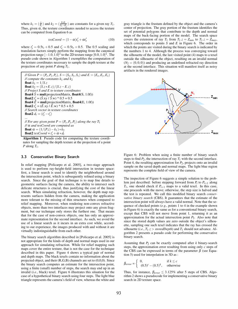
The binary search algorithm described in [Policarpo et al. 2005] isnot appropriate for the kinds of depth and normal maps used in ourapproach for simulating refraction. While for relief mapping suchmaps cover the entire texture, that is not the case for the techniquedescribed in this paper. Figure 4 shows a typical pair of normaland depth maps. The black texels contain no information about theprojected object, and their (R,G,B) channels are set to (0,0,0). Sincethe binary search computes an estimate for the intersection point,using a finite (small) number of steps, the search may end up in aninvalid (i.e., black) texel. Figure 6 illustrates this situation for thecase of a hypothetical binary search using four steps. The light bluetriangle represents the camera’s field of view, whereas the white and
gray triangle is the frustum defined by the object and the camera’scenter of projection. The gray portion of the frustum identifies theset of potential polygons that contribute to the depth and normalmaps of the back-facing portion of the model. The search spacecovers the extension of ray T1 from T1.z = Zmin to T1.z = Zmax,which corresponds to points S and E in Figure 6. The order inwhich the points are visited during the binary search is indicated bythe numbers 1 to 4. Although the process was converging towardthe silhouette of the model, the last visited point (4) maps to a texeloutside the silhouette of the object, resulting on an invalid normal(N2 = (0,0,0)) and producing an undefined refracted ray directionat the second interface. This situation will manifest itself as noisyartifacts in the rendered images.
Figure 6: Problem when using a finite number of binary searchsteps to find P2, the intersection of ray T1 with the second interface.Point 4, the resulting approximation for P2, projects onto an invalidsample on the saved depth and normal maps. The light blue regionrepresents the complete field of view of the camera.
The inspection of Figure 6 suggests a simple solution to the prob-lem just described: before stepping forward from Pi to Pi+1 alongT1, one should check if Pi+1 maps to a valid texel. In this case,one proceeds with the move; otherwise, the step size is halved andthe test is repeated. We call this modified binary search conser-vative binary search (CBS). It guarantees that the estimate of theintersection point will always have a valid normal. Note that the se-quence of checked points (e.g., points 1 to 4 in the example shownin Figure 6) is exactly the same as for a conventional binary search,except that CBS will not move from point 1, returning it as anapproximation for the actual intersection point P2. Also note thatsince the stored depth values are zero outside the object’s silhou-ette, sampling one such texel indicates that the ray has crossed thesilhouette (i.e., T1.z > storedDepth) and T1 should not advance. Al-gorithm 2 presents a pseudo code for performing the conservativebinary search.
Assuming that P2 can be exactly computed after k binary-searchsteps, the approximation error resulting from using only c steps ofthe CBS can be expressed in terms of the parameter β (see Equa-tion 5) used for interpolation in 3D as :
βerror ={
0, if k ≤ c(0.5)c − (0.5)k , otherwise
Thus, for instance, βerror ≤ 3.125% after 5 steps of CBS. Algo-rithm 2 shows a pseudocode for implementing a conservative binarysearch in 2D texture space.
93
// variables k1, k2, t ′s and dt were computed in Algorithm 1// initialize P2 with S and compute the search range in 3Dfloat3 P2 = Sfloat3 dv = (E −S)// start the conservative binary search loopfor (i=0; i < conservative binary search steps; i++) {
dv∗ = 0.5float P.z = P2.z+dv.zfloat α = (1/(P.z)−k1)∗k2float2 texCoord = t ′s +α ∗dt// sample depth stored in the texturestoredDepth = f1tex2D(DepthTex,texCoord)storedDepth *= Z f ar // recover a positive Z value// check if it is ok to advance// invalid texels have depth = 0.0if (−P.z < storedDepth) {
P2+ = dv}
// now use texCoord to sample N2 from the normal texture// then compute T2 and sample the environment map.// Use the resulting color to shade the fragment or use a// Fresnel approximation to combine reflection and refraction...}
Algorithm 2: Pseudo code for a conservative binary search in2D texture space. The negative sign in −P.z (if statement) com-pensates for the fact that OpenGL uses a right-hand coordinatesystem.
4 Results
We have implemented the refraction technique described in the pa-per as a set of shaders written in Cg [Mark et al. 2003]. The hostprogram was written in C++ and OpenGL. Both depth and nor-mal maps saved during the first pass were stored as 32-bit-per-texelRGBA textures. We used our technique to render the approximaterefraction of distant environments through several geometric mod-els and visually compared these results to the ones obtained us-ing three other techniques: single-interface refraction (SIR), image-space refraction (ISR) [Wyman 2005a], and ray tracing (RT) [Whit-ted 1980]. The single-interface refraction technique was imple-mented as described in [Fernando and Kilgard 2003]. For ISR, weused the shaders available at Wyman’s website [Wyman 2006]. Theray-traced images were generated with pbrt [Pharr and Humphreys] with 32 samples per pixel. For all images shown in the paper weset the material index of refraction to 1.2. All examples renderedwith our technique, including the accompanying video, were pro-duced using 5 steps of the conservative binary search.
Figure 1 shows refractions through the Armadillo model. On theleft, one sees a ray traced image used for reference. The image inthe center was rendered using our technique from the same view-point. Note the similarity between them. The differences, basicallynoticeable on the feet, are primarily due to the occurrence of totalinternal reflection (TIR), which is not simulated by the current ver-sion of our technique. The image on the right shows the Armadilloduring a jump, also rendered using our technique. The accompany-ing video was recorded in real time and shows several examples ofmodels undergoing deformations.
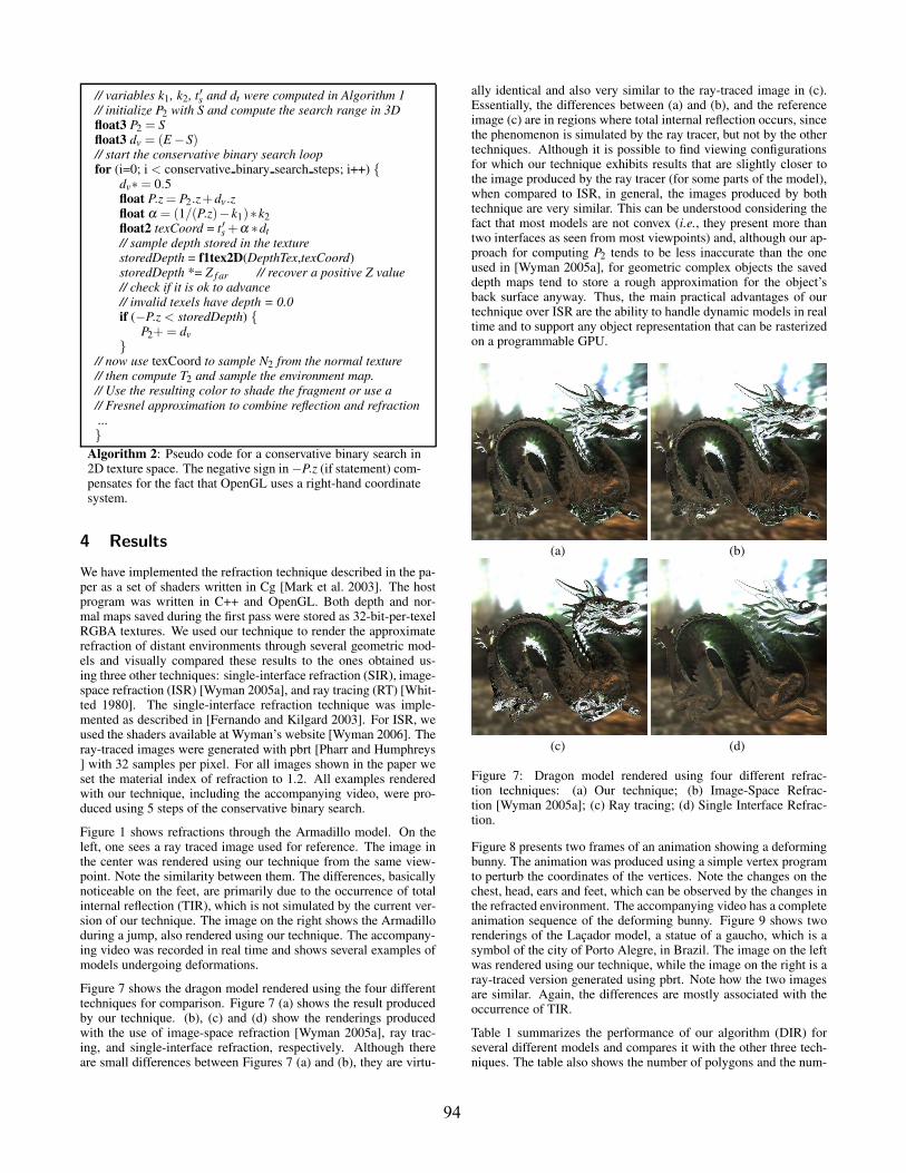
Figure 7 shows the dragon model rendered using the four differenttechniques for comparison. Figure 7 (a) shows the result producedby our technique. (b), (c) and (d) show the renderings producedwith the use of image-space refraction [Wyman 2005a], ray trac-ing, and single-interface refraction, respectively. Although thereare small differences between Figures 7 (a) and (b), they are virtu-
ally identical and also very similar to the ray-traced image in (c).Essentially, the differences between (a) and (b), and the referenceimage (c) are in regions where total internal reflection occurs, sincethe phenomenon is simulated by the ray tracer, but not by the othertechniques. Although it is possible to find viewing configurationsfor which our technique exhibits results that are slightly closer tothe image produced by the ray tracer (for some parts of the model),when compared to ISR, in general, the images produced by bothtechnique are very similar. This can be understood considering thefact that most models are not convex (i.e., they present more thantwo interfaces as seen from most viewpoints) and, although our ap-proach for computing P2 tends to be less inaccurate than the oneused in [Wyman 2005a], for geometric complex objects the saveddepth maps tend to store a rough approximation for the object’sback surface anyway. Thus, the main practical advantages of ourtechnique over ISR are the ability to handle dynamic models in realtime and to support any object representation that can be rasterizedon a programmable GPU.
(a) (b)
(c) (d)
Figure 7: Dragon model rendered using four different refrac-tion techniques: (a) Our technique; (b) Image-Space Refrac-tion [Wyman 2005a]; (c) Ray tracing; (d) Single Interface Refrac-tion.
Figure 8 presents two frames of an animation showing a deformingbunny. The animation was produced using a simple vertex programto perturb the coordinates of the vertices. Note the changes on thechest, head, ears and feet, which can be observed by the changes inthe refracted environment. The accompanying video has a completeanimation sequence of the deforming bunny. Figure 9 shows tworenderings of the Lacador model, a statue of a gaucho, which is asymbol of the city of Porto Alegre, in Brazil. The image on the leftwas rendered using our technique, while the image on the right is aray-traced version generated using pbrt. Note how the two imagesare similar. Again, the differences are mostly associated with theoccurrence of TIR.
Table 1 summarizes the performance of our algorithm (DIR) forseveral different models and compares it with the other three tech-niques. The table also shows the number of polygons and the num-
94
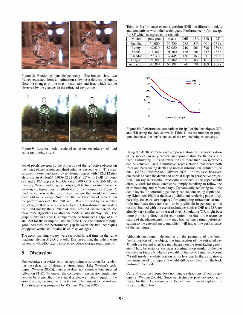
Figure 8: Rendering dynamic geometry. The images show twoframes extracted from an animation showing a deforming bunny.Note the changes on the chest, head, ears and feet, which can beobserved by the changes in the refracted environment.
Figure 9: Lacador model rendered using our technique (left) andusing ray tracing (right).
ber of pixels covered by the projection of the refractive objects onthe image plane (second and third columns, respectively). The mea-surements were performed by rendering images with 512x512 pix-els using an Athlon64 3500+ (2.21 GHz) PC with 2 GB of mem-ory and a PCI express 16x GeForce 7800 GTX with 256 MB ofmemory. When rendering each object, all techniques used the sameviewing configurations, as illustrated in the example of Figure 7.Each object was scaled to a maximum size that would still com-pletely fit in the image. Note from the last two rows of Table 1 thatthe performances of DIR, ISR and SIR are limited by the numberof polygons that need to be sent to GPU, transformed and raster-ized, and not by the number of pixel covered on the screen (forthese three algorithms we store the models using display lists). Thegraph shown in Figure 10 compares the performance (in fps) of DIRand ISR for the examples listed in Table 1. As the number of poly-gons increases, the performance gap between the two techniquesdisappear, while DIR retains its extra advantages.
The accompanying videos were recorded in real time on the samemachine, also at 512x512 pixels. During editing, the videos wereresized to 400x400 pixels in order to reduce storage requirements.
5 Discussion
Our technique provides only an approximate solution for render-ing the refraction of distant environments. Like Wyman’s tech-nique [Wyman 2005a], ours also does not simulate total internalreflection (TIR). Whenever the computed transmission angle hap-pens to be bigger than the critical angle, we make it equal to thecritical angle, causing the refracted ray to be tangent to the surface.This strategy was proposed by Wyman [Wyman 2005a].
Table 1: Performance of our algorithm (DIR) on different modelsand comparison with other techniques. Performance in fps, exceptfor RT which is expressed in seconds.
Model polygons pixels DIR ISR SIR RTBuddha 50,000 56,739 288 345 601 151 sBunny 69,630 89,050 210 261 390 139 sVenus 100,000 91,360 166 204 317 137 s
Lacador 153,372 37,445 156 163 311 60 sDragon 250,000 113,845 80 83 161 286 s
Armadillo 345,944 66,191 74 78 169 105 s
Figure 10: Performance comparison (in fps) of the techniques DIRand ISR using the data shown in Table 1. As the number of poly-gons increase, the performances of the two techniques converge.
Using the depth buffer to save a representation for the back portionof the model can only provide an approximation for the back sur-face. Simulating TIR and refractions at more than two interfacescan be achieved using a multilayer representation that stores bothfront and back-facing depth and normal information, similar to theone used in [Policarpo and Oliveira 2006]. In this case, however,one needs to save the depth and normal maps in perspective projec-tion. Our ray-intersection procedure described in the paper woulddirectly work for these extensions, simply requiring to follow theextra bouncing and refracted rays. Dynamically acquiring multipledepth layers for deforming geometry can be done using depth peel-ing [Mammen 1989] at the cost of additional rendering passes. Ap-parently, the extra cost required for computing refractions at mul-tiple interfaces does not seem to be justifiable in general, as theresults obtained with the use of techniques such as DIR and ISR arealready very similar to ray-traced ones. Simulating TIR might be amore promising direction for exploration, but due to the recursivenature of the phenomenon, rays may bounce many times before es-caping to the external medium, which will impact the performanceof the technique.
Although uncommon, depending on the geometry of the front-facing portion of the object, the intersection of the refracted rayT1 with the second interface may happen on the front-facing geom-etry. Thus, for instance, consider a configuration similar to the onedepicted in Figure 6, where T1 would hit the second interface (pointP2) still inside the white portion of the frustum. In these situations,the normal used to compute T2 would still be sampled from the backportion of the model.
Currently, our technique does not handle refractions of nearby ge-ometry [Wyman 2005b]. Since our technique provides good esti-mates for the 3D coordinates of P2, we would like to explore thissubject in the future.
95
6 Conclusion
We have presented a real-time technique for rendering approximaterefractions of distant environments through objects. Unlike previ-ous techniques, our approach can be directly applied to models un-dergoing shape deformation as well as to any object representationthat can be rasterized on a GPU. Also, our approach needs no pre-processing and requires less memory than competing techniques.
We introduced an efficient GPU algorithm for computing ray inter-section against a depth image represented in perspective projection.The search for the intersection is performed in 2D texture space.We have also presented conservative binary search, a variation ofthe binary search algorithm for 2D texture space that avoids sam-pling invalid texels. For this, we presented a bound on the errorassociated with its conservative estimation.
We have demonstrated the effectiveness of our approach by render-ing and animating several models consisting of different number ofpolygons. We have shown that as the number of polygons of the re-fractive object increases, the performances of ISR [Wyman 2005a]and of our approach converge. Our technique, however, is moregeneral in the sense it can be directly applied to any kind of modelrepresentation that can be rasterized.
A possible way of accelerating our technique is to avoid the parallelreduction (second pass of the algorithm), using the limits of theobject’s bounding box as Zmin and Zmax, since these are only usedto constrain the search space. We would also like to explore thesimulation of total internal reflection, as it is currently the biggestcause of differences between images rendered with our techniqueand ray-traced ones.
Acknowledgments
We would like to thank the anonymous reviewers for their insightfulsuggestions. The Lacador model was provided by LdSM-UFRGS(http://www.ufrgs.br/ndsm/). The Armadillo, dragon and bunnymodels were provided by the Stanford 3D scanning repository.NVIDIA donated the GeForce 7800 GTX video card used in thisresearch. This work was partially supported by Microsoft Brazil.
References
BLINN, J. 1992. Hyperbolic interpolation. IEEE Computer Graph-ics and Applications 12, 4, 89–94.
DIEFENBACH, P., AND BADLER, N. 1997. Multi-pass pipelinerendering: Realism for dynamic environments. In Proc. of I3D1997, ACM Press, 59–70.
FERNANDO, R., AND KILGARD, M. 2003. The Cg Tutorial. Sec-tion 7.3. Addison Wesley, 182–188.
GENEVAUX, O., LARUE, F., AND DISCHLER, J.-M. 2006. In-teractive refraction on complex static geometry using sphericalharmonics. In Proc. of I3D 2006, 145–152.
GUY, S., AND SOLER, C. 2004. Graphics gems revisited: fast andphysically-based rendering of gemstones. ACM Trans. Graph.23, 3, 231–238.
HAKURA, Z. S., AND SNYDER, J. M. 2001. Realistic reflectionsand refractions on graphics hardware with hybrid rendering andlayered environment maps. In Proc. 12th Eurographics Work-shop on Rendering Techniques, Springer-Verlag, 289–300.
HARRIS, M. 2005. Mapping Computaional Concepts to GPUs. InGPU Gems 2, Matt Pharr (editor). Addison Wesley, 493–508.
HEIDRICH, W., LENSCH, H., COHEN, M., AND SEIDEL, H.-P.1999. Light field techniqes for reflections and refractions. InProc. of EGWR 1999, Springer-Verlag, 187–196.
LINDHOLM, E., KLIGARD, M. J., AND MORETON, H. 2001. Auser-programmable vertex engine. In Proc. SIGGRAPH 2001,ACM Press, 149–158.
MAMMEN, A. 1989. Transparency and antialiasing algorithms im-plemented with the virtual pixel maps technique. IEEE Comput.Graph. Appl. 9, 4, 43–55.
MARK, W. R., GLANVILLE, R. S., AKELEY, K., AND KILGARD,M. J. 2003. Cg: a system for programming graphics hardwarein a c-like language. ACM Trans. Graph. 22, 3, 896–907.
OLIVEIRA, G., 2000. Refractive texture mapping.http://www.gamasutra.com/feautures/20001117 01.htm.
OPENGL. The opengl framebuffer object extension.http://www.opengl.org/registry/specs/EXT/framebuffer object.txt.
PHARR, M., AND HUMPHREYS, G. Physically-based ray tracing.http://www.pbrt.org/.
POLICARPO, F., AND OLIVEIRA, M. M. 2006. Relief mappingof non-height-field surface details. In Proc. of I3D 2006, ACMPress, 55–62.
POLICARPO, F., OLIVEIRA, M. M., AND COMBA, J. 2005. Real-time relief mapping on arbitrary polygonal surfaces. In Proc. ofI3D 2005, ACM Press, 155–162.
SCHMIDT, C., 2003. Simulating refraction using geometric trans-forms. Master’s thesis. CS Department. University of Utah.
WHITTED, T. 1980. An improved illumination model for shadeddisplay. Commun. ACM 23, 6, 343–349.
WILLIAMS, L. 1983. Pyramidal parametrics. In Siggraph 1983,Computer Graphics Proceedings, 1–11.
WYMAN, C. 2005. An approximate image-space approach forinteractive refraction. ACM Trans. Graph. 24, 3, 1050–1053.
WYMAN, C. 2005. Interactive image-space refraction of nearbygeometry. In Proceedings of GRAPHITE, 205–211.
WYMAN, C., 2006. Chris wyman’s website.http://www.cs.uiowa.edu/ cwyman/publications/.
96