Embed Size (px)
Citation preview
Research Collection
Master Thesis
Real-time rendering of proxy based 3D paintings using fintextures
Author(s): Imhof, Nicolas
Publication Date: 2015
Permanent Link: https://doi.org/10.3929/ethz-a-010541112
Rights / License: In Copyright - Non-Commercial Use Permitted
This page was generated automatically upon download from the ETH Zurich Research Collection. For moreinformation please consult the Terms of use.
ETH Library
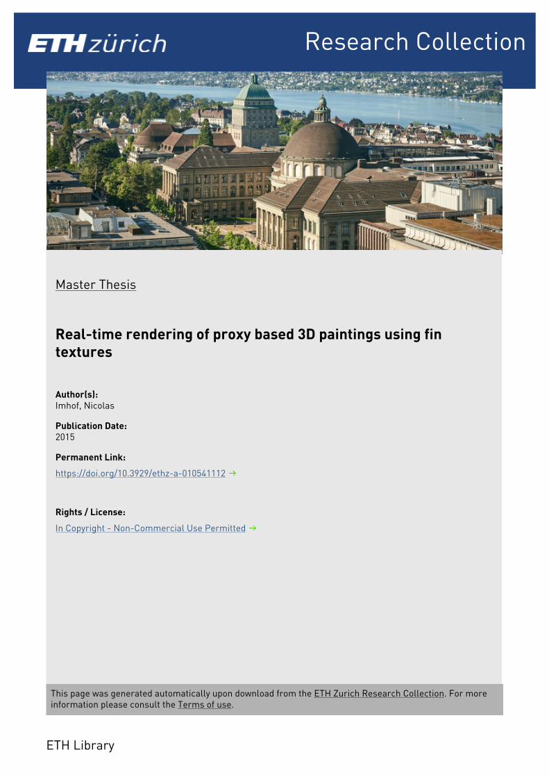
Real-time rendering of proxy based 3Dpaintings using fin textures
Nicolas Imhof
Master ThesisJuly 2015
Prof. Robert W. Sumner


Abstract
Recent advances in painterly character authoring and rendering let digital artists create char-acters represented by 3D geometry as well as 3D paint strokes embedded on and around thatgeometry. Existing methods provide intuitive authoring workflows based on 2D painting ges-tures, without constraining artists to paint directly on the geometry. Strokes painted on screenoutside of the visualized 3D mesh can be embedded in the space around that geometry. Theresulting paintings can be rendered in screen space and carry a unique visual style.In this master thesis, we are in particular interested in the 3D painting authoring and renderingprocess presented in [SSGS11]. Such existing techniques, while providing very unique stylesfor the offline rendering of 3D animations, were never adapted to interactive or even real-timeapplications. In this master thesis, we propose the first method to render complex 3D paint-ings in real-time. This novel method can directly be applied to port stylized rendering to videogames.After observing that off-surface paint strokes can be interpreted as volumetric data in the prox-imity of 3D meshes, we review existing volumetric texture techniques and show that they arenot adapted to paint strokes, which can be sparse and have a significant structure which shouldbe preserved. Taking inspiration from shell textures, we provide a method that creates relevant3D geometry and computes alpha textures to closely approximate 3D paintings using a smallnumber of polygons, that can be rendered in real-time in standard game engines.
i

ii

Master Thesis for Nicolas Imhof
Real-time rendering of proxy-based 3D paintings using fin textures
Introduction In the recent years, the computer graphics community has shown a growing interest in achieving new visual styles for computer animated movies. Significant contributions came from Disney Research's OverCoat software, developed in Zurich, allowing users to freely create complex 3D paintings. Recent interest also came from the computer game design community, where novel visual styles are a constant challenge in real-time. In that context, Disney Research Zurich and the Zurich University of the Arts (ZHdK) are collaborating in an attempt to display OverCoat paintings in real-time applications such as video games. Existing rendering techniques for OverCoat paintings are too involved to be directly applied and the student will have to approximate the 3D paintings using state of the art research in shell texture rendering.
Task Description This project contains several challenges, since OverCoat uses its own file format that is not importable in any commercial game design package, and the rendering of OverCoat scenes is so far only performable in OverCoat. Three major challenges have to be faced by the student:
Learning The student will work in close collaboration with art students and professionals from the ZHdK. Such artists have strong creative skills but cannot contribute to the technical aspects of this project. It is required to understand the needs of a non-technical user, and make the appropriate decisions on the technical side. The student has to become familiar with OverCoat and Unity in order to implement an approximation algorithm.
Implementation Being part of a long-term collaboration, the student is expected to put in application his scholar knowledge of project management, not forgetting that his code will surely be reused in the future. When experimenting with complex algorithms, small progressive increments are expected from the student for a continuous validation of his work.
Experiments The developed pipeline should be tested and experimented in collaboration with the ZHdK student and validated as fail-proof. The approximation process should be simple to use and in general provide expected and satisfying results. A final implementation running in real-time is of course the expectation of this project.
Remarks A written report and an oral presentation conclude the thesis. The thesis will be overseen and supervised by Prof. Robert W. Sumner.
Timeline
Issue: January 25th / Submission: July 25th

iv
Acknowledgements
First of all I would like to thank Disney Research for the great opportunity to write my thesis insuch an interesting research area. In addition, my deepest appreciation goes to Prof. Robert W.Sumner for his inspiring supervision, encouragement and for sharing his deep knowledge andwisdom.
Further, I wish to express my sincere gratitude to my direct advisor at Disney Research, An-toine Milliez, for the excitement and catching spirit of adventure in regard to research and hisproficient guidance with all his amazing knowledge in maths, computer graphics and animation.
In addition, I truly appreciate the creative input and artistic help from the digital artists at Dis-ney Research, namely Alessia Marra and Maurizio Nitti, who created some of the amazingOverCoat scenes that I used for my thesis.
Speaking of artists, I must thank Flurin Jenal, a talented game designer from the Zurich Uni-versity of the Arts (ZHdK), for the impressive game scenes he realised with the new methoddeveloped in this thesis.
I also would like to thank Manuel Braunschweiler, who tried to tackle the same challenge inhis bachelor thesis with a different approach. He provided me with additional material andhelpfully outlined the problems he ran into during his work.
Last but not least, I wish to thank all the people at Disney Research, especially the marvelousAnimation Group. They made me enjoy my work-place every day and contributed to my greatmotivation to work on the thesis. I believe that I could have not found another thesis being moresuitable for me.
v

vi
Contents
List of Figures ix
1. Introduction 11.1. Motivation . . . . . . . . . . . . . . . . . . . . . . . . . . . . . . . . . . . . . 11.2. Ambition . . . . . . . . . . . . . . . . . . . . . . . . . . . . . . . . . . . . . 11.3. Preliminary Investigations . . . . . . . . . . . . . . . . . . . . . . . . . . . . 21.4. Concept . . . . . . . . . . . . . . . . . . . . . . . . . . . . . . . . . . . . . . 21.5. Contribution . . . . . . . . . . . . . . . . . . . . . . . . . . . . . . . . . . . . 2
List of Tables 1
2. Related Work 32.1. Stylized Rendering in Animation . . . . . . . . . . . . . . . . . . . . . . . . . 32.2. Stylized Rendering in Interactive Applications . . . . . . . . . . . . . . . . . . 32.3. Capturing and Rendering Volumetric Shells . . . . . . . . . . . . . . . . . . . 42.4. "Kimono" Approximation . . . . . . . . . . . . . . . . . . . . . . . . . . . . 5
3. Method 73.1. Overview . . . . . . . . . . . . . . . . . . . . . . . . . . . . . . . . . . . . . 73.2. Fin Mesh Generation . . . . . . . . . . . . . . . . . . . . . . . . . . . . . . . 73.3. Capturing Fin Textures . . . . . . . . . . . . . . . . . . . . . . . . . . . . . . 9
3.3.1. Proxy Geometry Textures . . . . . . . . . . . . . . . . . . . . . . . . 103.3.2. Fin Textures . . . . . . . . . . . . . . . . . . . . . . . . . . . . . . . . 13
3.4. Fin Texture Rendering . . . . . . . . . . . . . . . . . . . . . . . . . . . . . . 143.4.1. Fin Mesh Vertex Normal Interpolation . . . . . . . . . . . . . . . . . . 14
vii
Contents
4. Results 174.1. Frame Rate . . . . . . . . . . . . . . . . . . . . . . . . . . . . . . . . . . . . 174.2. Offline Approximation Time . . . . . . . . . . . . . . . . . . . . . . . . . . . 194.3. Rendering Quality . . . . . . . . . . . . . . . . . . . . . . . . . . . . . . . . . 19
4.3.1. Results Review . . . . . . . . . . . . . . . . . . . . . . . . . . . . . . 194.3.2. Game Scenes . . . . . . . . . . . . . . . . . . . . . . . . . . . . . . . 244.3.3. Comparison with Kimono Approximation . . . . . . . . . . . . . . . . 27
5. Limitations and Future Work 31
6. Conclusion 33
A. Appendix 35A.1. Workflow Documentation . . . . . . . . . . . . . . . . . . . . . . . . . . . . . 35
A.1.1. OverCoat Interface . . . . . . . . . . . . . . . . . . . . . . . . . . . . 35A.1.2. Approximation Interface . . . . . . . . . . . . . . . . . . . . . . . . . 36A.1.3. Advanced Options . . . . . . . . . . . . . . . . . . . . . . . . . . . . 36A.1.4. Unity Import . . . . . . . . . . . . . . . . . . . . . . . . . . . . . . . 38A.1.5. Approximation Viewer . . . . . . . . . . . . . . . . . . . . . . . . . . 41
A.2. Additional Results . . . . . . . . . . . . . . . . . . . . . . . . . . . . . . . . 42
Bibliography 45
viii
List of Figures
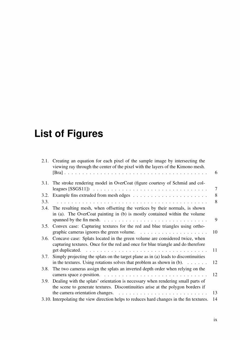
2.1. Creating an equation for each pixel of the sample image by intersecting theviewing ray through the center of the pixel with the layers of the Kimono mesh.[Bra] . . . . . . . . . . . . . . . . . . . . . . . . . . . . . . . . . . . . . . . . 6
3.1. The stroke rendering model in OverCoat (figure courtesy of Schmid and col-leagues [SSGS11]) . . . . . . . . . . . . . . . . . . . . . . . . . . . . . . . . 7
3.2. Example fins extruded from mesh edges . . . . . . . . . . . . . . . . . . . . . 83.3. . . . . . . . . . . . . . . . . . . . . . . . . . . . . . . . . . . . . . . . . . . 83.4. The resulting mesh, when offsetting the vertices by their normals, is shown
in (a). The OverCoat painting in (b) is mostly contained within the volumespanned by the fin mesh. . . . . . . . . . . . . . . . . . . . . . . . . . . . . . 9
3.5. Convex case: Capturing textures for the red and blue triangles using ortho-graphic cameras ignores the green volume. . . . . . . . . . . . . . . . . . . . 10
3.6. Concave case: Splats located in the green volume are considered twice, whencapturing textures. Once for the red and once for blue triangle and do thereforeget duplicated. . . . . . . . . . . . . . . . . . . . . . . . . . . . . . . . . . . 11
3.7. Simply projecting the splats on the target plane as in (a) leads to discontinuitiesin the textures. Using rotations solves that problem as shown in (b). . . . . . . 12
3.8. The two cameras assign the splats an inverted depth order when relying on thecamera space z-position. . . . . . . . . . . . . . . . . . . . . . . . . . . . . . 12
3.9. Dealing with the splats’ orientation is necessary when rendering small parts ofthe scene to generate textures. Discontinuities arise at the polygon borders ifthe camera orientation changes. . . . . . . . . . . . . . . . . . . . . . . . . . 13
3.10. Interpolating the view direction helps to reduces hard changes in the fin textures. 14
ix
List of Figures
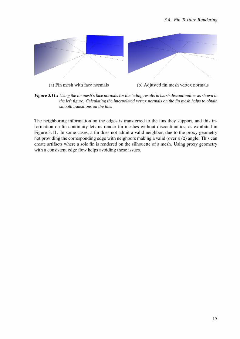
3.11. Using the fin mesh’s face normals for the fading results in harsh discontinuitiesas shown in the left figure. Calculating the interpolated vertex normals on thefin mesh helps to obtain smooth transitions on the fins. . . . . . . . . . . . . . 15
4.1. Bee scene . . . . . . . . . . . . . . . . . . . . . . . . . . . . . . . . . . . . . 204.2. Magican & Genie scene . . . . . . . . . . . . . . . . . . . . . . . . . . . . . 204.3. Dog scene . . . . . . . . . . . . . . . . . . . . . . . . . . . . . . . . . . . . . 214.4. Cat scene (backside) . . . . . . . . . . . . . . . . . . . . . . . . . . . . . . . 214.5. Cat scene (front) . . . . . . . . . . . . . . . . . . . . . . . . . . . . . . . . . 224.6. The blue paint stroke is captured by all three surrounding fins. . . . . . . . . . 234.7. The OverCoat scene (a) of painted grass is approximated using a single sub-
divided plane as input mesh. While in (b) the grass is still connected with 15layers, it clearly splits up with five layers in (c), revealing the underlying struc-ture. . . . . . . . . . . . . . . . . . . . . . . . . . . . . . . . . . . . . . . . . 23
4.8. Game scene "Jumping panda" . . . . . . . . . . . . . . . . . . . . . . . . . . 244.9. Game scene "Overdog" . . . . . . . . . . . . . . . . . . . . . . . . . . . . . . 254.10. Game scene "Attacking UFO" . . . . . . . . . . . . . . . . . . . . . . . . . . 264.11. The comparison of the "Dog" scene shows that in the old Kimono approxima-
tion the textures appear blurred, while for our new method the characteristics ofthe paint strokes are still preserved. . . . . . . . . . . . . . . . . . . . . . . . 27
4.12. A closer look at the textures highlights the differences in quality and strokecharacteristics preservation. Since the Kimono approximation solves for eachtexture pixel separately, single pixels can completely differ from their surround-ings. . . . . . . . . . . . . . . . . . . . . . . . . . . . . . . . . . . . . . . . 28
4.13. In the "Element Cube" scene the layers can become disturbingly visible in theold approximation method, while the new method provides satisfying results. . 28
4.14. In many cases the Kimono approximation runs into local minima, providingunsatisfying results. As the above pictures implies, even after several hoursof calculation time, the textures of the "cat" scene are still in a bad condition.There is no other choice then to restart the approximation process over againand hope for better results. . . . . . . . . . . . . . . . . . . . . . . . . . . . . 29
A.1. Different scales for the genie’s body and smoke are used in (a), while in (b) onlythe smoke of the genie is approximated. . . . . . . . . . . . . . . . . . . . . . 35
A.2. Approximation interface integrated in Overcoat . . . . . . . . . . . . . . . . . 37A.3. Different Unity texture settings illustrated on the blue cat. Artifacts appear at
the fins’ end in (a). No such artifacts are visible in (b). . . . . . . . . . . . . . 38A.4. Different Unity texture formats illustrated on the blue cat’s tail. . . . . . . . . 39A.5. The two Unity scripts that are necessary for the approximations to look correct.
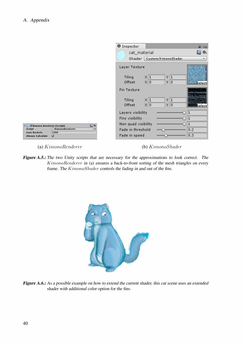
The KimonoRenderer in (a) ensures a back-to-front sorting of the mesh trian-gles on every frame. The KimonoShader controls the fading in and out of thefins. . . . . . . . . . . . . . . . . . . . . . . . . . . . . . . . . . . . . . . . . 40
A.6. As a possible example on how to extend the current shader, this cat scene usesan extended shader with additional color option for the fins. . . . . . . . . . . . 40
A.7. Modifying textures . . . . . . . . . . . . . . . . . . . . . . . . . . . . . . . . 41A.8. KimonoViewer . . . . . . . . . . . . . . . . . . . . . . . . . . . . . . . . . . 42A.9. Van Gogh scene . . . . . . . . . . . . . . . . . . . . . . . . . . . . . . . . . 43
x

List of Figures
A.10.Cat and Mouse scene - Both images show an approximation of the originalscene with additional shadow projectors. . . . . . . . . . . . . . . . . . . . . . 43
A.11.Panda scene . . . . . . . . . . . . . . . . . . . . . . . . . . . . . . . . . . . . 44A.12.Various approximated scenes . . . . . . . . . . . . . . . . . . . . . . . . . . . 44
xi

List of Figures
xii

1Introduction
1.1. Motivation
Through their unique combination of visual, narrative, auditory, and interactive elements, videogames provide an engaging medium of expression within our society. Video game exhibitions attop art museums such as the Museum of Modern Art [MoM12] and the Smithsonian AmericanArt Museum [MO12] attest to the fact that games have grown to be respected as an art formon par with film and animation. The visual design of a video game plays a significant role inthe game’s overall artistic impact. In the design phase, artists craft a vision for the game’s lookthat supports the interaction style and narrative significance of the game. For example, the softand glowing aesthetic of Flower [Che09] supports the game’s poetic nature, while the dark andgritty visuals of Heavy Rain [Cag10] enhance the game’s film noir style.
Although a game’s visuals contribute greatly to its overall feeling and impact, fully realizingthe desired artistic vision for a game within the constraints of modern game engines is oftenimpossible. Games are, by nature, interactive and rely on a sophisticated set of technologicaltools to support character models, rigging, animation, environments, camera control, lighting,texturing, and rendering within this interactive setting. The game engine, which encompassesthis technology, must deliver stunning, rendered imagery at high frame rates to support smoothinteraction. The strict real-time demand naturally requires tradeoffs in the engine’s overall vi-sual expressivity. As a result, the game engine may not accommodate the visual style envisionedfor a game, requiring alterations to conform to the engine’s technical limitations. The final lookof the game may deviate significantly from the artist’s original vision. Extending the spectrumof visual styles achievable in real-time applications is therefore an ongoing research area.
1.2. Ambition
Our work attempts to expand the aesthetic range of video game styles by reformulating costlyoffline expressive rendering methods to work in real-time using commodity game engines. Weplace special attention on the difficult case of game characters, which are particularly challeng-ing since they are animated and can be viewed from any perspective. In order to give the artistdirect control over the character’s visual style, we use a stroke-based 3D painting and animationsystem called OverCoat [SSGS11, BSS+11, BBS+13] that allows artists to craft a character’slook through painting with expressivity that is akin to creating 2D concept art. While OverCoatrequires a costly, custom, offline rendering step, we propose a new formulation that can be ren-dered in real-time while maintaining the same aesthetic quality. Since our goal is to open upnew visual styles to as many game designers as possible, we develop our work for the industrystandard Unity game engine [Uni15].
1
1. Introduction
1.3. Preliminary Investigations
Since its foundation in the year 2008, considerable interest and effort was put into non-photo-realistic rendering at Disney Research. This effort manifested itself in projects such as Over-Coat. In a presentation by Disney Research at ZHdK, in which OverCoat was introduced tothe art students, Flurin Jenal, a ZHdK game designer, envisioned combining OverCoat’s uniquevisual style with an interactive video game. He appealed with his idea to Disney Research andoriginated the initial motivation. Thereafter, Disney Research announced work on a bachelorthesis that aimed at finding a way to tackle the technical challenges. Although not perfect, theresults, accomplished by using the OverCoat approximations of that thesis in a real-time game,evinced major potential.We comment on the technical approach of said thesis in the related work chapter in section 2.4and compare the results achieved by its method and ours in section 4.3.3.
1.4. Concept
Technically, our method expands on the concept of shell textures [MN98]. For each mesh poly-gon, we generate edge polygons, or "fins", by extruding the polygon edges orthogonally off thesurface. We then provide an algorithm to generate alpha textures for the fins based on an inputOverCoat painting. We use a per-pixel normal calculation in order to fade in such polygonsalong boundary views. The method fits naturally within Unity’s rendering procedure, and onlyrequires a back-to-front polygon sort as overhead. We extend character skinning weights todeform our fin meshes to support animation.
1.5. Contribution
Our core contributions include an edge polygon representation, a rendering procedure for per-pixel boundary visibility, and a texture calculation method designed for offline stroke-basednon-photorealistic rendering methods. Taken together, our method can reproduce the painterlyaesthetic of OverCoat at real-time speeds, even on low-end devices. We show several examplesof how our method expands the range of aesthetic styles that can be achieved with a commoditygame engine.
2
2Related Work
2.1. Stylized Rendering in Animation
Non-photorealistic rendering aims at depicting a digital scene using a specific visual style.Many industrial applications exist, in particular in the context of CAD, where specific shadingalgorithms can improve the legibility of technical illustrations, as demonstrated in [GGSC98].However, most existing non-photorealistic rendering techniques were developed for a specificaesthetic intent. In particular, a large palette of methods target painterly rendering, in an effortto stylize 3D objects and characters by reproducing the look of traditional 2D paintings.
Two major research directions can be identified within painterly rendering. First, followingthe seminal work by Meier ([Mei96]), a variety of methods place particles in screen spaceor directly onto 3D geometry to act as seeds for the instantiation of paint strokes. The othermain lineage of work consists of screen space image processing methods that act on videos orrendered images. Techniques include example-based stylization [HJO+01] and screen spacestroke generation [Lit97]. We refer the reader to Hedge, Gatzidis, and Tian’s review article[HGT13] for a more exhaustive study of existing painterly rendering methods.
In our work, we wish to place the artists at the core of the stylization process so that they can di-rectly craft the desired painterly look. Offline methods such as WYSIWYG NPR ([KMM+02]),Deep Canvas ([KL03]), and OverCoat ([SSGS11]) share this goal. OverCoat’s novelty residesin the possibility to place paint strokes around meshes, which is analogous to painting in 2Doutside of strict contours, thus allowing for fluffy painterly characters to be authored and ren-dered. Recent extensions support character animation [BBS+13] while maintaining motion andtemporal coherence, which are challenging but critical qualities in non-photorealistic rendering[BBT11]. Although ideal for character stylization, OverCoat’s rendering method as well as themore elaborate one published in [BSS+11], both target offline rendering, and are not suitablefor framerate demanding applications such as video games. As such, we use the OverCoatframework as the basis for our research and develop an algorithm to reformulate OverCoat’scostly, offline, special-purpose rendering algorithm into one that is amenable to commoditygame engines in real-time.
2.2. Stylized Rendering in Interactive Applications
Some expressiveness of non-photorealistic rendering has already been leveraged in video games.In particular, emphasis has been put on flat-looking renderings, mimicking 2D celluloid anima-tions. Such a visual style was first brought to video games using painted pre-rendered flat tex-tures in Fear Effect [Pla99], and was first computed in real-time in Jet Set Radio [Kik00], thus
3
2. Related Work
pioneering the technique now commonly referred to as cel shading. Cel shading has since be-come common in real-time rendering applications such as video games. Many variations exist,using shaders to enforce a specific color scheme, simulate unrealistic lighting, or copy featurescommonly found in 2D art, such as rendering the silhouette of a character using tapered lines.
More advanced real-time stylization methods have been published in the past, aiming at achiev-ing existing non-photorealistic rendering styles in real-time. In [MKG+97], the authors proposea real-time method for line-based stylization. More specific styles can be achieved in real-time, such as hatching ([PHWF01]), line art rendering ([Elb99]) or charcoal drawing ([MG02]).These real-time non-photorealistic rendering techniques are all fantastic for replicating partic-ular, specialized styles, but offer only a restricted amount of flexibility to the artist over thefinal appearance. Fine-scale customizations in character appearance are typically not possible.Furthermore, programmable interfaces such as those inspired by cel shading require technicalskills, and are an indirect way of controlling the final look of a rendering. By targeting a 3Dpainting system that provides direct control over character stylization, we bring this new levelof stylized control to game design.
2.3. Capturing and Rendering Volumetric Shells
Paint strokes embedded around 3D characters can be interpreted as volumetric structures. Sev-eral publications have already targeted volumetric data rendering around meshes. Indeed, vol-umetric structures are inherent to realistic digital scenes, and adding hair, fur, or small-scalegeometry to the surface of a 3D character increases its visual richness. In the early days ofcomputer graphics, modeling complex structures such as fur using geometry was too complexfor state-of-the-art hardware. Kajiya and Kay proposed a seminal solution using texels [KK89]that inspired researchers to use the space surrounding a mesh, commonly referred to as shellspace, to embed renderable data.
In a similar fashion to textures that get applied to 3D models, texels with toroidal symmetrycan be deformed to fit in each shell around a mesh. Such volumetric shell textures are usedto add repetitive detail to a 3D model. Neyret extended that technique to shell textures aroundarbitrary resolution meshes to render complex natural scenes [Ney98]. Further works makinguse of shell space include [CTW+04], in which the authors define shell texture functions, thatdescribe complex volumetric materials around meshes for advanced rendering in the context ofsubsurface scattering. Porumbescu and colleagues present a bijective mapping between shellspace and texture space, called a shell map, in order to synthesize geometric detail onto meshes[PBFJ05].
These methods target offline rendering through ray-tracing or geometry generation. Meyer andNeyret [MN98] introduce a technique to slice a shell texture into layered polygons, enablingreal-time rendering of shell textures using z-buffers. Sliced, or layered shell textures were thenused for rendering fur using level of detail [Len00] and over arbitrary surfaces [LPFH01]. Thesemethods are powerful for stochastic and repetitive data like fur, but are not directly applicablein our context, since we aim at reproducing 3D paintings where every locally painted detailcontributes to the artist’s intended character design.
4

2.4. "Kimono" Approximation
In order to render 3D paintings using shell textures, we must devise a new method for refor-mulating paint strokes rendered in screen space as shell textures. Some existing techniquestarget the related problem of rendering complex 3D data acquired from screen space capture. Inparticular, [MPN+02] capture opacity hulls, which are rendered by projecting surfels onto thescreen. Further work presented in [VPM+03] provide a hardware-oriented algorithm to renderopacity light fields using a multi-pass rendering. Both methods impose specific rendering algo-rithms that target real-time lighting. Our method is designed to be compatible with commoditygame engines and only requires back-to-front polygon sorting and a one-pass OpenGL render-ing. More recently, Okabe and colleagues [ODAO15] compute 3D models of fluid in motionfrom images. These three methods must infer the shape of the captured object or phenomenonfrom the 2D views they use as input. Our "fin texture" method makes use of the 3D paintings’proxy geometry which gives the artist control over the complexity and topology of the mesh.
2.4. "Kimono" Approximation
Clearly most related to our venture is the work of Manuel Braunschweiler in [Bra]. In hisbachelor thesis, Manuel Braunschweiler approaches the challenge of depicting 3D paintingswith a multi-layered, textured mesh. Because of its nested structure, the author assigned theterm "Kimono" to the approximation method. The challenge to craft the textures for the meshis approached in a strictly mathematical way by setting up a non-linear system of equations.Several sample images of the targeted scene are captured from different view perspectives andused to derive per-pixel based equations as visualized by Figure 2.1. The system of equationsis then solved in a least squares sense.
Although mathematically elegant, this approach faces some serious drawbacks. First, solvingsuch a system with millions of equations requires a long offline computation time of severalhours. Second, the approximation process often runs into local minima and is not trivial to setup since there are several decisions to be made by the user. In terms of quality, the method doesnot preserve the inherent structure of the paint strokes. Instead, the resulting textures appearblurred and various artifacts show up. The most disruptive issue is that the object’s silhouettesreveal the underlying layered structure.
Likewise, we support multiple layers in our approach; however, they are not the pillar of ourmethod. In fact, we show in section 4.3 that good results can be achieved using just one singlelayer. Furthermore, we use "fin textures" together with per-fragment fading in and out to hidethe layers at the silhouettes. The most noticeable difference is how we solve for the textures.We apply various transformations to the splats of the paint strokes in order to be able to directlyrender parts of the texture, which helps us in preserving the intended structure of the paintstrokes. In section 4.3, we compare the results achieved by Kimono and by our method, andshow an increase in quality and reliability as well as a reduction in offline pre-computation time.
5

2. Related Work
Figure 2.1.: Creating an equation for each pixel of the sample image by intersecting the viewing raythrough the center of the pixel with the layers of the Kimono mesh. [Bra]
6

3Method
3.1. Overview
Our method takes as input a 3D painting with a low polygon mesh as well as an offline non-photorealistic renderer for such paintings. For this master thesis we used the OverCoat methoddescribed in [SSGS11] where a 3D painting consists of paint strokes positioned in 3D spacearound a proxy geometry. At render time, those paint strokes are projected to the camera spaceand are populated with paint splats, as shown in Figure 3.1.
Taking inspiration from shell textures, we use the proxy geometry to generate a fin mesh thatwill ultimately be rendered in real-time. We use OverCoat’s rendering routine to compute atexture for each polygon of the fin mesh. At runtime, the fin mesh is rendered using per-fragment alpha blending depending on the camera state. In this section, we explain the differentsteps of the fin mesh construction as well as the texture acquisition. In section 4, we present theresults rendered using this method.
Figure 3.1.: The stroke rendering model in OverCoat (figure courtesy of Schmid and colleagues[SSGS11])
3.2. Fin Mesh Generation
Paint strokes located around 3D geometry can be seen as volumetric data. Traditionally, volu-metric data around a mesh can be rendered using ray tracing as originally presented in [KK89],or using shell textures as can be seen in [MN98]. We are approximating paintings that cannotbe exactly represented by 3D data since they are rendered in screen space, making a traditionalray tracing approach unsuitable. We therefore choose to follow an approach inspired by shelltextures, and create a fin mesh by extruding the edges of a proxy 3D mesh into fin quads.
7

3. Method
The 3D painting used as input in our method comprises a 3D proxy mesh. We extrude eachedge of the proxy geometry by offsetting its vertices along their normal. Figure 3.2 shows thisprocess on a toy example, while Figure 3.3 shows a triangle mesh and the generated fin meshusing this method.
Figure 3.2.: Example fins extruded from mesh edges
(a) Cat proxy geometry (b) Fin mesh
Figure 3.3.
To approximate a 3D painting in an ideal way, the volume spanned by the fins should tightlyenclose the paint strokes. We let the user define what offset should be used when extruding theproxy geometry edges. In cases of non-uniform paint repartition, the user can split the proxygeometry in parts and prescribe different offsets for each of the parts. In Figure 3.4, the strokesaround the cat’s tail are much further away from the proxy geometry than the strokes coveringthe cat’s body, and different offsets are used for those parts.
8

3.3. Capturing Fin Textures
After the texture generation described in section 3.3, a final optimization process is applied tothe mesh that discards the geometry that is not necessary due to completely empty or transparenttextures.
(a) Offset mesh (b) Offset mesh with 3D painting
Figure 3.4.: The resulting mesh, when offsetting the vertices by their normals, is shown in (a). TheOverCoat painting in (b) is mostly contained within the volume spanned by the fin mesh.
3.3. Capturing Fin Textures
The fin rendering, as explained in section 3.4, consists of depicting the original 3D paintingusing a textured proxy geometry mesh as well as textured fin quads that are faded in as theirnormals face the camera position.
We provide two different approaches for capturing the textures for the proxy geometry andfins. Both methods share the idea of rendering for each polygon its neighboring volume usinga camera aimed as orthogonally as possible at the polygon. This technique is similar to theslicing technique employed in [MN98], however theirs cannot be directly applied to the contextof screen space rendered paint strokes. Moreover, in our context both types of polygons will berendered using different procedures which both require specific texture captures.
In the original OverCoat method, 3D paint strokes are sampled in screen space as depicted inFigure 3.1. This means that as the camera moves around a paint stroke, its projected length onthe screen changes, and the number and position of the paint splats it carries constantly changes.In our work, paint strokes can often span more than one proxy geometry polygon. Directly usingthat rendering method would mean that the stroke is sampled differently when captured withunequal view perspectives onto adjacent proxy geometry polygons, which inevitably leads to
9
3. Method
discontinuities. We therefore force the paint strokes to be sampled in world space instead ofscreen space for our application. This leads to minimal changes in appearance while allowingus to capture consistent textures, especially at polygon borders.
3.3.1. Proxy Geometry Textures
In order to generate the texture for a single proxy geometry polygon, we first triangulate it.We then successively place an orthographic camera orthogonally above each triangle and setits viewport to match the triangle shape. The near and far planes of the camera are set to onlycapture the volume between the triangle and the top of the fins it touches. Challenges arise fromsuch a simple approach and we explain here how we tackle them.
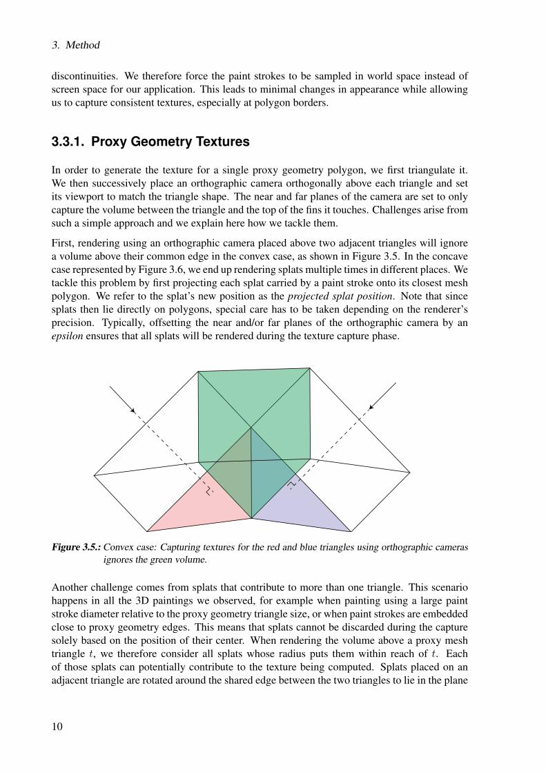
First, rendering using an orthographic camera placed above two adjacent triangles will ignorea volume above their common edge in the convex case, as shown in Figure 3.5. In the concavecase represented by Figure 3.6, we end up rendering splats multiple times in different places. Wetackle this problem by first projecting each splat carried by a paint stroke onto its closest meshpolygon. We refer to the splat’s new position as the projected splat position. Note that sincesplats then lie directly on polygons, special care has to be taken depending on the renderer’sprecision. Typically, offsetting the near and/or far planes of the orthographic camera by anepsilon ensures that all splats will be rendered during the texture capture phase.
Figure 3.5.: Convex case: Capturing textures for the red and blue triangles using orthographic camerasignores the green volume.
Another challenge comes from splats that contribute to more than one triangle. This scenariohappens in all the 3D paintings we observed, for example when painting using a large paintstroke diameter relative to the proxy geometry triangle size, or when paint strokes are embeddedclose to proxy geometry edges. This means that splats cannot be discarded during the capturesolely based on the position of their center. When rendering the volume above a proxy meshtriangle t, we therefore consider all splats whose radius puts them within reach of t. Eachof those splats can potentially contribute to the texture being computed. Splats placed on anadjacent triangle are rotated around the shared edge between the two triangles to lie in the plane
10

3.3. Capturing Fin Textures
Figure 3.6.: Concave case: Splats located in the green volume are considered twice, when capturingtextures. Once for the red and once for blue triangle and do therefore get duplicated.
defined by t. Figure 3.7 shows the difference of rotating a splat in its correct position ratherthan projecting it onto the plane defined by t. For more distant splats, we use the shortest pathfrom the splat’s projected position to the current triangle t and execute a series of such rotationsalong the edges that connect the triangles of the path, which corresponds to a “wrapping” of thesplat around the mesh.
When computing the texture for a specific triangle t, several splats in its vicinity are projectedonto t. When rendering using an orthographic camera placed above t, the splats are therefore atan equal depth from the camera, although their original positions would exhibit a depth order.Moreover, splats on adjacent triangles are seen at inconsistent depths from different cameras,as shown in Figure 3.8. In order to render the splats onto the texture with consistent depthinformation, we therefore sort them based on the distance between their original position andthe proxy mesh. This ensures a consistent depth ordering of the splats even across triangleborders. Note that for splats having exactly the same distance to the proxy geometry, we renderthe most recently painted stroke last, inspired by OverCoat [SSGS11].
Finally, since the orientation of splats in OverCoat is defined in screen space, viewing paintstrokes from cameras with different up vectors causes inconsistencies in the rendered splat ori-entations, as seen in Figure 3.9 (a). In general it is not possible to assign a continuous orientationacross a mesh without singularities, not even on simple meshes such as topological spheres, asstated by the Poincaré-Hopf theorem. In our case however, we obtain satisfying results simplyby assigning a global orientation to all triangles. We compute that global orientation by project-ing a single arbitrary vector onto each face. For faces where such a projection does not exist,we propagate the direction using the neighboring faces’ triangles. Figure 3.9 (b) shows theinfluence of using such corrected orientations. While one could envision defining a consistentorientation for every stroke individually, we found that our method provided good results andwas comfortable to implement.
11

3. Method
(a) Projecting splats (b) Rotating splats
Figure 3.7.: Simply projecting the splats on the target plane as in (a) leads to discontinuities in thetextures. Using rotations solves that problem as shown in (b).
Figure 3.8.: The two cameras assign the splats an inverted depth order when relying on the camera spacez-position.
12

3.3. Capturing Fin Textures
(a) Incorrect orientation (b) Fixed orientation
Figure 3.9.: Dealing with the splats’ orientation is necessary when rendering small parts of the sceneto generate textures. Discontinuities arise at the polygon borders if the camera orientationchanges.
3.3.2. Fin Textures
Fins are represented as quads and may not be planar. If we triangulate each fin and capture thetextures for each triangle separately, special care will have to be taken to avoid discontinuitiesbetween the obtained textures, in a similar fashion as the method described for the proxy geom-etry texture. However, in most cases fin quads are not strongly distorted. We therefore simplifythe texture capture by using one stroke rendering pass for each fin. We place the camera so thatit faces the lowest triangle orthogonally. Since the lowest triangle shares an edge with the proxygeometry, we can assume that it is less dependent on the fin deformation.
In a similar fashion to the proxy geometry texture capture, the near and far planes of the cameraare adjusted to cover the complete volume spanned by the proxy mesh triangle and its connectedfins. Similar to the ignored volume depicted in Figure 3.5, rendering the volume spanned byfins and cropping it onto a fin quad will ignore some splats. In general, fixing this issue byprojecting splats as described above introduces unpleasing perspective distortions, and the bestway to remove such artifacts is to modify the input mesh to be locally smoother.
Since the view direction can change dramatically from one fin quad to the next, discontinuitiesbetween neighboring fins cannot be avoided. We however propose a solution consisting incapturing each fin texture several times, while interpolating the camera position from a finto the next. We generate the final fin texture by concatenating strips of the multiple generatedtextures. Figure 3.10 shows how this method helps remove discontinuities between neighboringfin textures.
13

3. Method
(a) No interpolation (b) Smooth transition due to interpolation
Figure 3.10.: Interpolating the view direction helps to reduces hard changes in the fin textures.
3.4. Fin Texture Rendering
To render our approximation scenes, we apply at each frame a back-to-front sorting on all thepolygons and use per-fragment alpha blending to achieve visually correct results with our semi-transparent textures. While the proxy geometry is always rendered, fin textures should onlybe visible when their normal is close to orthogonal with the camera plane. Existing methodssuch as [LPFH01] blend whole fin quads in and out at once, which provides satisfying resultswhen used to render noisy structures like fur. However, in our context, having a fin blended inwhile its neighbors are not visible creates discontinuities, and makes the fin structure obviousto an observer. Since our goal is to give the impression that a 3D painting is being rendered inreal-time, we fade fin textures in and out per fragment, using a normal continuously interpolatedacross fin polygons.
Contrary to manifold meshes, interpolated normals across fins are not straightforward to definefor fin meshes. We therefore add an additional step to our workflow prior to rendering, thatcomputes proper vertex normals for fin meshes.
3.4.1. Fin Mesh Vertex Normal Interpolation
When rendering fins, we want to use a per-fragment normal direction for blending. That normaldirection should continuously transition from a fin to its next visible neighboring fins, to avoiddiscontinuities in the fin mesh rendering. While defining a continuous normal direction on amanifold mesh can be obtained by interpolating vertex normals across faces, the concept of a“neighboring fin” is not well defined in our case. We observed that when viewing a fin meshfrom an arbitrary angle, fins that are visible and appear to be neighbors are fins that make aclose to flat angle with each other.
We therefore conduct an additional processing step on our fin mesh, that needs to run onlyonce after the fin mesh generation. During that processing step, we assign to each fin its bestneighboring fin. Since each fin quad is based on a proxy mesh edge, two fin quads are as goodneighbors as their respective edges on the mesh make an flat angle. Our neighbor assignment isfairly simple: to each mesh edge, we first find the pair of its best neighboring unmarked edgesat its two ends, while discarding pairs of neighbors making a too sharp angle (we chose π/2 asan angular threshold for discarding). Once all pairs are listed, we define two edges as neighborsif they listed each other as their best neighbor, and we mark them. We then iterate until no newmatching is found. Finally, edges left unassigned are paired to their best neighbor, even if thatone is already marked.
14
3.4. Fin Texture Rendering
(a) Fin mesh with face normals (b) Adjusted fin mesh vertex normals
Figure 3.11.: Using the fin mesh’s face normals for the fading results in harsh discontinuities as shown inthe left figure. Calculating the interpolated vertex normals on the fin mesh helps to obtainsmooth transitions on the fins.
The neighboring information on the edges is transferred to the fins they support, and this in-formation on fin continuity lets us render fin meshes without discontinuities, as exhibited inFigure 3.11. In some cases, a fin does not admit a valid neighbor, due to the proxy geometrynot providing the corresponding edge with neighbors making a valid (over π/2) angle. This cancreate artifacts where a sole fin is rendered on the silhouette of a mesh. Using proxy geometrywith a consistent edge flow helps avoiding these issues.
15

3. Method
16
4Results
All the results shown in this master thesis are rendered in Unity [Uni15] using our custom Unitysurface shader for blending polygons in and out, as well as our back-to-front polygon sortingimplementation. Besides the rendered images in section 4.3.2. The supplemental video, createdduring the thesis, shows side by side comparisons of OverCoat paintings with the output ofour method, as well as live game sequences, that prove that our implementation can be usedconveniently in commodity game engines such as Unity. The output of our method can easilybe integrated with other special effects, as is demonstrated with the smearing and stretchingeffects shown in the video.Prior to showing the results in section 4.3, we present the obtained frame rate for our renderedscenes in section 4.1 and explain the offline approximation running duration in section 4.2.
4.1. Frame Rate
Table 4.1 shows the frame rate obtained when rendering different scenes using OverCoat, aswell as rendering the fin-texture approximations using our method in Unity. Our measurementswere taken running Unity on an Intel Core i7 2.80 GHz, with 12 GB of RAM and an NVIDIAGeForce GTX 580. The frame rate of the approximated scenes is mostly dependent on thenumber of triangles of the input geometry. Our triangle sorting script uses a fast linear-timebucket sort, and most of the rendering time in Unity is spent accessing the mesh data using theUnity API, and writing it back once sorted. Note that for static game objects, the mesh vertexpositions do not change and the mesh data does not need to be read at every frame. Since thebucket sort does not guarantee the absolute correct order of triangles, flickering artifacts canappear if the number of buckets is chosen to be too low. Therefore, we added to our sortingalgorithm the possibility to adapt the number of buckets used. In our tests, 1000 buckets wereusually enough to avoid popping artifacts. The FPS table shows that our approximations can berendered with a substantial speedup of one to two orders of magnitude compared to the originalOverCoat scenes, making them suitable for real-time applications such as games.
17

4. Results
Scene OverCoat FPS Unity FPS OverCoat Splats Unity Triangles
Cat 4.2 165 196468 18214
Magicans 0.7 55 1469633 49790
Panda 12.5 190 60992 16204
Bee 1.3 125 861114 23604
UFO X 72 417215 27122
Van Gogh 1.4 180 527143 16205
Dog 1.5 120 677355 28231
Table 4.1.: Comparison of frame rates when rendering paintings and their fin-texture approximations.Note that there is no value for the OverCoat FPS field of the UFO since that character isassembled in Unity from five independent OverCoat scenes. Images of all the listed scenesare shown in section 4.3.2
18

4.2. Offline Approximation Time
4.2. Offline Approximation Time
The running time of the offline algorithm linearly depends on the number of triangles of theproxy mesh. Without fin interpolation, for each triangle L + 3 scene renderings are necessary,where L is the number of layers used and 3 is the number of fins per triangle. The secondimportant factor is the rendering time for the scene. We render a lot of images that only showa small part of the scene. Therefore we calculate the bounding box of each stroke and use itto skip strokes efficiently when they are not intersecting the rendered volume. The boundingboxes provide a huge speedup which allows regular scenes, like the ones referred to in table 4.1,to be approximated in ten to twenty minutes. Using many fin view direction interpolation stepscan increase the approximation running time up to one or two hours, but are not necessary ingeneral to achieve good results in terms of quality.
4.3. Rendering Quality
In this section we first review the results achieved by our method. We then compare our resultsin section 4.3.3 with the results achieved by the method described in [Bra]. More results by ourmethod can be viewed in the appendix in section A.2.
4.3.1. Results Review
The rendered approximations are a satisfying reproduction of the original 3D paintings. Wenoticed that input meshes modeled as quad meshes, even if they are then triangulated, achieve ingeneral better results than models of arbitrary mesh topology. Indeed, they exhibit a consistentedge flow, with few sharp angles between adjacent mesh edges. The fins created from suchedges have a similar normal to their neighboring fins, which is beneficial for our results asexplained in section 3.4.
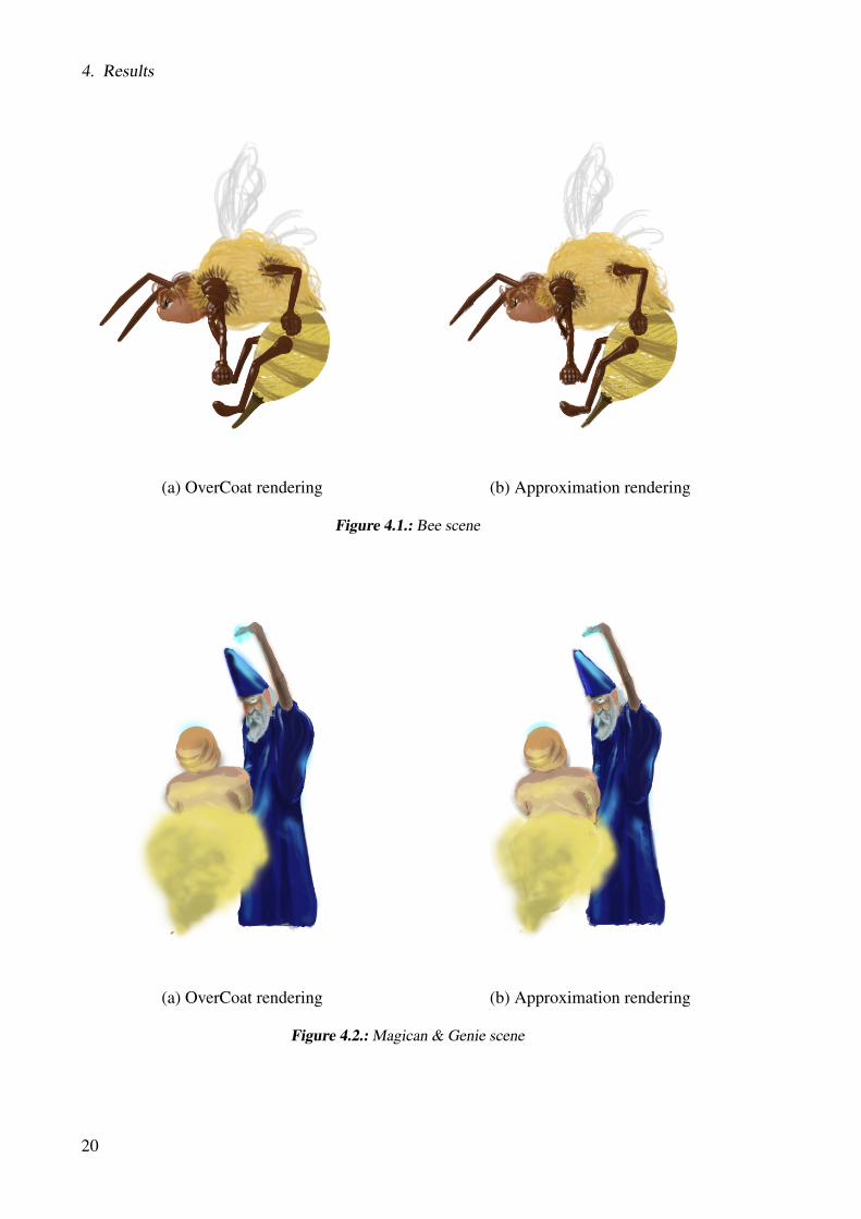
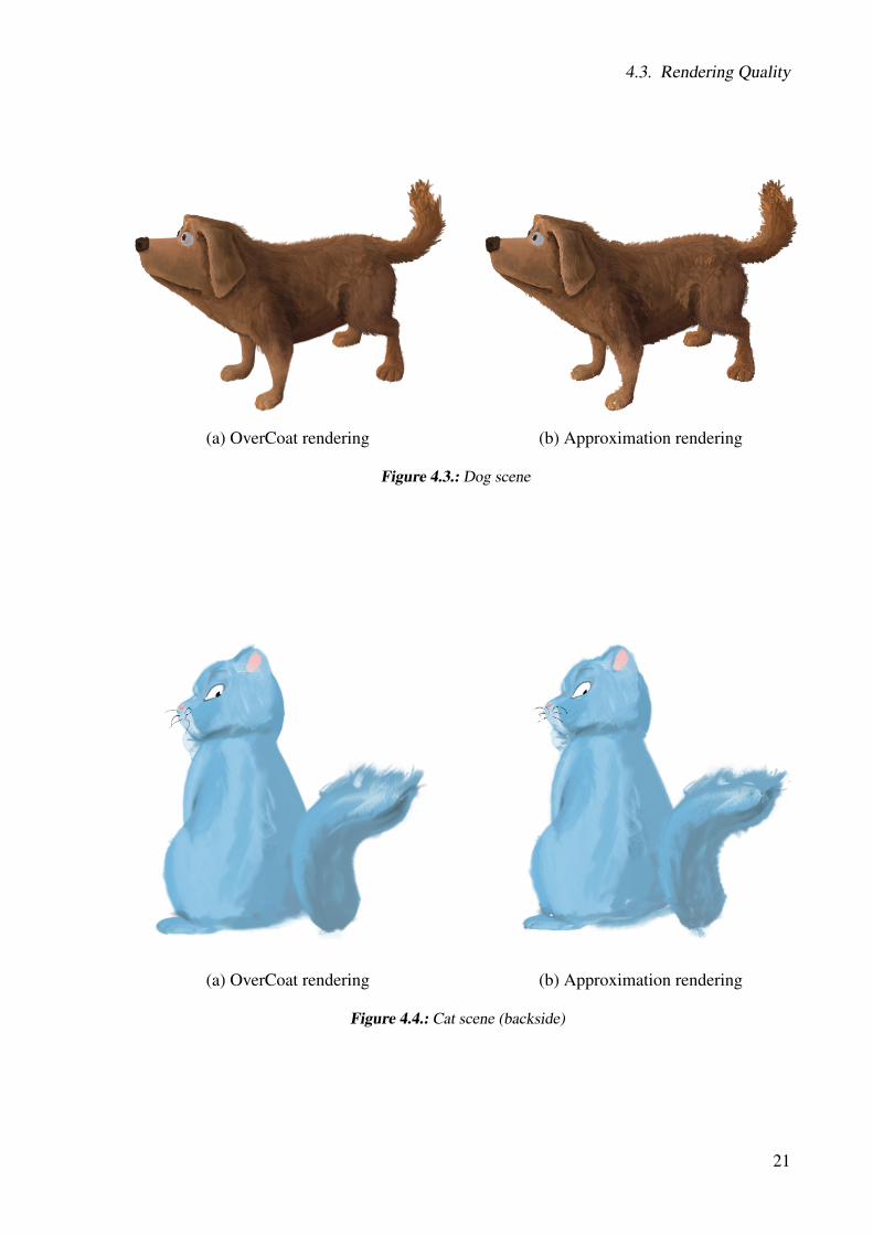
Contrary to existing shell texture methods such as [LPFH01], we only used a proxy mesh andfins, and did not define layered textures. We observed that in most cases our method achievessatisfying results, while benefiting from a lower polygon count. A low polygon count naturallyincreases the frame rate during rendering, but also helped us target real-time rendering using theUnity game engine. Indeed, that engine enforces a maximum of 65536 triangles or vertices ina single mesh, and that limit can be quickly reached by our algorithm when using many layersor complex input meshes. Nonetheless, a single fin quad per edge was sufficient to render thefluffy bee body, the yellow smoke around the genie, or the dog’s tail presented in Figure 4.1,4.2 and 4.3, respectively.
19
4. Results
(a) OverCoat rendering (b) Approximation rendering
Figure 4.1.: Bee scene
(a) OverCoat rendering (b) Approximation rendering
Figure 4.2.: Magican & Genie scene
20
4.3. Rendering Quality
(a) OverCoat rendering (b) Approximation rendering
Figure 4.3.: Dog scene
(a) OverCoat rendering (b) Approximation rendering
Figure 4.4.: Cat scene (backside)
21
4. Results
(a) OverCoat rendering (b) Approximation rendering
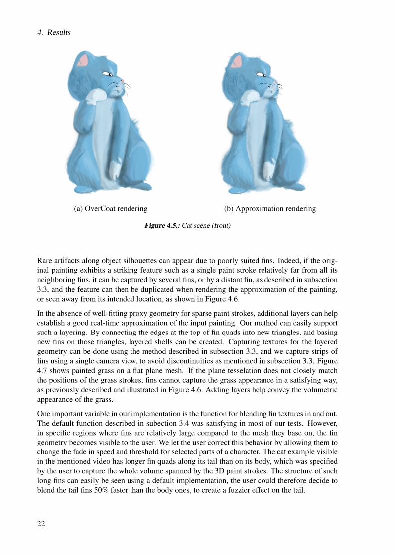
Figure 4.5.: Cat scene (front)
Rare artifacts along object silhouettes can appear due to poorly suited fins. Indeed, if the orig-inal painting exhibits a striking feature such as a single paint stroke relatively far from all itsneighboring fins, it can be captured by several fins, or by a distant fin, as described in subsection3.3, and the feature can then be duplicated when rendering the approximation of the painting,or seen away from its intended location, as shown in Figure 4.6.
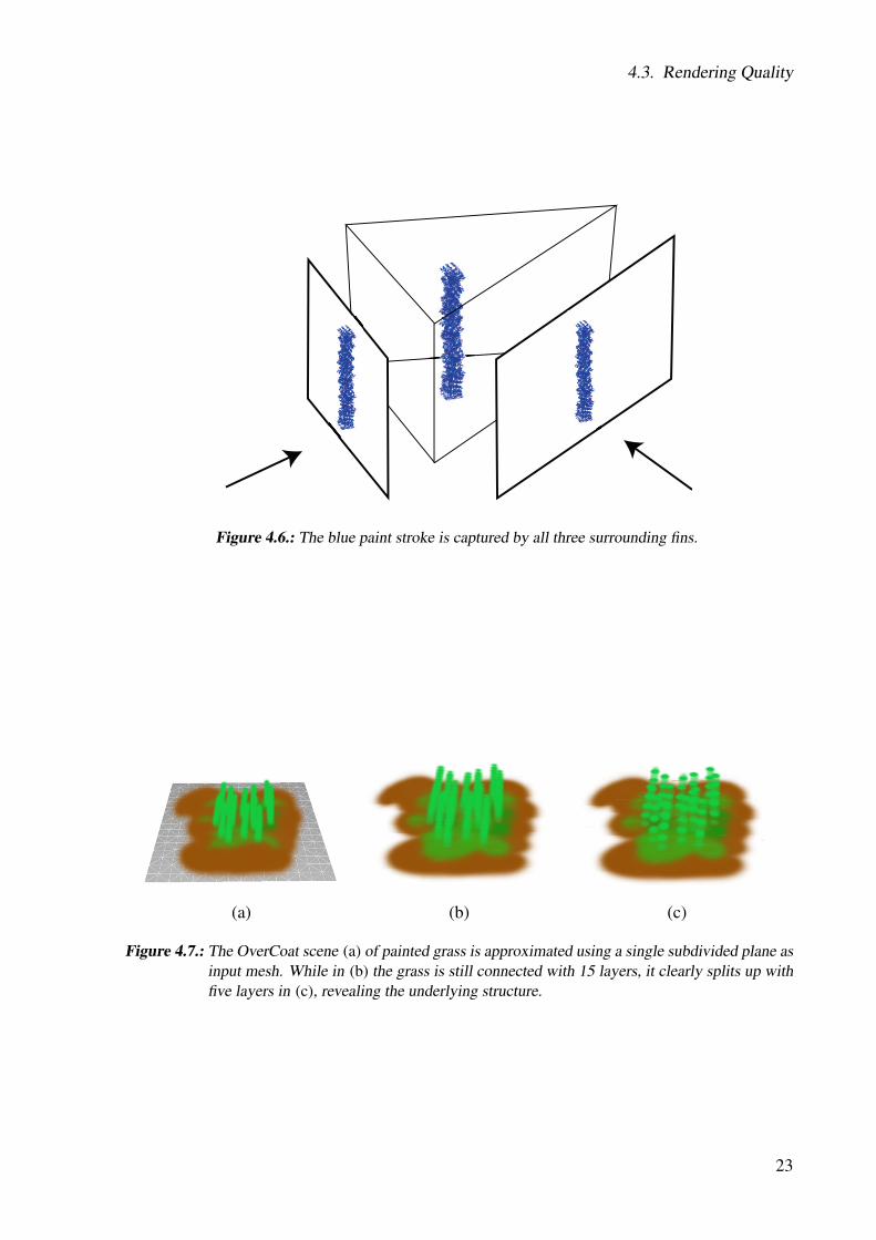
In the absence of well-fitting proxy geometry for sparse paint strokes, additional layers can helpestablish a good real-time approximation of the input painting. Our method can easily supportsuch a layering. By connecting the edges at the top of fin quads into new triangles, and basingnew fins on those triangles, layered shells can be created. Capturing textures for the layeredgeometry can be done using the method described in subsection 3.3, and we capture strips offins using a single camera view, to avoid discontinuities as mentioned in subsection 3.3. Figure4.7 shows painted grass on a flat plane mesh. If the plane tesselation does not closely matchthe positions of the grass strokes, fins cannot capture the grass appearance in a satisfying way,as previously described and illustrated in Figure 4.6. Adding layers help convey the volumetricappearance of the grass.
One important variable in our implementation is the function for blending fin textures in and out.The default function described in subection 3.4 was satisfying in most of our tests. However,in specific regions where fins are relatively large compared to the mesh they base on, the fingeometry becomes visible to the user. We let the user correct this behavior by allowing them tochange the fade in speed and threshold for selected parts of a character. The cat example visiblein the mentioned video has longer fin quads along its tail than on its body, which was specifiedby the user to capture the whole volume spanned by the 3D paint strokes. The structure of suchlong fins can easily be seen using a default implementation, the user could therefore decide toblend the tail fins 50% faster than the body ones, to create a fuzzier effect on the tail.
22
4.3. Rendering Quality
Figure 4.6.: The blue paint stroke is captured by all three surrounding fins.
(a) (b) (c)
Figure 4.7.: The OverCoat scene (a) of painted grass is approximated using a single subdivided plane asinput mesh. While in (b) the grass is still connected with 15 layers, it clearly splits up withfive layers in (c), revealing the underlying structure.
23
4. Results
4.3.2. Game Scenes
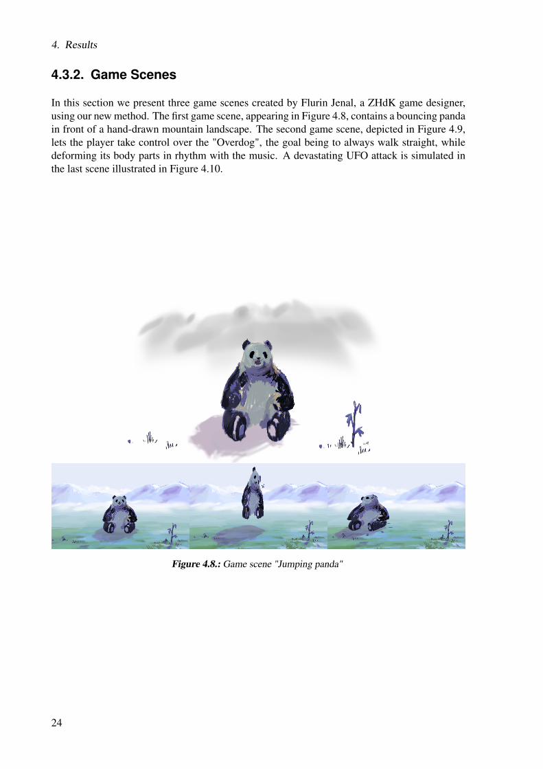
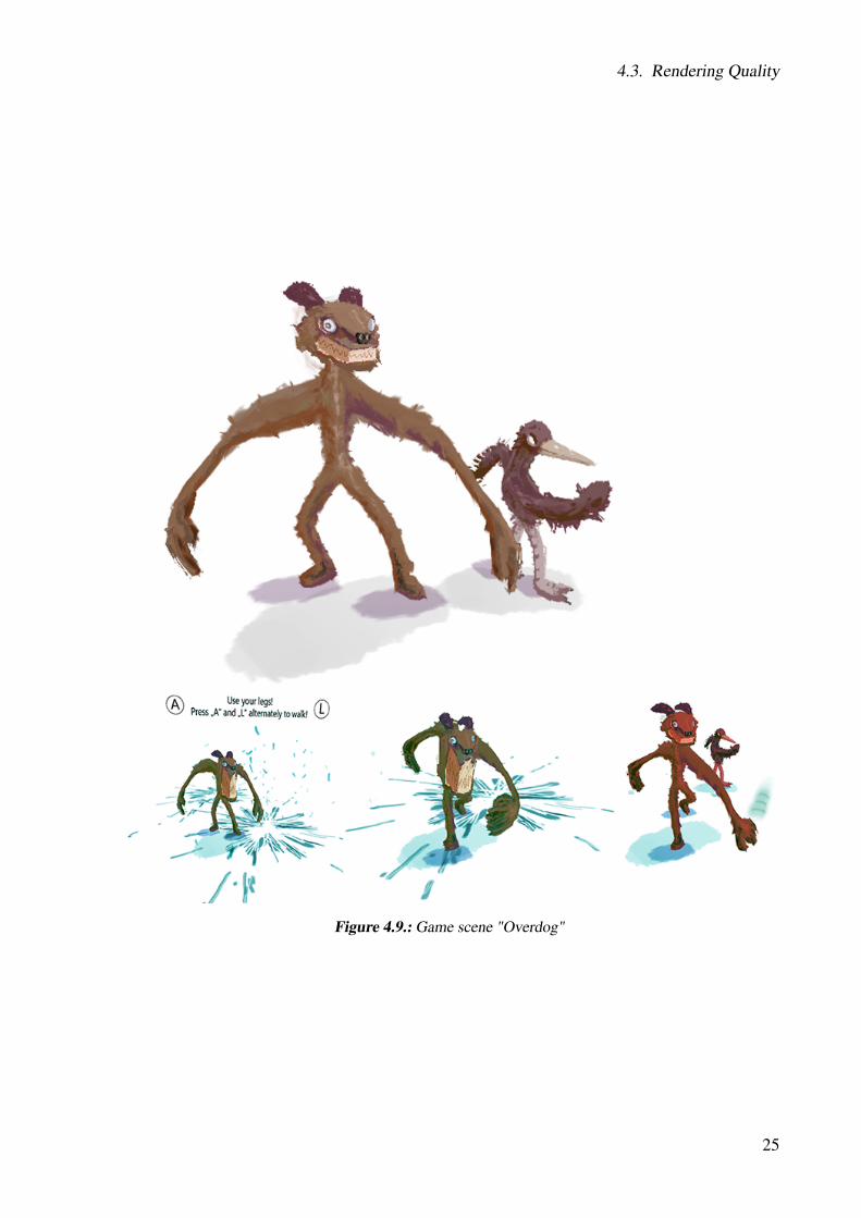
In this section we present three game scenes created by Flurin Jenal, a ZHdK game designer,using our new method. The first game scene, appearing in Figure 4.8, contains a bouncing pandain front of a hand-drawn mountain landscape. The second game scene, depicted in Figure 4.9,lets the player take control over the "Overdog", the goal being to always walk straight, whiledeforming its body parts in rhythm with the music. A devastating UFO attack is simulated inthe last scene illustrated in Figure 4.10.
Figure 4.8.: Game scene "Jumping panda"
24
4.3. Rendering Quality
Figure 4.9.: Game scene "Overdog"
25

4. Results
Figure 4.10.: Game scene "Attacking UFO"
26
4.3. Rendering Quality
4.3.3. Comparison with Kimono Approximation
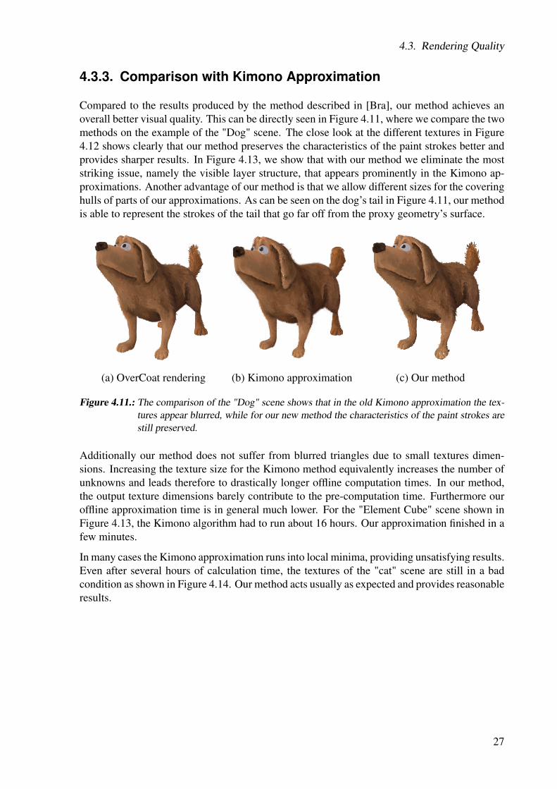
Compared to the results produced by the method described in [Bra], our method achieves anoverall better visual quality. This can be directly seen in Figure 4.11, where we compare the twomethods on the example of the "Dog" scene. The close look at the different textures in Figure4.12 shows clearly that our method preserves the characteristics of the paint strokes better andprovides sharper results. In Figure 4.13, we show that with our method we eliminate the moststriking issue, namely the visible layer structure, that appears prominently in the Kimono ap-proximations. Another advantage of our method is that we allow different sizes for the coveringhulls of parts of our approximations. As can be seen on the dog’s tail in Figure 4.11, our methodis able to represent the strokes of the tail that go far off from the proxy geometry’s surface.
(a) OverCoat rendering (b) Kimono approximation (c) Our method
Figure 4.11.: The comparison of the "Dog" scene shows that in the old Kimono approximation the tex-tures appear blurred, while for our new method the characteristics of the paint strokes arestill preserved.
Additionally our method does not suffer from blurred triangles due to small textures dimen-sions. Increasing the texture size for the Kimono method equivalently increases the number ofunknowns and leads therefore to drastically longer offline computation times. In our method,the output texture dimensions barely contribute to the pre-computation time. Furthermore ouroffline approximation time is in general much lower. For the "Element Cube" scene shown inFigure 4.13, the Kimono algorithm had to run about 16 hours. Our approximation finished in afew minutes.
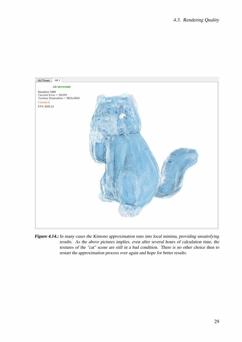
In many cases the Kimono approximation runs into local minima, providing unsatisfying results.Even after several hours of calculation time, the textures of the "cat" scene are still in a badcondition as shown in Figure 4.14. Our method acts usually as expected and provides reasonableresults.
27
4. Results
(a) Kimono approximation (b) Our method
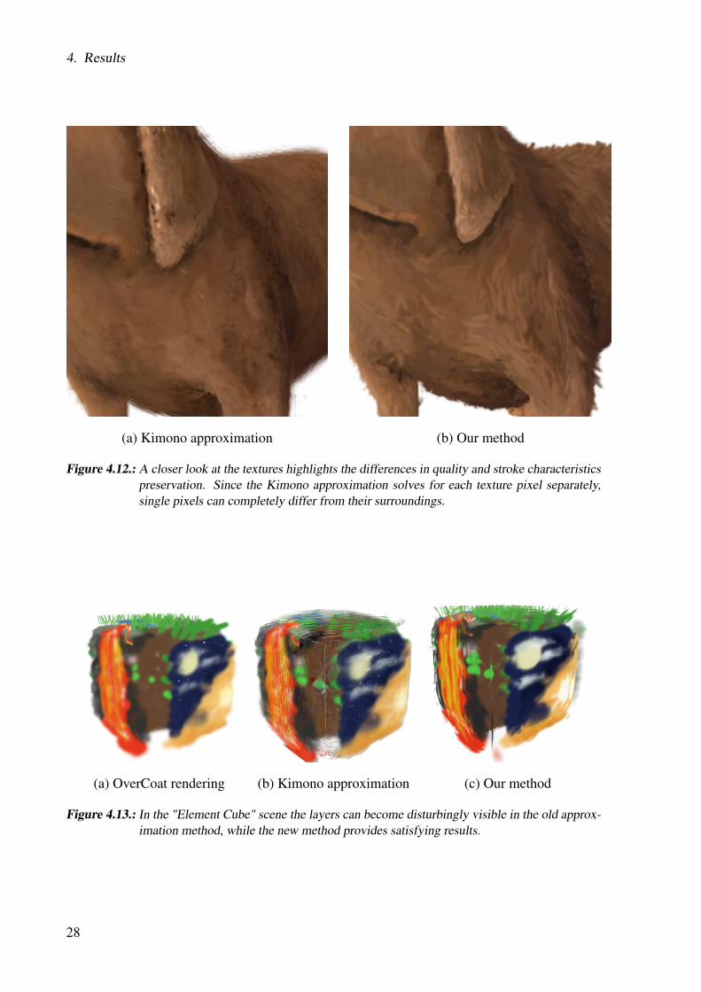
Figure 4.12.: A closer look at the textures highlights the differences in quality and stroke characteristicspreservation. Since the Kimono approximation solves for each texture pixel separately,single pixels can completely differ from their surroundings.
(a) OverCoat rendering (b) Kimono approximation (c) Our method
Figure 4.13.: In the "Element Cube" scene the layers can become disturbingly visible in the old approx-imation method, while the new method provides satisfying results.
28
4.3. Rendering Quality
Figure 4.14.: In many cases the Kimono approximation runs into local minima, providing unsatisfyingresults. As the above pictures implies, even after several hours of calculation time, thetextures of the "cat" scene are still in a bad condition. There is no other choice then torestart the approximation process over again and hope for better results.
29
4. Results
30

5Limitations and Future Work
Our results reveal the limitations of our method and indicate several possible directions forfuture work.
First, as previously stated, using complex meshes or high numbers of shell layers can result inpolygon counts that overshoot the Unity limitation. A possible solution to bypass this limitationis to split complex objects into several independent ones. In our current implementation, theback-to-front sorting of polygons is performed per object. Splitting paintings into several gameobjects would require adapting our sorting algorithm to be performed globally. While a naiveimplementation would slow down the rendering time, adding a collision detection pass acrossgame objects would help optimize the polygon sorting to remain local across colliding objects.
Parts of the shell distortion could be circumvented by a better construction algorithm for theoffset mesh. Although more elaborate algorithms for creating smooth offset meshes exist, tothe best of our knowledge, no existing solution focuses on avoiding distorted shells. A possiblesolution could be to formulate the offset mesh construction as an optimization problem thatwould solve for the offset vector from each vertex on the proxy geometry mesh while penalizingthe distortion of the shells. Additional energy terms could be used to avoid the self-intersectionof shells or to force fin quads to be planar, making the capture of their texture more accurate.
An interesting way to further improve the appearance of the fins would be to create offsetmeshes with independent topology. Thus, parts of a mesh with a particularly high curvaturecould be subdivided as they are offset, while highly concave parts could be decimated as theyare offset. In such a process, self intersections could be avoided and the number of polygons inoffset meshes would be locally more suited to our application.
Taking this paradigm to the next level, one could try to circumvent the dependency of the resultson adequate input geometry by designing an algorithm that crafts a completely new geometrydepending on the positions of the scene’s paint strokes. This adapted geometry could possiblyachieve more accurate results and could alleviate the need for the artist to construct the precisegeometry beforehand. One could still allow to modify the generated geometry manually, so thatthe artist keeps direct control and influence via the input mesh.
To the best of our knowledge, no real-time lighting solution for 3D paintings such as thosepresented in [SSGS11] has been proposed. Indeed, 3D paint strokes rendered in screen spacedo not admit an exact volumetric description, and cannot be represented as a manifold. Adaptingexisting shading algorithms to such paintings is therefore an ill-defined problem. In our context,the shell mesh and fins approximating a painting have an exact 3D representation and could intheory be lit using traditional shading principles. Special care would have to be taken for fins asthey should not be lit according to their normal, but according to the normal of the mesh layerto which they are attached. Whether an accurate 3D shading would be aesthetically pleasingwhen used on stylized structures such as our paintings remains to be explored.
31

5. Limitations and Future Work
32

6Conclusion
We presented a novel algorithm that uses precomputation to generate fin-texture approximationsof complex 3D paintings that preserve the artist’s original design. The approximations can berendered in real-time and combine layer textures (on and around the proxy geometry) togetherwith fin textures that are orthogonal to the proxy geometry and fade in using a per-fragmentinterpolated vertex normal value when facing the camera. Our results show that layer textureson the proxy geometry reduce 3D paintings to textured meshes which exhibit sharp edges onscreen, while the generated fin textures help convey the original painterly style in real-timeby covering the sharp borders of the layer textures. While our composited results provide asatisfying depiction of the input 3D paintings, our experience helped us identify limitations ofcapturing and using textures from shells constructed by offset mesh generation.
33

6. Conclusion
34
AAppendix
A.1. Workflow Documentation
This section describes how to use the integrated interface in OverCoat to generate an approxi-mation from a painted scene. Moreover, it explains how to correctly import the approximationin Unity and how to apply possible modifications to alter its appearance.
A.1.1. OverCoat Interface
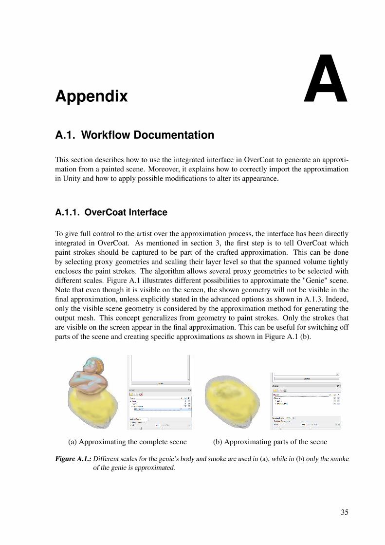
To give full control to the artist over the approximation process, the interface has been directlyintegrated in OverCoat. As mentioned in section 3, the first step is to tell OverCoat whichpaint strokes should be captured to be part of the crafted approximation. This can be doneby selecting proxy geometries and scaling their layer level so that the spanned volume tightlyencloses the paint strokes. The algorithm allows several proxy geometries to be selected withdifferent scales. Figure A.1 illustrates different possibilities to approximate the "Genie" scene.Note that even though it is visible on the screen, the shown geometry will not be visible in thefinal approximation, unless explicitly stated in the advanced options as shown in A.1.3. Indeed,only the visible scene geometry is considered by the approximation method for generating theoutput mesh. This concept generalizes from geometry to paint strokes. Only the strokes thatare visible on the screen appear in the final approximation. This can be useful for switching offparts of the scene and creating specific approximations as shown in Figure A.1 (b).
(a) Approximating the complete scene (b) Approximating parts of the scene
Figure A.1.: Different scales for the genie’s body and smoke are used in (a), while in (b) only the smokeof the genie is approximated.
35
A. Appendix
A.1.2. Approximation Interface
Once a scene is ready to be approximated, the approximation interface, shown in Fig. A.2), canbe found under Tools -> Show Approximation Window or alternatively by pressing Ctrl+A. Ingeneral, the advanced options do not need to be changed and are only intended for experiencedusers or for very specific purposes. Detailed information about each setting is provided below:
Select FolderSpecifies the directory where the files will be created.
Output file nameSpecifies the base name of the created files.
Number of layersDefines how many mesh layers are created.
Output texture sizeDefines the pixel-dimensions of the created textures. Possible options are 512, 1024, 2048 and4096 pixels. Note that 2048 is the recommended maximum since the current Unity version doesnot seem to use the 4096 sized texture correctly. In our tests, it appeared that Unity downscalesthe texture which results in the same artifacts as described in A.1.4 with activated mip maps.
Texture qualityDefines the size of the images taken by the algorithm when rendering the scene. Smaller valuesreduce the time needed for the algorithm to terminate but can reduce the quality of the finaloutput textures.
Fin add top/bottom spaceWith these parameters, additional space can be given to the fins at the top and bottom.
A.1.3. Advanced Options
Interpolate view directionThis parameter allows the user to specify that the algorithm should perform additional inter-polation steps as described in section 3.3 and as appears in Figure 3.10. The parameter valuerepresents the maximum non-interpolated change in the angle of the viewing direction from afin to its neighbors.
Show strokes as world space sampledEnsures that all strokes are world-space-sampled to avoid inconsistent splat positions.
Project splats on layersThis option tells the algorithm to project all splats on the closest layer to avoid missing or du-plicated splats.
36

A.1. Workflow Documentation
Figure A.2.: Approximation interface integrated in Overcoat
Uniform splat orientationLets the algorithm try to compute a uniform orientation for the splats across the geometry. Thisoption is only noticeable if the scene contains splats which are orientation dependent.
Horizontal fin view directionWhen activated, the view direction is manipulated to be parallel to the base triangle, when ren-dering images for the fins.
Speed up with bounding boxesThe algorithm computes bounding boxes for the strokes, which are then used to easily skipsplats that can not contribute to the rendered volume. This option drastically decreases theoverall approximation time in general.
Only keep fins of quad edgesThe algorithm tries to quadrangulate the given input meshes. For each found quad, the inneredge is then excluded from the final output mesh.
37
A. Appendix
Keep to combine with next approximationThis option tells the algorithm to keep the data from the current approximation and to add itwhen creating the next approximation. This way, multiple scenes can be loaded and approxi-mated independently but are still combined in the output textures and mesh.
A.1.4. Unity Import
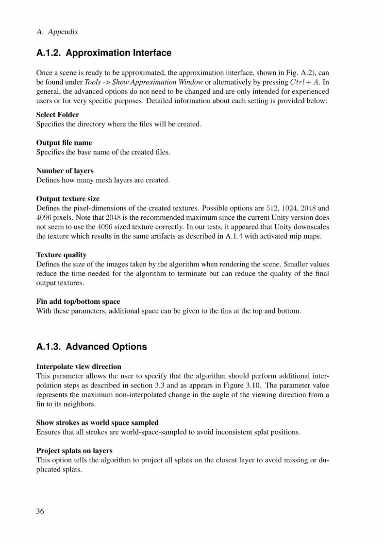
To import the approximation in Unity, one simply adds the object file as well as the two texturesto Unity. To ensure correct appearance, the settings of the textures need to be modified. Thetexture type should be changed manually from Textured to Advanced. This allows to see andmodify more options concerning the texture in Unity. The flag "Generate Mip Maps" shouldbe switched to the unchecked status, since the automatic mip map generation leads to problemswith the semitransparent textures. From the way our layer and fin textures are structured, ar-tifacts appear especially at the in general transparent fin ends, since the transparent pixels getmerged with non-transparent pixels from the fin located above in the texture. Figure A.3 showsthe slightly visual artifacts that arise when mip maps are switched on.
(a) Using mip maps (b) Mip maps off
Figure A.3.: Different Unity texture settings illustrated on the blue cat. Artifacts appear at the fins’ endin (a). No such artifacts are visible in (b).
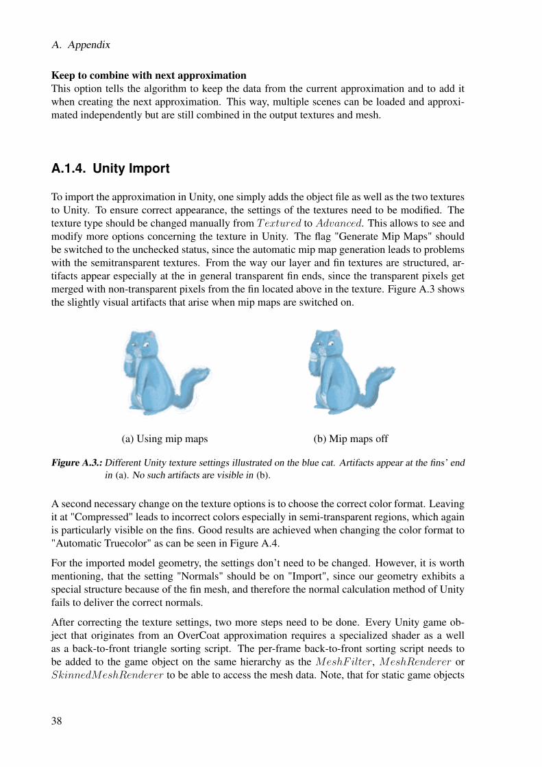
A second necessary change on the texture options is to choose the correct color format. Leavingit at "Compressed" leads to incorrect colors especially in semi-transparent regions, which againis particularly visible on the fins. Good results are achieved when changing the color format to"Automatic Truecolor" as can be seen in Figure A.4.
For the imported model geometry, the settings don’t need to be changed. However, it is worthmentioning, that the setting "Normals" should be on "Import", since our geometry exhibits aspecial structure because of the fin mesh, and therefore the normal calculation method of Unityfails to deliver the correct normals.
After correcting the texture settings, two more steps need to be done. Every Unity game ob-ject that originates from an OverCoat approximation requires a specialized shader as a wellas a back-to-front triangle sorting script. The per-frame back-to-front sorting script needs tobe added to the game object on the same hierarchy as the MeshFilter, MeshRenderer orSkinnedMeshRenderer to be able to access the mesh data. Note, that for static game objects
38
A.1. Workflow Documentation
(a) Compressed - artifacts appear (b) Truecolor - no color artifacts
Figure A.4.: Different Unity texture formats illustrated on the blue cat’s tail.
that can only be seen from a certain view direction, the back-to-front sorting script can be runonly once and then be removed or deactivated to save performance. In Unity’s inspector, thescript provides two modifiable parameters. The first one is the number of buckets to use for thebucket sort. The default value, as seen in Figure A.5 (a), is 1000, which generally is sufficient.However, it should be increased if flickering or wrongly sorted triangles appear. The second pa-rameter specifies if the variable vertex positions of an animated character should be calculatedby the GPU or the CPU. On the one hand, having the work done by the CPU instead of the GPUincreases the calculation time of the script. On the other hand, retrieving the vertex positionsof a skinned mesh from the GPU using the Unity API is faster, but allocates a new vertex arrayevery frame. This creates a considerable amount of garbage from which performance spikesarise, that can be perceived as periodical lags, when the garbage collector becomes active.
Unlike the KimonoRenderer, the KimonoShader script offers several tunable parameters as Fig-ure A.5 (b) suggests. In the first two texture slots, the model’s layer and fin texture should bereferenced. The sliders for the layers and fins visibility allow to assign each of them a separateopacity.
Modifications
Additional functionality can be easily integrated into the shader script. For example, an artistmight want to apply a different color to the fin textures to intensify their appearance or to havethem look similar to a Toon shader. Figure A.6 shows the cat scene rendered with such amodified shader.
An alternative way to alter the appearance of an approximation is to directly modify the layerand fin textures with an external tool such as Photoshop. Figure A.7 shows the UFO sceneonce with the original textures and once with adjusted colors. While this may seem straightforward, care has to be taken because of the special pre-multiplied image format of the textures.For example in Photoshop, when simply deleting parts of the texture to make them appearcompletely transparent, the deleted parts will surprisingly appear white in Unity. The problemis that the saved color is a transparent white and not a transparent black, which is needed for the
39
A. Appendix
(a) KimonoRenderer (b) KimonoShader
Figure A.5.: The two Unity scripts that are necessary for the approximations to look correct. TheKimonoRenderer in (a) ensures a back-to-front sorting of the mesh triangles on everyframe. The KimonoShader controls the fading in and out of the fins.
Figure A.6.: As a possible example on how to extend the current shader, this cat scene uses an extendedshader with additional color option for the fins.
40
A.1. Workflow Documentation
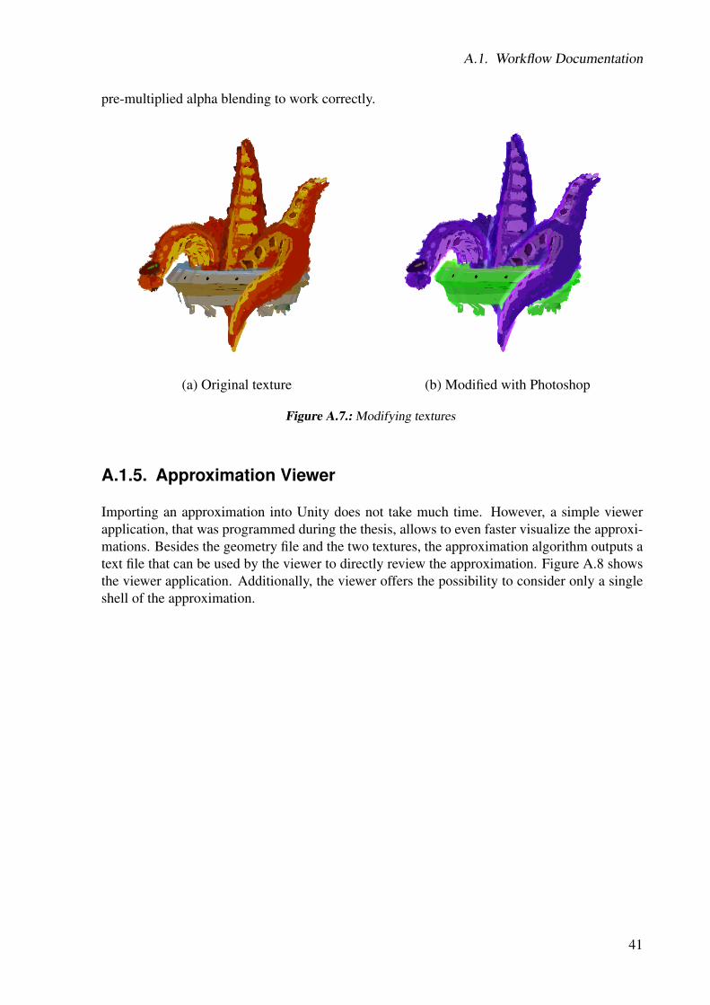
pre-multiplied alpha blending to work correctly.
(a) Original texture (b) Modified with Photoshop
Figure A.7.: Modifying textures
A.1.5. Approximation Viewer
Importing an approximation into Unity does not take much time. However, a simple viewerapplication, that was programmed during the thesis, allows to even faster visualize the approxi-mations. Besides the geometry file and the two textures, the approximation algorithm outputs atext file that can be used by the viewer to directly review the approximation. Figure A.8 showsthe viewer application. Additionally, the viewer offers the possibility to consider only a singleshell of the approximation.
41

A. Appendix
Figure A.8.: KimonoViewer
A.2. Additional Results
In this section we present further results that we did not show in section 4. Figure A.9 showsa depiction of Van Gogh and allows to directly compare the approximation with the OverCoatscene. In figure A.10, the mouse of the original OverCoat scene is added to the approximation.Additionally, shadow projectors are added to the scene to enhance the spatial impression. Infigure A.11, the panda, that is used in the "Jumping Panda" game scene, can be compared to itsoriginal OverCoat painting from the side. Last, various approximations of different scenes areshown in the Figure A.12.
42

A.2. Additional Results
(a) OverCoat rendering (b) Approximation rendering
Figure A.9.: Van Gogh scene
Figure A.10.: Cat and Mouse scene - Both images show an approximation of the original scene withadditional shadow projectors.
43

A. Appendix
(a) OverCoat rendering (b) Approximation rendering
Figure A.11.: Panda scene
(a) Ballerina scene (b) Blowfish scene (c) Skull scene
Figure A.12.: Various approximated scenes
44

Bibliography
[BBS+13] Katie Bassett, Ilya Baran, Johannes Schmid, Markus Gross, and Robert W.Sumner. Authoring and animating painterly characters. ACM Trans. Graph.,32(5):156:1–156:12, October 2013.
[BBT11] Pierre Bénard, Adrien Bousseau, and Joëlle Thollot. State-of-the-art report on tem-poral coherence for stylized animations. Computer Graphics Forum, 30(8):2367–2386, 2011.
[Bra] Manuel Braunschweiler. Real-time rendering of complex 3d paintings for novelvideo game visual style. ETH Bachelor Thesis.
[BSS+11] Ilya Baran, Johannes Schmid, Thomas Siegrist, Markus Gross, and Robert W.Sumner. Mixed-order compositing for 3d paintings. ACM Transactions on Graph-ics, 30(6), 2011.
[Cag10] David Cage. Heavy Rain. Quantic Dream, February 2010.
[Che09] Jenova Chen. Flower. Thatgamecompany, February 2009.
[CTW+04] Yanyun Chen, Xin Tong, Jiaping Wang, Stephen Lin, Baining Guo, and Heung-Yeung Shum. Shell texture functions. In ACM SIGGRAPH 2004 Papers, SIG-GRAPH ’04, pages 343–353, New York, NY, USA, 2004. ACM.
[Elb99] Gershon Elber. Interactive line art rendering of freeform surfaces. ComputerGraphics Forum, 18(3):1–12, 1999.
[GGSC98] Amy Gooch, Bruce Gooch, Peter Shirley, and Elaine Cohen. A non-photorealisticlighting model for automatic technical illustration. In Proceedings of the 25th An-nual Conference on Computer Graphics and Interactive Techniques, SIGGRAPH

Bibliography
’98, pages 447–452, New York, NY, USA, 1998. ACM.
[HGT13] Siddharth Hegde, Christos Gatzidis, and Feng Tian. Painterly rendering tech-niques: a state-of-the-art review of current approaches. Computer Animation andVirtual Worlds, 24(1):43–64, 2013.
[HJO+01] Aaron Hertzmann, Charles E. Jacobs, Nuria Oliver, Brian Curless, and David H.Salesin. Image analogies. In Proceedings of the 28th Annual Conference on Com-puter Graphics and Interactive Techniques, SIGGRAPH ’01, pages 327–340, NewYork, NY, USA, 2001. ACM.
[Kik00] Masayoshi Kikuchi. Jet Set Radio. SmileBit, June 2000.
[KK89] J. T. Kajiya and T. L. Kay. Rendering fur with three dimensional textures. InProceedings of the 16th Annual Conference on Computer Graphics and InteractiveTechniques, SIGGRAPH ’89, pages 271–280, New York, NY, USA, 1989. ACM.
[KL03] G Katanics and T Lappas. Deep canvas: integrating 3d painting and painterly ren-dering. Theory and Practice of Non-Photorealistic Graphics: Algorithms, Meth-ods, and Production Systems, 2003.
[KMM+02] Robert D. Kalnins, Lee Markosian, Barbara J. Meier, Michael A. Kowalski,Joseph C. Lee, Philip L. Davidson, Matthew Webb, John F. Hughes, and AdamFinkelstein. WYSIWYG NPR: Drawing strokes directly on 3D models. ACMTransactions on Graphics (Proc. SIGGRAPH), 21(3):755–762, July 2002.
[Len00] JeromeEdward Lengyel. Real-time fur. In Bernard Péroche and Holly Rushmeier,editors, Rendering Techniques 2000, Eurographics, pages 243–256. Springer Vi-enna, 2000.
[Lit97] Peter Litwinowicz. Processing images and video for an impressionist effect. InProceedings of the 24th Annual Conference on Computer Graphics and InteractiveTechniques, SIGGRAPH ’97, pages 407–414, New York, NY, USA, 1997. ACMPress/Addison-Wesley Publishing Co.
[LPFH01] Jerome Lengyel, Emil Praun, Adam Finkelstein, and Hugues Hoppe. Real-timefur over arbitrary surfaces. In Proceedings of the 2001 Symposium on Interactive3D Graphics, I3D ’01, pages 227–232, New York, NY, USA, 2001. ACM.
[Mei96] Barbara J. Meier. Painterly rendering for animation. In Proceedings of the 23rd An-nual Conference on Computer Graphics and Interactive Techniques, SIGGRAPH’96, pages 477–484, New York, NY, USA, 1996. ACM.
[MG02] Aditi Majumder and M. Gopi. Hardware accelerated real time charcoal render-ing. In Proceedings of the 2Nd International Symposium on Non-photorealisticAnimation and Rendering, NPAR ’02, pages 59–66, New York, NY, USA, 2002.ACM.
[MKG+97] Lee Markosian, Michael A. Kowalski, Daniel Goldstein, Samuel J. Trychin,John F. Hughes, and Lubomir D. Bourdev. Real-time nonphotorealistic render-ing. In Proceedings of the 24th Annual Conference on Computer Graphics andInteractive Techniques, SIGGRAPH ’97, pages 415–420, New York, NY, USA,
46
Bibliography
1997. ACM Press/Addison-Wesley Publishing Co.
[MN98] Alexandre Meyer and Fabrice Neyret. Interactive volumetric textures. In GeorgeDrettakis and Nelson Max, editors, Rendering Techniques Š98, Eurographics,pages 157–168. Springer Vienna, 1998.
[MO12] Chris Melissinos and Patrick O’Rourke. The Art of Video Games: From Pac-Manto Mass Effect. Welcome Books, March 2012.
[MoM12] MoMA Press. MoMA acquires 14 video games for architecture and design collec-tion. Press Release, December 2012.
[MPN+02] Wojciech Matusik, Hanspeter Pfister, Addy Ngan, Paul Beardsley, Remo Ziegler,and Leonard McMillan. Image-based 3d photography using opacity hulls. ACMTrans. Graph., 21(3):427–437, July 2002.
[Ney98] Fabrice Neyret. Modeling, animating, and rendering complex scenes using vol-umetric textures. IEEE Transactions on Visualization and Computer Graphics,4(1):55–70, January 1998.
[ODAO15] Makoto Okabe, Yoshinori Dobashi, Ken Anjyo, and Rikio Onai. Fluid volumemodeling from sparse multi-view images by appearance transfer. ACM Transac-tions on Graphics (Proc. SIGGRAPH 2015), 34(4):93:1–93:10, 2015.
[PBFJ05] Serban D. Porumbescu, Brian Budge, Louis Feng, and Kenneth I. Joy. Shell maps.In ACM SIGGRAPH 2005 Papers, SIGGRAPH ’05, pages 626–633, New York,NY, USA, 2005. ACM.
[PHWF01] Emil Praun, Hugues Hoppe, Matthew Webb, and Adam Finkelstein. Real-timehatching. In Proceedings of the 28th Annual Conference on Computer Graphicsand Interactive Techniques, SIGGRAPH ’01, pages 581–, New York, NY, USA,2001. ACM.
[Pla99] John Zuur Platten. Fear Effect. Kronos Digital Entertainment, 1999.
[SSGS11] Johannes Schmid, Martin Sebastian Senn, Markus Gross, and Robert W. Sumner.Overcoat: an implicit canvas for 3d painting. ACM Trans. Graph., 30:28:1–28:10,August 2011.
[Uni15] Unity. Unity Technologies, 2015. www.unity3d.com.
[VPM+03] Daniel Vlasic, Hanspeter Pfister, Sergey Molinov, Radek Grzeszczuk, and Woj-ciech Matusik. Opacity light fields: Interactive rendering of surface light fieldswith view-dependent opacity. In Proceedings of the 2003 Symposium on Interac-tive 3D Graphics, I3D ’03, pages 65–74, New York, NY, USA, 2003. ACM.
47

Bibliography
48


Bibliography
50