Embed Size (px)
Citation preview

Real-Time Windows Target™ 3User’s Guide

How to Contact The MathWorks
www.mathworks.com Webcomp.soft-sys.matlab Newsgroupwww.mathworks.com/contact_TS.html Technical [email protected] Product enhancement [email protected] Bug [email protected] Documentation error [email protected] Order status, license renewals, [email protected] Sales, pricing, and general information
508-647-7000 (Phone)
508-647-7001 (Fax)
The MathWorks, Inc.3 Apple Hill DriveNatick, MA 01760-2098For contact information about worldwide offices, see the MathWorks Web site.Real-Time Windows Target™ User’s Guide© COPYRIGHT 1999–2009 by The MathWorks, Inc.The software described in this document is furnished under a license agreement. The software may be usedor copied only under the terms of the license agreement. No part of this manual may be photocopied orreproduced in any form without prior written consent from The MathWorks, Inc.FEDERAL ACQUISITION: This provision applies to all acquisitions of the Program and Documentationby, for, or through the federal government of the United States. By accepting delivery of the Programor Documentation, the government hereby agrees that this software or documentation qualifies ascommercial computer software or commercial computer software documentation as such terms are usedor defined in FAR 12.212, DFARS Part 227.72, and DFARS 252.227-7014. Accordingly, the terms andconditions of this Agreement and only those rights specified in this Agreement, shall pertain to and governthe use, modification, reproduction, release, performance, display, and disclosure of the Program andDocumentation by the federal government (or other entity acquiring for or through the federal government)and shall supersede any conflicting contractual terms or conditions. If this License fails to meet thegovernment’s needs or is inconsistent in any respect with federal procurement law, the government agreesto return the Program and Documentation, unused, to The MathWorks, Inc.
Trademarks
MATLAB and Simulink are registered trademarks of The MathWorks, Inc. Seewww.mathworks.com/trademarks for a list of additional trademarks. Other product or brandnames may be trademarks or registered trademarks of their respective holders.Patents
The MathWorks products are protected by one or more U.S. patents. Please seewww.mathworks.com/patents for more information.

Revision HistoryJanuary 1999 First printing New for Version 1.0 (Release 11.0)January 2000 Second printing Revised for Version 1.5 (Release 11.1+)September 2000 Third printing Revised for Version 2.0 (Release R12)June 2001 Online only Revised for Version 2.1 (Release R12.1)July 2002 Online only Revised for Version 2.2 (Release 13)June 2004 Fourth printing Revised for Version 2.5 (Release 14)October 2004 Fifth printing Revised for Version 2.5.1 (Release 14SP1)March 2005 Online only Revised for Version 2.5.2 (Release 14SP2)September 2005 Online only Revised for Version 2.6 (Release 14SP3)March 2006 Online only Revised for Version 2.6.1 (Release 2006a)September 2006 Online only Revised for Version 2.6.2 (Release 2006b)March 2007 Online only Revised for Version 2.7 (Release 2007a)September 2007 Online only Revised for Version 3.0 (Release 2007b)March 2008 Online only Revised for Version 3.1 (Release 2008a)October 2008 Online only Revised for Version 3.2 (Release 2008b)March 2009 Online only Revised for Version 3.3 (Release 2009a)


Contents
Getting Started
1Product Overview . . . . . . . . . . . . . . . . . . . . . . . . . . . . . . . . . 1-2
Using This Guide . . . . . . . . . . . . . . . . . . . . . . . . . . . . . . . . . . 1-4
Features . . . . . . . . . . . . . . . . . . . . . . . . . . . . . . . . . . . . . . . . . . 1-5Real-Time Kernel . . . . . . . . . . . . . . . . . . . . . . . . . . . . . . . . . 1-5Real-Time Application . . . . . . . . . . . . . . . . . . . . . . . . . . . . . 1-6Signal Acquisition and Analysis . . . . . . . . . . . . . . . . . . . . . . 1-7Parameter Tuning . . . . . . . . . . . . . . . . . . . . . . . . . . . . . . . . . 1-8
Hardware Environment . . . . . . . . . . . . . . . . . . . . . . . . . . . . 1-10PC-Compatible Computer . . . . . . . . . . . . . . . . . . . . . . . . . . . 1-10Input/Output Driver Support . . . . . . . . . . . . . . . . . . . . . . . . 1-10
Software Environment . . . . . . . . . . . . . . . . . . . . . . . . . . . . . 1-12Non-Real-Time Simulation . . . . . . . . . . . . . . . . . . . . . . . . . . 1-12Real-Time Execution . . . . . . . . . . . . . . . . . . . . . . . . . . . . . . . 1-12Development Process . . . . . . . . . . . . . . . . . . . . . . . . . . . . . . 1-13
System Concepts . . . . . . . . . . . . . . . . . . . . . . . . . . . . . . . . . . 1-15Simulink External Mode . . . . . . . . . . . . . . . . . . . . . . . . . . . . 1-15Data Buffers and Transferring Data . . . . . . . . . . . . . . . . . . 1-16
Installation and Configuration
2Required Products . . . . . . . . . . . . . . . . . . . . . . . . . . . . . . . . . 2-2Platform . . . . . . . . . . . . . . . . . . . . . . . . . . . . . . . . . . . . . . . . . 2-2The MATLAB Environment . . . . . . . . . . . . . . . . . . . . . . . . . 2-2Simulink Software . . . . . . . . . . . . . . . . . . . . . . . . . . . . . . . . 2-2
v

Real-Time Workshop Code Generation Software . . . . . . . . 2-3
Related Products . . . . . . . . . . . . . . . . . . . . . . . . . . . . . . . . . . 2-5
System Requirements . . . . . . . . . . . . . . . . . . . . . . . . . . . . . . 2-6Platform Requirements . . . . . . . . . . . . . . . . . . . . . . . . . . . . . 2-6Hardware Requirements . . . . . . . . . . . . . . . . . . . . . . . . . . . 2-6Software Requirements . . . . . . . . . . . . . . . . . . . . . . . . . . . . 2-6
Real-Time Windows Target Installed Files . . . . . . . . . . . 2-8
Initial Working Directory . . . . . . . . . . . . . . . . . . . . . . . . . . 2-10Working Directory Location Requirement . . . . . . . . . . . . . . 2-10Setting the Working Directory from the Desktop Icon . . . . 2-10Setting the Working Directory from the MATLABEnvironment . . . . . . . . . . . . . . . . . . . . . . . . . . . . . . . . . . . 2-10
Real-Time Windows Target Kernel . . . . . . . . . . . . . . . . . . 2-12About the Kernel . . . . . . . . . . . . . . . . . . . . . . . . . . . . . . . . . . 2-12Installing the Kernel . . . . . . . . . . . . . . . . . . . . . . . . . . . . . . . 2-12Uninstalling the Kernel . . . . . . . . . . . . . . . . . . . . . . . . . . . . 2-14
Testing the Installation . . . . . . . . . . . . . . . . . . . . . . . . . . . . 2-17About Installation Testing . . . . . . . . . . . . . . . . . . . . . . . . . . 2-17Running the Model rtvdp.mdl . . . . . . . . . . . . . . . . . . . . . . . 2-17Displaying Status Information . . . . . . . . . . . . . . . . . . . . . . . 2-19Detecting Excessive Sample Rates . . . . . . . . . . . . . . . . . . . . 2-20Demo Library . . . . . . . . . . . . . . . . . . . . . . . . . . . . . . . . . . . . 2-21
Basic Procedures3
Using Simulink Models . . . . . . . . . . . . . . . . . . . . . . . . . . . . . 3-2About Simulink Models . . . . . . . . . . . . . . . . . . . . . . . . . . . . 3-2Creating a Model . . . . . . . . . . . . . . . . . . . . . . . . . . . . . . . . . . 3-2Configuring a Model . . . . . . . . . . . . . . . . . . . . . . . . . . . . . . . 3-6Running a Simulation . . . . . . . . . . . . . . . . . . . . . . . . . . . . . . 3-12
vi Contents

Using Real-Time Applications . . . . . . . . . . . . . . . . . . . . . . 3-14About Real-Time Applications . . . . . . . . . . . . . . . . . . . . . . . 3-14Entering Simulation Parameters . . . . . . . . . . . . . . . . . . . . . 3-14Entering Scope Parameters for Signal Tracing . . . . . . . . . . 3-17Creating a Real-Time Application . . . . . . . . . . . . . . . . . . . . 3-19Entering Additional Scope Parameters for SignalTracing . . . . . . . . . . . . . . . . . . . . . . . . . . . . . . . . . . . . . . . . 3-20
Running a Real-Time Application . . . . . . . . . . . . . . . . . . . . 3-23Running an Application from the Command Line . . . . . . . 3-25
Logging Signals to the Base Workspace . . . . . . . . . . . . . . 3-27About Signal Logging . . . . . . . . . . . . . . . . . . . . . . . . . . . . . . 3-27Entering Scope Parameters . . . . . . . . . . . . . . . . . . . . . . . . . 3-27Entering Signal and Triggering Properties . . . . . . . . . . . . . 3-29Plotting Logged Signal Data . . . . . . . . . . . . . . . . . . . . . . . . . 3-31
Logging Signals to a Disk Drive . . . . . . . . . . . . . . . . . . . . . 3-34About Signal Logging . . . . . . . . . . . . . . . . . . . . . . . . . . . . . . 3-34Entering Scope Parameters . . . . . . . . . . . . . . . . . . . . . . . . . 3-34Entering Signal and Triggering Properties . . . . . . . . . . . . . 3-37Entering Data Archiving Parameters . . . . . . . . . . . . . . . . . 3-39Plotting Logged Signal Data . . . . . . . . . . . . . . . . . . . . . . . . . 3-41
Tuning Parameters . . . . . . . . . . . . . . . . . . . . . . . . . . . . . . . . 3-44About Parameter Tuning . . . . . . . . . . . . . . . . . . . . . . . . . . . 3-44Changing Model Parameters . . . . . . . . . . . . . . . . . . . . . . . . 3-45
Boards, Blocks, and Drivers
4Introduction . . . . . . . . . . . . . . . . . . . . . . . . . . . . . . . . . . . . . . 4-2
Using I/O Boards . . . . . . . . . . . . . . . . . . . . . . . . . . . . . . . . . . 4-3About I/O Boards . . . . . . . . . . . . . . . . . . . . . . . . . . . . . . . . . . 4-3Installing and Configuring I/O Boards and Drivers . . . . . . 4-3ISA Bus Board . . . . . . . . . . . . . . . . . . . . . . . . . . . . . . . . . . . . 4-7PCI Bus Board . . . . . . . . . . . . . . . . . . . . . . . . . . . . . . . . . . . . 4-7PC/104 Board . . . . . . . . . . . . . . . . . . . . . . . . . . . . . . . . . . . . . 4-8Compact PCI Board . . . . . . . . . . . . . . . . . . . . . . . . . . . . . . . . 4-8
vii

PCMCIA Board . . . . . . . . . . . . . . . . . . . . . . . . . . . . . . . . . . . 4-9
Using I/O Driver Blocks . . . . . . . . . . . . . . . . . . . . . . . . . . . . 4-10About I/O Driver Blocks . . . . . . . . . . . . . . . . . . . . . . . . . . . . 4-10The Real-Time Windows Target Library . . . . . . . . . . . . . . . 4-10Output Signals from an I/O Block . . . . . . . . . . . . . . . . . . . . 4-11Variations with Channel Selection . . . . . . . . . . . . . . . . . . . 4-12
Using Analog I/O Drivers . . . . . . . . . . . . . . . . . . . . . . . . . . . 4-16About Analog Drivers . . . . . . . . . . . . . . . . . . . . . . . . . . . . . . 4-16I/O Driver Characteristics . . . . . . . . . . . . . . . . . . . . . . . . . . 4-16Normalized Scaling for Analog Inputs . . . . . . . . . . . . . . . . . 4-17
Using Vector CAN Drivers . . . . . . . . . . . . . . . . . . . . . . . . . . 4-21
Troubleshooting
5Introduction . . . . . . . . . . . . . . . . . . . . . . . . . . . . . . . . . . . . . . 5-2
Building Older Models . . . . . . . . . . . . . . . . . . . . . . . . . . . . . 5-3
Plots Not Visible in Simulink Scope Block . . . . . . . . . . . 5-4
Failure to Connect to Target . . . . . . . . . . . . . . . . . . . . . . . . 5-5
Scope Output Delayed or Missing . . . . . . . . . . . . . . . . . . . 5-6
S-Functions Using Math Functions . . . . . . . . . . . . . . . . . . 5-7
Custom I/O Driver BlocksA
Introduction . . . . . . . . . . . . . . . . . . . . . . . . . . . . . . . . . . . . . . A-2
viii Contents

I/O Register Access from S-Functions Limitation . . . . . A-3
Incompatibility with Win32 API Calls . . . . . . . . . . . . . . . A-4
Unsupported C Functions . . . . . . . . . . . . . . . . . . . . . . . . . . A-5
Supported C Functions . . . . . . . . . . . . . . . . . . . . . . . . . . . . . A-6
Examples
BSimulink Model Examples . . . . . . . . . . . . . . . . . . . . . . . . . . B-2
Real-Time Application Examples . . . . . . . . . . . . . . . . . . . . B-2
Signal Logging to MATLAB Workspace Examples . . . . . B-2
Signal Logging to Disk Drive Examples . . . . . . . . . . . . . . B-2
Parameter Tuning Examples . . . . . . . . . . . . . . . . . . . . . . . B-3
I/O Board Examples . . . . . . . . . . . . . . . . . . . . . . . . . . . . . . . . B-3
Index
ix

x Contents

1
Getting Started
• “Product Overview” on page 1-2
• “Using This Guide” on page 1-4
• “Features” on page 1-5
• “Hardware Environment” on page 1-10
• “Software Environment” on page 1-12
• “System Concepts” on page 1-15

1 Getting Started
Product OverviewReal-Time Windows Target™ rapid prototyping software is a PC solutionfor prototyping and testing real-time systems. Real-Time Windows Targetsoftware uses a single computer as a host and target. On this computer, youuse the MATLAB® environment, Simulink® software, and Stateflow® software(optional) to create models using Simulink blocks and Stateflow diagrams.
After creating a model and simulating it using Simulink software in normalmode, you can generate executable code with Real-Time Workshop® codegeneration software, Stateflow® Coder™ code generation software (optional),and the Open Watcom C/C++ compiler. Then you can run your application inreal time with Simulink external mode.
Integration between Simulink external mode and Real-Time Windows Targetsoftware allows you to use your Simulink model as a graphical user interfacefor
• Signal visualization— Use the same Simulink Scope blocks that you useto visualize signals during a non-real-time simulation to visualize signalswhile running a real-time application.
• Parameter tuning — Use the Block Parameter dialog boxes to changeparameters in your application while it is running in real time.
Note Opening a dialog box for a source block causes Simulink to pause.While Simulink is paused, you can edit the parameter values. You mustclose the dialog box to have the changes take effect and allow Simulinkto continue.
Typical uses for Real-Time Windows Target applications include
• Real-time control — Create a prototype of automotive, computerperipheral, and instrumentation control systems.
• Real-time hardware-in-the-loop simulation — Create a prototype ofcontrollers connected to a physical plant. For example, the physical plantcould be an automotive engine. Create a prototype of a plant connected to
1-2

Product Overview
an actual controller. For example, the prototyped plant could be an aircraftengine.
• Education — Teach concepts and procedures for modeling, simulating,testing real-time systems, and iterating designs.
1-3
1 Getting Started
Using This GuideTo benefit from this User’s Guide, you should be familiar with
• Using Simulink software and Stateflow software to create models as blockdiagrams, and simulating those models using Simulink software
• The concepts and use of Real-Time Workshop code generation software tocreate executable code
When using Real-Time Workshop code generation software and Real-TimeWindows Target software, you do not need to program in C or other low-levelprogramming languages to create and test real-time systems.
If You Are a New User — Begin with Chapter 1, “Getting Started”. Thischapter gives you an overview of Real-Time Windows Target features andthe development environment. Next, read and try the examples in Chapter3, “Basic Procedures”.
If You Are an Experienced User — We suggest you review the sectionson signal tracing and signal logging in Chapter 3, “Basic Procedures”. Afteryou are familiar with using Real-Time Windows Target software, read howto add I/O drivers to your Simulink model in Chapter 4, “Boards, Blocks,and Drivers”.
1-4

Features
Features
In this section...
“Real-Time Kernel” on page 1-5“Real-Time Application” on page 1-6“Signal Acquisition and Analysis” on page 1-7“Parameter Tuning” on page 1-8
Real-Time KernelReal-Time Windows Target software uses a small real-time kernel to ensurethat the real-time application runs in real time. The real-time kernel runs atCPU ring zero (privileged or kernel mode) and uses the built-in PC clock asits primary source of time:
• Timer interrupt— The kernel intercepts the interrupt from the PC clockbefore the Windows® operating system receives it. The kernel then uses theinterrupt to trigger the execution of the compiled model. As a result, thekernel is able to give the real-time application the highest priority available.
Note This behavior intercepts any calls to the Windows operating system.Consequently, you cannot use Win32 calls in your C-code S-function.For more information, see “Incompatibility with Win32 API Calls” on pageA-4.
The kernel is provided as a kernel-mode driver. To achieve precisesampling, the kernel reprograms the PC clock to a higher frequency.Because the PC clock is also the primary source of time for the Windowsoperating system, the kernel sends a timer interrupt to the operatingsystem at the original interrupt rate.
• Scheduler — The timer interrupt clocks a simple scheduler that runsthe executable. The number of tasks is equal to the number of samplingperiods in the model with multitasking mode. With single-tasking mode,there is only one task. The maximum number of tasks is 32, and faster
1-5

1 Getting Started
tasks have higher priorities than slower tasks. For example, a faster taskcan interrupt a slower task.
During execution, the executable stores data in buffers. Later, the data inthese buffers is retrieved by the Scope block. The scheduling, data storing,data transferring, and running the executable all run at CPU ring zero.
• Communication with hardware — The kernel interfaces andcommunicates with I/O hardware using I/O driver blocks, and it checksfor proper installation of the I/O board. If the board has been properlyinstalled, the drivers allow your real-time application to run.
You can choose to have a driver block use values equal to voltage, normalizevalues from 0 to +1, normalize values from -1 to +1, or use the raw integervalues from the A/D or D/A conversion press. Drivers also run at CPUring zero.
• Simulink external mode— Communication between Simulink softwareand the real-time application is through the Simulink external modeinterface module. This module talks directly to the real-time kernel, and isused to start the real-time application, change parameters, and retrievescope data.
Note Opening a dialog box for a source block causes Simulink to pause.While Simulink is paused, you can edit the parameter values. You mustclose the dialog box to have the changes take effect and allow Simulinkto continue.
Real-Time ApplicationThe real-time application runs in real time on your PC computer and hasthe following characteristics:
• Compiled code — Created from the generated C-code using the OpenWatcom C/C++ compiler. For your convenience, this compiler is shippedwith the Real-Time Windows Target software. No other third-partycompiler is needed or can be used.
1-6

Features
Note The Real-Time Windows Target software always uses the OpenWatcom C/C++ compiler, even if you have specified some other compilerusing the mex -setup command. Real-Time Windows Target softwarecannot be configured to use a compiler other than Open Watcom C/C++.
The Open Watcom source code is available under the terms of the OpenWatcom License. For more information, visit http://www.openwatcom.org.
• Relation to your Simulink model — The executable contains a binaryform of all Simulink model components, connections between blocks, timedependencies, and variables in the Simulink blocks.
• Relation to the kernel — The executable must be loaded and executeddirectly by the Real-Time Windows Target kernel. It cannot be executedwithout the kernel.
The kernel runs as a kernel-mode driver, intercepts timer interrupts fromthe PC clock, maintains clock signals for the Windows operating system,and ensures real-time execution of the real-time application. As a result,both the kernel and the real-time application run at CPU ring zero.
• Checksum— The Simulink model and the executable contain a checksumvalue. The kernel uses this checksum value to determine if the Simulinkmodel structure, at the time of code generation, is consistent with thereal-time application structure during execution. This ensures that whenyou change parameters during an execution, the mapping of Simulinkmodel parameters to the memory locations in the real-time application iscorrect.
If you make structural changes to your Simulink model, the Simulinkchecksum value will not match the executable checksum value. You willhave to rebuild your executable before you can connect it to your Simulinkmodel.
Signal Acquisition and AnalysisYou can acquire, display, and save signals by using Simulink Scope blocksand Simulink external mode. This lets you observe the behavior of your modelduring a simulation or your application while it runs in real time.
You can acquire signal data while running your real-time applications using
1-7

1 Getting Started
• Signal Tracing — Process of acquiring and visualizing signals during areal-time run. It allows you to acquire signal data and visualize it on yourcomputer while the executable is running.
• Signal Logging — Process for acquiring signal data during a real-timerun. After the run reaches its final time or you manually stop the run,you can plot and analyze the data.
You can save (log) data to variables in the MATLAB workspace or savedata to your disk drive with MAT-files.
Signal logging differs from signal tracing. With signal logging you can onlylook at a signal after a run is finished.
For more information, see “Logging Signals to the Base Workspace” on page3-27 and “Logging Signals to a Disk Drive” on page 3-34.
Parameter TuningChange the parameters in your Simulink model and observe the effect of thosechanges during a simulation or while running an application in real time.
Simulink external mode — You use Simulink external mode to connect yourSimulink block diagram to your real-time application. The block diagrambecomes a graphical user interface (GUI) to that executable.
Simulink external mode allows you to change parameters by editing the blockdiagram while running a simulation in external mode. New parameter valuesare automatically transferred to the real-time application while it is running.
Note Opening a dialog box for a source block causes Simulink to pause. WhileSimulink is paused, you can edit the parameter values. You must close thedialog box to have the changes take effect and allow Simulink to continue.
There are different types of model parameters that you can change whilerunning your real-time application. For example, parameters include theamplitude of a gain and the frequency of a sine wave. After you connect yourreal-time application to your Simulink model, you can change parameters.
1-8

Features
You can change these parameters before or while your real-time applicationis running by using one of the following methods:
• Block parameters— Change values in the dialog boxes associated withthe Simulink blocks.
• Block parameters for masked subsystems — Change values inuser-created dialog boxes associated with a subsystem.
• MATLAB variables — Create MATLAB variables that representSimulink block parameters, and then change parameter values by enteringthe changes through the MATLAB command line.
For more information about parameter tuning, see “Tuning Parameters” onpage 3-44.
1-9

1 Getting Started
Hardware Environment
In this section...
“PC-Compatible Computer” on page 1-10“Input/Output Driver Support” on page 1-10
PC-Compatible ComputerYou can use any PC-compatible computer that runs Microsoft® Windows XP32-bit, or Microsoft Windows Vista ™ 32-bit.
Your computer can be a desktop, laptop, or notebook PC.
Input/Output Driver SupportReal-Time Windows Target applications use standard and inexpensive I/Oboards for PC-compatible computers. When running your models in realtime, Real-Time Windows Target software captures the sampled data fromone or more input channels, uses the data as inputs to your block diagrammodel, immediately processes the data, and sends it back to the outside worldthrough an output channel on your I/O board.
I/O BoardsI/O boards — Real-Time Windows Target software supports a wide range ofI/O boards. Some of the capabilities on a board may not be supported byReal-Time Windows Target software. Check Supported I/O Boards on theMathWorks Web site for an updated list of supported boards and capabilities.
I/O Driver Block LibraryReal-Time Windows Target software provides a custom Simulink blocklibrary. The I/O driver block library contains universal drivers for supportedI/O boards. These universal blocks are configured to operate with the libraryof supported drivers. This allows easy location of driver blocks and easyconfiguration of I/O boards.
You drag and drop a universal I/O driver block from the I/O library the sameway as you would from a standard Simulink block library. And you connect
1-10

Hardware Environment
an I/O driver block to your model just as you would connect any standardSimulink block.
You create a real-time application in the same way as you create any otherSimulink model, by using standard blocks and C-code S-functions. You canadd input and output devices to your Simulink model by using the I/O driverblocks from the rtwinlib library provided with the Real-Time WindowsTarget software. This library contains the following blocks:
• Analog Input
• Analog Output
• Counter Input
• Digital Input
• Digital Output
• Encoder Input
• Frequency Output
• Packet Input
• Packet Output
• Stream Input
• Stream Output
The Real-Time Windows Target software provides driver blocks for morethan 200 I/O boards. These driver blocks connect the physical world to yourreal-time application:
• Sensors and actuators are connected to I/O boards.
• I/O boards convert voltages to numerical values and numerical values tovoltages.
• Numerical values are read from or written to I/O boards by the I/O drivers.
1-11

1 Getting Started
Software Environment
In this section...
“Non-Real-Time Simulation” on page 1-12“Real-Time Execution” on page 1-12“Development Process” on page 1-13
Non-Real-Time SimulationYou create a Simulink model and use Simulink software in normal mode fornon-real-time simulation on your PC computer.
Simulink model — Create block diagrams with Simulink software byusing simple drag-and-drop operations, and then enter values for the blockparameters and select a sample rate.
Non-real-time simulation — Simulink software uses a computed timevector to step your Simulink model. After the outputs are computed for a giventime value, the Simulink software immediately repeats the computations forthe next time value. This process is repeated until it reaches the stop time.
Because this computed time vector is not connected to a hardware clock, theoutputs are calculated in nonreal time as fast as your computer can run. Thetime to run a simulation can differ significantly from real time.
Real-Time ExecutionFor real-time execution on your PC computer, create a real-time applicationand use Simulink external mode, Real-Time Workshop code generationsoftware, Real-Time Windows Target software, and the Open Watcom C/C++compiler, to produce an executable that the kernel can run in real time.This real-time application uses the initial parameters available from yourSimulink model at the time of code generation.
If you use continuous-time components in your model and create code withReal-Time Workshop code generation software, you must use a fixed-stepintegration algorithm. Real-Time Windows Target software provides thecapabilities necessary for using the real-time resources on your computer
1-12
Software Environment
hardware. Based on your selected sample rate, Real-Time Windows Targetsoftware uses interrupts to step your application in real time at the properrate. With each new interrupt, the executable computes all of the blockoutputs from your model.
Development ProcessWith Real-Time Windows Target rapid prototyping software, you can use yourdesktop PC with the MATLAB environment, Simulink software, Real-TimeWorkshop code generation software, and Real-Time Windows Target softwareto:
1 Design a control system— Use the MATLAB environment and ControlSystem Toolbox™ software to design and select the system coefficients foryour controller.
2 Create a Simulink model — Use Simulink blocks to graphically modelyour physical system.
3 Run a simulation in nonreal time— Check the behavior of your modelbefore you create a real-time application. For example, you can check thestability of your model.
4 Create a real-time application — Real-Time Workshop code generationsoftware creates C code from your Simulink model. The Open WatcomC/C++ compiler compiles the C code to an executable that runs with theReal-Time Windows Target kernel.
5 Run an application in real time — Your desktop PC is the targetcomputer to run the real-time application.
6 Analyze and visualize signal data — Use MATLAB functions to plotdata saved to the MATLAB workspace or a disk.
1-13

1 Getting Started
Note Although Real-Time Windows Target applications run on the samehardware as Windows, the Real-Time Windows Target kernel and the Win32kernel are incompatible. When a Real-Time Windows Target applicationincludes externally created code, such as a custom I/O driver block or auser-supplied S-function, the code cannot access any Win32 function. Formore information, see “Incompatibility with Win32 API Calls” on page A-4.
1-14

System Concepts
System Concepts
In this section...
“Simulink External Mode” on page 1-15“Data Buffers and Transferring Data” on page 1-16
Simulink External ModeExternal mode requires a communications interface to pass externalparameters. On the receiving end, the same communications protocol must beused to accept new parameter values and insert them in the proper memorylocations for use by the real-time application. In some Real-Time Workshoptargets such as Tornado/VME targets, the communications interface usesTCP/IP protocol. In the case of a Real-Time Windows Target application,the host computer also serves as the target computer. Therefore, only avirtual device driver is needed to exchange parameters between the MATLABenvironment, Simulink memory space, and memory that is accessible by thereal-time application.
Signal acquisition — You can capture and display signals from your real-timeapplication while it is running. Signal data is retrieved from the real-timeapplication and displayed in the same Simulink Scope blocks you used forsimulating your model.
Parameter tuning — You can change parameters in your Simulink blockdiagram and have the new parameters passed automatically to the real-timeapplication. Simulink external mode changes parameters in your real-timeapplication while it is running in real time.
Note that if you open a source block to change parameters, the simulation willpause while the block dialog box is open. You must close the dialog by clickingOK, which will resume the simulation.
As a user of Real-Time Windows Target rapid prototyping software, you willfind that the requirements for setup are minimal. You start by enablingexternal mode. You then choose the Real-Time Workshop system target filefrom the Configuration Parameters dialog Real-Time Workshop tab. TheMEX-file interface is automatically selected when you choose the target
1-15

1 Getting Started
file. Then, after you have built the real-time application, you are ready forexternal mode operation.
Data Buffers and Transferring DataAt each sample interval of the real-time application, Simulink software storescontiguous data points in memory until a data buffer is filled. Once the databuffer is filled, Simulink software suspends data capture while the data istransferred back to the MATLAB environment through Simulink externalmode. Your real-time application, however, continues to run. Transfer ofdata is less critical than maintaining deterministic real-time updates at theselected sample interval. Therefore, data transfer runs at a lower priorityin the remaining CPU time after model computations are performed whilewaiting for another interrupt to trigger the next model update.
Data captured within one buffer is contiguous. When a buffer of data hasbeen transferred, it is immediately plotted in a Simulink Scope block, or itcan be saved directly to a MAT-file using the data archiving feature of theSimulink external mode.
With data archiving, each buffer of data can be saved to its own MAT-file. TheMAT-file names can be automatically incremented, allowing you to captureand automatically store many data buffers. Although points within a bufferare contiguous, the time required to transfer data back to the Simulinksoftware forces an intermission for data collection until the entire buffer hasbeen transferred and may result in lost sample points between data buffers.
1-16

2
Installation andConfiguration
• “Required Products” on page 2-2
• “Related Products” on page 2-5
• “System Requirements” on page 2-6
• “Real-Time Windows Target Installed Files” on page 2-8
• “Initial Working Directory” on page 2-10
• “Real-Time Windows Target Kernel” on page 2-12
• “Testing the Installation” on page 2-17

2 Installation and Configuration
Required Products
In this section...
“Platform” on page 2-2“The MATLAB Environment” on page 2-2“Simulink Software” on page 2-2“Real-Time Workshop Code Generation Software” on page 2-3
PlatformReal-Time Windows Target rapid prototyping software is a self-targetingsystem where the host and the target computer are the same computer. Youcan install it on a PC-compatible computer running Microsoft Windows XP32-bit or Microsoft Windows Vista 32–bit.
Real-Time Windows Target software requires the installation of the MATLABenvironment, Simulink software, Real-Time Workshop code generationsoftware, and the Real-Time Windows Target kernel.
The MATLAB EnvironmentThe MATLAB environment provides the design and analysis tools that youuse when creating Simulink block diagrams. For information on using theMATLAB environment, see Getting Started with MATLAB, which explainshow to work with data and how to use MATLAB functions. For a referencedescribing the functions supplied with the MATLAB environment, see theMATLAB Function Reference.
Simulink SoftwareSimulink software provides an environment where you model your physicalsystem and controller as a block diagram. You create the block diagram byusing a mouse to connect blocks and a keyboard to edit block parameters.C code S-functions are supported by Real-Time Workshop code generationsoftware.
2-2

Required Products
Unsupported Simulink blocks — You can use Real-Time WindowsTarget software with most Simulink blocks including discrete-time andcontinuous-time systems. Real-Time Windows Target software does notsupport blocks that do not run in real time, nor does it support To File blocks.
Limitations with Real-Time Workshop code generation software —When you use a continuous-time system and generate code with Real-TimeWorkshop code generation software, you must use a fixed-step integrationalgorithm. However, M-code S-functions are not supported.
Real-Time Windows Target I/O driver blocks — With Real-TimeWindows Target software, you can remove the physical system model andreplace it with I/O driver blocks connected to your sensors and actuators. TheReal-Time Windows Target I/O library supports more than 200 boards.
Note Some of the functions on a board may not be supported by Real-TimeWindows Target software. Check the MathWorks Web site for an updated listof supported boards and functions at Supported I/O Boards.
Simulink documentation — For information on Simulink software, seeSimulink User’s Guide, which explains how to connect blocks to build modelsand change block parameters. It also provides a reference that describes eachblock in the standard Simulink library.
Real-Time Workshop Code Generation SoftwareReal-Time Workshop code generation software provides the utilities to convertyour Simulink models into C code, and then, with the Open Watcom C/C++compiler, compile the code into a real-time executable.
Real-Time Windows Target software is designed for maximum flexibilityduring rapid prototyping. This flexibility allows parameter tuning and signaltracing during a real-time run, but increases the size of the generated code.However, Real-Time Workshop code generation software provides othercode formats that generate the more compact code needed for embeddedapplications.
2-3

2 Installation and Configuration
Real-Time Workshop documentation — For information on code generation,see the Real-Time Workshop User’s Guide.
2-4

Related Products
Related ProductsThe MathWorks™ provides several products that are especially relevant tothe kinds of tasks you can perform with Real-Time Windows Target software.For more information about any of these products, see either:
• The online documentation for that product if it is installed on your system
• The MathWorks Web site, athttp://www.mathworks.com/products/rtwt/related.jsp.
2-5

2 Installation and Configuration
System Requirements
In this section...
“Platform Requirements” on page 2-6“Hardware Requirements” on page 2-6“Software Requirements” on page 2-6
Platform RequirementsThe Real-Time Windows Target software requires a PC-compatible computer.
Hardware RequirementsThe following table lists the minimum hardware resources that the Real-TimeWindows Target software requires on your computer.
Hardware Description
CPU Pentium or higher in a desktop, laptop, or compactPCI or PC104 industrial computer
Peripherals Hard disk drive with 16 megabytes of free space
Data acquisition board (for a list of supported boards,see Supported I/O Boards)
DVD driveRAM 128 megabytes minimum, 256 megabytes
recommended
When you are using a laptop computer, Real-Time Windows Target softwareprovides a portable environment where your computer uses PCMCIA cards tointerface to real world devices.
Software RequirementsReal-Time Windows Target software has certain prerequisites that must bemet for proper installation and execution.
2-6

System Requirements
The following table lists the products you need to install on your computer torun Real-Time Windows Target software:
• Microsoft Windows XP 32–bit or Microsoft Windows Vista 32–bit
• MATLAB 7.7
• Simulink 7.2
• Real-Time Workshop 7.2
• Real-Time Windows Target 3.2
2-7

2 Installation and Configuration
Real-Time Windows Target Installed FilesYou can install Real-Time Windows Target software as part of the regularinstallation process documented in MathWorks™ installation guides. Thissection describes installed files that are unique to Real-Time Windows Targetsoftware. When using the product, you may find it helpful to know wherethese files are located.
• MATLAB working directory — Simulink models (model.mdl) and theReal-Time Windows Target executable (model.rwd)
Note Select a working directory outside the MATLAB root. See “InitialWorking Directory” on page 2-10.
• Real-Time Workshop project directory — The Real-Time WorkshopC-code files (model.c, model.h) are in a subdirectory called model_rtwin.
• Real-Time Windows Target Files— The files included with Real-TimeWindows Target software are located in the directory
matlabroot\toolbox\rtw\targets\rtwin
• Open Watcom C/C++ compiler directory— The Open Watcom C/C++compiler files are located in a subdirectory called openwat.
Real-Time Windows Target software provides files to help Real-TimeWorkshop code generation software create C code from your Simulink modeland compile that code to a real-time executable:
• System Target File (rtwin.tlc) — Defines the process of generating Ccode by Real-Time Windows Target software.
• Template Makefile and Makefile (rtwin.tmf, model_name.mk) — Thetemplate makefile serves as a template for generating the real makefile,which the make utility uses during model compilation. During theautomatic build procedure, the make command extracts informationfrom the template makefile rtwintmf.m and generates the makefilemodel_name.mk.
2-8

Real-Time Windows Target™ Installed Files
• Make Command (make_rtw.m) — The standard make command suppliedwith Real-Time Workshop code generation software.
Other files provided with Real-Time Windows Target software include
• I/O drivers (*.rwd) — Binaries for I/O device drivers. Real-Time WindowsTarget software does not link the driver object files with your real-timeexecutable. The drivers are loaded into memory and run by the kernelseparately.
• Simulink external mode interface (rtwinext.mex*) — MEX-file forcommunicating between Simulink external mode and the Real-TimeWindows Target kernel.
Simulink external mode uses the MEX-file interface module to downloadnew parameter values to the real-time model and to retrieve signals fromthe real-time model. You can display these signals in Simulink Scopeblocks.
• Kernel install and uninstall commands (rtwintgt.m, rtwho.m) —M-file scripts to install and uninstall the Real-Time Windows Target kerneland check installation.
2-9

2 Installation and Configuration
Initial Working Directory
In this section...
“Working Directory Location Requirement” on page 2-10“Setting the Working Directory from the Desktop Icon” on page 2-10“Setting the Working Directory from the MATLAB Environment” on page2-10
Working Directory Location RequirementSet your MATLAB working directory outside the MATLAB root directory.The default MATLAB root directory is c:\matlabN, where N is the MATLABversion number.
Setting the Working Directory from the Desktop IconYour initial working directory is specified in the shortcut file you use tostart the MATLAB environment. To change this initial directory, use thefollowing procedure:
1 Right-click the MATLAB desktop icon, or from the program menu,right-click the MATLAB shortcut.
2 Click Properties. In the Start in text box, enter the directory path youwant the MATLAB environment to use initially outside the MATLAB rootdirectory.
3 Click OK, and then start the MATLAB environment. To check yourworking directory, type
pwd or cd
Setting the Working Directory from the MATLABEnvironmentUse the following procedure as an alternative, but temporary, procedure forsetting your MATLAB working directory:
1 In the MATLAB Command Window, type
2-10

Initial Working Directory
cd c:\mwd
2 Check the current working directory, type
cd
The MATLAB Command Window displays
ans = c:\mwd or c:\mwd
2-11
2 Installation and Configuration
Real-Time Windows Target Kernel
In this section...
“About the Kernel” on page 2-12“Installing the Kernel” on page 2-12“Uninstalling the Kernel” on page 2-14
About the KernelThe Real-Time Windows Target software includes a real-time kernel thatinterfaces with the Windows operating system. The Real-Time WindowsTarget kernel assigns the highest priority of execution to your real-timeexecutable, which allows it to run without interference at the selected samplerate. During real-time execution of your model, the kernel intervenes whenneeded to ensure that the model is given priority to use the CPU to executeeach model update at the prescribed sample times. Once a model updatecompletes, the kernel releases the CPU to run any other Windows basedapplication that might need servicing.
Installing the KernelDuring software installation, all Real-Time Windows Target software iscopied onto your hard drive, but the Real-Time Windows Target kernel is notautomatically installed into the operating system. You must install the kernelbefore you can run a Real-Time Windows Target application. Installing thekernel configures it to start running in the background each time you startyour computer. The following procedure describes how to use the commandrtwintgt -install. You can also use the command rtwintgt -setupinstead. To install the kernel:
1 In the MATLAB Command Window, type:
rtwintgt -install
or:
a Click the MATLAB Start button.
2-12

Real-Time Windows Target™ Kernel
b Select Links and Targets > Real-Time Windows Target > Installreal-time kernel
The MATLAB Command Window displays one of these messages:
You are going to install the Real-Time Windows Target kernel.
Do you want to proceed? [y] :
or:
There is a different version of the Real-Time Windows Target kernel installed.
Do you want to update to the current version? [y] :
2 Type y to continue installing the kernel, or n to cancel installation withoutmaking any changes.
If you type y, the MATLAB environment installs the kernel and displaysthe message:
The Real-Time Windows Target kernel has been successfully installed.
3 If a message appears asking you to restart your computer, do so beforeattempting to use the kernel, or your Real-Time Windows Target modelwill not run correctly.
4 After installing the kernel, verify that it was correctly installed by typing:
rtwho
The MATLAB Command Window should display a message that showsthe kernel version number, followed by performance, timeslice, and otherinformation.
Once the kernel is installed, you can leave it installed. The kernel remainsidle after you have installed it, which allows the Windows operating system tocontrol the execution of any standard Windows based application, includingInternet browsers, word processors, the MATLAB environment, and so on.The kernel becomes active when you begin execution of your model, andbecomes idle again after model execution completes.
2-13

2 Installation and Configuration
Uninstalling the KernelIf you encounter any problems with Real-Time Windows Target software, youcan uninstall the kernel. Once uninstalled, the kernel is no longer active andhas no impact on the operation of your computer. The kernel executable fileremains on your hard drive so that you can later reinstall it. To uninstallthe kernel:
1 In the MATLAB Command Window or a DOS window, type:
rtwintgt -uninstall
or:
a Click the MATLAB Start button.
b Select Links and Targets > Real-Time Windows Target > Uninstallreal-time kernel
The MATLAB Command Window displays the message:
You are going to uninstall the Real-Time Windows Target kernel.
Do you want to proceed? [y]:
2 Type y to continue uninstalling the kernel, or n to cancel uninstallationwithout making any changes.
If you type y, the MATLAB environment uninstalls the kernel by removingit from memory, then displays the message:
The Real-Time Windows Target kernel has been successfully uninstalled.
3 After uninstalling the kernel, verify that it was correctly uninstalled: Type:
rtwho
The MATLAB environment should display the following message.
2-14

Real-Time Windows Target™ Kernel
If the uninstallation fails, see “Forcibly Uninstalling the Kernel” on page 2-16 .
Uninstalling the Kernel Without MATLABUninstalling the MATLAB environment does not uninstall the Real-TimeWindows Target kernel. If you have uninstalled the MATLAB environmentand need to uninstall the kernel, launch a DOS command shell and type:
rtwintgt -uninstall
The kernel should then uninstall from your system. If the uninstallation fails,see “Forcibly Uninstalling the Kernel” on page 2-16 .
2-15

2 Installation and Configuration
Forcibly Uninstalling the KernelIf you cannot uninstall the kernel with rtwintgt -uninstall, somethinghas corrupted the Real-Time Windows Target kernel service. To uninstallthe kernel:
1 In the MATLAB Command Window or a DOS command shell, type:
rtwintgt -forceuninstall
The command forcibly deregisters the kernel from the operating systemwithout deleting any files.
2 Restart the computer before attempting any other action, includingreinstalling the kernel.
Use rtwintgt -forceuninstall only when all other attempts to uninstallthe kernel fail. The command leaves the computer in an inconsistent statethat cannot be relied on and does not post relevant error messages.
Note Never execute rtwintgt -forceuninstall without immediatelyrebooting, after which you can reinstall the Real-Time Windows Target kernelas described in “Installing the Kernel” on page 2-12.
2-16

Testing the Installation
Testing the Installation
In this section...
“About Installation Testing” on page 2-17“Running the Model rtvdp.mdl” on page 2-17“Displaying Status Information” on page 2-19“Detecting Excessive Sample Rates” on page 2-20“Demo Library” on page 2-21
About Installation TestingReal-Time Widows Target includes several demo models. You can use thedemo models to test your installation. Demo models simplify testing ofyour installation since they are configured with settings that include thecorrect target, scope settings, sample time, and integration algorithm. To seethese demo models, type rtwtdemo in the MATLAB Command Window, orlaunch MATLAB Online Help and choose Demos > Links and Targets >Real-Time Windows Target.
Once you have completed the installation of the Real-Time Windows Targetsoftware and kernel, we recommend a quick test by running the modelrtvdp.mdl. If you change your installation, we also recommend doing thistest as a quick check to confirm that the Real-Time Windows Target softwareis still working. To open the demo model, type rtvdp in the MATLABCommand Window, or launch MATLAB Online Help and choose Demos >Links and Targets > Real-Time Windows Target > Real-Time Vander Pol Simulation.
Running the Model rtvdp.mdlThe model rtvdp.mdl does not have any I/O blocks, so that you can run thismodel regardless of the I/O boards in your computer. Running this modelwill test the installation by running Real-Time Workshop code generationsoftware, Real-Time Windows Target software, and the Real-Time WindowsTarget kernel.
2-17

2 Installation and Configuration
After you have installed the Real-Time Windows Target kernel, you can testthe entire installation by building and running a real-time application. TheReal-Time Windows Target software includes the model rtvdp.mdl, whichalready has the correct Real-Time Workshop options selected for you:
1 In the MATLAB Command Window, type
rtvdp
The Simulink model rtvdp.mdl window opens.
2 From the Tools menu, choose Real-Time Workshop > Build Model.
The MATLAB Command Window displays the following messages:
### Starting Real-Time Workshop build for model: rtvdp
### Invoking Target Language Compiler on rtvdp.rtw
. . .
### Compiling rtvdp.c
. . .
### Created Real-Time Windows Target module rtvdp.rwd.
### Successful completion of Real-Time Workshop build procedure
for model: rtvdp
2-18

Testing the Installation
3 From the Simulation menu, click External, and then click Connect totarget.
The MATLAB Command Window displays the following message:
Model rtvdp loaded
4 From Simulation menu, click Start Real-Time Code.
The Scope window displays the output signals. If your Scope window lookslike the next figure, you have successfully installed the Real-Time WindowsTarget software and have run a real-time application.
5 From Simulation menu, click Stop Real-Time Code.
The real-time application stops running, and the Scope window stopsdisplaying the output signals.
Displaying Status InformationThe Real-Time Windows Target software provides the command rtwho fordisplaying the kernel version number, followed by performance, timeslice,and other information. To see this information, in the MATLAB CommandWindow type
2-19
2 Installation and Configuration
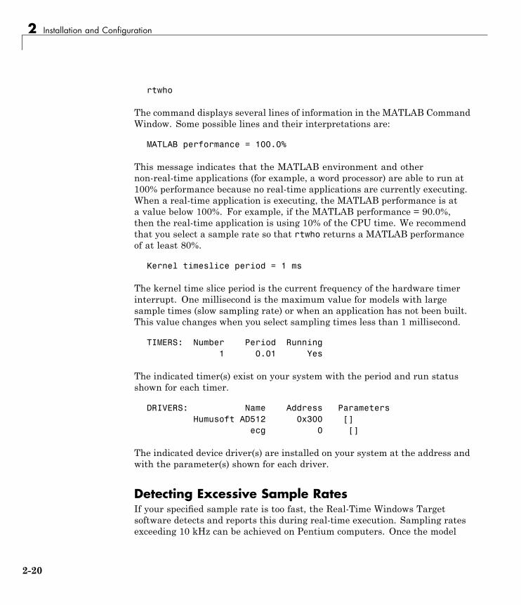
rtwho
The command displays several lines of information in the MATLAB CommandWindow. Some possible lines and their interpretations are:
MATLAB performance = 100.0%
This message indicates that the MATLAB environment and othernon-real-time applications (for example, a word processor) are able to run at100% performance because no real-time applications are currently executing.When a real-time application is executing, the MATLAB performance is ata value below 100%. For example, if the MATLAB performance = 90.0%,then the real-time application is using 10% of the CPU time. We recommendthat you select a sample rate so that rtwho returns a MATLAB performanceof at least 80%.
Kernel timeslice period = 1 ms
The kernel time slice period is the current frequency of the hardware timerinterrupt. One millisecond is the maximum value for models with largesample times (slow sampling rate) or when an application has not been built.This value changes when you select sampling times less than 1 millisecond.
TIMERS: Number Period Running1 0.01 Yes
The indicated timer(s) exist on your system with the period and run statusshown for each timer.
DRIVERS: Name Address ParametersHumusoft AD512 0x300 []
ecg 0 []
The indicated device driver(s) are installed on your system at the address andwith the parameter(s) shown for each driver.
Detecting Excessive Sample RatesIf your specified sample rate is too fast, the Real-Time Windows Targetsoftware detects and reports this during real-time execution. Sampling ratesexceeding 10 kHz can be achieved on Pentium computers. Once the model
2-20

Testing the Installation
is running, you can issue the rtwho command in the MATLAB CommandWindow to observe the system performance.
For example, the following lines show that MATLAB performance hasdecreased because the system is overloaded:
MATLAB performance = 77.1%Kernel timeslice period = 0.001 ms
We recommend that MATLAB performance not fall below 80%.
Demo LibraryThe demo library includes models with preset values and dialog boxes. Thesemodels include a configuration of examples that use no I/O, A/D only, A/D andD/A in a simple signal processing demo, as well as in a simple control demo.Examples that use I/O blocks require you to configure the Adapter block tomatch the I/O board installed in your computer. To see these demo modelsfrom the MATLAB environment:
1 Type rtwtdemo in the MATLAB Command Window.
The rtwtdemo window opens and displays the demo models provided withthe Real-Time Windows Target software:
2 Double-click a demo block to open the model.
To see the Real-Time Windows Target demos from MATLAB Online Help:
2-21

2 Installation and Configuration
1 Launch MATLAB Online Help and choose Demos > Links and Targets> Real-Time Windows Target.
The Real-Time Windows Target Demos page opens and lists the demosprovided with the Real-Time Windows Target software.
2 Click a demo name or icon to open the demo.
2-22

3
Basic Procedures
• “Using Simulink Models” on page 3-2
• “Using Real-Time Applications” on page 3-14
• “Logging Signals to the Base Workspace” on page 3-27
• “Logging Signals to a Disk Drive” on page 3-34
• “Tuning Parameters” on page 3-44

3 Basic Procedures
Using Simulink Models
In this section...
“About Simulink Models” on page 3-2“Creating a Model” on page 3-2“Configuring a Model” on page 3-6“Running a Simulation” on page 3-12
About Simulink ModelsA Simulink model is a graphical representation of your physical system. Youcreate a Simulink model for a non-real-time simulation of your system, andthen you use the Simulink model to create a real-time application.
Creating a ModelYou need to create a Simulink model before you can run a simulation orcreate a real-time application. This procedure explains how to create asimple Simulink model. You can use this model as an example to learn otherprocedures that are useful with Real-Time Windows Target software.
1 In the MATLAB Command Window, type
simulink
The Simulink Library Browser opens. The left pane shows a hierarchy oflibraries and block categories, with the Simulink library at the top. Theright pane shows the blocks available in the category selected on the left.See “Library Browser” for more information.
2 Choose File > New >Model, or click theNewmodel button on the toolbar.
An empty Simulink window opens:
3-2

Using Simulink® Models
3 In the left pane of the Simulink Library Browser window, select Simulink> Sources. Click and drag a Signal Generator block from the browser tothe Simulink window.
Select Continuous. Click and drag a Transfer Fcn block to the Simulinkwindow.
Select Sinks. Click and drag a Scope block to the Simulink window.
4 Connect the Signal Generator output to the Transfer Fcn input byclicking-and-dragging a line between the blocks. Likewise, connect theTransfer Fcn output to the Scope input.
5 Double-click the Transfer Fcn block. The Block Parameters dialog boxopens. In the Numerator text box, enter:
[10000]
In the Denominator text box, enter
[1 70 10000]
Your Block Parameters dialog box looks similar to the next figure.
3-3

3 Basic Procedures
6 Click OK.
7 Double-click the Signal Generator block. The Block Parameters dialog boxopens. From the Wave form list, select square.
In the Amplitude text box, enter
1
In the Frequency text box, enter
20
From the Units list, select rad/sec.
Your Block Parameters dialog box looks similar to the next figure.
3-4

Using Simulink® Models
8 Click OK.
The next figure shows the completed Simulink block diagram, with toolbarand status bar not shown:
9 From the File menu, click Save As. The Save As dialog box opens. In theFile name text box, enter a file name for your Simulink model and clickSave. For example, type
rtwin_model
The Simulink software saves your model in the file rtwin_model.mdl.
To specify a default Real-Time Windows Target configuration set for yourmodel, see “Specifying the Default Configuration Set” on page 3-7. If you
3-5

3 Basic Procedures
activate this configuration set for your model, you can build your real-timeapplication later without setting additional configuration parameters.
To manually configure your model, continue to “Entering ConfigurationParameters Manually” on page 3-8, following. That section teaches you howto enter configuration parameters for your Simulink model, then leads youinto procedures for entering scope parameters and running a non-real-timesimulation of the model.
Model ReferencingThe Real-Time Windows Target software supports model referencing.See “Referencing a Model” in the Simulink User’s Guide guide for moreinformation.
File System Input/OutputLike most real-time environments, the Real-Time Windows Target softwaredoes not include a file system. Therefore, a Simulink model intended for usein a Real-Time Windows Target application cannot use any blocks, such as theTo File or From File block, that generate file I/O calls such as fopen or printf.
If a Real-Time Windows Target model contains any block that tries to performfile system I/O, an error could occur when you try to compile the model,generate code for it, or use External Mode with it. Even if no error occurs, theblock has no effect on either simulation or code execution.
To log signal data without needing a file system, use the techniques describedin “Logging Signals to a Disk Drive” on page 3-34. See “Running a Real-TimeApplication” on page 3-23 for information about using External Mode toexecute a Real-Time Windows Target application.
Configuring a ModelAfter you create a Simulink model, you can enter configuration parametersfor the model. These parameters control many properties of the modelfor simulation and code generation. This section contains the essentialinformation you need when setting configuration parameters for a Real-TimeWindows Target application. For complete information about Simulink
3-6

Using Simulink® Models
configuration parameters, see “Configuration Sets” and “ConfigurationParameters Dialog Box”.
A configuration set is a named set of values for model parameters, such assolver type and simulation start or stop time. Every new model is createdwith a default configuration set, called Configuration, that initially specifiesdefault values for the model’s model parameters. You can subsequently createadditional configuration sets and associate them with the model, as describedin “Referencing Configuration Sets”.
The easiest way to specify configuration parameters for a Real-Time WindowsTarget model is to programmatically assign the default Real-Time WindowsTarget configuration set, as described in “Specifying the Default ConfigurationSet” on page 3-7. You can also set parameters manually, as described in“Entering Configuration Parameters Manually” on page 3-8. Other sectionsdescribe setting configuration patterns for specific purposes.
Specifying the Default Configuration SetAfter you create a Simulink model, you can use the rtwinconfigset functionto specify a default Real-Time Windows Target configuration set for themodel. In most cases, using rtwinconfigset provides all the configurationparameter values that the model needs. The following procedure uses theSimulink model rtwin_model.mdl as an example and assumes you havealready loaded that model (see “Creating a Model” on page 3-2):
1 If you have not already saved the model, from the File menu, click SaveAs. The Save As dialog box opens. In the File name text box, enter a filename for your Simulink model and click Save. For example, type
rtwin_model
The Simulink software saves your model in the file rtwin_model.mdl.
2 In the MATLAB Command Window, type
rtwinconfigset('rtwin_model')
The default Real-Time Windows Target configuration set, RTWin, is nowactive for the rtwin_model model. (Alternatively, you can set the defaultReal-Time Windows Target configuration set by setting the Configuration
3-7

3 Basic Procedures
Parameters System target file option to rtwin.tlc.) You do not needto perform any other configuration for a Real-Time Windows Targetapplication.
3 Save the model.
See “Creating a Real-Time Application” on page 3-19 for a description of howto build your Real-Time Windows Target application.
To revert to the default configuration set, Configuration, or any otherconfiguration set you have for the model, use Model Explorer. This is analternative tool that you can use to enter simulation parameters for a model.See the Simulink documentation for a description of how to use ModelExplorer.
Note Your model uses a Real-Time Windows Target configuration set whenyou change the System target file value to a Real-Time Windows Targetone, such as rtwin.tlc or rtwinert.tlc. The software creates the Real-TimeWindows Target configuration set, RTWin or RTWinERT, only if one doesnot already exist.
Entering Configuration Parameters ManuallyThe configuration parameters give information to Simulink softwarefor running a simulation. This procedure uses the Simulink modelrtwin_model.mdl as an example and assumes you have already loaded thatmodel:
1 In the Simulink window, and from the Simulation menu, clickConfiguration Parameters. In the Configuration Parameters dialogbox, click the Solver tab.
The Solver pane opens.
2 In the Start time field, enter 0.0. In the Stop time field, enter the amountof time you want your model to run. For example, enter 10.0 seconds.
3 From the Type list, choose Fixed-step. Real-Time Workshop codegeneration software does not support variable step solvers.
3-8

Using Simulink® Models
4 From the Solver list, choose a solver. For example, choose the generalpurpose solver ode5 (Dormand-Prince).
5 In the Fixed step size field, enter a sample time. For example, enter0.001 seconds for a sample rate of 1000 samples/second.
6 From the Tasking Mode list, choose SingleTasking. (For models withblocks that have different sample times, choose MultiTasking.)
Your Solver pane looks similar to the next figure.
7 Do one of the following:
• Click Apply to apply the changes to your model and leave the dialogbox open.
• Click OK to apply the changes to your model and close the dialog box.
Entering Scope Parameters for Signal TracingYou enter or change scope parameters to specify the x-axis and y-axis in aScope window. Other properties include the number of graphs in one Scopewindow and the sample time for models with discrete blocks.
3-9

3 Basic Procedures
After you add a Scope block to your Simulink model, you can enter the scopeparameters for signal tracing:
1 In the Simulink window, double-click the Scope block.
A Scope window opens.
2 Click the Parameters button.
A Scope parameters dialog box opens.
3 Click the General tab. In the Number of axes field, enter the number ofgraphs you want in one Scope window. For example, enter 1 for a singlegraph. Do not select the floating scope check box.
In the Time range field, enter the upper value for the time range. Forexample, enter 1 second. From the Tick labels list, choose all.
From the Sampling list, choose Sample time and enter 0 in the text box.Entering 0 indicates that the Simulink software evaluates this block as acontinuous time block. If you have discrete blocks in your model, enter theFixed step size you entered in the Configuration Parameters dialog box.
Your Scope parameters dialog box looks similar to the next figure.
3-10

Using Simulink® Models
4 Do one of the following:
• Click Apply to apply the changes to your model and leave the dialogbox open.
• Click OK to apply the changes to your model and close the dialog box.
5 In the Scope window, point to the y-axis shown in the next figure, andright-click.
6 From the pop-up menu, click Axes Properties.
7 The Scope properties: axis 1 dialog box opens. In the Y-min and Y-maxtext boxes, enter the range for the y-axis in the Scope window. For example,enter -2 and 2 as shown in the next figure.
8 Do one of the following:
3-11

3 Basic Procedures
• Click Apply to apply the changes to your model and leave the dialogbox open.
• Click OK to apply the changes to your model and close the dialog box.
Running a SimulationYou use Simulink normal mode to run a non-real-time simulation. Running asimulation lets you observe the behavior of your model in nonreal time.
After you load your Simulink model into the MATLAB workspace, you canrun a simulation. This procedure uses the Simulink model rtwin_model.mdlas an example and assumes you have loaded that model:
1 In the Simulink window, double-click the Scope block.
The Simulink software opens a Scope window with an empty graph.
2 From the Simulation menu:
• Select Normal mode simulation.
• Choose Start to begin simulation.
The Simulink software runs the simulation and plots the signal data inthe Scope window.
During the simulation, the Scope window displays the samples for onetime range, increases the time offset, and then displays the samples forthe next time range.
3-12

Using Simulink® Models
3 Do one of the following:
• Let the simulation run to the stop time.
• From the Simulation menu, click Stop.
The simulation stops. The MATLAB environment does not display anymessages.
3-13

3 Basic Procedures
Using Real-Time Applications
In this section...
“About Real-Time Applications” on page 3-14“Entering Simulation Parameters” on page 3-14“Entering Scope Parameters for Signal Tracing” on page 3-17“Creating a Real-Time Application” on page 3-19“Entering Additional Scope Parameters for Signal Tracing” on page 3-20“Running a Real-Time Application” on page 3-23“Running an Application from the Command Line” on page 3-25
About Real-Time ApplicationsYou create a real-time application to let your system run while synchronizedto a real-time clock. This allows your system to control or interact with anexternal system. This is necessary if you use your system to stabilize aphysical plant. The first step is to create a Simulink Model, as described inthe previous section, “Using Simulink Models” on page 3-2.
Entering Simulation ParametersAfter you create a Simulink model, you can enter simulation parameters foruse by Real-Time Workshop code generation software for creating C codeand building a real-time application.
This procedure uses the Simulink model rtwin_model.mdl as an example andassumes you have already loaded that model:
1 In the Simulink window, and from the Simulation menu, clickConfiguration Parameters.
2 Click the Real-Time Workshop node.
The Real-Time Workshop pane opens.
3-14

Using Real-Time Applications
3 In the Target selection section, click the Browse button at the RTWsystem target file list.
The System Target File Browser opens.
4 Select the system target file for building a Real-Time Windows Targetapplication, and click OK.
The dialog automatically enters the system target file rtwin.tlc, thetemplate makefile rtwin.tmf, and the make command make_rtw into theReal-Time Workshop pane.
If you have the Real-Time Workshop® Embedded Coder™ product, you canbuild an ERT target application. To build an ERT target application, in theTarget selection section, click the Browse button at the System targetfile list. Click rtwinert.tlc, and then click OK.
Although not visible in the Real-Time Workshop pane, when you clickOK you also configure the external target interface MEX file rtwinext.This allows external mode to pass new parameters to the real-timeapplication and to return signal data from the real-time application. Thedata is displayed in Scope blocks or saved with signal logging.
Your Real-Time Workshop pane looks similar to the next figure.
3-15

3 Basic Procedures
Do not select Inline parameters on the Optimization node. Inliningparameters is used for custom targets when you want to reduce the amountof RAM or ROM with embedded systems. Also, if you select inliningparameters, you disable the parameter tuning feature. Since PCs havemore memory than embedded systems, we recommend that you do notinline parameters.
5 Click the Hardware Implementation node. The following values areset by default:
• Device vendor — Generic
• Device type — 32-bit x86 compatible
• Emulation hardware — None
3-16

Using Real-Time Applications
6 Do one of the following:
• Click Apply to apply the changes to your model and leave the dialogbox open.
• Click OK to apply the changes to your model and close the dialog box.
Entering Scope Parameters for Signal TracingYou enter or change scope parameters to format the x-axis and y-axis in aScope window. Other parameters include the number of graphs in a one Scopewindow and whether the scope is connected to a continuous or discrete model.
If you entered the scope parameters for running a simulation, you can skip thisprocedure. This information is repeated here if you did not run a simulation.
After you add a Scope block to your Simulink model, you can enter the scopeparameters for signal tracing:
1 In the Simulink window, double-click the Scope block.
A Scope window opens.
2 Click the Parameters button.
3-17

3 Basic Procedures
A Scope parameters dialog box opens.
3 Click the General tab. In the Number of axes field, enter the number ofgraphs you want in one Scope window. For example, enter 1 for a singlegraph. Do not select the floating scope check box.
In the Time range field, enter the upper value for the time range. Forexample, enter 1 second. From the Tick labels list, choose all.
From the Sampling list, choose Sample time and enter 0 in the text box.Entering 0 indicates that the Simulink software evaluates this block as acontinuous time block. If you have discrete blocks in your model, enter theFixed step size you entered in the Configuration Parameters dialog box.
Your Scope parameters dialog box looks similar to the next figure.
4 Do one of the following:
• Click Apply to apply the changes to your model and leave the dialogbox open.
• Click OK to apply the changes to your model and close the dialog box.
3-18

Using Real-Time Applications
5 In the Scope window, point to the y-axis and right-click. From the menu,click Axes Properties.
The Scope properties: axis 1 dialog box opens.
6 In the Y-min and Y-max text boxes enter the range for the y-axis in theScope window. For example, enter -2 and 2.
7 Do one of the following:
• Click Apply to apply the changes to your model and leave the dialogbox open.
• Click OK to apply the changes to your model and close the dialog box.
Creating a Real-Time ApplicationThe Real-Time Workshop code generation software creates C code from yourSimulink model, then the Open Watcom C/C++ compiler compiles and linksthat C code into a real-time application.
After you enter parameters into the Configuration Parameters dialog boxfor use by the Real-Time Workshop code generation software, you canbuild a real-time application. This procedure uses the Simulink modelrtwin_model.mdl as an example, and assumes you have loaded that model:
1 In the Simulink window, from the Tools menu, point to Real-TimeWorkshop, and then click Build Model.
The build process does the following:
• The Real-Time Workshop code generation software creates the C codesource files rtwin_model.c and rtwin_model.h.
3-19

3 Basic Procedures
• The make utility make_rtw.exe creates the makefile rtwin_model.mkfrom the template makefile rtwin.tmf.
• The make utility make_rtw.exe builds the real-time applicationrtwin_model.rwd using the makefile rtwin_model.mk created above.The file rtwin_model.rwd is a binary file that we refer to as yourreal-time application. You can run the real-time application with theReal-Time Windows Target kernel.
2 Connect your Simulink model to your real-time application. See “EnteringAdditional Scope Parameters for Signal Tracing” on page 3-20.
After you create a real-time application, you can exit the MATLABenvironment, start the MATLAB environment again, and then connect andrun the executable without having to rebuild.
Entering Additional Scope Parameters for SignalTracingSimulink external mode connects your Simulink model to your real-timeapplication. This connection allows you to use the Simulink block diagram asa graphical user interface to your real-time application.
After you have created a real-time application, you can enter scope parametersfor signal tracing with Simulink external mode:
1 In the Simulation window, and from the Simulation menu, clickConfiguration Parameters.
2 Select the Real-Time Windows Target node.
The Real-Time Windows Target pane opens.
3 Select the External mode check box.
TheMEX-file name label should have an entry of rtwinext. The MEX-filertwinext.mex* is supplied with the Real-Time Windows Target softwareto work with Simulink external mode and support uploading signal dataand downloading parameter values.
The Real-Time Windows Target pane should appear as follows.
3-20

Using Real-Time Applications
4 Click OK.
5 In the Simulation window, and from the Tools menu, click ExternalMode Control Panel.
The External Mode Control Panel dialog box opens.
3-21

3 Basic Procedures
6 Click the Signal & Triggering button.
The External Signal & Triggering dialog box opens.
7 Select the Select all check box. From the Source list, choose manual.From the Mode list, choose normal.
The X under Signal selection indicates that a signal is tagged for datacollection, and T indicates that the signal is tagged as a trigger signal.
8 In the Duration field, enter the number of sample points in a data buffer.For example, to specify a sample rate of 1000 samples/second and a stoptime of 10 seconds, enter
10000
9 Select the Arm when connecting to target check box.
If you do not select this check box, data is not displayed in the Scopewindow.
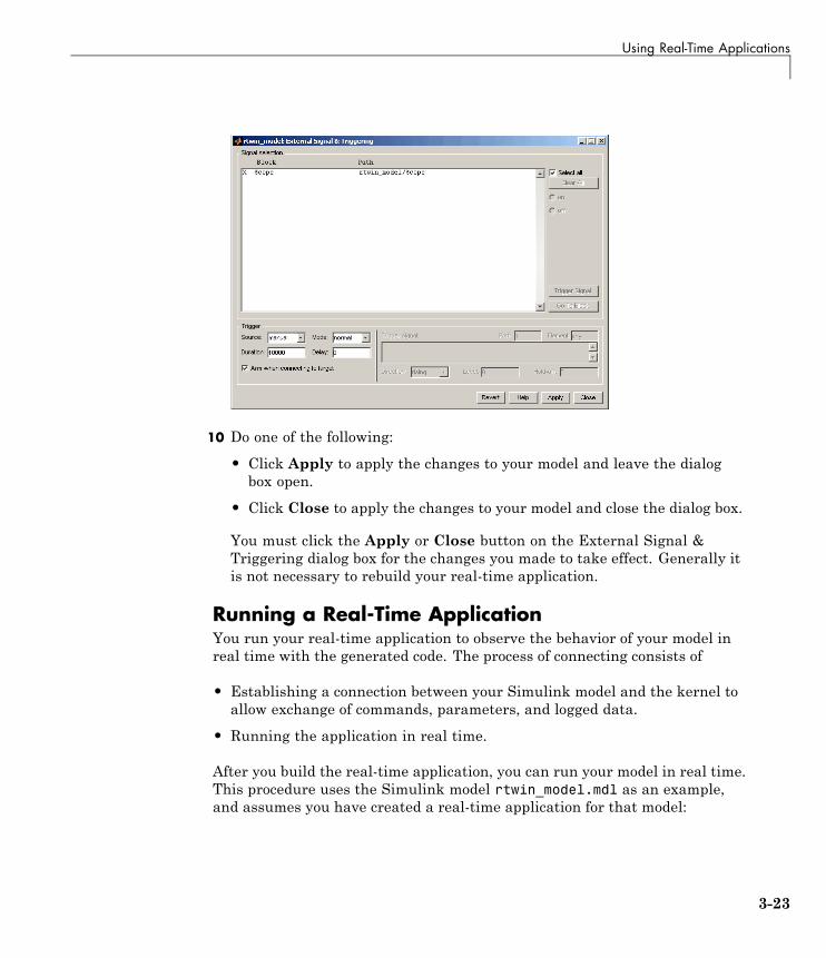
The External Signal & Triggering dialog box looks like this:
3-22
Using Real-Time Applications
10 Do one of the following:
• Click Apply to apply the changes to your model and leave the dialogbox open.
• Click Close to apply the changes to your model and close the dialog box.
You must click the Apply or Close button on the External Signal &Triggering dialog box for the changes you made to take effect. Generally itis not necessary to rebuild your real-time application.
Running a Real-Time ApplicationYou run your real-time application to observe the behavior of your model inreal time with the generated code. The process of connecting consists of
• Establishing a connection between your Simulink model and the kernel toallow exchange of commands, parameters, and logged data.
• Running the application in real time.
After you build the real-time application, you can run your model in real time.This procedure uses the Simulink model rtwin_model.mdl as an example,and assumes you have created a real-time application for that model:
3-23
3 Basic Procedures
1 From the Simulation menu:
• Select External mode simulation.
• Choose Connect To Target.
(You can connect to the target from the toolbar by clicking ).
The MATLAB Command Window displays the message
Model rtwin_model loaded
2 From the Simulation menu, choose Start Real-Time Code.
(You can also start the code from the toolbar by clicking ).
The Simulink software runs the execution and plots the signal data inthe Scope window.
In this example, the Scope window displays 1000 samples in 1 second,increases the time offset, and then displays the samples for the next 1second.
Note Transfer of data is less critical than calculating the signal outputsat the selected sample interval. Therefore, data transfer runs at alower priority in the remaining CPU time after real-time applicationcomputations are performed while waiting for another interrupt to triggerthe next real-time application update. The result may be a loss of datapoints displayed in the Scope window.
3-24

Using Real-Time Applications
3 Do one of the following:
• Let the execution run until it reaches the stop time.
• From the Simulation menu, click Stop Real-time Code.
The real-time application stops.
4 In the Simulation window, and from the Simulation menu, clickDisconnect From Target.
5 From the Simulation menu, click External.
The MATLAB Command Window displays the message
Model rtwin_model unloaded
Running an Application from the Command LineYou can use the MATLAB command-line interface as an alternative to usingthe Simulink GUI. Enter commands directly in the MATLAB CommandWindow or enter them in an M-file.
After you build the real-time application, you can run your model in real time.This procedure uses the Simulink model rtwin_model.mdl as an example,and assumes you have created a real-time application for that model:
1 In the MATLAB Command Window, type
3-25
3 Basic Procedures
set_param(gcs,'SimulationMode','external')
The Simulink software changes to external mode.
2 Type
set_param(gcs,'SimulationCommand','connect')
The MATLAB environment loads the real-time application, connects it tothe Simulink block diagram, and displays the message
Model rtwin_model loaded
3 Type
set_param(gcs,'SimulationCommand','start')
The Simulink software starts running the real-time application.
4 Type
set_param(gcs,'SimulationCommand','stop')
The Simulink software stops the real-time application.
3-26

Logging Signals to the Base Workspace
Logging Signals to the Base Workspace
In this section...
“About Signal Logging” on page 3-27“Entering Scope Parameters” on page 3-27“Entering Signal and Triggering Properties” on page 3-29“Plotting Logged Signal Data” on page 3-31
About Signal LoggingSignal logging to the base workspace is the process of saving (logging) datato a variable in your MATLAB workspace. This allows you to use MATLABfunctions for data analysis and MATLAB plotting functions for visualization.You can save data to a variable during a simulation or during an execution.
Simulink external mode does not support data logging with Outport blocks inyour Simulink model. This means you do not enter or select parameters onthe Data I/O tab in the Configuration Parameters dialog box.
To use signal logging with a Real-Time Windows Target application, you mustadd a Scope block to your Simulink model.
Entering Scope ParametersData is saved to the MATLAB workspace through a Simulink Scope block.Scope block parameters need to be set for data to be saved. After you create aSimulink model and add a Scope block, you can enter the scope parametersfor signal logging to the MATLAB workspace. This procedure uses theSimulink model rtwin_model.mdl as an example, and assumes you havealready loaded that model.
Note If you entered the scope parameters for running a simulation, you maywant to look over this procedure, because the Scope parameters dialog box isrelated to the External Signal and Triggering dialog box.
3-27

3 Basic Procedures
1 In the Simulink window, double-click the Scope block.
A Scope window opens.
2 On the toolbar, click Parameters.
A Scope Parameters dialog box opens.
3 Click the Data history tab.
4 Do one of the following:
• If you are running a simulation, select the Limit data points to lastcheck box, and enter the number of sample points to save.
• If you are running an execution, do not select the Limit data points tolast check box.
The Limit data points to last check box is related to the Durationvalue in the External Signal and Triggering dialog box. The smaller ofeither value limits the number of sample points saved to the MATLABworkspace. When you are using Real-Time Windows Target software, usethe Duration value to set the number of sample points you save. To setthe Duration value, see the next section.
5 Select the Save data to workspace check box. In the Variable nametext box, enter the name of a MATLAB variable. The default name isScopeData.
6 From the Format list, choose Structure with time, Structure, or Array(compatible with V2.0-2.2). For example, to save the sample times andsignal values at those times, choose Structure with time.
Your Data history pane looks similar to the next figure.
3-28

Logging Signals to the Base Workspace
7 Do one of the following:
• Click Apply to apply the changes to your model and leave the dialogbox open.
• Click OK to apply the changes to your model and close the dialog box.
When you modify anything in the Scope parameters dialog box, you mustclick the Apply or OK button for the changes to take effect, and you mustrebuild your real-time application before connecting and starting it. If youdo not rebuild, an error dialog box will open. If you do not click Apply, yourexecutable will run, but it will use the old settings.
The reason why you need to rebuild is because the model checksumincludes settings from the Scope block used for signal logging. If themodel checksum does not match the checksum in the generated code, thereal-time application cannot run. Always rebuild your real-time applicationafter changing Scope parameters.
Entering Signal and Triggering PropertiesData is saved to the MATLAB workspace through a Simulink Scope block.Signal and triggering properties need to be set only when you are runninga real-time application. If you are running a simulation, you can skip thisprocedure.
After you create a Simulink model and add a Scope block, you can enter thesignal and triggering properties for logging to the MATLAB workspace. This
3-29

3 Basic Procedures
procedure uses the Simulink model rtwin_model.mdl as an example andassumes you have already loaded that model:
1 In the Simulink window, and from the Tools menu, click External ModeControl Panel.
The External Mode Control Panel dialog box opens.
2 Click the Signal & Triggering button.
The External Signal & Triggering dialog box opens.
3 Click the Select all button. From the Source list, choosemanual. Fromthe Mode list, choose normal.
The X under Signal selection designates that a signal has been taggedfor data collection, and T designates that the signal has been tagged asa trigger signal.
4 In the Duration field, enter the number of sample points in a data buffer.For example, if you have a sample rate of 1000 samples/second and a stoptime of 10 seconds, you could enter
10000
The Duration value is related to the Limit data points to last value inthe Scope parameters dialog box. The smaller of either value limits thenumber of sample points saved to the MATLAB workspace. We recommendthat you do not select the Limit data points to last check box; use theDuration value to set the number of sample points saved. To clear theLimit data points to last check box, see “Entering Scope Parameters”on page 3-27.
The Duration value specifies the number of contiguous points of data to becollected in each buffer of data. We recommend that you enter a Durationvalue equal to the total number of sample points that you need to collectrather than relying on a series of buffers to be continuous.
If you enter a value less than the total number of sample points, youwill lose sample points during the time needed to transfer values fromthe data buffer to the MATLAB workspace. The Real-Time Windows
3-30

Logging Signals to the Base Workspace
Target software ensures that points are continuous only within one buffer.Between buffers, because of transfer time, some samples will be omitted.
We also recommend setting the time axis for Simulink Scope blocks equalto the sample interval (in seconds) times the number of points in eachdata buffer. This setting will display one buffer of data across the entireSimulink Scope plot.
The External Signal & Triggering dialog box looks similar to the next figure.
5 Do one of the following:
• Click Apply to apply the changes to your model and leave the dialogbox open.
• Click Close to apply the changes to your model and close the dialog box.
You must click the Apply or Close button on the External Signal &Triggering dialog box for the changes you made to take effect. Generally itis not necessary to rebuild your real-time application.
Plotting Logged Signal DataYou can use the MATLAB plotting functions for visualizing non-real-timesimulated data or real-time application data.
3-31

3 Basic Procedures
After running your real-time application and logging data to the MATLABworkspace, you can plot the data. This procedure uses the Simulink modelrtwin_model.mdl as an example, and assumes you saved your data to thevariable ScopeData.
1 In the MATLAB Command Window, type
ScopeData
The MATLAB Command Window shows the structure of the variableScopeData. The variable ScopeData is a MATLAB structure containingfields for the time vector, signal structure, and a string containing theblock name.
ScopeData =time: [10000x1 double]
signals: [1x1 struct]blockName: 'rtwin_model/Scope'
To list the contents of the structure signals, type
ScopeData.signals
The MATLAB Command Window shows the structure of the variableScopeData.signals. This structure contains one or more vectors of signaldata depending on the number of signal inputs to the Scope block.
ans =values: [10000x1 double]
dimensions: 1label: ''title: []
plotStyle: 1
2 To plot the first 1000 points, type
plot(ScopeData.time(1:1000),ScopeData.signals.values(1:1000))
The MATLAB environment plots the first 1000 samples from 0.0000 to0.9990 second.
3-32

Logging Signals to the Base Workspace
3 The variable ScopeData is not automatically saved to your hard disk. Tosave the variable ScopeData, type
save ScopeData
The MATLAB environment saves the scope data to the file ScopeData.mat.
3-33
3 Basic Procedures
Logging Signals to a Disk Drive
In this section...
“About Signal Logging” on page 3-34“Entering Scope Parameters” on page 3-34“Entering Signal and Triggering Properties” on page 3-37“Entering Data Archiving Parameters” on page 3-39“Plotting Logged Signal Data” on page 3-41
About Signal LoggingLogging signals to a disk drive is the process of saving (logging) data to avariable in your MATLAB workspace and then saving that data to a MAT-fileon your disk drive. This allows you to use MATLAB functions for dataanalysis and MATLAB plotting functions for visualization.
Using the data archiving feature provided in the External Mode ControlPanel, you can save data to a file during execution. Simulink external modedoes not support data logging with Outport blocks in your Simulink model.This means you do not enter or select parameters on the Data I/O pane in theConfiguration Parameters dialog box.
To use the data archiving feature with a Real-Time Windows Targetapplication, you must add a Scope block to your Simulink model, and youmust execute a real-time application.
Entering Scope ParametersYou save data to a disk drive by first saving the data to the MATLABworkspace through a Simulink Scope block. You need to set scope blockparameters for data to be saved.
After you create a Simulink model and add a Scope block, you can enter thescope parameters for signal logging to a disk drive. This procedure uses theSimulink model rtwin_model.mdl as an example, and assumes you havealready loaded that model.
3-34

Logging Signals to a Disk Drive
Note If you entered the scope parameters for running a simulation, youmay want to look over this procedure, because the Scope parameters dialogbox is related to the External Signal & Triggering dialog box and the DataArchiving dialog box.
1 In the Simulink window, double-click the Scope block.
A Scope window opens.
2 On the toolbar, click the Parameters button.
A Scope parameters dialog box opens.
3 Click the Data history tab.
4 Do one of the following:
• If you are running a simulation, you can select the Limit data pointsto last check box, and enter the number of sample points to save.
• If you are running an execution, do not select the Limit data points tolast check box.
The Limit data points to last check box is related to the Duration valuein the External Signal & Triggering dialog box. The smaller of either valuelimits the number of sample points saved to the MATLAB workspace.When using Real-Time Windows Target software, we recommend that youuse the Duration value to set the number of sample points you save. Toset the Duration value, see “Entering Signal and Triggering Properties”on page 3-37.
5 Select the Save data to workspace check box. In the Variable nametext box, enter the name of a MATLAB variable. The default name isScopeData.
3-35

3 Basic Procedures
The Scope parameters dialog box is related to the Data Archiving dialogbox. In the Scope parameters dialog box, you must select the Save datato workspace check box to be able to save data to a disk drive, for tworeasons:
• The data is first transferred from the data buffer to the MATLABworkspace before being written to a MAT-file.
• The Variable name entered in the Scope parameters dialog box is thesame as the one in the MATLAB workspace and the MAT-file.
If you do not select the Save data to workspace check box, the MAT-filesfor data logging will be created, but they will be empty.
6 From the Format list, choose eitherStructure with time, Structure, orArray(compatible with Version 2.0 through Version 2.2). For example, tosave the sample times and signal values at those times, choose Structurewith time. Your Data history pane looks similar to the next figure.
7 Do one of the following:
• Click Apply to apply the changes to your model and leave the dialogbox open.
• Click OK to apply the changes to your model and close the dialog box.
3-36

Logging Signals to a Disk Drive
You must rebuild your real-time application before connecting and startingthe application with changed settings. If you do not rebuild after makingchanges, an error will occur.
Entering Signal and Triggering PropertiesData is saved to a disk drive by first saving the data to the MATLABworkspace through a Simulink Scope block. Signal and triggering propertiesneed to be set when running a real-time application.
After you create a Simulink model and add a Scope block, you can enterthe signal and triggering properties for data logging to a disk drive. Thisprocedure uses the Simulink model rtwin_model.mdl as an example, andassumes you have already loaded that model:
1 In the Simulink window, and from the Tools menu, click External ModeControl Panel.
The External Mode Control Panel dialog box opens.
2 Click the Signal & Triggering button.
The External Signal & Triggering dialog box opens.
3 Click the Select all button. From the Source list, choosemanual. Fromthe Mode list, choose normal.
The X under Signal selection designates that a signal has been taggedfor data collection, and T designates that the signal has been tagged asa trigger signal.
4 In the Duration field, enter the number of sample points in a data buffer.For example, if you have a sample rate of 1000 samples/second and a stoptime of 10 seconds, then enter
10000
The Duration value is related to the Limit data points to last value inthe Scope parameters dialog box. The smaller of either value limits thenumber of sample points saved to the MATLAB workspace. We recommendthat you do not select the Limit data points to last check box, and usethe Duration value to set the number of sample points saved.
3-37

3 Basic Procedures
The Duration value specifies the number of contiguous points of data to becollected in each buffer of data. We recommend that you enter a Durationvalue equal to the total number of sample points you need to collect for arun. If you enter a value much less than the total number of sample points,you may lose logging sample points due to the time needed to transfervalues from the data buffer to the MATLAB workspace.
We also recommend setting the time axis for Simulink Scope blocks equalto the sample interval (in seconds) times the number of points in eachdata buffer. This setting will display one buffer of data across the entireSimulink Scope plot.
The External Signal & Triggering dialog box looks similar to the next figure.
5 Do one of the following:
• Click Apply to apply the changes to your model and leave the dialogbox open.
• Click Close to apply the changes to your model and close the dialog box.
You must click the Apply or Close button on the External Signal &Triggering dialog box for the changes you made to take effect, but you donot have to rebuild your real-time application.
3-38

Logging Signals to a Disk Drive
Entering Data Archiving ParametersThe Data Archiving dialog box is related to the Scope parameters dialogbox. In the Scope parameters dialog box, you must select the Save data toworkspace check box to be able to save data to a disk drive, for two reasons:
• The data is first transferred from the scope data buffer to the MATLABworkspace before being written to a MAT-file.
• The Variable name entered in the Scope parameters dialog box is thesame as the one in the MATLAB workspace and the MAT-file. Enablingthe data to be saved enables a variable named with the Variable nameparameter to be saved to a MAT-file.
If you do not select the Save data to workspace check box in the Scopeparameters dialog box, the MAT-files for data logging will be created, butthey will be empty.
After you create a Simulink model, you can enter the Data ArchivingParameters for data logging to a disk drive:
1 In the Simulation window, and from the Tools menu, click ExternalMode Control Panel.
The External Mode Control Panel dialog box opens:
3-39
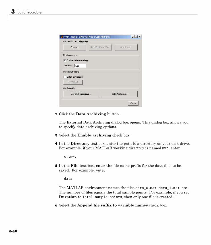
3 Basic Procedures
2 Click the Data Archiving button.
The External Data Archiving dialog box opens. This dialog box allows youto specify data archiving options.
3 Select the Enable archiving check box.
4 In the Directory text box, enter the path to a directory on your disk drive.For example, if your MATLAB working directory is named mwd, enter
c:\mwd
5 In the File text box, enter the file name prefix for the data files to besaved. For example, enter
data
The MATLAB environment names the files data_0.mat, data_1.mat, etc.The number of files equals the total sample points. For example, if you setDuration to Total sample points, then only one file is created.
6 Select the Append file suffix to variable names check box.
3-40

Logging Signals to a Disk Drive
Within each MAT-file, a variable is saved with the same name youentered in the Variable name text box (Data history pane on theScope parameters dialog box). By selecting the Append file suffix tovariable names check box, the same suffix that is added to the MAT-fileis added to the variable name. For example, if you entered the variablename ScopeData, then within the file data_0.mat will be a variableScopeData_0.
Your External Data Archiving dialog box looks similar to the next figure.
7 Click the Close button.
The parameters you entered are applied to your model.
There is no Apply button with this dialog box. You must click the Closebutton for the changes you make to take effect.
Plotting Logged Signal DataYou can use the MATLAB plotting functions for visualization of yournon-real-time simulated data or your real-time executed data.
After running your real-time application and logging data to a disk drive, youcan plot the data. This procedure uses the Simulink model rtwin_model.mdlas an example, and assumes you saved your data to the variable ScopeData:
1 In the MATLAB Command Window, type
ScopeData
3-41

3 Basic Procedures
The MATLAB Command Window shows the structure of the variableScopeData. The variable ScopeData is a MATLAB structure containing thefields time vector, signal structure, and a string containing the block name.
ScopeData =time: [10000x1 double]
signals: [1x1 struct]blockName: 'rtwin_model/Scope'
2 To list the MAT-files saved to your disk drive, type
dir *.mat
The MATLAB Command Window shows the MAT-files in your currentworking directory.
ScopeData.mat
3 To clear the MATLAB workspace and load the scope data, type
clearload ScopeDatawho
The MATLAB Command Window displays:
Your variables are:ScopeData
4 To plot the first 1000 points, type
plot(ScopeData.time(1:1000), ScopeData_0.signals.values(1:1000))
The MATLAB environment plots the first 1000 samples from 0.0000 to0.9990 second.
3-42

Logging Signals to a Disk Drive
3-43

3 Basic Procedures
Tuning Parameters
In this section...
“About Parameter Tuning” on page 3-44“Changing Model Parameters” on page 3-45
About Parameter TuningSimulink external mode connects your Simulink model to your real-timeapplication. The block diagram becomes a graphical user interface to thereal-time application You can change parameter values while running thereal-time application by changing the values in
• Block parameters — Change block parameters by changing the valuesin the dialog boxes associated with the Simulink blocks. Once you changea value, and click OK, the new value is downloaded to the real-timeapplication.
Note Opening a dialog box for a source block causes Simulink to pause.While Simulink is paused, you can edit the parameter values. You mustclose the dialog box to have the changes take effect and allow Simulinkto continue.
• MATLAB variables — Change MATLAB variables by entering thechanges through the MATLAB command line, and then press Ctrl+D forthe changes to be downloaded to your executable. An alternative method todownload parameters is to click Update Diagram from the Edit menuin your Simulink window. Simply changing the value of the MATLABvariable at the MATLAB command line is not sufficient for the Simulinksoftware to know that the value has changed.
Simulink external mode also supports side-effects functions. For example,given an expression in a Gain block of 2*a+b, the expression is evaluated andthe resulting value is exported to the real-time application during execution.
3-44

Tuning Parameters
When a parameter in a Simulink model is changed, the communicationmodule rtwinext.mex* transfers the data to the external real-timeapplication and changes the model parameters. Only the parameters that donot result in model structure modification can be changed. If the structureis modified, you must recompile the model. Model structure changes aredetected automatically using model checksum and reported to the MATLABCommand Window to avoid conflicts.
Changing Model ParametersYou must use Simulink external mode to change model parameters. Whileexternal mode is running, you can open Simulink blocks and changeparameter values. External mode will transfer the new value to the real-timeapplication.
Note Opening a dialog box for a source block causes Simulink to pause. WhileSimulink is paused, you can edit the parameter values. You must close thedialog box to have the changes take effect and allow Simulink to continue.
After you start running your real-time application, you can change parametersand observe the changes to the signals. To start a real-time application, see“Running a Real-Time Application” on page 3-23.
The following procedure uses the Simulink model rtwin_model.mdl asan example. It assumes you have created a real-time application and areexecuting it.
1 From the Simulation menu, click Start Real-Time.
The real-time execution starts running and signal data is displayed inthe Scope window.
3-45

3 Basic Procedures
2 From the Simulink block diagram, double-click the Transfer Function block.
The Block Parameters: Transfer Fcn dialog box opens:
3 In the Denominator field, change 70 to 30. Click OK.
The effect of changing a block parameter is shown in the Scope window.
3-46

Tuning Parameters
3-47

3 Basic Procedures
3-48

4
Boards, Blocks, and Drivers
• “Introduction” on page 4-2
• “Using I/O Boards” on page 4-3
• “Using I/O Driver Blocks” on page 4-10
• “Using Analog I/O Drivers” on page 4-16
• “Using Vector CAN Drivers” on page 4-21

4 Boards, Blocks, and Drivers
IntroductionReal-Time Windows Target software includes driver blocks for more than 200I/O boards. These driver blocks connect the physical world to your real-timeapplication.
4-2

Using I/O Boards
Using I/O Boards
In this section...
“About I/O Boards” on page 4-3“Installing and Configuring I/O Boards and Drivers” on page 4-3“ISA Bus Board” on page 4-7“PCI Bus Board” on page 4-7“PC/104 Board” on page 4-8“Compact PCI Board” on page 4-8“PCMCIA Board” on page 4-9
About I/O BoardsTypically I/O boards are preset from the factory for certain base addresses,voltage levels, and unipolar or bipolar modes of operation. Boards ofteninclude switches or jumpers that allow you to change many of these initialsettings. For information about setting up and installing any I/O board, readthe board manufacturer’s documentation.
For an online list of all I/O boards that Real-Time Windows Target softwaresupports, see Supported I/O Boards.
Installing and Configuring I/O Boards and DriversA Real-Time Windows Target model connects to a board by including an I/Odriver block. This block provides an interface to the board’s device driver andall board-specific settings. The device drivers included with the Real-TimeWindows Target software usually provide the same flexibility of settingsoffered by the board manufacturer. You can enter I/O board settings by usingthe I/O Block Parameters dialog box; setting jumpers and switches on theboard; or both. The three types of board settings are:
• Software selectable — Specify the desired settings in the I/O BlockParameters dialog box. The driver writes the settings you specify to theboard. Examples include A/D gain inputs and selecting unipolar or bipolarD/A outputs.
4-3

4 Boards, Blocks, and Drivers
• Hardware selectable and software readable — Specify the desiredsettings by configuring jumpers or switches on the board. The driver readsthe settings you selected and displays them in the I/O Block Parametersdialog box.
• Hardware selectable, but not software readable — Set jumpers orswitches on the physical board, and then enter the same settings in the I/OBlock Parameters dialog box. These entries must match the hardwarejumpers or switches you set on the board. This type of setting is necessarywhen the board manufacturer does not provide a means for the I/O driverto write or read all board settings. Examples include base address, D/Again, and differential or single-ended A/D inputs.
You can configure a Real-Time Windows Target model to use an I/O boardwhether or not the board exists in the computer, but you will not be able to runthe model until the board is installed with any jumpers or switches correctlyset. Details of installation and configuration depend on the data transferdirection and the specific board, but are essentially similar in all cases.Details for various types of boards and drivers appear later in this chapter.
The following instructions use the Humusoft® AD512 I/O board as an example,configure the board for analog input, and assume that you have physicallyconfigured and installed the board in your computer before you add its driverto your model. Customize the steps to provide the results that you need.
To install and configure an I/O board and its driver,
1 Install the board in the computer, setting any jumpers or switches asneeded.
2 In the model window, choose View > Library Browser to display theSimulink Library Browser.
3 Clone an appropriate Input or Output driver block to your model from theReal-Time Windows Target library.
4 Double-click the cloned I/O driver block.
The I/O Block Parameters dialog box opens. For an Analog Input block, thedialog box initially looks like this:
4-4

Using I/O Boards
5 Click Install new board. From the list that appears, point to amanufacturer, then select a board type. For example, point to Humusoft,then click AD512:
The I/O board dialog box opens. The name of this dialog box depends onwhich I/O board you selected. The box for the Humusoft AD512 boardlooks like this:
6 Select one of the following, as appropriate to the board:
4-5

4 Boards, Blocks, and Drivers
• For an ISA bus board, enter a hexadecimal base address. This valuemust match the base address jumpers or switches set on the physicalboard. For example, to enter a base address of 0x300, in the Addressbox type
300
You can also select the base address by checking boxes A9 through A3.
• For a PCI bus board, enter the PCI slot or check Auto-detect.
7 The I/O Block Parameters dialog also lets you set other I/O blockparameters, such as the sample time. Set such parameters as needed.
8 Click Test.
The Real-Time Windows Target kernel tries to connect to the selectedboard, and if successful, displays the following message.
9 Click OK on the message box, and again on the I/O Block Parametersdialog box.
The I/O Block Parameters dialog box closes, and the parameter values areincluded in your Simulink model.
Multiple Boards of Identical TypeWhen multiple boards of identical type exist, you must execute the completeinstallation sequence for each board, just as you would if the boards were ofdifferent types. Thus two identical PCI boards would result in two entries inthe drop-down list of installed boards. The entries would differ only in thePCI slot number shown for each board.
4-6
Using I/O Boards
Autodetecting Multiple Boards. The Autodetect feature cannot be usedto locate multiple boards of the same type. You must specify their PCI slotnumbers manually.
Multiple Driver Blocks for One BoardOnce you have used the I/O Block Parameters dialog box to add a board andconfigure its driver, you can add additional I/O driver blocks that connect tothe same board from other locations in the model. To accomplish this, clonethe appropriate driver block, open its I/O Block Parameters dialog box, andchoose the board from the list of installed boards.
Scope of Driver Block Parameters. All I/O driver blocks that use a givenboard share identical parameters. You need to specify these parametersonly once, when you first add the board and configure its driver. If yousubsequently change a parameter in any driver block connected to a board,the same change occurs in all the other driver blocks connected to that board.
ISA Bus BoardMost ISA bus I/O boards are preset with a base address of 0x300. If you areusing multiple I/O boards or other boards (for example, network cards) thatalready use the address 0x300, you must set your board with another baseaddress.
In the I/O board dialog box, enter the same base address that you set on thephysical board. You open the I/O board dialog box from any I/O driver BlockParameters dialog box.
PCI Bus BoardYou do not have to set a base address with a PCI board. The plug-and-playfeature of the Windows operating system assigns a PCI slot number. You canenter the slot number in the I/O board dialog box, or you can let the driverdetermine the slot number for you. You open the I/O board dialog box fromany I/O driver Block Parameters dialog box.
We recommend that before you use a PCI or PCMCIA board, you install thedrivers supplied by the board manufacturer. The Real-Time Windows Targetsoftware does not use these manufacturer-supplied drivers. However, they
4-7

4 Boards, Blocks, and Drivers
sometimes initiate the plug-and-play recognition of the board. Without thesedrivers installed, the board might be invisible to your computer and to theReal-Time Windows Target software.
Writing PCI Bus Board DriversReal-Time Windows Target applications cannot use Windows DLLs andkernel-mode drivers, which are not suitable for real-time operation. Thedevice drivers supported by the Real-Time Windows Target software arelisted at Supported I/O Boards. If no driver is listed for the board that youwant to use, you may be able to write a custom device driver.
A user-written custom device driver must program the board directly atthe register level, which is the technique used by all supported Real-TimeWindows Target drivers. If the board registers are I/O-mapped, the Real-TimeWindows Target software supports such programming. If the registers arememory-mapped, programming them would require mapping their memoryregion to Real-Time Windows Target address space, which the Real-TimeWindows Target software does not support for user-written drivers.
If you want to use an unsupported board that you believe should be supported,or you need assistance with user-written Real-Time Windows Target devicedrivers, including the case of a board with memory-mapped registers, contactThe MathWorks Technical Support.
PC/104 BoardMost PC/104 bus I/O boards are preset with a base address of 0x300. If youare using multiple I/O boards or other boards (for example, network cards)that already use the address 0x300, you must set your board with anotherbase address.
In the I/O board dialog box, enter the same base address that you set on thephysical board. You open the I/O board dialog box from any I/O driver BlockParameters dialog box.
Compact PCI BoardUsing a compact PCI board requires that you use a compact PC (industrialPC). In addition, you need to install the Windows operating system, the
4-8

Using I/O Boards
MATLAB environment, Simulink software, and Real-Time Windows Targetsoftware on the compact PC.
PCMCIA BoardThe plug-and-play feature of the Windows operating system assigns a baseaddress automatically. You can enter this address in the I/O board dialog box,or you can let the driver determine the address for you. You open the I/Oboard dialog box from any I/O driver Block Parameters dialog box.
We recommend that before you use a PCI or PCMCIA board, you install thedrivers supplied by the board manufacturer. Real-Time Windows Targetsoftware does not use these manufacturer-supplied drivers. However, theysometimes initiate the plug-and-play recognition of the board. Without thesedrivers installed, the board might be invisible to your computer and to theReal-Time Windows Target software.
4-9

4 Boards, Blocks, and Drivers
Using I/O Driver Blocks
In this section...
“About I/O Driver Blocks” on page 4-10“The Real-Time Windows Target Library” on page 4-10“Output Signals from an I/O Block” on page 4-11“Variations with Channel Selection” on page 4-12
About I/O Driver BlocksReal-Time Windows Target I/O driver blocks allow you to select and connectspecific analog channels and digital lines to your Simulink model throughI/O driver blocks. These blocks provide an interface to your physical I/Oboards and your real-time application. They ensure that the C code created byReal-Time Workshop code generation software correctly maps block diagramsignals to the appropriate I/O channels. All I/O blocks support all applicableSimulink datatypes.
You can have multiple I/O blocks associated with each type of I/O board. Forexample, you can have one Analog Input block for channels 1 to 4 and anotherblock for channels 5 to 8. Each I/O block in a model specifies its own blockconfiguration parameters, which apply only to that instance of that block. See“Blocks — Alphabetical List” for a description of the configuration parametersfor each I/O block.
The Real-Time Windows Target Library provides blocks that you can use withsupported I/O boards. You can also create your own I/O blocks to work withReal-Time Windows Target software. See Appendix A, “Custom I/O DriverBlocks” for details.
The Real-Time Windows Target LibraryAll Real-Time Windows Target I/O driver blocks are available in theReal-Time Windows Target Library. To view this library from the MATLABCommand Window, type:
rtwinlib
4-10

Using I/O Driver Blocks
To view the Real-Time Windows Target Library from a model:
1 In the model window, choose View > Library Browser.
The Simulink Library Browser opens. The left pane shows a hierarchy oflibraries and categories, with the Simulink library at the top. The rightpane shows the blocks available in the category selected on the left. See“Library Browser” for more information.
2 In the left column, double-click Real-Time Windows Target.
The Real-Time Windows Target library opens.
You can add any I/O block in the library to your Simulink model by draggingit from the library to the model. After you add the block, connect it toyour model as you would any other block, and provide block configurationparameter values as described for the block in “Blocks — Alphabetical List”.
Output Signals from an I/O BlockI/O driver blocks output multiple signals as a vector instead of individualchannels or lines. To connect the individual channels and lines to parts ofyour Simulink model, you need to separate the vector with a Demux block.
After you add and configure an I/O driver block in your Simulink model, youcan separate and connect the output signals from the blocks:
1 In the Simulink window, choose View > Library Browser.
The Simulink Library Browser opens.
2 In the Simulink library, click Signal Routing. From the list in the rightpane, click and drag Demux to your Simulink model.
3 Double-click the Demux block. The Block Parameters: Demux dialog boxopens. Enter the number of lines leaving the Demux block. For example, ifyou entered three channels in the Analog Input driver block, enter 3 in theNumber of outputs box.
4-11

4 Boards, Blocks, and Drivers
4 Click OK.
5 Finish making connections and selecting display options.
• Connect the Analog Input block to the Demux block input.
• Connect each of the Demux block output lines to the input of other blocks.
• In the Simulink window, and from the Format menu, click Port/SignalDisplays > Wide Nonscalar Lines, and click Signal Dimensions.
In this simple example, inputs 1 and 2 are not connected, but they could beconnected to other Simulink blocks.
Variations with Channel SelectionFor a better understanding of how to specify device settings when usingboth analog and digital signals, this section uses the Keithley® Metrabyte™DAS-1601 I/O board as an example. The following is a specification summaryof the DAS-1601 board:
• Analog input (A/D) — 16 single-ended or 8 differential analog inputs(12-bit), polarity is switch configured as either unipolar (0 to 10 volts) orbipolar (+/- 10 volts). Gain is software configured to 1, 10, 100, and 500.
• Digital input — Four unidirectional digital inputs
• Analog output (D/A) — Two analog outputs (12-bit). Gain is switchconfigured as 0 to 5 volts, 0 to 10 volts, +/- 5 volts, or +/- 10 volts
4-12

Using I/O Driver Blocks
• Digital output — Four unidirectional digital outputs
• Base address — Switch configured base address
This section explores different configurations for input signals.
Once an Analog Input block has been placed in the model and the I/O boardselected and configured, you can set up the Analog Input block to handleinput signals.
Single analog input — The most basic case is for a single analog inputsignal that will be physically connected to the first analog input channel onthe board. In the Block Parameter: Analog Input dialog box, and the Inputchannels box, enter
1 or [1]
The use of brackets is optional for a single input.
Input vector with differential analog — Analog channels are numberedstarting with channel 1 and continue until you reach a number correspondingto the maximum number of analog signals supported by the I/O board.
In the case of the DAS-1601, when configured as differential inputs, eightanalog channels are supported. The analog input lines are numbered 1through 8. The complete input vector is
[1 2 3 4 5 6 7 8] or [1:8]
If you want to use the first four differential analog channels, enter
[1 2 3 4]
Input vector with single-ended analog — Now, assume your DAS-1601board is configured to be single-ended analog input. In this case, 16 analoginput channels are supported. The complete input vector is
[1 2 3 4 5 6 7 8 9 10 11 12 13 14 15 16] or [1:16]
To use the first four single-ended analog input channels, enter
4-13

4 Boards, Blocks, and Drivers
[1 2 3 4] or [1:4]
The next figure shows the resulting block diagram.
We do not recommend specifying more channels than you actually use in yourblock diagram. This results in additional overhead for the processor with A/Dor D/A conversions. In this case, for example, even though some channels arenot actually used in the block diagram, these channels are still converted.
You could attach terminator blocks to channels 4 and 5 inside your blockdiagram after passing the Analog Input block vector in to a Demux block.Adding terminator blocks provides you with graphical information in yourblock diagram to clearly indicate which channels you connected and which areavailable. The penalty is that even the terminated channels are converted,adding some computational overhead.
The next figure shows the block implementation.
4-14

Using I/O Driver Blocks
Depending on the board and the number of channels used, I/O conversion timecan affect the maximum sample rate that can be achieved on your system.Rather than converting unused channels, we recommend specifying only theset of channels that are actually needed for your model.
4-15

4 Boards, Blocks, and Drivers
Using Analog I/O Drivers
In this section...
“About Analog Drivers” on page 4-16“I/O Driver Characteristics” on page 4-16“Normalized Scaling for Analog Inputs” on page 4-17
About Analog DriversControl systems have unique requirements for I/O devices used withReal-Time Windows Target applications. For information about writingcustom I/O device drivers to work with Real-Time Windows Targetapplications, see Appendix A, “Custom I/O Driver Blocks”.
I/O Driver CharacteristicsReal-Time Windows Target applications use off-the-shelf I/O boards providedby many hardware vendors. These boards are often used for data acquisitionindependently of Real-Time Windows Target software. In such environments,board manufacturers usually provide their own I/O device drivers for dataacquisition purposes. This use differs significantly from the behavior ofdrivers provided with Real-Time Windows Target software.
In data acquisition applications, data is often collected in a burst or frameconsisting of many points, perhaps 1,000 or possibly more. The burst ofdata becomes available once the final point is available. This approach isnot suitable for use in automatic control applications, because it results inunacceptable latency for most or all data points.
In contrast, drivers used by Real-Time Windows Target applications capturea single point of data at each sample interval. Considerable effort is made tominimize the latency between collecting a data point and using the data inthe control system algorithm. This is the reason why a board that specifies amaximum sample rate (for data acquisition) might be described as achievingsample rates well in excess of the rates that are achievable by Real-TimeWindows Target applications. For data acquisition, such boards usuallyacquire data in bursts and not in a point-by-point fashion, which is moreappropriate for stable control systems.
4-16

Using Analog I/O Drivers
Normalized Scaling for Analog InputsReal-Time Windows Target software allows you to normalize I/O signalsinternal to the block diagram. Generally, inputs represent real-world valuessuch as angular velocity, position, temperature, pressure, and so on. Thisability to choose normalized signals allows you to
• Apply your own scale factors
• Work with meaningful units without having to convert from voltages
When using an Analog Input block, you select the range of the externalvoltages that are received by the board, and you choose the block outputsignal. For example, the voltage range could be set to 0 to +5 V, and theblock output signal could be chosen as Normalized unipolar, Normalizedbipolar, Volts, or Raw.
If you prefer to work with units of voltage within your Simulink blockdiagram, you can choose Volts.
If you prefer to apply your own scaling factor, you can choose Normalizedunipolar or Normalized bipolar, add a Gain block, and add an offset toconvert to a meaningful value in your model.
If you prefer unrounded integer values from the analog-to-digital conversionprocess, you can choose Raw.
0 to +5 Volts and Normalized BipolarFrom the Input range list, choose 0 to +5 V, and from the Block outputsignal list, choose Normalized bipolar. This example converts anormalized bipolar value to volts, but you could also easily convert directlyto another parameter in your model.
0 to 5 volts --> ([-1 to 1] normalized + 1) * 2.5
In your block diagram, you can do this as follows.
4-17

4 Boards, Blocks, and Drivers
0 to +5 Volts and Normalized UnipolarFrom the Input range list, choose 0 to +5 V, and from the Block outputsignal list, choose Normalized unipolar. This example converts anormalized unipolar value to volts, but you could also easily convert directlyto another parameter in your model.
0 to 5 volts --> ([0 to 1] normalized * 5.0
In your block diagram, you can do this as follows.
-10 to +10 Volts and Normalized BipolarFrom the Input range list, choose -10 to +10 V, and from the Blockoutput signal list, choose Normalized bipolar. This example converts anormalized bipolar value to volts, but you could also easily convert directlyto another parameter in your model.
-10 to 10 volts --> [-1 to +1] normalized * 10
In your block diagram, you can do this as follows.
4-18

Using Analog I/O Drivers
-10 to +10 Volts and Normalized UnipolarFrom the Input range list, choose -10 to +10 V, and from the Blockoutput signal list, choose Normalized unipolar. This example converts anormalized bipolar value to volts, but you could also easily convert directlyto another parameter in your model.
-10 to 10 volts --> ([0 to 1] normalized - 0.5) * 20
In your block diagram, do this as follows.
Normalized Scaling for Analog OutputsAnalog outputs are treated in an equivalent manner to analog inputs.
If the voltage range on the D/A converter is set to 0 to +5 volts, and theBlock input signal is chosen as Normalized bipolar, then a Simulinksignal of amplitude -1 results in an output voltage of 0 volts. Similarly, aSimulink signal of amplitude +1 results in an output voltage of +5 volts.
A voltage range on the D/A converter is set to -10 to +10 volts, and theBlock input signal is chosen as Normalized bipolar, then a Simulinksignal of amplitude -1 results in an output voltage of -10 volts. Similarly, aSimulink signal of amplitude +1 results in an output voltage of +10 volts.
4-19

4 Boards, Blocks, and Drivers
This may require that you adjust your signal amplitudes using a Gain block,Constant block, and Summer block depending on the selected voltage range.
4-20

Using Vector CAN Drivers
Using Vector CAN DriversBefore you can use the Vector Informatik CAN devices, you must install thedrivers for them.
1 Install the Vector CAN devices. See the Vector Informatik GmbHdocumentation for installation instructions for hardware devices such asCANcaseXL, CANboardXL, and CANcardXL, drivers, support libraries,and so on.
2 Ensure that you have the Vector XL driver library for the Windows XPor Windows Vista™ system. If you do not have this library, download itVector Informatik GmbH Web site:
https://www.vector-worldwide.com/va_downloadcenter_us.html
3 Install the driver file.
4 Copy the vxlapi.dll file into the Windows system root\system32directory.
5 Use the Vector software to assign physical CAN channels to an application.When specifying the name for the Real-Time Windows Targets application,use the string MATLAB.
4-21

4 Boards, Blocks, and Drivers
4-22

5
Troubleshooting
• “Introduction” on page 5-2
• “Building Older Models” on page 5-3
• “Plots Not Visible in Simulink Scope Block” on page 5-4
• “Failure to Connect to Target” on page 5-5
• “Scope Output Delayed or Missing” on page 5-6
• “S-Functions Using Math Functions” on page 5-7

5 Troubleshooting
IntroductionSolutions have been worked out for some common errors and problems thatcan occur when you are using Real-Time Windows Target software.
5-2

Building Older Models
Building Older ModelsIf you are building an older model with Real-Time Windows Target software,you might get a message like the following:
"Real-Time Workshop utilizes device specific information (e.g.,
microprocessor word sizes) to reproduce a bit true representation
of the diagram. This information is not specified in this model.
If you continue, Real-Time Workshop will use a 32-bit generic
target setting."
This is simply a warning, and you can ignore the message. To eliminate thismessage, you can use the rtwinconfigset command, as follows:
rtwinconfigset('<model_name>')
5-3

5 Troubleshooting
Plots Not Visible in Simulink Scope BlockFor data to plot correctly in a Simulink Scope block, you must specify thefollowing:
• External mode selected from the Simulation menu in the ConfigurationParameters dialog
• Connect to target selected from the Simulation menu
• Select one or more signals for capture (designated with "X") in the ExternalSignal & Triggering dialog box from the Tools > External Mode ControlPanel menu.
• Duration * Fixed Step Size close to or less than the X range in theScope block
• Correct mode (one-shot vs. normal)
• Appropriate signal levels to allow triggering
• Y range on Simulink Scope block axes large enough to span the signalamplitude
• X range
• Arm when connect to target in the External Signal & Triggering dialogbox or Arm Trigger in the External Mode Control Panel
• Start real-time code selected from the Simulation menu
If you are unable to see signals plotted in your Simulink Scope blocks after allof the above items have been selected, your system might have insufficientCPU time. To determine CPU utilization, type rtwho. The rtwho commandreturns information about MATLAB performance. The value returned isan indicator of how much loading your model places on the CPU. If Scopeblocks fail to plot, this can be an indication that insufficient time is availablebetween sample intervals to allow data to be transferred back to the MATLABenvironment where the plotting is performed. To test for this condition, youcan run one of the demonstration models, or you can try running your modelat a significantly slower rate to determine whether this is the cause. Werecommend that MATLAB performance not fall below 80%.
5-4

Failure to Connect to Target
Failure to Connect to TargetPossible Problem — When trying to connect to the target, the SimulationErrors dialog box displays
Checksum mismatch. Target code needs to be rebuilt.
Solution — This indicates that the model structure has changed since the lasttime code was generated. You must rebuild the real-time application. If yourmodel fails to build successfully, we recommend that you delete .mk and .objfiles from the Real-Time Workshop project directory, and then select Buildfrom the Tools menu.
Possible Problem — When trying to connect to the target, the SimulinkDiagnostic dialog box displays
External mode MEX-file "win_tgt" does not exist or is not on the
MATLAB path.
Solution — Versions 1.0 and 1.5 of the Real-Time Windows Target softwareused the MEX-file win_tgt. For Version 2.2 and later, the MEX-file name waschanged to rtwinext. If you create a new Simulink model, the new filenameis entered correctly. If you have a Simulink model where you used Version 1.0or 1.5, you need to change the filename using the following procedure:
1 In the Simulink window, from the Tools menu, click External ModeControl Panel.
2 On the External Mode Control Panel dialog box, click the Target interfacebutton.
3 In the MEX-file for external mode text box, enter
rtwinext
4 Click OK.
5-5

5 Troubleshooting
Scope Output Delayed or MissingDuring a run, you may notice either slow updates of Scope blocks or acomplete failure to plot data in Scope blocks. This could indicate that thereal-time application sample time (set by Configuration Parameters >Fixed step size) is near the lower threshold for your hardware. Plotting datahas a lower priority than executing the application, so a small sample timemay allow the application to run but leave insufficient resources for plotting.If the sample time is so small that the application itself cannot run, an errormessage is displayed and real-time execution is terminated.
To check the appropriateness of the sample time, type rtwho, then look at thevalue displayed for MATLAB performance. A value less than 80% indicatesthat your sample time may be too small. If this occurs, select a larger sampletime. If necessary, also change the sample time of any I/O drivers to be thesame as the new application sample time, or an integer multiple of that time.Then rebuild the model, connect to the target, and restart the real-timeapplication.
You may need to iterate changing the sample time until scope output appears.You must always rebuild the application after changing the sample time. Ingeneral, we recommend that you start by choosing a larger sample time, thendecreasing it as needed to provide the desired responsiveness and accuracy.For example, initially select a sample time of 0.01 second, and confirm thatyour system runs correctly and plots are displayed.
Sample times can be too large as well as too small. After you have foundan application sample time that gives acceptable Scope block display, againtype rtwho and check MATLAB performance. If MATLAB performance isin the range of 98% or so, consider decreasing your sample time by oneorder of magnitude. After such a change, any previously correct I/O driversample times remain correct, because they are integer multiples of the newapplication sample time.
5-6

S-Functions Using Math Functions
S-Functions Using Math FunctionsPossible problem — When you create your own S-functions that include mathfunctions, the S-functions compile, but you cannot build the application.
Solution — Add the Real-Time Windows Target header to your S-function.For example, add
#include<math.h>#include"rtwintgt.h"
The header #include<math.h> must precede the header#include"rtwintgt.h".
5-7

5 Troubleshooting
5-8

A
Custom I/O Driver Blocks
• “Introduction” on page A-2
• “I/O Register Access from S-Functions Limitation” on page A-3
• “Incompatibility with Win32 API Calls” on page A-4
• “Unsupported C Functions” on page A-5
• “Supported C Functions” on page A-6

A Custom I/O Driver Blocks
IntroductionYou can write custom I/O device drivers to work with Real-Time WindowsTarget applications. We do not recommend using Analog Input, AnalogOutput, Digital Input, or Digital Output drivers as a starting point forcreating custom device drivers.
A-2
I/O Register Access from S-Functions Limitation
I/O Register Access from S-Functions LimitationWindows operating system drivers can access I/O registers only from thereal-time kernel and not from the Simulink software. To ensure that driversdo not attempt to access I/O registers from Simulink S-functions, enter codefragments like the following as appropriate:
#ifndef MATLAB_MEX_FILE/* we are in RTWin kernel, safe to do board I/O */#else/* we are in Simulink, don't do board I/O */#endif
A-3

A Custom I/O Driver Blocks
Incompatibility with Win32 API CallsThe Real-Time Windows Target kernel intercepts the interrupt from thesystem clock. It then reprograms the system clock to operate at a higherfrequency for running your real-time application. At the original clockfrequency, it sends an interrupt to the Windows operating system to allowWindows based applications or any software using the Win32 API to run.
As a result, software that uses the Win32 API cannot be executed as acomponent of your real-time application. Any software you use to writeI/O drivers must not have any calls to the Win32 API.
A-4

Unsupported C Functions
Unsupported C FunctionsIf you create your own custom I/O driver blocks, you should first check forC functions that are supported by Real-Time Windows Target software.Functions that use the Windows operating system are not supported byReal-Time Windows Target software. This is because the kernel interceptsthe system clock and first runs the real-time application. If there is timeleft before the next sample time, the kernel might allow a Windows basedapplication or function to run.
The following list includes many, but not all, of the unsupported functions:
• File I/O — fopen, freopen, fclose, fread, fwrite, fputs, fputc, fgets,fgetc, gets, getc, getchar, puts, putc, putchar, fflush, setbuf, setvbuf
• Console I/O— printf, fprintf, sprintf, vfprintf, vprintf, vsprintf,fscanf, scanf, sscanf
• Process management— spawn, exit, abort, atexit
• Signals and exceptions — signal, longimp, raise
• Time functions — clock, time, difftime, asctime, ctime, difftime,gmtime, localtime, mktime, strftime
• Win32 API functions— No Windows API functions are supported.
A-5

A Custom I/O Driver Blocks
Supported C FunctionsYou can use ANSI C functions that do not use the Windows operating systemin your custom blocks or I/O drivers. The following includes a partial list ofsupported functions:
• Data conversion — abs, atof, atoi, atol, itoa, labs, ltoa, strtod,strtol, strtoul, ultoa
• Memory allocation — calloc, free, malloc
Note Memory allocation is not an operation that can be done in realtime. To work with a Real-Time Windows Target application, memorymanagement must occur before real-time simulation begins. Simulationswitches into real-time after mdlStart, so you can allocate memory inmdlInitializeSizes or mdlStart. You cannot allocate memory in anyfunction after mdlStart, such as mdlOutputs or mdlUpdate.
• Memory manipulation— _memccpy, memcpy, memchr, memcmp, _memicmp,memmove, memset
• String manipulation — strcat, strchr, strcmp, strcpy, strcspn,_strdup, _stricmp, strlen, _strlwr, strncat, strncmp, strncpy,_strnset, strpbrk, strrchr, _strrev, _strset, strspn, strstr, strtok,strupr
• Mathematical — acos, asin, atan, atan2, ceil, cos, cosh, div, exp,fabs, floor, fmod, frexp, ldexp, ldiv, log, log10, max, min, modf, pow,rand, sin, sinh, sqrt, srand, tan, tanh, uldiv
• Character class tests and conversion — isalnum, isalpha, _isascii,iscntrl, isdigit, isgraph, islower, isprint, ispunct, isspace,isupper, isxdigit, isxupper, isxlower, _toascii, tolower, toupper
• Searching and sorting — bsearch, qsort
• Dummy functions — exit, fprintf, prinf
A-6

B
Examples
Use this list to find examples in the documentation.

B Examples
Simulink Model Examples“Specifying the Default Configuration Set” on page 3-7“Entering Configuration Parameters Manually” on page 3-8“Entering Scope Parameters for Signal Tracing” on page 3-9“Running a Simulation” on page 3-12
Real-Time Application Examples“Entering Simulation Parameters” on page 3-14“Entering Scope Parameters for Signal Tracing” on page 3-17“Creating a Real-Time Application” on page 3-19“Entering Additional Scope Parameters for Signal Tracing” on page 3-20“Running a Real-Time Application” on page 3-23“Running an Application from the Command Line” on page 3-25
Signal Logging to MATLAB Workspace Examples“Entering Scope Parameters” on page 3-27“Entering Signal and Triggering Properties” on page 3-29“Plotting Logged Signal Data” on page 3-31
Signal Logging to Disk Drive Examples“Entering Scope Parameters” on page 3-34“Entering Signal and Triggering Properties” on page 3-37“Entering Data Archiving Parameters” on page 3-39“Plotting Logged Signal Data” on page 3-41
B-2

Parameter Tuning Examples
Parameter Tuning Examples“Changing Model Parameters” on page 3-45
I/O Board Examples“Installing and Configuring I/O Boards and Drivers” on page 4-3“The Real-Time Windows Target Library” on page 4-10“Output Signals from an I/O Block” on page 4-11
B-3

B Examples
B-4

Index
IndexAA/D. See analog-to-digitaladding
I/O driver blocks 4-10analog input
normalized scaling 4-17analog-to-digital
channel selection 4-12application
Real-Time Windows Target 1-6
Ccapturing and displaying signals 1-2changing parameters
parameter tuning 1-8channel selection
entering configurations 4-12compact PCI
installing 4-8compatibility
with MathWorks software 1-5compiler
Open Watcom C/C++ only 1-7computer
PC-compatible 1-10configuring
I/O boards and drivers 4-3connecting
real-time application 3-20Simulink model 3-20
creatingreal-time application 3-19Simulink model 1-13
custom I/O driversincompatible with Win32 A-4
DD/A. See digital-to-analog
data archiving parametersentering 3-39logging data to disk drive 3-39
data buffers 1-16default configuration set 3-7demo library
opening 2-21Real-Time Windows Target 2-21
Demux blockseparating I/O signals 4-11
descriptionSimulink external mode 1-15
device driverschannel selection 4-12custom I/O A-1writing custom A-1
digital-to-analogchannel selection 4-12
directoriesinstalled 2-8MATLAB working 2-8project 2-8Real-Time Workshop working 2-8working 2-8
disk driveplotting logged data 3-41signal logging 3-34
Eentering
data archiving parameters 3-39scope properties 3-34signal and triggering properties 3-37simulation parameters for Real-Time
Workshop 3-14simulation parameters for Simulink 3-8
executionreal-time 1-12running in real time 1-13
Index-1

Index
external interface MEX-filertwinext 5-5win_tgt 5-5
external modedescription 1-15parameter tuning 1-8
Ffailure to connect
troubleshooting 5-5features
signal logging 1-7signal tracing 1-7
filesapplication 2-8external mode interface 2-8I/O drivers 2-8installed 2-8kernel install command 2-8make command 2-8makefile 2-8project directory 2-8Real-Time Windows Target directory 2-8system target 2-8system target file 2-8template makefile 2-8working directory 2-8
Hhardware
system requirements 2-6
II/O blocks
input and output 4-10library 4-10separating signals 4-11
I/O boards
compact PCI boards 4-8configuring 4-3installing 4-3ISA bus 4-7overview 4-3PC/104 bus 4-8PCI bus 4-7PCMCIA 4-9
I/O driverscharacteristics 4-16configuring 4-3installing 4-3using 4-16
input blocksoverview 4-10
input/outputsupport 1-10
installingcompact PCI 4-8I/O boards 4-3I/O boards and drivers 4-3kernel overview 2-12Real-Time Windows Target 2-8testing installation 2-17
ISA businstalling 4-7
Kkernel
communication with hardware 1-5installing 2-12scheduler 1-5timer interrupt 1-5uninstalling 2-14
Llogging
data to disk drive 3-34
Index-2

Index
data archiving parameters 3-39data to workspace 3-27
Mmakefile 2-8MathWorks
compatible software 1-5Simulink blocks 1-5
MATLAB workspacesignal logging 3-27
memory managementlimitation on A-6
model parameterschanging 3-45parameter tuning 3-45
Nnonreal time
simulation 3-12normalized scaling
analog input 4-17
Oopening demo library 2-21output blocks
overview 4-10overview
I/O boards 4-3input blocks 4-10installing kernel 2-12output blocks 4-10parameter tuning 3-44real-time application 3-14system concepts 1-15system requirements 2-6testing installation 2-17
Pparameter tuning
changing model parameters 3-45changing parameters 1-8external mode 1-8feature 1-8overview 3-44
PCI businstalling 4-7
PCMCIA businstalling 4-9
plots not visibletroubleshooting 5-4
plottinglogged data from disk 3-41logged data from workspace 3-31
Rreal-time
control 1-2execution 1-12hardware-in-the-loop 1-2signal processing 1-2
real-time applicationand the development process 1-13connecting to Simulink model 3-20creating 3-19overview 3-14Real-Time Windows Target 1-6Real-Time Workshop parameters 3-14scope properties for signal tracing 3-17simulation parameters for Real-Time
Workshop 3-14software environment 1-6starting 3-23stopping 3-23
real-time kernelReal-Time Windows Target 1-5scheduler 1-5
Index-3

Index
software environment 1-5timer interrupt 1-5
Real-Time Windows Targetapplication 1-6custom I/O device drivers A-1demo library 2-21development process 1-13files 2-8installing kernel 2-12overview 1-2real-time application 1-6real-time kernel 1-5software environment 1-12uninstalling kernel 2-14
Real-Time Windows Target LibraryI/O blocks 4-10
Real-Time Workshopentering simulation parameters 3-14
requirementshardware 2-6software 2-6
rtvdp.mdlSimulink model 2-17
RTWin configuration set 3-7rtwinext
external interface MEX-file 5-5running
execution in real time 1-13real-time application 3-23simulation in nonreal time 3-12
SS-functions
C-code supported in 2-2limitation on I/O register access A-3limitation on memory management A-6M-code not supported in 2-2using math functions in 5-7Win32 calls not usable in 1-5
sample ratesexcessive 2-20
scope outputdelayed or missing 5-6
scope propertiesentering 3-34entering for signal tracing 3-17for signal logging to disk drive 3-34for signal logging to workspace 3-27
separatingI/O signals 4-11
settinginitial working directory 2-10working directory
from MATLAB 2-10from the Desktop icon 2-10
signal and triggeringentering properties 3-29properties 3-37
signal archiving. See signal loggingsignal data
plotting from disk drive 3-41plotting from workspace 3-31
signal loggingentering scope properties 3-27feature 1-7plotting data 3-31signal and triggering properties 3-37to disk drive 3-34to MATLAB workspace 3-27
signal logging to disk drivedata archiving parameters 3-39signal and triggering properties 3-37
signal logging to workspacescope properties 3-27signal and triggering properties 3-29
signal tracingfeature 1-7scope properties 3-17
signals
Index-4

Index
capturing and displaying 1-2simulation
nonreal time 3-12running in nonreal time 1-13
simulation parametersentering 3-8for Real-Time Workshop 3-14
Simulinkcompatibility 2-2compatible software 1-5required product 2-2running a simulation 3-12
Simulink external modedescription 1-15parameter tuning 1-8
Simulink modeland the development process 1-13connect to real-time application 3-20creating 1-13rtvdp.mdl 2-17
softwaresystem requirements 2-6
software environmentoverview 1-12real-time application 1-6real-time kernel 1-5requirements 2-6
startingreal-time application 3-23
stoppingreal-time application 3-23
supportinput/output 1-10
system conceptsdata buffers 1-16overview 1-15transferring data 1-16
system requirements
hardware 2-6overview 2-6software 2-6software environment 2-6
system target file 2-8
Ttemplate makefile 2-8testing installation
overview 2-17transferring data 1-16troubleshooting
failure to connect 5-5incorrect MEX-file 5-5plots not visible 5-4scope output delayed or missing 5-6
Uuninstalling
kernel 2-14using
I/O device drivers 4-16
WWin32
calls not usable in S-functions 1-5incompatible with I/O drivers A-4
working directoryinitial 2-10setting
from MATLAB 2-10from the Desktop icon 2-10
setting initial 2-10writing customized device drivers A-1
Index-5