Embed Size (px)
Citation preview

REAL VALUE MODELING FOR IMPROVING THE VERIFICATION PERFORMANCE
MALLIKARJUNA REDDY. Y,
TEST AND VERIFICATION SOLUTIONS
K.VENKATRAMANARAO,
MINDLANCE TECHNOLOGIES

AGENDA
• Analog Modeling Vs Real Number Modeling
• Features of different modeling styles
• Real Number Modeling (RNM)
• Modeling challenges
• Model Vs Schematic Equivalence check
• SV-RNM
• Faster verification solution with RNM Modeling
• SV-RNM Functional coverage, Randomization
• SV-RNM Assertions/Checkers
• Waveforms and Results
• Conclusion
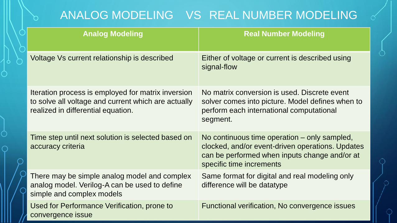
ANALOG MODELING VS REAL NUMBER MODELING
Analog Modeling Real Number Modeling
Voltage Vs current relationship is described Either of voltage or current is described using
signal-flow
Iteration process is employed for matrix inversion
to solve all voltage and current which are actually
realized in differential equation.
No matrix conversion is used. Discrete event
solver comes into picture. Model defines when to
perform each international computational
segment.
Time step until next solution is selected based on
accuracy criteria
No continuous time operation – only sampled,
clocked, and/or event-driven operations. Updates
can be performed when inputs change and/or at
specific time increments
There may be simple analog model and complex
analog model. Verilog-A can be used to define
simple and complex models
Same format for digital and real modeling only
difference will be datatype
Used for Performance Verification, prone to
convergence issue
Functional verification, No convergence issues

FEATURES OF DIFFERENT MODELING STYLES
Verilog Verilog-AMS Analog Verilog-vams wreal SV-RNM
Faster than Spice Faster than Spice
Faster than Spice Faster than Spice
Digital solver only Electrical signals
(voltage, current)
Digital solver only Digital solver only
No real ports
($bitstoreal /
$realtobits)
Requires analog
solver
Real ports Multi-value nets
(UDT/UDR)
Convergence errors Single-value nets
(voltage or current)
SV constructs
and verification
techniques
No SystemVerilog
constructs
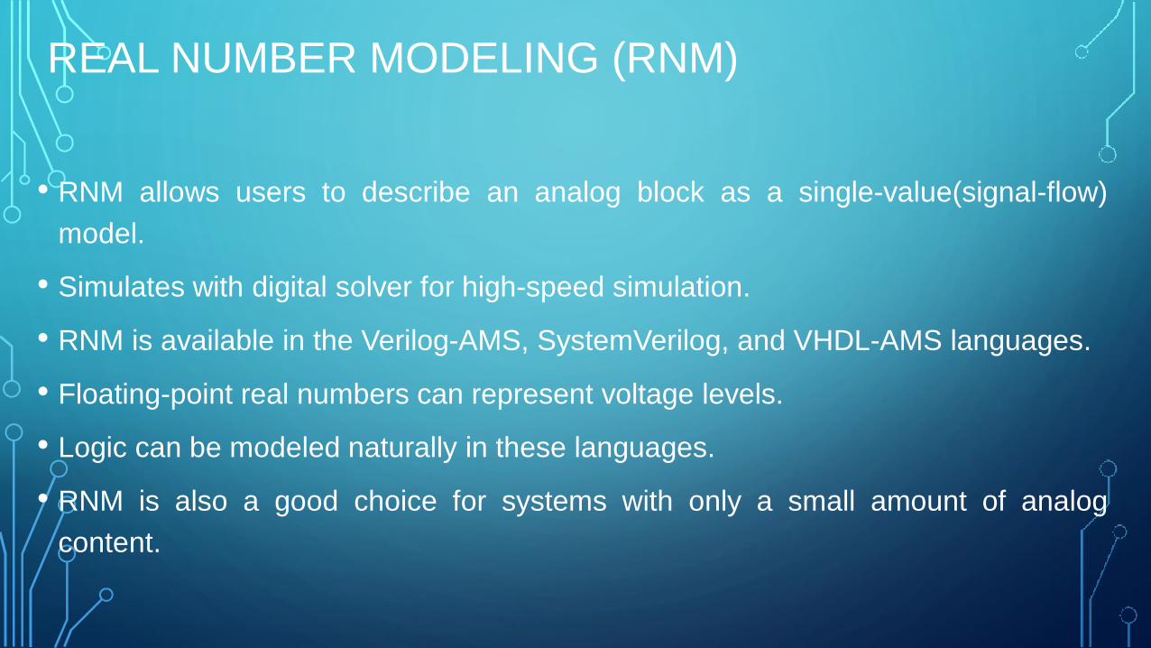
REAL NUMBER MODELING (RNM)
• RNM allows users to describe an analog block as a single-value(signal-flow)
model.
• Simulates with digital solver for high-speed simulation.
• RNM is available in the Verilog-AMS, SystemVerilog, and VHDL-AMS languages.
• Floating-point real numbers can represent voltage levels.
• Logic can be modeled naturally in these languages.
• RNM is also a good choice for systems with only a small amount of analog
content.
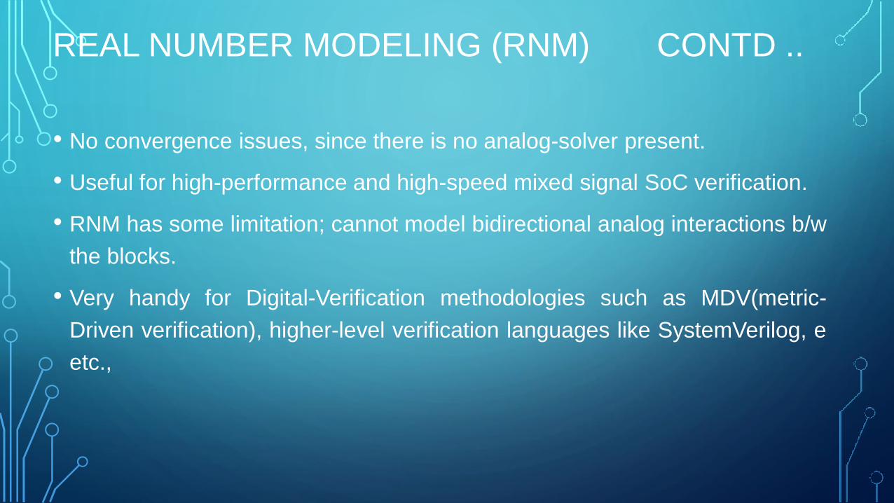
REAL NUMBER MODELING (RNM) CONTD ..
• No convergence issues, since there is no analog-solver present.
• Useful for high-performance and high-speed mixed signal SoC verification.
• RNM has some limitation; cannot model bidirectional analog interactions b/w
the blocks.
• Very handy for Digital-Verification methodologies such as MDV(metric-
Driven verification), higher-level verification languages like SystemVerilog, e
etc.,
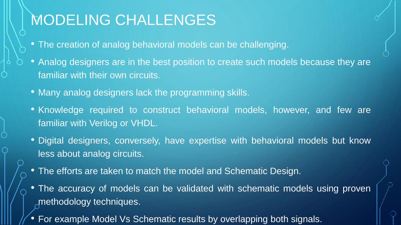
MODELING CHALLENGES
• The creation of analog behavioral models can be challenging.
• Analog designers are in the best position to create such models because they are
familiar with their own circuits.
• Many analog designers lack the programming skills.
• Knowledge required to construct behavioral models, however, and few are
familiar with Verilog or VHDL.
• Digital designers, conversely, have expertise with behavioral models but know
less about analog circuits.
• The efforts are taken to match the model and Schematic Design.
• The accuracy of models can be validated with schematic models using proven
methodology techniques.
• For example Model Vs Schematic results by overlapping both signals.
• Manually checking both the model results.
• Assertions on both the model boundaries.
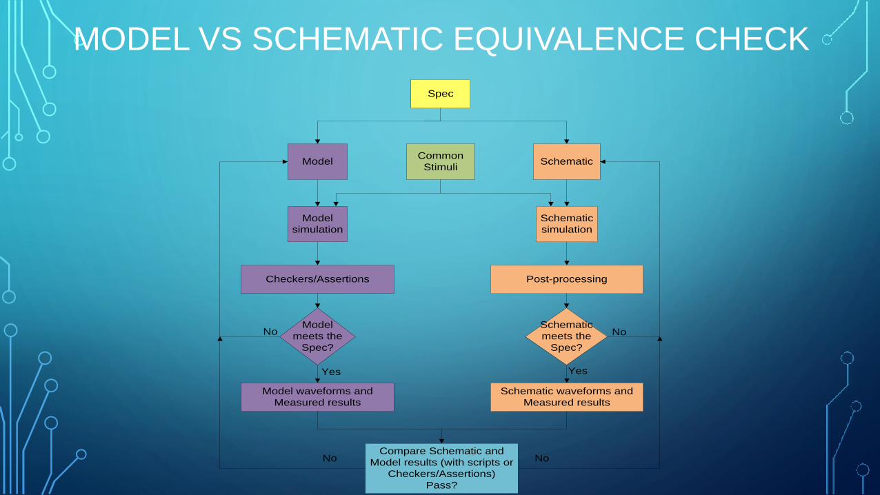
Model
Spec
Checkers/Assertions
Model
simulation
Model
meets the
Spec?
Model waveforms and
Measured results
Schematic
Schematic
simulation
Post-processing
Schematic
meets the
Spec?
Schematic waveforms and
Measured results
Common
Stimuli
No
Compare Schematic and
Model results (with scripts or
Checkers/Assertions)
Pass?
No
Yes Yes
No No
MODEL VS SCHEMATIC EQUIVALENCE CHECK
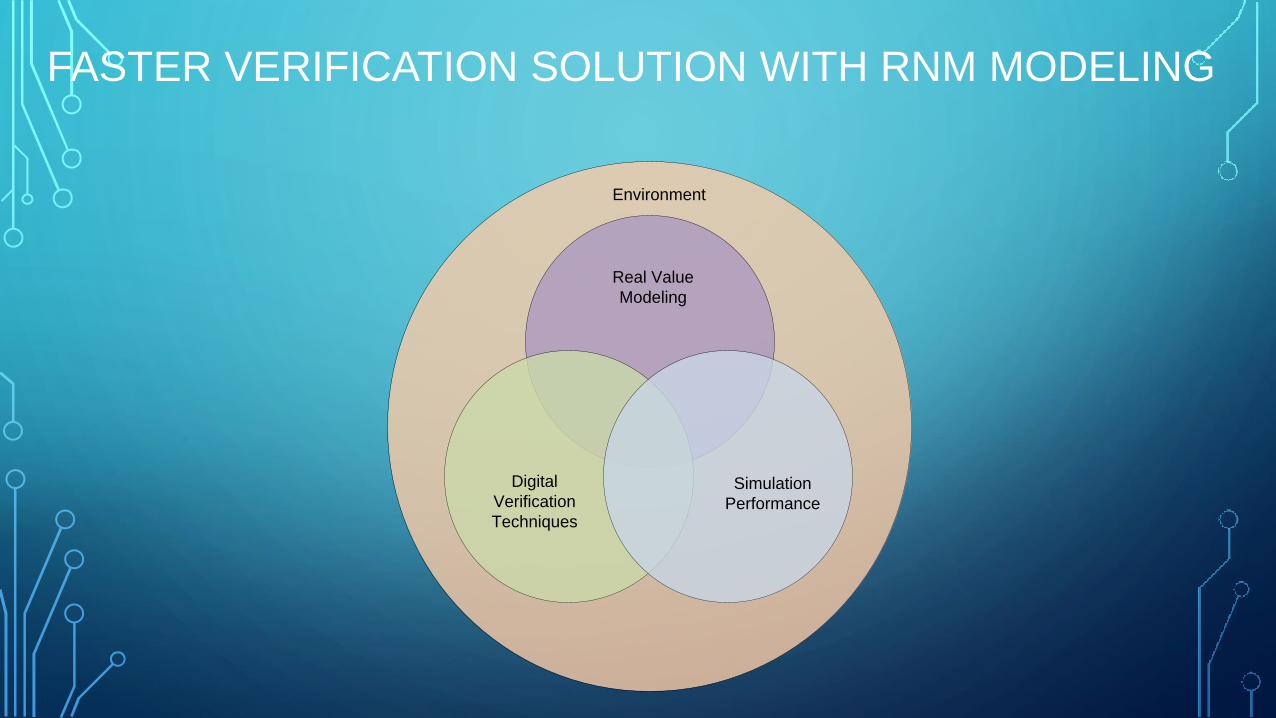
Real Value
Modeling
Digital
Verification
Techniques
Simulation
Performance
Environment
FASTER VERIFICATION SOLUTION WITH RNM MODELING
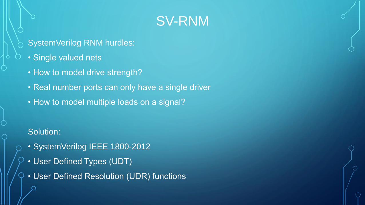
SV-RNM
SystemVerilog RNM hurdles:
• Single valued nets
• How to model drive strength?
• Real number ports can only have a single driver
• How to model multiple loads on a signal?
Solution:
• SystemVerilog IEEE 1800-2012
• User Defined Types (UDT)
• User Defined Resolution (UDR) functions
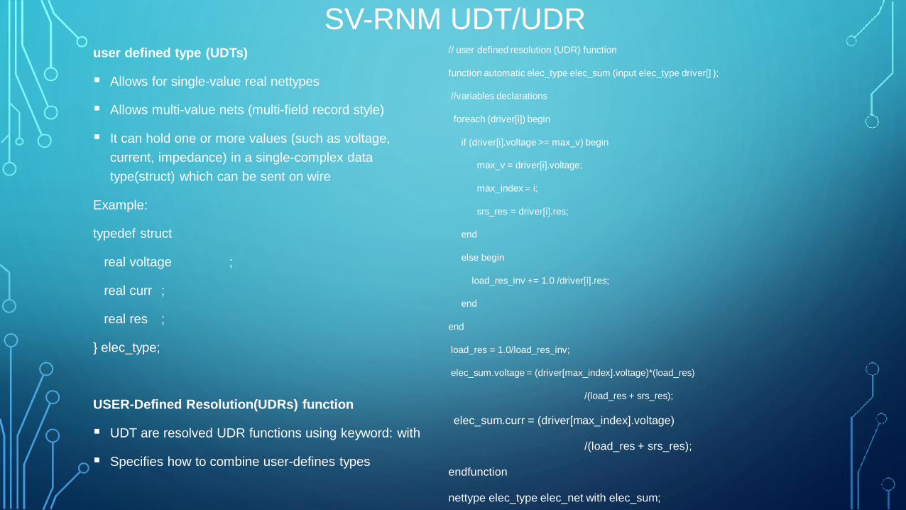
SV-RNM UDT/UDR user defined type (UDTs)
Allows for single-value real nettypes
Allows multi-value nets (multi-field record style)
It can hold one or more values (such as voltage,
current, impedance) in a single-complex data
type(struct) which can be sent on wire
Example:
typedef struct
real voltage ;
real curr ;
real res ;
} elec_type;
USER-Defined Resolution(UDRs) function
UDT are resolved UDR functions using keyword: with
Specifies how to combine user-defines types
// user defined resolution (UDR) function
function automatic elec_type elec_sum (input elec_type driver[] );
//variables declarations
foreach (driver[i]) begin
if (driver[i].voltage >= max_v) begin
max_v = driver[i].voltage;
max_index = i;
srs_res = driver[i].res;
end
else begin
load_res_inv += 1.0 /driver[i].res;
end
end
load_res = 1.0/load_res_inv;
elec_sum.voltage = (driver[max_index].voltage)*(load_res)
/(load_res + srs_res);
elec_sum.curr = (driver[max_index].voltage)
/(load_res + srs_res);
endfunction
nettype elec_type elec_net with elec_sum;

SV-RNM FUNCTIONAL COVERAGE, RANDOMIZATION
//cover group transaction
Covergroup real vbat_cg
option.range_precision = 0.1;
vbat_voltage : coverpoint vbat_r {
bins A_0mV_to_800mV = {[$:0.8]};
bins A_800mV_to_3V = {[0.8:3.0]};
bins A_3V_to_4V = {[3.0:4]};
illegal_bins A_above_4V = {[4:10.0]};
}
//cover group transaction
Covergroup real vref_cg
option.range_precision = 0.1;
vref_voltage : coverpoint vref_r {
bins A_0mV_to_500mV = {[$:0.5]};
bins A_500mV_to_1V = {[0.5:1.0]};
bins A_1V_to_1.3V = {[1.0:1.3]};
illegal_bins A_above_1.3V = {[1.3:2.0]};
}
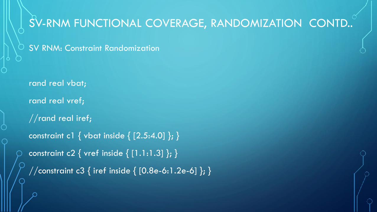
SV-RNM FUNCTIONAL COVERAGE, RANDOMIZATION CONTD..
SV RNM: Constraint Randomization
rand real vbat;
rand real vref;
//rand real iref;
constraint c1 { vbat inside { [2.5:4.0] }; }
constraint c2 { vref inside { [1.1:1.3] }; }
//constraint c3 { iref inside { [0.8e-6:1.2e-6] }; }

SV-RNM ASSERTIONS , CHECKERS
always @( en) begin
assert_vbat_range:
assert ((2.5 <= vbat.voltage) && (vbat.voltage <= 4.0) ) else
$display("ERROR: vbat not in range");
end
always @(en) begin
assert_vreg_1v8_range:
assert ((1.7 <= vreg_1v8.voltage) && (vreg_1v8.voltage <= 1.9)) else
$display("ERROR: vreg_1v8 output is out of range:%0.2fV", vreg_1v8.voltage);
end
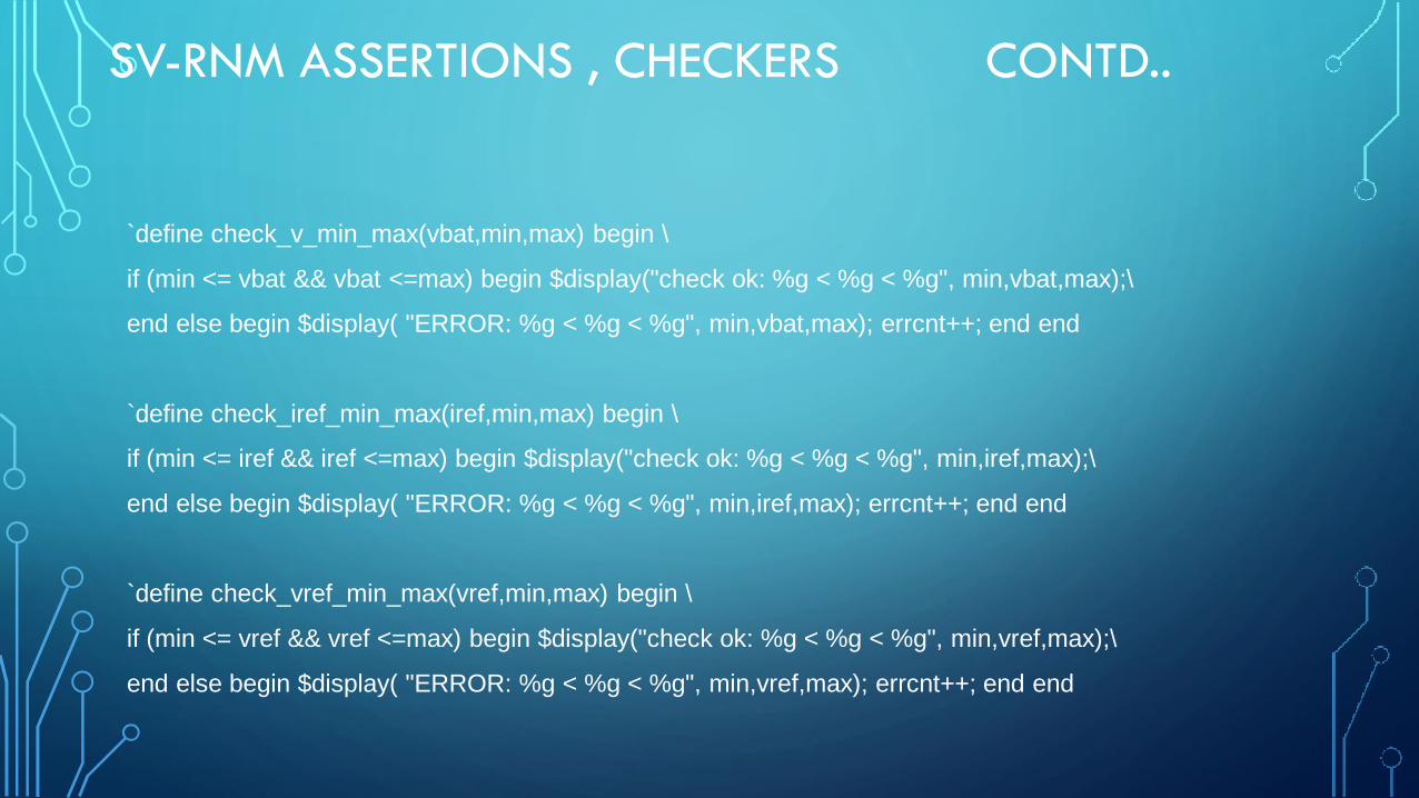
SV-RNM ASSERTIONS , CHECKERS CONTD..
`define check_v_min_max(vbat,min,max) begin \
if (min <= vbat && vbat <=max) begin $display("check ok: %g < %g < %g", min,vbat,max);\
end else begin $display( "ERROR: %g < %g < %g", min,vbat,max); errcnt++; end end
`define check_iref_min_max(iref,min,max) begin \
if (min <= iref && iref <=max) begin $display("check ok: %g < %g < %g", min,iref,max);\
end else begin $display( "ERROR: %g < %g < %g", min,iref,max); errcnt++; end end
`define check_vref_min_max(vref,min,max) begin \
if (min <= vref && vref <=max) begin $display("check ok: %g < %g < %g", min,vref,max);\
end else begin $display( "ERROR: %g < %g < %g", min,vref,max); errcnt++; end end
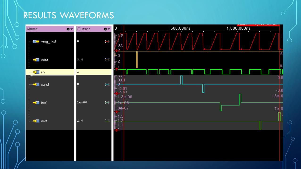
RESULTS WAVEFORMS
CONCLUSION
• Lesser Simulation time
• Non Requirement of Analog solver
• Accurate sub-system and full chip simulations
• Efficient digital license utilization
• Use of Constraint randomization

Thank you