Embed Size (px)
Citation preview
Real-World Automation: New Capabilities for Underground LongwallMining
Peter B Reid, Mark T Dunn, David C Reid and Jonathon C RalstonCSIRO Mining Technology
Queensland Centre for Advanced TechnologiesPullenvale, Qld 4069 Australia
Abstract
This paper describes successful industrial re-search and development in the area of under-ground coal mining equipment automation. Abrief background to underground coal mining isgiven, and the process of longwall mining is de-tailed. Some of the major limitations and issuesimpacting on the productivity and safety of thelongwall mining process are highlighted, whichserve to motivate the automation development.The solution developed integrates high perfor-mance inertial navigation, signal processing,communications and control technology to de-liver a robust, production grade automationsystem. The benefits of this automation systemhave been recognised and strongly adopted bythe Australian mining industry.
1 Introduction
The underground coal mining industry is constantlydriven by the need to improve mining productivity, in-crease personnel safety, and secure environmental sus-tainability. Mining automation technology has shownsignificant potential to meet these needs by providingmore accurate mining methods, supporting predictivemaintenance, delivering hazard monitoring systems, in-corporating sensing to optimally control equipment andincreasing personnel safety through remote process op-eration.
This paper describes the key research technology out-comes of a ten year research project referred to as LASCTechnology1. The success of the research is evidentthrough the strong industry adoption and utilisation atmultiple Australian longwall sites [LASC, 2010]. LASCTechnology is now being supplied by all the major long-wall equipment manufacturers under international li-
1Longwall Automation Steering Committee (LASC) –http://www.lascautomation.org/
censing agreements with the Commonwealth Scientificand Industrial Research Organisation (CSIRO).
2 The Longwall Mining Process
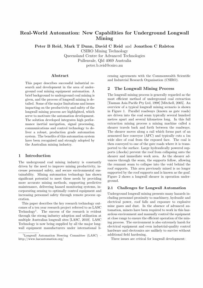
The longwall mining process is generally regarded as themost efficient method of underground coal extraction[Tasman Asia Pacific Pty Ltd, 1998] [Mitchell, 2005]. Anoverview of a typical longwall mining scenario is shownin Figure 1. Parallel roadways (known as gate roads)are driven into the coal seam typically several hundredmetres apart and several kilometres long. In this fullextraction mining process a mining machine called ashearer travels back and forth between the roadways.The shearer moves along a rail which forms part of anarmoured face conveyor (AFC) and typically cuts a 1mwide slice of coal from the exposed face. The coal isthen conveyed to one of the gate roads where it is trans-ported to the surface. Large hydraulically powered sup-ports (chocks) prevent the roof from collapsing onto theshearer and immediate work area. As the shearer ad-vances through the seam, the supports follow, allowingthe remnant seam to collapse into the void behind theroof supports. This area previously mined is no longersupported by the roof supports and is known as the goaf.Figure 2 shows a longwall shearer in operation under-ground.
2.1 Challenges for Longwall Automation
Underground longwall mining presents many hazards in-cluding personnel proximity to machinery, hydraulic andelectrical power, roof falls and exposure to explosivemine gases and dust. In the absence of advanced au-tomation, miners have been required to work in this haz-ardous environment and manually control the equipmentat close range to ensure the efficient operation of the min-ing process. The environment is also extremely harsh forelectrical equipment and even industrial-quality controlhardware and electronics are unlikely to survive withoutadditional field hardening.Three issues are critical for longwall development:
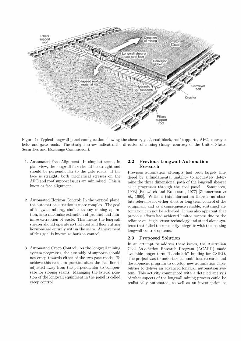
Figure 1: Typical longwall panel configuration showing the shearer, goaf, coal block, roof supports, AFC, conveyorbelts and gate roads. The straight arrow indicates the direction of mining (Image courtesy of the United StatesSecurities and Exchange Commission).
1. Automated Face Alignment: In simplest terms, inplan view, the longwall face should be straight andshould be perpendicular to the gate roads. If theface is straight, both mechanical stresses on theAFC and roof support issues are minimised. This isknow as face alignment.
2. Automated Horizon Control: In the vertical plane,the automation situation is more complex. The goalof longwall mining, similar to any mining opera-tion, is to maximise extraction of product and min-imise extraction of waste. This means the longwallshearer should operate so that roof and floor cuttinghorizons are entirely within the seam. Achievementof this goal is known as horizon control.
3. Automated Creep Control: As the longwall miningsystem progresses, the assembly of supports shouldnot creep towards either of the two gate roads. Toachieve this result in practice often the face line isadjusted away from the perpendicular to compen-sate for sloping seams. Managing the lateral posi-tion of the longwall equipment in the panel is calledcreep control.
2.2 Previous Longwall AutomationResearch
Previous automation attempts had been largely hin-dered by a fundamental inability to accurately deter-mine the three dimensional path of the longwall sheareras it progresses through the coal panel. [Sammarco,1993] [Palowitch and Broussard, 1977] [Zimmerman etal., 1998]. Without this information there is no abso-lute reference for either short or long term control of theequipment and as a consequence reliable, sustained au-tomation can not be achieved. It was also apparent thatprevious efforts had achieved limited success due to thereliance on single sensor technology and stand alone sys-tems that failed to sufficiently integrate with the existinglongwall control systems.
2.3 Proposed Solution
In an attempt to address these issues, the AustralianCoal Association Research Program (ACARP) madeavailable longer term “Landmark” funding for CSIRO.The project was to undertake an ambitious research anddevelopment program to develop new automation capa-bilities to deliver an advanced longwall automation sys-tem. This activity commenced with a detailed analysisof what aspects of the longwall mining process could berealistically automated, as well as an investigation as
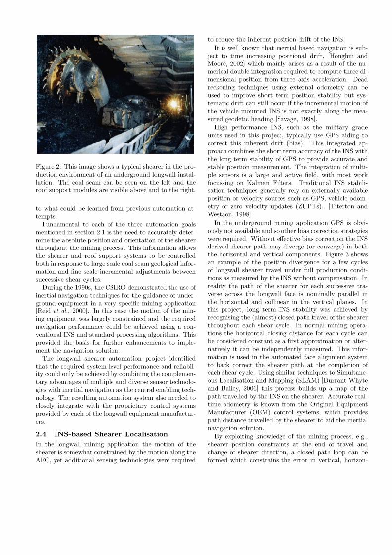
Figure 2: This image shows a typical shearer in the pro-duction environment of an underground longwall instal-lation. The coal seam can be seen on the left and theroof support modules are visible above and to the right.
to what could be learned from previous automation at-tempts.Fundamental to each of the three automation goals
mentioned in section 2.1 is the need to accurately deter-mine the absolute position and orientation of the shearerthroughout the mining process. This information allowsthe shearer and roof support systems to be controlledboth in response to large scale coal seam geological infor-mation and fine scale incremental adjustments betweensuccessive shear cycles.During the 1990s, the CSIRO demonstrated the use of
inertial navigation techniques for the guidance of under-ground equipment in a very specific mining application[Reid et al., 2000]. In this case the motion of the min-ing equipment was largely constrained and the requirednavigation performance could be achieved using a con-ventional INS and standard processing algorithms. Thisprovided the basis for further enhancements to imple-ment the navigation solution.The longwall shearer automation project identified
that the required system level performance and reliabil-ity could only be achieved by combining the complemen-tary advantages of multiple and diverse sensor technolo-gies with inertial navigation as the central enabling tech-nology. The resulting automation system also needed toclosely integrate with the proprietary control systemsprovided by each of the longwall equipment manufactur-ers.
2.4 INS-based Shearer Localisation
In the longwall mining application the motion of theshearer is somewhat constrained by the motion along theAFC, yet additional sensing technologies were required
to reduce the inherent position drift of the INS.
It is well known that inertial based navigation is sub-ject to time increasing positional drift, [Honghui andMoore, 2002] which mainly arises as a result of the nu-merical double integration required to compute three di-mensional position from three axis acceleration. Deadreckoning techniques using external odometry can beused to improve short term position stability but sys-tematic drift can still occur if the incremental motion ofthe vehicle mounted INS is not exactly along the mea-sured geodetic heading [Savage, 1998].
High performance INS, such as the military gradeunits used in this project, typically use GPS aiding tocorrect this inherent drift (bias). This integrated ap-proach combines the short term accuracy of the INS withthe long term stability of GPS to provide accurate andstable position measurement. The integration of multi-ple sensors is a large and active field, with most workfocussing on Kalman Filters. Traditional INS stabili-sation techniques generally rely on externally availableposition or velocity sources such as GPS, vehicle odom-etry or zero velocity updates (ZUPTs). [Titerton andWestaon, 1998]
In the underground mining application GPS is obvi-ously not available and so other bias correction strategieswere required. Without effective bias correction the INSderived shearer path may diverge (or converge) in boththe horizontal and vertical components. Figure 3 showsan example of the position divergence for a few cyclesof longwall shearer travel under full production condi-tions as measured by the INS without compensation. Inreality the path of the shearer for each successive tra-verse across the longwall face is nominally parallel inthe horizontal and collinear in the vertical planes. Inthis project, long term INS stability was achieved byrecognising the (almost) closed path travel of the shearerthroughout each shear cycle. In normal mining opera-tions the horizontal closing distance for each cycle canbe considered constant as a first approximation or alter-natively it can be independently measured. This infor-mation is used in the automated face alignment systemto back correct the shearer path at the completion ofeach shear cycle. Using similar techniques to Simultane-ous Localisation and Mapping (SLAM) [Durrant-Whyteand Bailey, 2006] this process builds up a map of thepath travelled by the INS on the shearer. Accurate real-time odometry is known from the Original EquipmentManufacturer (OEM) control systems, which providespath distance travelled by the shearer to aid the inertialnavigation solution.
By exploiting knowledge of the mining process, e.g.,shearer position constraints at the end of travel andchange of shearer direction, a closed path loop can beformed which constrains the error in vertical, horizon-
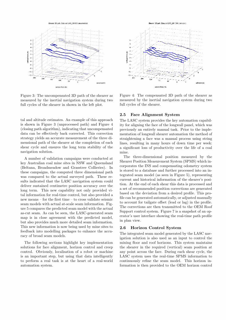
Figure 3: The uncompensated 3D path of the shearer asmeasured by the inertial navigation system during twofull cycles of the shearer in shown in the left plot.
tal and altitude estimates. An example of this approachis shown in Figure 3 (unprocessed path) and Figure 4(closing path algorithm), indicating that uncompensateddata can be effectively back corrected. This correctionstrategy yields an accurate measurement of the three di-mensional path of the shearer at the completion of eachshear cycle and ensures the long term stability of thenavigation solution.
A number of validation campaigns were conducted atkey Australian coal mine sites in NSW and Queensland(Beltana, Broadmeadow and Grasstree Collieries). Inthese campaigns, the computed three dimensional pathwas compared to the actual surveyed path. These re-sults indicated that the LASC navigation system coulddeliver sustained centimetre position accuracy over thelong term. This new capability not only provided vi-tal information for real-time control, but also provided anew means – for the first time – to cross validate seismicseam models with actual at-scale seam information. Fig-ure 5 compares the predicted seam model with the actualas-cut seam. As can be seen, the LASC-generated seammap is in close agreement with the predicted model,but also provides much more detailed seam information.This new information is now being used by mine sites tofeedback into modelling packages to enhance the accu-racy of broad seam models.
The following sections highlight key implementationsolutions for face alignment, horizon control and creepcontrol. Obviously, localisation of a robot or machineis an important step, but using that data intelligentlyto perform a real task is at the heart of a real-worldautomation system.
Figure 4: The compensated 3D path of the shearer asmeasured by the inertial navigation system during twofull cycles of the shearer.
2.5 Face Alignment System
The LASC system provides the key automation capabil-ity for aligning the face of the longwall panel, which waspreviously an entirely manual task. Prior to the imple-mentation of longwall shearer automation the method ofstraightening a face was a manual process using stringlines, resulting in many hours of down time per week:a significant loss of productivity over the life of a coalmine.The three-dimensional position measured by the
Shearer Position Measurement System (SPMS) which in-corporates the INS and compensating odometry systemis stored to a database and further processed into an in-tegrated seam model (as seen in Figure 5), representingcurrent and historical information of the shearer’s posi-tion. At the end of each shear this data is processed anda set of recommended position corrections are generatedbased on the deviation from a desired profile. This pro-file can be generated automatically, or adjusted manuallyto account for tailgate offset (lead or lag) in the profile.The corrections are then transmitted to the OEM RoofSupport control system. Figure 7 is a snapshot of an op-erator’s user interface showing the real-time path profilein plan view.
2.6 Horizon Control System
The integrated seam model generated by the LASC nav-igation solution is also used as an input to control themining floor and roof horizons. This system maintainsthe shearer in the required (vertical) seam position atany point across the face. During each shear cycle, theLASC system uses the real-time SPMS information tocontinuously refine the seam model. This horizon in-formation is then provided to the OEM horizon control
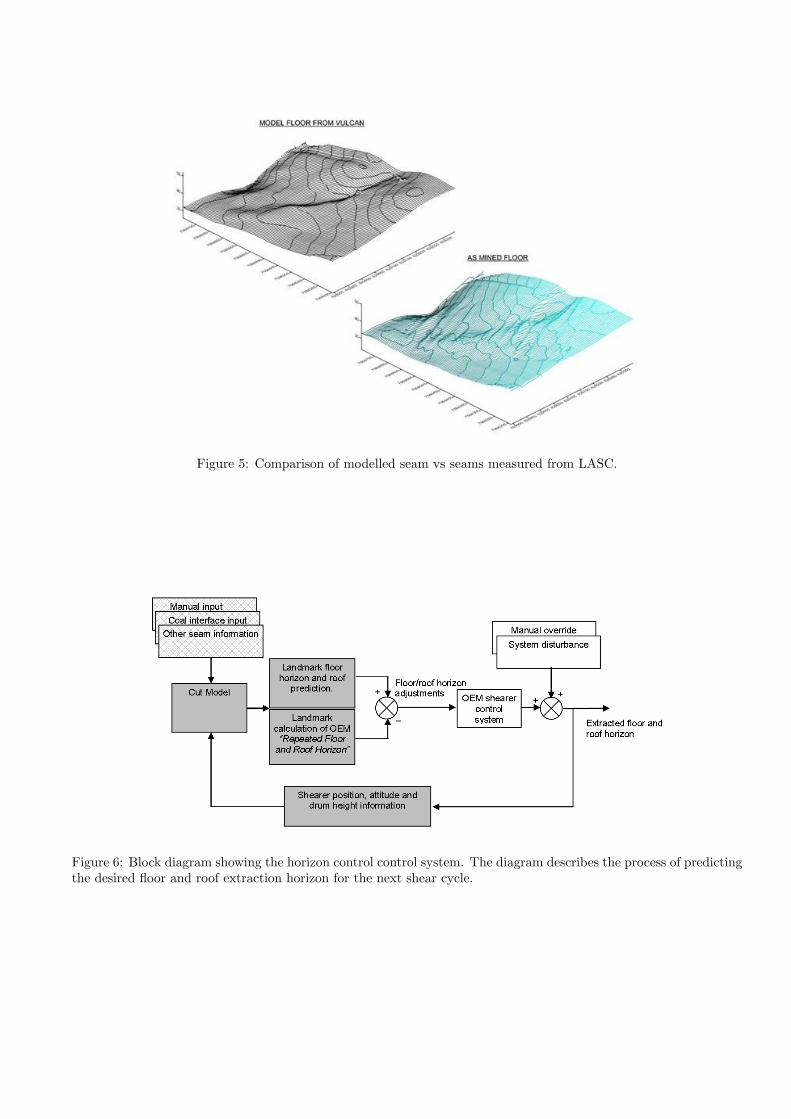
Figure 5: Comparison of modelled seam vs seams measured from LASC.
Figure 6: Block diagram showing the horizon control control system. The diagram describes the process of predictingthe desired floor and roof extraction horizon for the next shear cycle.
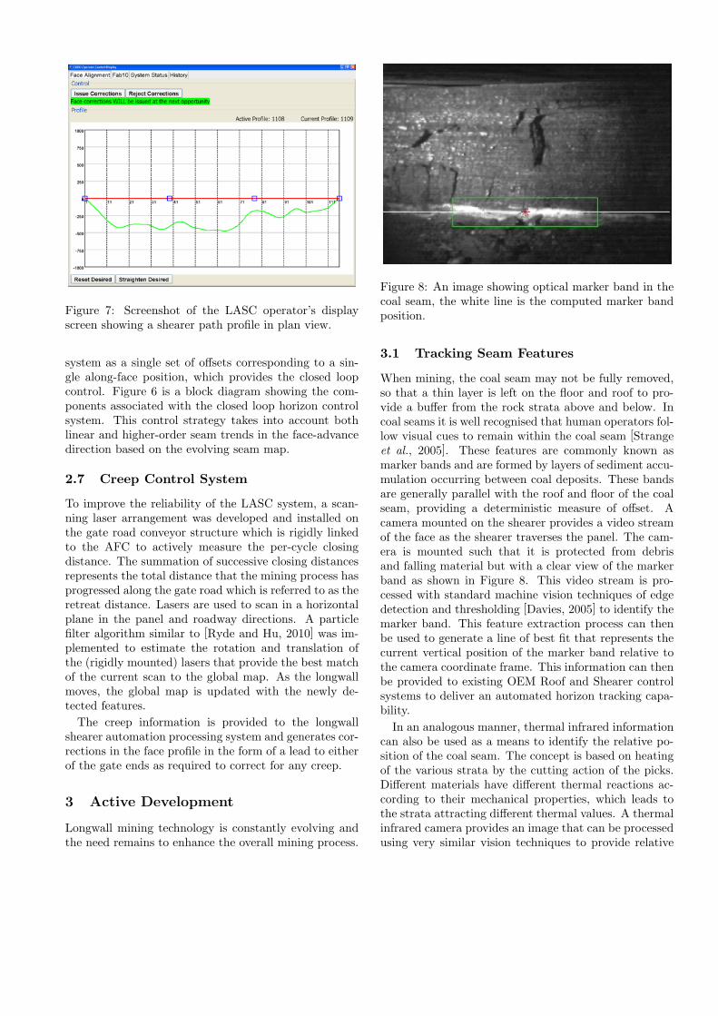
Figure 7: Screenshot of the LASC operator’s displayscreen showing a shearer path profile in plan view.
system as a single set of offsets corresponding to a sin-gle along-face position, which provides the closed loopcontrol. Figure 6 is a block diagram showing the com-ponents associated with the closed loop horizon controlsystem. This control strategy takes into account bothlinear and higher-order seam trends in the face-advancedirection based on the evolving seam map.
2.7 Creep Control System
To improve the reliability of the LASC system, a scan-ning laser arrangement was developed and installed onthe gate road conveyor structure which is rigidly linkedto the AFC to actively measure the per-cycle closingdistance. The summation of successive closing distancesrepresents the total distance that the mining process hasprogressed along the gate road which is referred to as theretreat distance. Lasers are used to scan in a horizontalplane in the panel and roadway directions. A particlefilter algorithm similar to [Ryde and Hu, 2010] was im-plemented to estimate the rotation and translation ofthe (rigidly mounted) lasers that provide the best matchof the current scan to the global map. As the longwallmoves, the global map is updated with the newly de-tected features.
The creep information is provided to the longwallshearer automation processing system and generates cor-rections in the face profile in the form of a lead to eitherof the gate ends as required to correct for any creep.
3 Active Development
Longwall mining technology is constantly evolving andthe need remains to enhance the overall mining process.
Figure 8: An image showing optical marker band in thecoal seam, the white line is the computed marker bandposition.
3.1 Tracking Seam Features
When mining, the coal seam may not be fully removed,so that a thin layer is left on the floor and roof to pro-vide a buffer from the rock strata above and below. Incoal seams it is well recognised that human operators fol-low visual cues to remain within the coal seam [Strangeet al., 2005]. These features are commonly known asmarker bands and are formed by layers of sediment accu-mulation occurring between coal deposits. These bandsare generally parallel with the roof and floor of the coalseam, providing a deterministic measure of offset. Acamera mounted on the shearer provides a video streamof the face as the shearer traverses the panel. The cam-era is mounted such that it is protected from debrisand falling material but with a clear view of the markerband as shown in Figure 8. This video stream is pro-cessed with standard machine vision techniques of edgedetection and thresholding [Davies, 2005] to identify themarker band. This feature extraction process can thenbe used to generate a line of best fit that represents thecurrent vertical position of the marker band relative tothe camera coordinate frame. This information can thenbe provided to existing OEM Roof and Shearer controlsystems to deliver an automated horizon tracking capa-bility.
In an analogous manner, thermal infrared informationcan also be used as a means to identify the relative po-sition of the coal seam. The concept is based on heatingof the various strata by the cutting action of the picks.Different materials have different thermal reactions ac-cording to their mechanical properties, which leads tothe strata attracting different thermal values. A thermalinfrared camera provides an image that can be processedusing very similar vision techniques to provide relative
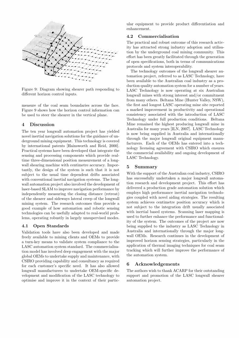
Figure 9: Diagram showing shearer path responding todifferent horizon control inputs.
measure of the coal seam boundaries across the face.Figure 9 shows how the horizon control information canbe used to steer the shearer in the vertical plane.
4 Discussion
The ten year longwall automation project has yieldednovel inertial navigation solutions for the guidance of un-derground mining equipment. This technology is coveredby international patents [Hainsworth and Reid, 2000].Practical systems have been developed that integrate thesensing and processing components which provide real-time three-dimensional position measurement of a long-wall shearing machine with centimetre accuracy. Impor-tantly, the design of the system is such that it is notsubject to the usual time dependent drifts associatedwith conventional inertial navigation systems. The long-wall automation project also involved the development oflaser-based SLAM to improve navigation performance byindependently measuring the closing distance (retreat)of the shearer and sideways lateral creep of the longwallmining system. The research outcomes thus provide agood example of how automation and robotic sensingtechnologies can be usefully adapted to real-world prob-lems, operating robustly in largely unsupervised modes.
4.1 Open Standards
Validation tools have also been developed and madefreely available to mining clients and OEMs to providea turn-key means to validate system compliance to theLASC automation system standard. The commercialisa-tion model has involved deep engagement with the majorglobal OEMs to undertake supply and maintenance, withCSIRO providing capability and consultancy as requiredfor each customer’s specific need. It has also allowedlongwall manufacturers to undertake OEM-specific de-velopment and modification of the LASC technology tooptimise and improve it in the context of their partic-
ular equipment to provide product differentiation andenhancement.
4.2 Commercialisation
The practical and robust outcome of this research activ-ity has attracted strong industry adoption and utilisa-tion by the underground coal mining community. Thiseffort has been greatly facilitated through the generationof open specifications, both in terms of communicationsprotocols and system interoperability.The technology outcomes of the longwall shearer au-
tomation project, referred to as LASC Technology, havebeen available to the Australian coal industry as a pro-duction quality automation system for a number of years.LASC Technology is now operating at six Australianlongwall mines with strong interest and/or commitmentfrom many others. Beltana Mine (Hunter Valley, NSW),the first and longest LASC operating mine site reporteda marked improvement in productivity and operationalconsistency associated with the introduction of LASCTechnology under full production conditions. BeltanaMine remained the highest producing longwall mine inAustralia for many years [ILN, 2007]. LASC Technologyis now being supplied in Australia and internationallythrough the major longwall original equipment manu-facturers. Each of the OEMs has entered into a tech-nology licensing agreement with CSIRO which ensuresthe commercial availability and ongoing development ofLASC Technology.
5 Summary
With the support of the Australian coal industry, CSIROhas successfully undertaken a major longwall automa-tion research and development project. This effort hasdelivered a production grade automation solution whichemploys high performance inertial navigation technolo-gies coupled with novel aiding strategies. The resultingsystem achieves centimetre position accuracy which isnot subject to the integration drift usually associatedwith inertial based systems. Scanning laser mapping isused to further enhance the performance and functional-ity of the system. The outcomes of the project are nowbeing supplied to the industry as LASC Technology inAustralia and internationally through the major long-wall OEMs. Research continues in the development ofimproved horizon sensing strategies, particularly in theapplication of thermal imaging techniques for coal seamtracking which will further improve the performance ofthe automation system.
6 Acknowledgements
The authors wish to thank ACARP for their outstandingsupport and promotion of the LASC longwall shearerautomation project.
References[CSIRO, 2005] Exploration & Mining Report P2005/75
Interconnection of Landmark Compliant LongwallMining Equipment - Shearer Communication Speci-fication for OEM Accessible Data.
[Davies, 2005] Machine Vision: Theory, Algorithms,Practicalities 3rd ed., Amsterdam, Boston
[Durrant-Whyte and Bailey, 2006] Simultaneous locali-sation and mapping (SLAM): Part I the essential al-gorithms Robot. Autom. Mag, vol. 13, pp 99-110. Jun.2006
[Hainsworth, 1997] D. W. Hainsworth Automatic Hori-zon Control of Coal Mining Machinery in Proceedingsof the 4th International Symposium on Mine Mecha-nisation and Automation, 1997, pp B6:11-19, (Bris-bane).
[Hainsworth and Reid, 2000] D. W. Hainsworth and D.C. Reid Mining Machine and Method, AustralianPatent PQ7131, April 26, 2000 and US Patent, May12, 2000.
[Honghui and Moore, 2002] Direct Kalman filtering ap-proach for GPS/INS integration Aerospace and Elec-tronic Systems, IEEE Transactions on, vol. 38, no. 2,pp 687-693.
[ILN, 2007] International Longwall News AspermontLimited, Leaderville, Western Australia.
[LASC, 2010] Longwall Automation Steering Commit-tee (LASC), http://www.lascautomation.org
[Mitchell, 2005] Longwall Mining Australasian CoalMining Practice, ch. 15, pp 340-375.
[Reid et al., 1997] D. C. Reid, D. W. Hainsworth, R. J.McPhee Lateral guidance of highwall mining machin-ery using inertial navigation Proceedings of the 4thInternational Symposium on Mine Mechanisation andAutomation, 1997, pp B6:1-10 (Brisbane).
[Reid et al., 2000] D. C. Reid, J. C. Ralston, D. W.Hainsworth, R. J. McPhee and E. Matejowsky High-wall Mining Guidance: A Major Advance in High-wall Mining Teleoperation 1st International Workshopon Advances in Robotics for Mining and UndergroundApplications, Brisbane Australia, Oct 2-4, 2000.
[Palowitch and Broussard, 1977] Some opportunities inteleoperated mining Mechanism and Machine Theory,vol. 12, pp. 493-501, 1977.
[Reid et al., 2001] D. C. Reid, D. W. Hainsworth, J. C.Ralston, R. J. McPhee Longwall shearer guidanceusing inertial navigation (ACARP project C9015),CSIRO, Exploration and Mining Report 832F.
[Ryde and Hu, 2010]
3D Mapping with Multi-Resolution Occupied Voxel
Lists Autonomous Robots, Springer Netherlands, vol.28, pp. 169-185, 2010
[Sammarco, 1993] J. J. Sammarco Field Evaluationof the Modular Azimuth and Positioning System(MAPS) for a Continuous Mining Machine Bureauof Mines Information Circular 9354, pp. 1-14.
[Savage, 1998] Strapdown Inertial Navigation Integra-tion Algorithm Design. Part 1: Attitude AlgorithmsJournal of guidance, control, and dynamics, vol. 21,no. 1, pp. 19-28
[Strange et al., 2005] Strange, Andrew and Ralston,Jonathon and Chandran, Vinod Near-surface Inter-face Detection for Coal Mining Applications using Bis-pectral Features and GPR Sensing and Imaging: AnInternational Journal, Springer New York vol. 6, no.2, pp. 125-149, 2005
[Tasman Asia Pacific Pty Ltd, 1998] Bench-marking The Productivity of Australia’s Black CoalIndustry http://http://www.pc.gov.au/.
[Titerton and Westaon, 1998] Strapdown Inertial Navi-gation Technology, 2nd Edition Progress in Astronau-tics and Aeronautics Series, Published by AIAA.
[Zimmerman et al., 1998] W. A. Zimmerman, R. W.;Harris, J.; High, J. Automation of the longwall miningsystem NASA Jet Propulsion Laboratory1, November,1982


![Closed Captioning in Games ● Reid Kimball ● Games[CC] ● reid@rbkdesign.com reid@rbkdesign.com ●](https://img.pdfslide.net/doc/110x75/56649e565503460f94b4e219/closed-captioning-in-games-reid-kimball-gamescc-reidrbkdesigncom.jpg)