Embed Size (px)
Citation preview
I n s ta l l at I o n , s ta r t - U p a n d o p e r at I o n o f l o a d M at c h ® s y s t e M s
Installation Instructions
www.taco-hvac.com
Real world hydronic system technology for Green Building design.
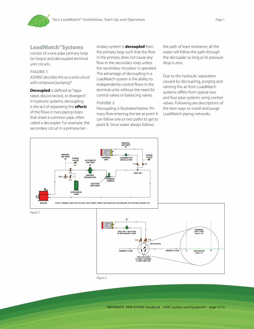
LoadMatch®Systems consist of a one pipe primary loop (or loops) and decoupled terminal unit circuits.
FIgure 1 ASHRAE describes this as a series circuit with compound pumping*.
decoupled is defined as “sepa-rated, disconnected, or divergent”. In hydronic systems, decoupling is the act of separating the effects of the flows in two piping loops that share a common pipe, often called a decoupler. For example, the secondary circuit in a primary/sec-
ondary system is decoupled from the primary loop such that the flow in the primary does not cause any flow in the secondary loop unless the secondary circulator is operated. The advantage of decoupling in a LoadMatch system is the ability to independently control flows in the terminal units without the need for control valves or balancing valves.
FIgure 2 Decoupling is illustrated below. Pri-mary flow entering the tee at point A can follow one or two paths to get to point B. Since water always follows
the path of least resistance, all the water will follow the path through the decoupler as long as its pressure drop is zero.
Due to the hydraulic separation caused by decoupling, purging and venting the air from LoadMatch systems differs from typical two and four pipe systems using control valves. Following are descriptions of the best ways to install and purge LoadMatch piping networks.
TWO STD TEESCLOSELY SPACEDor ONE TWIN TEE
V-4 V-5
PRIMARY FLOW
CIRC OFF = NO FLOWIN SECONDARY LOOP
DECOUPLER
DECOUPLERHead = 0'
PRIMARY FLOW
TERMINALUNIT LOOPHead > 10'
A B
PRV-1FILL
MANUALAIR VENT
PURGEVALVE
MANUALAIR VENT
TWIN TEE®
TYPICAL TERMINAL UNITS ARE FAN COILS, HEAT PUMPS, FINNED TUBE RADIATION, AIR HANDLERS, UNIT HEATERS, RADIANT, ETC. BOILER
EXPANSIONTANK
AIR/DIRTSEPARATOR
PRIMARYPUMP(S)
TERMINALUNIT
LOADMATCH®
CIRCULATOR
V-1
V-2
V-3V-4 V-5
AUTOMATICAIR VENT
SUCTIONDIFFUSER
PURGEVALVE
Figure 1
Figure 2
*REFERENCE: 2008 ASHRAE Handbook – HVAC Systems and Equipment – page 12.12
Taco LoadMatch® Installation, Start-Up and Operation Page 1
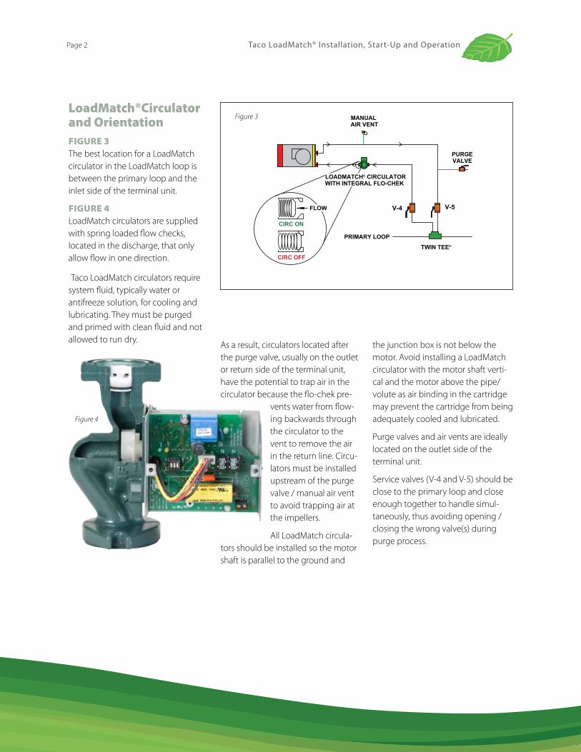
LoadMatch®Circulator and OrientationFIgure 3 The best location for a LoadMatch circulator in the LoadMatch loop is between the primary loop and the inlet side of the terminal unit.
FIgure 4 LoadMatch circulators are supplied with spring loaded flow checks, located in the discharge, that only allow flow in one direction.
Taco LoadMatch circulators require system fluid, typically water or antifreeze solution, for cooling and lubricating. They must be purged and primed with clean fluid and not allowed to run dry.
MANUAL AIR VENT
LOADMATCH® CIRCULATORWITH INTEGRAL FLO-CHEK
TWIN TEE®
V-4 V-5
PURGEVALVE
PRIMARY LOOP
CIRC ON
CIRC OFF
FLOW
Figure 3
Figure 4
As a result, circulators located after the purge valve, usually on the outlet or return side of the terminal unit, have the potential to trap air in the circulator because the flo-chek pre-
vents water from flow-ing backwards through the circulator to the vent to remove the air in the return line. Circu-lators must be installed upstream of the purge valve / manual air vent to avoid trapping air at the impellers.
All LoadMatch circula-tors should be installed so the motor shaft is parallel to the ground and
the junction box is not below the motor. Avoid installing a LoadMatch circulator with the motor shaft verti-cal and the motor above the pipe/volute as air binding in the cartridge may prevent the cartridge from being adequately cooled and lubricated.
Purge valves and air vents are ideally located on the outlet side of the terminal unit.
Service valves (V-4 and V-5) should be close to the primary loop and close enough together to handle simul-taneously, thus avoiding opening / closing the wrong valve(s) during purge process.
Taco LoadMatch® Installation, Start-Up and OperationPage 2
FILL
MANUALAIR VENT
PURGEVALVE
BOILER
TWIN TEE
SUCTIONDIFFUSER(S)
PRIMARYPUMP(S)
BALANCINGVALVE(S)
EXPANSIONTANK
AIR/DIRTSEPARATOR
AUTOMATICAIR VENT
V-1
V-2
V-3
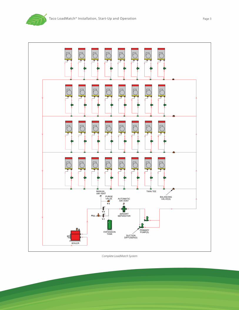
Complete LoadMatch System
Taco LoadMatch® Installation, Start-Up and Operation Page 3
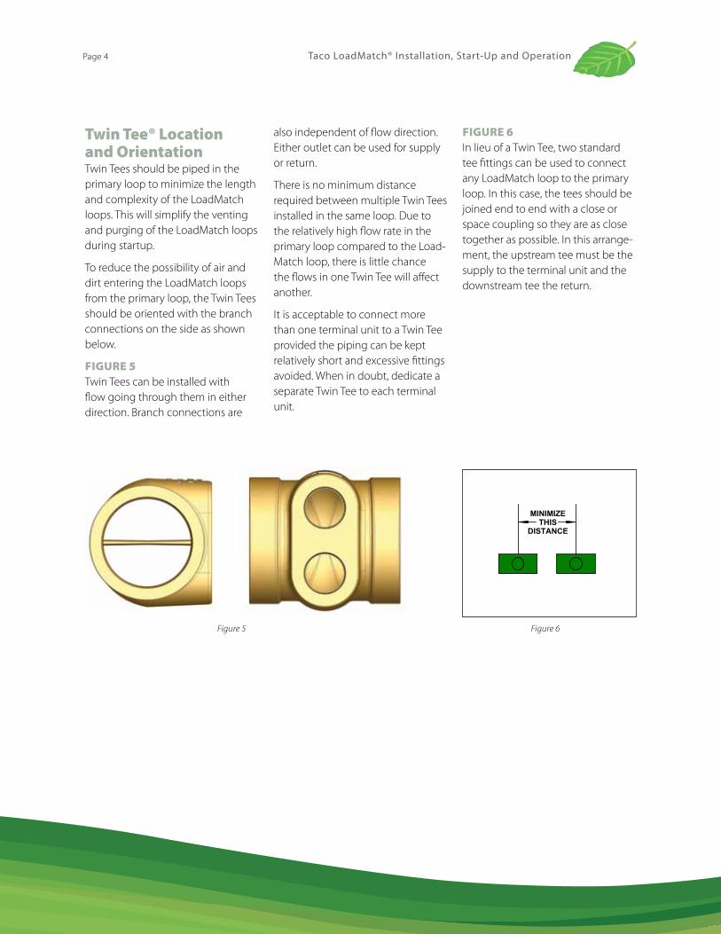
Twin Tee® Location and Orientation Twin Tees should be piped in the primary loop to minimize the length and complexity of the LoadMatch loops. This will simplify the venting and purging of the LoadMatch loops during startup.
To reduce the possibility of air and dirt entering the LoadMatch loops from the primary loop, the Twin Tees should be oriented with the branch connections on the side as shown below.
FIgure 5 Twin Tees can be installed with flow going through them in either direction. Branch connections are
also independent of flow direction. Either outlet can be used for supply or return.
There is no minimum distance required between multiple Twin Tees installed in the same loop. Due to the relatively high flow rate in the primary loop compared to the Load-Match loop, there is little chance the flows in one Twin Tee will affect another.
It is acceptable to connect more than one terminal unit to a Twin Tee provided the piping can be kept relatively short and excessive fittings avoided. When in doubt, dedicate a separate Twin Tee to each terminal unit.
FIgure 6 In lieu of a Twin Tee, two standard tee fittings can be used to connect any LoadMatch loop to the primary loop. In this case, the tees should be joined end to end with a close or space coupling so they are as close together as possible. In this arrange-ment, the upstream tee must be the supply to the terminal unit and the downstream tee the return.
Figure 5
MINIMIZETHIS
DISTANCE
Figure 6
Taco LoadMatch® Installation, Start-Up and OperationPage 4
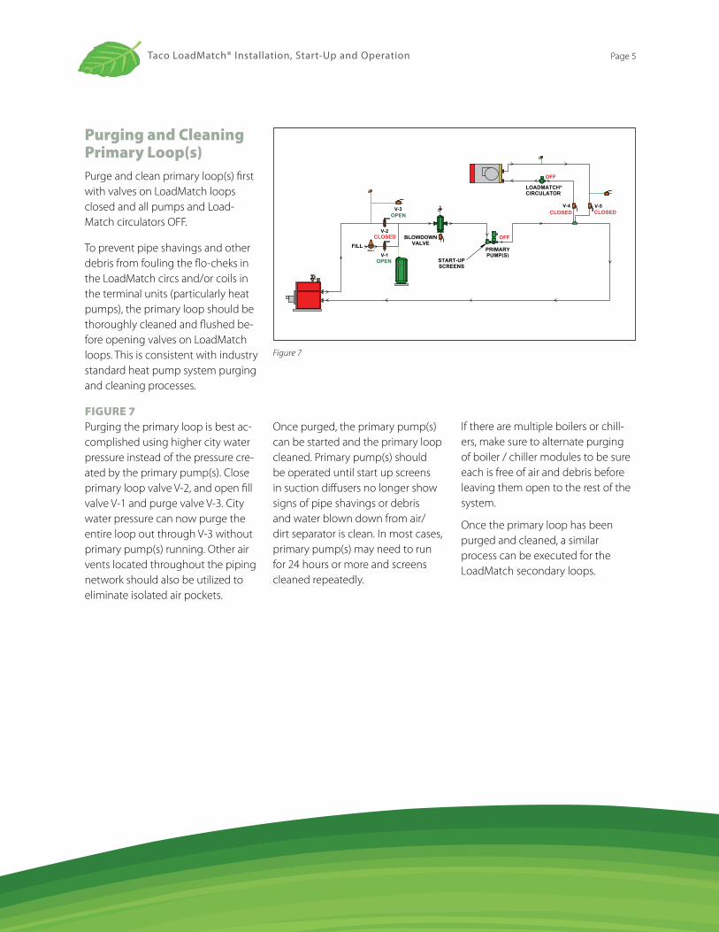
Purging and Cleaning Primary Loop(s)Purge and clean primary loop(s) first with valves on LoadMatch loops closed and all pumps and Load-Match circulators OFF.
To prevent pipe shavings and other debris from fouling the flo-cheks in the LoadMatch circs and/or coils in the terminal units (particularly heat pumps), the primary loop should be thoroughly cleaned and flushed be-fore opening valves on LoadMatch loops. This is consistent with industry standard heat pump system purging and cleaning processes.
FIgure 7 Purging the primary loop is best ac-complished using higher city water pressure instead of the pressure cre-ated by the primary pump(s). Close primary loop valve V-2, and open fill valve V-1 and purge valve V-3. City water pressure can now purge the entire loop out through V-3 without primary pump(s) running. Other air vents located throughout the piping network should also be utilized to eliminate isolated air pockets.
Once purged, the primary pump(s) can be started and the primary loop cleaned. Primary pump(s) should be operated until start up screens in suction diffusers no longer show signs of pipe shavings or debris and water blown down from air/dirt separator is clean. In most cases, primary pump(s) may need to run for 24 hours or more and screens cleaned repeatedly.
If there are multiple boilers or chill-ers, make sure to alternate purging of boiler / chiller modules to be sure each is free of air and debris before leaving them open to the rest of the system.
Once the primary loop has been purged and cleaned, a similar process can be executed for the LoadMatch secondary loops.
PRV-1FILL
V-1
V-2
V-3V-4 V-5
OPEN
OPEN
CLOSED
CLOSED CLOSED
OFF
OFF
PRIMARYPUMP(S)
LOADMATCH®
CIRCULATOR
BLOWDOWNVALVE
START-UPSCREENS
Figure 7
Taco LoadMatch® Installation, Start-Up and Operation Page 5
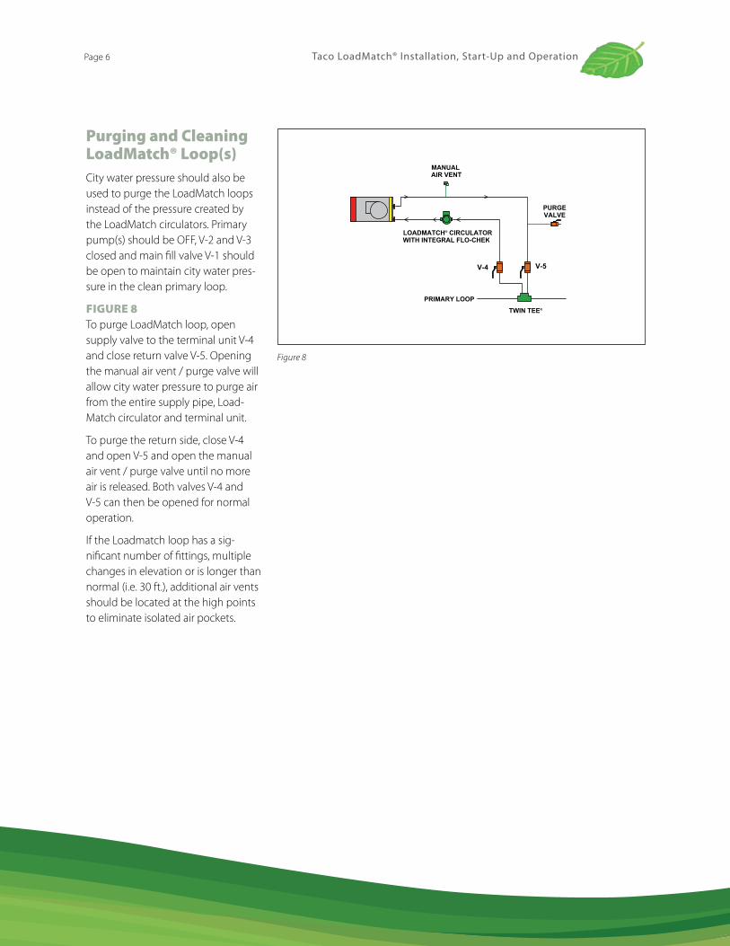
Purging and Cleaning LoadMatch® Loop(s)City water pressure should also be used to purge the LoadMatch loops instead of the pressure created by the LoadMatch circulators. Primary pump(s) should be OFF, V-2 and V-3 closed and main fill valve V-1 should be open to maintain city water pres-sure in the clean primary loop.
FIgure 8 To purge LoadMatch loop, open supply valve to the terminal unit V-4 and close return valve V-5. Opening the manual air vent / purge valve will allow city water pressure to purge air from the entire supply pipe, Load-Match circulator and terminal unit.
To purge the return side, close V-4 and open V-5 and open the manual air vent / purge valve until no more air is released. Both valves V-4 and V-5 can then be opened for normal operation.
If the Loadmatch loop has a sig-nificant number of fittings, multiple changes in elevation or is longer than normal (i.e. 30 ft.), additional air vents should be located at the high points to eliminate isolated air pockets.
MANUAL AIR VENT
LOADMATCH® CIRCULATORWITH INTEGRAL FLO-CHEK
TWIN TEE®
V-4 V-5
PURGEVALVE
PRIMARY LOOP
Figure 8
Taco LoadMatch® Installation, Start-Up and OperationPage 6
www.taco-hvac.com
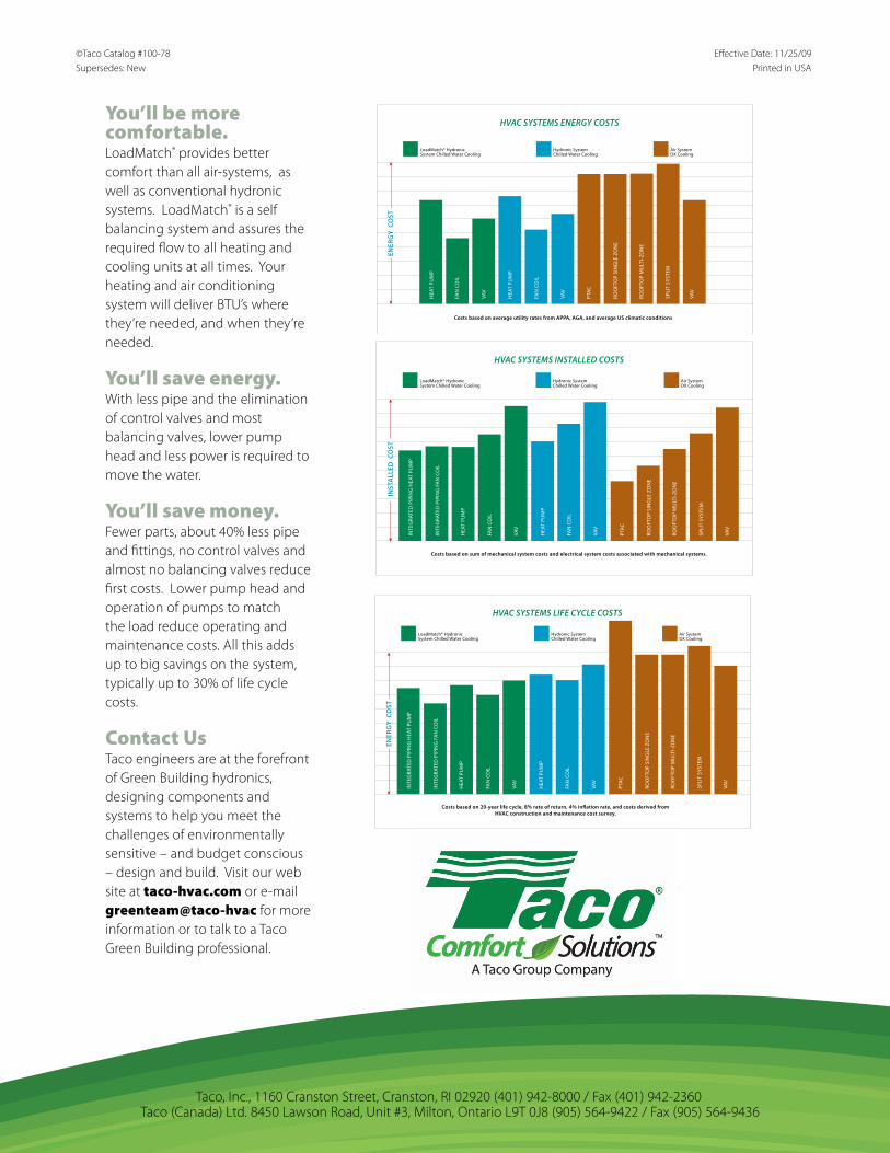
You’ll be more comfortable.LoadMatch® provides better comfort than all air-systems, as well as conventional hydronic systems. LoadMatch® is a self balancing system and assures the required flow to all heating and cooling units at all times. Your heating and air conditioning system will deliver BTU’s where they’re needed, and when they’re needed.
You’ll save energy. With less pipe and the elimination of control valves and most balancing valves, lower pump head and less power is required to move the water.
You’ll save money.Fewer parts, about 40% less pipe and fittings, no control valves and almost no balancing valves reduce first costs. Lower pump head and operation of pumps to match the load reduce operating and maintenance costs. All this adds up to big savings on the system, typically up to 30% of life cycle costs.
Contact usTaco engineers are at the forefront of Green Building hydronics, designing components and systems to help you meet the challenges of environmentally sensitive – and budget conscious – design and build. Visit our web site at taco-hvac.com or e-mail greenteam@taco-hvac for more information or to talk to a Taco Green Building professional.
©Taco Catalog #100-78 Effective Date: 11/25/09Supersedes: New Printed in USA
Taco, Inc., 1160 Cranston Street, Cranston, RI 02920 (401) 942-8000 / Fax (401) 942-2360 Taco (Canada) Ltd. 8450 Lawson Road, Unit #3, Milton, Ontario L9T 0J8 (905) 564-9422 / Fax (905) 564-9436