Embed Size (px)
Citation preview

OP
ER
AT
OR
'S M
AN
UA
LREAR BLADE &LANDSCAPE RAKEM
AN
1047
Rev
. 12
/20
/20
18
RBS54, RBS60, RBS72LRS52, LRS60, LRS72
RBS60P, RBS72P, RBS84PLRS72P, LRS84P, LRS96P

2 Introduction Gen’l (Rev. 2/25/2016)
TO THE DEALER:
Assembly and proper installation of this product is the responsibility of the Woods® dealer. Read manual instructionsand safety rules. Make sure all items on the Dealer’s Pre-Delivery and Delivery Check Lists in the Operator’s Manualare completed before releasing equipment to the owner.
The dealer must complete the online Product Registration form at the Woods Dealer Website which certifies thatall Dealer Check List items have been completed. Dealers can register all Woods product atdealer.WoodsEquipment.com under Product Registration.
Failure to register the product does not diminish customer’s warranty rights.
TO THE OWNER:
Read this manual before operating your Woods equipment. The information presented will prepare you to do a better andsafer job. Keep this manual handy for ready reference. Require all operators to read this manual carefully and becomeacquainted with all adjustment and operating procedures before attempting to operate. Replacement manuals can beobtained from your dealer. To locate your nearest dealer, check the Dealer Locator at www.WoodsEquipment.com, or inthe United States and Canada call 1-800-319-6637.
The equipment you have purchased has been carefully engineered and manufactured to provide dependable andsatisfactory use. Like all mechanical products, it will require cleaning and upkeep. Lubricate the unit as specified.Observe all safety information in this manual and safety decals on the equipment.
For service, your authorized Woods dealer has trained mechanics, genuine Woods service parts, and the necessarytools and equipment to handle all your needs.
Use only genuine Woods service parts. Substitute parts will void the warranty and may not meet standards required forsafe and satisfactory operation. Record the model number and serial number of your equipment in the spacesprovided:
Model: _______________________________ Date of Purchase: _____________________
Serial Number: (see Safety Decal section for location) ____________________________________
Provide this information to your dealer to obtain correct repair parts.
Throughout this manual, the term NOTICE is used to indicate that failure to observe can cause damage to equipment.The terms CAUTION, WARNING, and DANGER are used in conjunction with the Safety-Alert Symbol (a triangle withan exclamation mark) to indicate the degree of hazard for items of personal safety.

Introduction 3MAN1047 (Rev. 4/15/2014)
TABLE OF CONTENTS
INTRODUCTION . . . . . . . . . . . . . . . . . . . . . . . . . . . . INSIDE FRONT COVER
SPECIFICATIONS. . . . . . . . . . . . . . . . . . . . . . . . . . . . . . . . . . . . . . . . . . . . . 4
GENERAL INFORMATION . . . . . . . . . . . . . . . . . . . . . . . . . . . . . . . . . . . . . . 4
SAFETY RULES . . . . . . . . . . . . . . . . . . . . . . . . . . . . . . . . . . . . . . . . . . . . . . 5
SAFETY DECALS . . . . . . . . . . . . . . . . . . . . . . . . . . . . . . . . . . . . . . . . . . . . . 7
OPERATION . . . . . . . . . . . . . . . . . . . . . . . . . . . . . . . . . . . . . . . . . . . . . . . . . 9
MAINTENANCE . . . . . . . . . . . . . . . . . . . . . . . . . . . . . . . . . . . . . . . . . . . . . 14
ASSEMBLY . . . . . . . . . . . . . . . . . . . . . . . . . . . . . . . . . . . . . . . . . . . . . . . . 16
DEALER CHECK LISTS . . . . . . . . . . . . . . . . . . . . . . . . . . . . . . . . . . . . . . . 22
PARTS. . . . . . . . . . . . . . . . . . . . . . . . . . . . . . . . . . . . . . . . . . . . . . . . . . . . . 23
BOLT TORQUE CHART . . . . . . . . . . . . . . . . . . . . . . . . . . . . . . . . . . . . . . . 32
BOLT SIZE CHART & ABBREVIATIONS . . . . . . . . . . . . . . . . . . . . . . . . . . 33
PRODUCT WARRANTY . . . . . . . . . . . . . . . . . . . . . . . . . . . . . . . . . . . . . . . 34
REPLACEMENT PARTS WARRANTY . . . . . . . . . . . . INSIDE BACK COVER
Si no lee Ingles, pida ayuda a alguien que si lo lee para que le
traduzca las medidas de seguridad.
LEA EL INSTRUCTIVO!!
4 Introduction MAN1047 (Rev. 4/15/2014)
SPECIFICATIONS
GENERAL INFORMATIONThe purpose of this manual is to assist you in operatingand maintaining your equipment. Read it carefully. Itfurnishes information and instructions that will help youachieve years of dependable performance.
These instructions have been compiled from extensivefield experience and engineering data. Some informa-tion may be general in nature, due to unknown andvarying operating conditions. However, through experi-ence and these instructions, you should be able todevelop procedures suitable to your particular situa-tion.
The illustrations and data used in this manual were cur-rent at the time of printing. However, due to possibleinline production changes, your machine may varyslightly in detail. We reserve the right to redesign andchange the machines as may be necessary withoutnotification.
Throughout this manual, references are made to rightand left directions. These are determined by standingbehind the tractor facing the direction of forward travel.
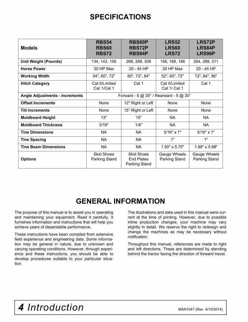
ModelsRBS54 RBS60 RBS72
RBS60P RBS72P RBS84P
LRS52 LRS60 LRS72
LRS72PLRS84P LRS96P
Unit Weight (Pounds) 134, 142, 156 268, 288, 308 156, 168, 186 264, 288, 311
Horse Power 30 HP Max 20 - 45 HP 30 HP Max 20 - 45 HP
Working Width 54", 60", 72" 60", 72", 84" 52", 60", 72" 72", 84", 96"
Hitch Category Cat 0/Limited Cat 1/Cat 1
Cat 1 Cat 0/Limited Cat 1/ Cat 1
Cat 1
Angle Adjustments - Increments Forward - 5 @ 30° / Rearward - 5 @ 30°
Offset Increments None 12" Right or Left None None
Tilt Increments None 15° Right or Left None None
Moldboard Height 13" 15" NA NA
Moldboard Thickness 3/16" 1/4" NA NA
Tine Dimensions NA NA 5/16" x 1" 5/16" x 1"
Tine Spacing NA NA 1" 1"
Tine Beam Dimensions NA NA 1.50" x 5.75" 1.88" x 5.88"
OptionsSkid Shoes
Parking StandSkid ShoesEnd Plates
Parking Stand
Gauge WheelsParking Stand
Gauge WheelsParking Stand

Safety 5RB S/LRS SR (Re v . 4/9/2014)
TRAINING
Safety instructions are important! Read allattachment and power unit manuals; follow allsafety rules and safety decal information. (Replace-ment manuals and safety decals are available fromyour dealer. To locate your nearest dealer, checkthe Dealer Locator at www.WoodsEquipment.com,or in the United States and Canada call 1-800-319-6637.) Failure to follow instructions or safety rulescan result in serious injury or death.
If you do not understand any part of this manualand need assistance, see your dealer.
Know your controls and how to shut downquickly in an emergency.
Operators must be instructed in and be capableof the safe operation of the equipment, its attach-ments, and all controls. Do not allow anyone tooperate this equipment without proper instructions.
Never allow children or untrained persons tooperate equipment.
PREPARATION
Check that all hardware is properly installed.Always tighten to torque chart specificationsunless instructed otherwise in this manual.
Always wear relatively tight and belted clothingto avoid entanglement in moving parts. Wearsturdy, rough-soled work shoes and protectiveequipment for eyes, hair, hands, hearing, and head;and respirator or filter mask where appropriate.
Make sure attachment is properly secured,adjusted, and in good operating condition.
Power unit must be equipped with ROPS orROPS cab and seat belt. Keep seat belt securelyfastened. Falling off power unit can result in death
from being run over or crushed. Keep foldableROPS systems in “locked up” position at all times.
Make sure all safety decals are installed.Replace if damaged. (See Safety Decals section forlocation.)
A minimum 20% of tractor and equipmentweight must be on the tractor front wheels whenattachments are in transport position. Without thisweight, front tractor wheels could raise up result-ing in loss of steering. The weight may be attainedwith front wheel weights, ballast in tires, front trac-tor weights or front loader. Weigh the tractor andequipment. Do not estimate.
OPERATION
Consult local utilities before working. Knowlocation of all underground cables, pipelines, over-head wires, and other hazards in working area andavoid contact.
Keep bystanders away from equipment.
Do not operate or transport equipment whileunder the influence of alcohol or drugs.
Operate only in daylight or good artificial light.
Keep hands, feet, hair, and clothing away fromequipment while engine is running. Stay clear of allmoving parts.
Always comply with all state and local lightingand marking requirements.
Never allow riders on power unit or attachment.
Power unit must be equipped with ROPS orROPS cab and seat belt. Keep seat belt securelyfastened. Falling off power unit can result in deathfrom being run over or crushed. Keep foldableROPS systems in “locked up” position at all times.
Always sit in power unit seat when operatingcontrols or starting engine. Securely fasten seatbelt, place transmission in neutral, engage brake,and ensure all other controls are disengagedbefore starting power unit engine.
Look down and to the rear and make sure areais clear before operating in reverse.
Do not operate or transport on steep slopes.
(Safety Rules continued on next page)
Safety is a primary concern in the design andmanufacture of our products. Unfortunately, ourefforts to provide safe equipment can be wipedout by an operator’s single careless act.
In addition to the design and configuration ofequipment, hazard control and accident preven-tion are dependent upon the awareness, concern,judgement, and proper training of personnelinvolved in the operation, transport, maintenanceand storage of equipment.
It has been said “The best safety device is aninformed, careful operator.” We ask you to be thatkind of operator.
SAFETY RULESATTENTION! BECOME ALERT! YOUR SAFETY IS INVOLVED!

6 Safety RB S/LRS SR (Re v . 4/9/2014)
(Safety Rules continued from previous page) Do not stop, start, or change directions sud-denly on slopes.
Use extreme care and reduce ground speed onslopes and rough terrain.
Watch for hidden hazards on the terrain duringoperation.
Stop power unit and equipment immediatelyupon striking an obstruction. Turn off engine,remove key, inspect, and repair any damage beforeresuming operation.
Before changing positions of manual swing, tilt,or angle positions:
• Park tractor on level ground, apply parkingbrake, level implement boom, shut off tractor,and remove key.• Make manual changes slowly and carefullyto prevent hazardous movement of mecha-nisms.• Never stand in positions where you couldbecome entrapped during adjustment changesor if the 3-point hitch suddenly lowers.
Always secure lock pins with safety pins to pre-vent lock pins from bumping out of the positioningholes. Failure to do so may result in accidents and/or damage to blade.
Before dismounting power unit or performingany service or maintenance, follow these steps:disengage power to equipment, lower the 3-pointhitch and all raised components to the ground,operate valve levers to release any hydraulic pres-sure, set parking brake, stop engine, remove key,and unfasten seat belt.
NEVER GO UNDERNEATH EQUIPMENT. Neverplace any part of the body underneath equipmentor between moveable parts even when the enginehas been turned off. Hydraulic system leak down,hydraulic system failures, mechanical failures, ormovement of control levers can cause equipmentto drop or rotate unexpectedly and cause severeinjury or death.
• Service work does not require going under-neath.• Read Operator's Manual for service instruc-tions or have service performed by a qualifieddealer.
MAINTENANCE
Before dismounting power unit or performingany service or maintenance, follow these steps:
disengage power to equipment, lower the 3-pointhitch and all raised components to the ground,operate valve levers to release any hydraulic pres-sure, set parking brake, stop engine, remove key,and unfasten seat belt.
NEVER GO UNDERNEATH EQUIPMENT. Neverplace any part of the body underneath equipmentor between moveable parts even when the enginehas been turned off. Hydraulic system leak down,hydraulic system failures, mechanical failures, ormovement of control levers can cause equipmentto drop or rotate unexpectedly and cause severeinjury or death.
• Service work does not require going under-neath.• Read Operator's Manual for service instruc-tions or have service performed by a qualifieddealer.
Always wear relatively tight and belted clothingto avoid entanglement in moving parts. Wearsturdy, rough-soled work shoes and protectiveequipment for eyes, hair, hands, hearing, and head;and respirator or filter mask where appropriate.
Make sure attachment is properly secured,adjusted, and in good operating condition.
Keep all persons away from operator controlarea while performing adjustments, service, ormaintenance.
Tighten all bolts, nuts and screws to torquechart specifications. Check that all cotter pins areinstalled securely to ensure equipment is in a safecondition before putting unit into service.
Make sure all safety decals are installed.Replace if damaged. (See Safety Decals section forlocation.)
STORAGE
Block equipment securely for storage.
Keep children and bystanders away from stor-age area.
Follow manual instructions for storage.
SAFETY RULESATTENTION! BECOME ALERT! YOUR SAFETY IS INVOLVED!

Safety 7MAN1047 (Rev. 4/15/2014)
SAFETY & INSTRUCTIONAL DECALSATTENTION! BECOME ALERT! YOUR SAFETY IS
INVOLVED!

8 Safety MAN1047 (Rev. 4/15/2014)
SAFETY & INSTRUCTIONAL DECALSATTENTION! BECOME ALERT! YOUR SAFETY IS INVOLVED!
Replace Immediately If Damaged!
2 - 1004299Serial Number Plate
MODEL NO. SERIAL NO.
Woods Equipment CompanyOregon, Illinois, U.S.A.
BE CAREFUL!
Use a clean, damp cloth to clean safety decals.
Avoid spraying too close to decals when using a pressure washer; high-pressurewater can enter through very small scratches or under edges of decals causingthem to peel or come off.
Replacement safety decals can be ordered free from your Woods dealer. To locateyour nearest dealer, check the Dealer Locator at www.WoodsEquipment.com, or inthe United States and Canada call 1-800-319-6637.
1 - 1002941
3 - 1004250
Operation 9MAN1047 (Rev. 4/15/2014)
OPERATIONThe operator is responsible for the safe operation ofthis equipment. Operators must be instructed in and becapable of the safe operation of the equipment, itsattachments and all controls. Do not allow anyone tooperate this equipment without proper instructions.
This equipment is designed for a wide range of applica-tions. The blade may be used for scraping, leveling,grading and backfilling. The rake may be used for loos-ening, leveling and clearing soil of debris.
The blade or rake may be angled to windrow debris tothe side for removal.
Never allow children or untrained persons tooperate equipment.
Keep bystanders away from equipment.
Never allow riders on power unit or attachment.
A minimum 20% of tractor and equipmentweight must be on the tractor front wheels whenattachments are in transport position. Without thisweight, tractor could tip over, causing personalinjury or death. The weight may be attained with aloader, front wheel weights, ballast in tires or fronttractor weights. Weigh the tractor and equipment.Do not estimate.
Always wear relatively tight and belted clothingto avoid entanglement in moving parts. Wearsturdy, rough-soled work shoes and protectiveequipment for eyes, hair, hands, hearing, and head;and respirator or filter mask where appropriate.
CONNECT REAR BLADE OR RAKE TO TRACTOR
1. This rake or blade should be mounted on tractorswith a maximum drawbar rating of 30 engine hp,not to exceed 2400 lbs.
2. Adjust or remove tractor drawbar to eliminateinterference with blade or rake.
Category 1
1. Place tractor 3-point lower lift arms over outer hitchpins.
2. Secure with klik pin (not provided) as shown inFigure 1.
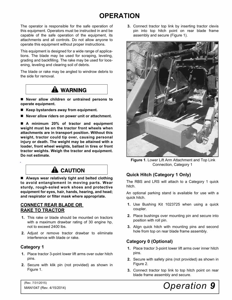
3. Connect tractor top link by inserting tractor clevispin into top hitch point on rear blade frameassembly and secure (Figure 1).
Figure 1. Lower Lift Arm Attachment and Top Link Connection, Category 1
Quick Hitch (Category 1 Only)
The RBS and LRS will attach to a Category 1 quickhitch.
An optional parking stand is available for use with aquick hitch.
1. Use Bushing Kit 1023725 when using a quickcoupler.
2. Place bushings over mounting pin and secure intoposition with roll pin.
3. Align quick hitch with mounting pins and secondhole from top on rear blade frame assembly.
Category 0 (Optional)
1. Place tractor 3-point lower lift arms over inner hitchpins.
2. Secure with safety pins (not provided) as shown inFigure 2.
3. Connect tractor top link to top hitch point on rearblade frame assembly and secure.
�������
CAUTION
(Rev. 7/31/2015)
10 Operation MAN1047 (Rev. 4/15/2014)
Figure 2. Lower Lift Arm Attachment, Category 0
Category 0 / 1 Hitch Pin Kit (Optional)
1. Remove existing hitch pins.
2. Place hitch pin (1) through rear blade assembly.
3. Secure with flat washer (2), lock washer (3) andhex nut (4).
4. Repeat for opposite side. See Figure 3.
Figure 3. Hitch Pin Kit (Optional)
OPERATING TECHNIQUES
Level the A-frame and boom with 3-point connectinglinks and top link. Adjusting the top link length willchange the fore and aft pitch of the tool.
Lengthening the top link will cause the tool to contactthe ground with a sharper pitch and feed itself into theground more readily.
When using the rake tool, you may need to adjust thetail wheels after adjusting pitch to maintain the desiredworking depth.
Position 3-point lift arm sway blocks or tighten swaychains to eliminate side sway. Install side braces if nec-essary.
Reversing (Blade or Rake)For most tractors, the blade or rake may be rotated 360degrees without unhooking from the tractor. To rotatewithout unhooking, pull hitch pin assembly.
Rotate to desired position; replace hitch pin assembly.
Angling (Blade or Rake)Remove hitch pin assembly.
The blade or rake may be set 15 degrees or 30degrees to the left or right for forward grading.
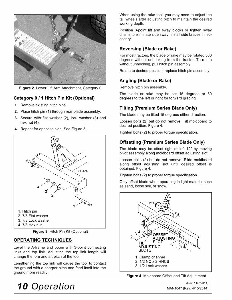
Tilting (Premium Series Blade Only)The blade may be tilted 15 degrees either direction.
Loosen bolts (2) but do not remove. Tilt moldboard todesired position. Figure 4.
Tighten bolts (2) to proper torque specification.
Offsetting (Premium Series Blade Only)The blade may be offset right or left 12" by movingpivot assembly along moldboard offset adjusting slot
Loosen bolts (2) but do not remove. Slide moldboardalong offset adjusting slot until desired offset isobtained. Figure 4.
Tighten bolts (2) to proper torque specification..
Only offset blade when operating in light material suchas sand, loose soil, or snow.
Figure 4. Moldboard Offset and Tilt Adjustment
1. Hitch pin2. 7/8 Flat washer3. 7/8 Lock washer4. 7/8 Hex nut
1. Clamp channel2. 1/2 NC x 2 HHCS3. 1/2 Lock washer
(Rev. 11/7/2014)

Operation 11MAN1047 (Rev. 4/15/2014)
Backfilling
Reverse blade for backfilling ditches or trenches (seeReversing).
The rake may also be used in light backfilling applica-tions.
Cutting Ditches (Premium Series Blade Only)
Loosen bolts (2) but do not remove. Tilt moldboard leftor right until desired blade angle is obtained.
Tighten bolts (2) to proper torque specification.
Angle blade to bring lower end forward. Bring lowerpoint near the center line of the rear wheel track using3-point hitch height adjustment. Figure 4.
Parking Stand Placement (Optional)
Assembly
1. Assemble parking stand holder (1) toward center offrame assembly using 3/8 hex head cap screw (3),3/8 flat washers (4) and secure with 3/8 hex nut (5).Do not allow parking stand holder to cover anyportion of safety decal. Figure 5.
Operating Position
1. Slide parking stand (2) into holder (1) and alignlowest hole in parking stand with hole in parkingstand holder.
2. Secure parking stand into position using lock pin(6).
Storage Position
1. Raise tractor 3-point arms.
2. Remove parking stand (2) from operating position.
3. Align hole in parking stand holder with appropriatehole in parking stand according to your particularblade or rake and secure into position with lock pin(6).
Figure 5. Parking Stand Assembly (Optional)
1. Parking stand holder
2. Parking stand
3. 3/8 NC x 3-3/4 HHCS (Standard)
3. 3/8 NC x 4-1/4 HHCS (Premium)
4. 3/8 Flat washer
5. 3/8 NC hex nut
6. 3/8 x 2-1/4 Lynch pin

12 Operation MAN1047 (Rev. 4/15/2014)
TAIL WHEEL ADJUSTMENT (OPTIONAL) (STANDARD LANDSCAPE RAKE ONLY)
Figure 6. Tail Wheel Adjustment (Standard)
IMPORTANT■ When optional tail wheels are installed behindrake, you must raise rake and tail wheels off ofground before operating in reverse.
1. Raise rake until wheels clear the ground.
2. Remove klik pin (5) from yoke shaft while holdingwheel. Remove flat washer (4).
3. Add or remove 1/2” thick spacers (3) above orbelow tail wheel arm (2).
4. Placing spacers below tail wheel arm raises therake height.
5. When height is established, secure assembly byinstalling flat washer (4) and klik pin (5).
6. Adjust the pitch of the rake to maintain the desiredworking depth.
7. Position 3-point lift arm sway blocks or tightensway chains to eliminate side sway. Install sidebraces if necessary.
NOTE: Use a good multi-purpose grease to lubri-cate pivot tube and tail wheel every 8 hours ofoperation.
TAIL WHEEL ADJUSTMENT (OPTIONAL) (PREMIUM LANDSCAPE RAKE ONLY)
Figure 7. Tail Wheel Adjustment (Premium)
IMPORTANT■ When optional tail wheels are installed behindrake, you must raise rake and tail wheels off ofground before operating in reverse.
1. Raise rake until wheels clear the ground.
2. Remove klik pin (6) from yoke shaft while holdingwheel. Remove flat washer (5).
3. Add or remove any combination of 1/2” thickspacers (3 ) and 1” thick spacers (4) above orbelow tail wheel arm (2).
4. Placing any spacer below tail wheel arm raises therake height.
5. When height is established, secure assembly byinstalling flat washer (5) and klik pin (5).
6. Adjust the pitch of the rake to maintain the desiredworking depth.
7. Position 3-point lift arm sway blocks or tightensway chains to eliminate side sway. Install sidebraces if necessary.
NOTE: Use a good multi-purpose grease to lubri-cate pivot tube and tail wheel every 8 hours ofoperation.
1. Yoke & wheel assembly
2. Tail wheel arm
3. 1/2” Thick spacer
4. 1-1/16 x 1-9/16 x 1/8 Flat washer
5. 1/4 x 1-3/4 Klik pin
1. Yoke & wheel assembly
2. Tail wheel arm
3. 1/2” Thick spacer
4. 1” Thick spacer
5. 1-1/16 x 1-9/16 x 1/8 Flat washer
6. 1/4 x 1-3/4 klik pin

Operation 13MAN1047 (Rev. 4/15/2014)
PRE-OPERATION CHECK LIST
(Owner’s Responsibility Before Each Use)
___ Review and follow all safety rules and safetydecal instructions on pages 5 through 8.
___ Check that all safety decals are installed and ingood condition. Replace if damaged.
___ Check that all hardware is properly installed andsecured.
___ Check that equipment is properly and securelyattached to tractor.
___ Do not allow riders.
___ Make sure tractor ROPS or ROPS cab and seatbelt are in good condition. Keep seat beltsecurely fastened during operation.
___ Check that blade cutting edge is in good condi-tion.
___ Consult local utilities before digging. Know loca-tion of and avoid contacting all undergroundcables, pipelines, overhead wires and other haz-ards in digging area.

14 Maintenance MAN1047 (Rev. 4/15/2014)
MAINTENANCEThe information in this section is written for operatorswho possess basic mechanical skills. If you need help,your dealer has trained service technicians available.For your protection, read and follow all safety informa-tion in this manual.
Before dismounting power unit or performingany service or maintenance, follow these steps:disengage power to equipment, lower the 3-pointhitch and all raised components to the ground,operate valve levers to release any hydraulic pres-sure, set parking brake, stop engine, remove key,and unfasten seat belt.
NEVER GO UNDERNEATH EQUIPMENT. Neverplace any part of the body underneath equipmentor between moveable parts even when the enginehas been turned off. Hydraulic system leak down,hydraulic system failures, mechanical failures, ormovement of control levers can cause equipmentto drop or rotate unexpectedly and cause severeinjury or death.
• Service work does not require going under-neath.• Read Operator's Manual for service instruc-tions or have service performed by a qualifieddealer.
Keep all persons away from operator controlarea while performing adjustments, service, ormaintenance.
Always wear relatively tight and belted clothingto avoid entanglement in moving parts. Wearsturdy, rough-soled work shoes and protectiveequipment for eyes, hair, hands, hearing, and head;and respirator or filter mask where appropriate.
REPLACING BLADE CUTTING EDGE
Remove Cutting Edge
1. Remove plow bolts (3), and hex lock nuts (4).
2. Remove cutting edge (2) from moldboard (1) andreplace with new cutting edge. Re-install hardwarepreviously removed.
Reverse Cutting Edge
1. Remove plow bolts (3), and hex lock nuts (4).
2. Remove cutting edge (2) from moldboard andreverse cutting edge with sharp edge down. Re-install hardware previously removed.
Figure 8. Cutting Edge Replacement
�������
CAUTION
1. Moldboard2. Cutting edge3. 5/8 NC Plow bolt4. 5/8 NC Hex lock nut

Maintenance 15MAN1047 (Rev. 4/15/2014)
RAKE TINE REPLACEMENT
NOTE: Tines should be replaced when they cannot bereformed to their original configuration.
NOTE: Tine clamp channel (3) does not need to becompletely removed to remove tines.
1. Loosen carriage bolts (4) and flange lock nuts (5)holding tine beam (2) and tine clamp channel (3)together. It is not necessary to completely removehardware. Remove old tine.
2. Inset new tine, hole end first, into slot in rear of tinebeam (2) and assemble hole in tine onto nub infront of tine channel. Tighten carriage bolts (4) andflange lock nuts (5).
Figure 9. Rake Tine Replacement
CLEANING
After Each Use
● Remove large debris such as clumps of dirt, grass,crop residue, etc. from machine.
● Inspect machine and replace worn or damagedparts.
● Replace any safety decals that are missing or notreadable.
Periodically or Before Extended Storage
● Clean large debris such as clumps of dirt, grass,crop residue, etc. from machine.
● Remove the remainder using a low-pressure waterspray.
1. Be careful when spraying near scratched or tornsafety decals or near edges of decals as waterspray can peel decal off surface.
2. Be careful when spraying near chipped orscratched paint as water spray can lift paint.
3. If a pressure washer is used, follow the adviceof the pressure washer manufacturer.
● Inspect machine and replace worn or damagedparts.
● Sand down scratches and the edges of areas ofmissing paint and coat with Woods spray paint ofmatching color (purchase from your Woodsdealer).
● Replace any safety decals that are missing or notreadable (supplied free by your Woods dealer).See Safety Decals section for location drawing.
1. Rake tine2. Rake tine beam3. Tine clamp channel4. Carriage bolt5. Flange hex lock nut

16 Assembly MAN1047 (Rev. 4/15/2014)
ASSEMBLY INSTRUCTIONS
DEALER SET-UP INSTRUCTIONS
Assembly of this Rear Blade/Landscape Rake is theresponsibility of the WOODS dealer. It should be deliv-ered to the owner completely assembled, lubricatedand adjusted for normal cutting conditions.
The Rear Blade/Landscape Rake is shipped partiallyassembled. Assembly will be easier if components arealigned and loosely assembled before tightening hard-ware. Recommended torque values for hardware arelocated on page 24.
Before dismounting power unit or performingany service or maintenance, follow these steps:disengage power to equipment, lower the 3-pointhitch and all raised components to the ground,operate valve levers to release any hydraulic pres-sure, set parking brake, stop engine, remove key,and unfasten seat belt.
NEVER GO UNDERNEATH EQUIPMENT. Neverplace any part of the body underneath equipmentor between moveable parts even when the enginehas been turned off. Hydraulic system leak-down,hydraulic system failures, mechanical failures, ormovement of control levers can cause equipmentto drop or rotate unexpectedly and cause severeinjury or death.
• Service work does not require going under-neath implement.• Read Operator's Manual for service instruc-tions or have service performed by a qualifieddealer.
Keep all persons away from operator controlarea while performing adjustments, service, ormaintenance.
Always wear relatively tight and belted clothingto avoid entanglement in moving parts. Wearsturdy, rough-soled work shoes and protectiveequipment for eyes, hair, hands, hearing, and head;and respirator or filter mask where appropriate.
Blade and Rake Assembly
Blade and Rake Assembly (Standard)
1. Assemble frame assembly onto threaded stud onmoldboard or tine beam assembly and secure withflat washer (12) and nylock nut (13).
2. Remove hitch channel (3) from frame assembly.Reassemble channel to frame with 1/2 NC x 3-1/2hex cap screw (7) and 1/2 NC flange lock nut (9).
3. Assemble top holes of hitch channel to middle holeof hitch links (4) using 3/4 NC x 3-1/2 hex capscrew (10) and 3/4 NC flange lock nut (11).Assemble sleeve (5) between hitch links.
4. Install 3/4 x 5 hitch pin (14) thru hole in frameassembly and into desired hole in pivot plate ofmoldboard or tine beam.
Figure 10. Standard Blade and Rake Assembly
�������
CAUTION
1. Moldboard assembly -OR-1. Tine beam assembly2. Frame assembly3. Hitch channel4. Hitch link5. 13/16 x 1-1/4 x 1-3/4 sleeve6. 1/2 NC x 3 Hex head cap screw7. 1/2 NC x 3-1/2 Hex head cap screw8. 1/2 Extra thick hardened flat washer9. 1/2 NC flange hex lock nut
10. 3/4 NC x 3-1/2 Hex head cap screw11. 3/4 NC flange hex lock nut12. 1-1/16 x 2 x 9/64 Flat washer13. 1" NC Nylock hex nut14. 3/4 x 5 Cotterless hitch pin

Assembly 17MAN1047 (Rev. 4/15/2014)
Blade Assembly (Premium)
1. Remove clamp channel (4) from pivot assembly(3). Insert clamp channel into main channel onback of moldboard (2). Reinstall 1/2 NC x 2 hexcap screw (5), 1/2 lock washer (6) and 1/2 x 1-1/2 x1/4 flat washer (7) to secure pivot to moldboard.
2. Support moldboard and pivot assembly in anupright position.
3. Place blade frame assembly (1) onto threaded studon pivot assembly and secure with nylock nut (15).
Install hitch pin (16) through hole in frame and intodesired hole in pivot assembly.
4. Assemble left and right mast plates (8 & 9) to frameassembly (1) using 1/2 NC x 3-1/2 hex cap screws(10) and 1/2 NC flange lock nuts (11).
5. Assemble 13/16 x 1-1/4 x 1-3/4 sleeve (12)between mast plates and secure with 3/4 NC x 3-1/2hex cap screw (13) and 3/4 NC flange lock nut(14). Torque all hardware.
Figure 11. Premium Blade Assembly
1. Frame assembly
2. Moldboard assembly
3. Pivot assembly
4. Clamp channel
5. 1/2 NC x 2 Hex head cap screw
6. 1/2 Lock washer
7. 1/2 x 1-1/2 x 1/4 Flat washer
8. Right mast plate
9. Left mast plate
10. 1/2 NC x 3-1/2 Hex head cap screw
11. 1/2 NC Flange hex lock nut
12. 13/16 x 1-1/4 x 1-3/4 Sleeve
13. 3/4 NC x 3-1/2 Hex head cap screw
14. 3/4 NC Flange hex lock nut
15. 1-1/4 NC Nylock hex nut
16. 3/4 x 5 Cotterless hitch pin
(Rev. 6/15/2017)

18 Assembly MAN1047 (Rev. 4/15/2014)
Figure 12. Premium Rake Assembly
Rake Assembly (Premium)
1. Assemble frame assembly (1) onto threaded studon tine beam assembly (2) and secure with nylocknut (10). Install hitch pin (11) thru hole in frame andinto desired hole in tine beam assembly.
2. Assemble left and right mast plates (3 & 4) to frameassembly (1) using 1/2 NC x 3-1/2 hex cap screws(6) and 1/2 NC flange lock nuts (7).
3. Assemble 13/16 x 1-1/4 x 1-3/4 sleeve (5) betweenmast plates and secure with 3/4 NC x 3-1/2 hexcap screw (8) and 3/4 NC flange lock nut (9).Torque all hardware.
Tail Wheel Installation (Optional)(Landscape Rake Only)
1. Remove landscape rake from tractor 3-point liftarms if attached.
2. Roll landscape rake over with tines pointingupward.
3. Place jack stands or suitable blocking device undertine beam to raise tine beam approximately 8 to 10inches.
4. Place tail wheel arm assembly (2) between lugs ontine beam and align holes.
5. Secure into position using three 1/2 NC x 1-1/2 hexcap screws (3) and 1/2 NC flange lock nuts (4).
Figure 13. Tail Wheel Installation
1. Frame assembly
2. Tine beam assembly
3. Right mast plate
4. Left mast plate
5. 13/16 x 1-1/4 x 1-3/4 Sleeve
6. 1/2 NC x 3-1/2 Hex head cap screw
7. 1/2 NC Flange hex lock nut
8. 3/4 NC x 3-1/2 Hex head cap screw
9. 3/4 NC Flange hex lock nut
10. 1-1/4 Nylock hex nut
11. 3/4 x 5 Cotterless hitch pin
1. Tine beam assembly
2. Tail wheel assembly
3. 1/2 NC x 1-1/2 Hex head cap screw
4. 1/2 NC Flange hex lock nut
(Rev. 6/15/2017)

Assembly 19MAN1047 (Rev. 4/15/2014)
Quick Hitch Bushing Kit (Optional)
Figure 14. Quick Hitch Bushing Kit
1. Place sleeve (1) over lower 3-point pin, secure withroll pin (2). Repeat for opposite side.
Parking Stand (Optional
Assembly
1. Assemble parking stand holder (1) toward center offrame assembly using 3/8 NC hex cap screw (3),3/8 flat washers (4) and secure with 3/8 NC hex nut(5). Do not allow parking stand holder to cover anyportion of safety decal. Figure 17.
Operating Position
1. Slide parking stand (2) into holder (1) and alignlowest hole in parking stand with hole ib parkingstand holder.
2. Secure parking stand into position using lock pin(6).
Storage Position
1. Raise tractor 3-point arms.
2. Remove parking stand from operating position.
3. Align hole in parking stand holder with appropriatehole in parking stand according to your particularblade or rake and secure into position with lock pin(6).
Figure 15. Parking Stand
1. .94 x 1.44 x 4.00 Sleeve
2. 7/16 x 1-3/8 Roll pin
1. Parking stand holder
2. Parking stand
3. 3/8 NC x 3-3/4 HHCS (Standard)
3. 3/8 NC x 4-1/4 HHCS (Premium)
4. 3/8 Flat washer
5. 3/8 NC hex nut
6. 3/8 x 2-1/4 Lynch pin
(Rev. 7/31/2015)

20 Assembly MAN1047 (Rev. 4/15/2014)
Category 0 / 1 Hitch Pin Kit (Optional)
1. Remove existing hitch pins.
2. Place hitch pin (1) through rear blade assembly.
3. Secure with flat washer (2), lock washer (3) andhex nut (4).
4. Repeat for opposite side. See Figure 18.
Figure 16. Hitch Pin Kit
End Plate Kit (RBS Premium Only) (Optional)
Figure 17. End Plate Installation
Assemble one end plate (2) to each end of blade usingtwo carriage bolts (3) and flange lock nuts (4) on eachend plate.
Skid Shoe Kit (Optional)
1. Remove plow bolts from each end of cutting edge.
2. Attach skid shoe (1) to rear of moldboard with 5/8NC x 2 plow bolt (2), 5/8 hardened flat washer (3)and 5/8 NC hex lock nut (4), supplied in kit.
3. Adjust skid shoe to desired height.
4. Repeat steps for opposite side of moldboard.
Figure 18. Basic Skid Shoe Installation
1. Hitch pin2. 7/8 Flat washer3. 7/8 Lock washer4. 7/8 Hex nut
1. Blade moldboard2. End plate3. 1/2 NC x 1-1/4 Carriage bolt4. 1/2 NC Flange hex lock nut
1. Skid shoe
2. 5/8 NC x 2 Plow bolt
3. 5/8 Hardened flat washer
4. 5/8 NC Hex lock nut
Assembly 21MAN1047 (Rev. 4/15/2014)
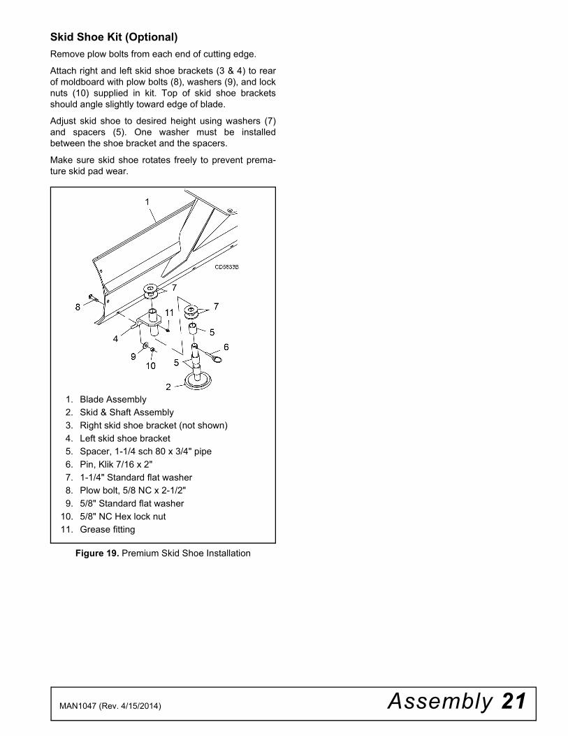
Skid Shoe Kit (Optional)
Remove plow bolts from each end of cutting edge.
Attach right and left skid shoe brackets (3 & 4) to rearof moldboard with plow bolts (8), washers (9), and locknuts (10) supplied in kit. Top of skid shoe bracketsshould angle slightly toward edge of blade.
Adjust skid shoe to desired height using washers (7)and spacers (5). One washer must be installedbetween the shoe bracket and the spacers.
Make sure skid shoe rotates freely to prevent prema-ture skid pad wear.
Figure 19. Premium Skid Shoe Installation
1. Blade Assembly
2. Skid & Shaft Assembly
3. Right skid shoe bracket (not shown)
4. Left skid shoe bracket
5. Spacer, 1-1/4 sch 80 x 3/4" pipe
6. Pin, Klik 7/16 x 2"
7. 1-1/4" Standard flat washer
8. Plow bolt, 5/8 NC x 2-1/2"
9. 5/8" Standard flat washer
10. 5/8" NC Hex lock nut
11. Grease fitting

22 Dealer Check Lists MAN1047 (Rev. 4/15/2014)
DEALER CHECK LISTS
PRE-DELIVERY CHECK LIST
Inspect the equipment thoroughly after assembly toensure it is set up properly before delivering it to thecustomer.
The following check lists are a reminder of points toinspect. Check off each item as it is found satisfactoryor after proper adjustment is made.
___ Check that all safety decals are installed and ingood condition. Replace if damaged.
___ Properly attach implement to tractor and make allnecessary adjustments.
___ Check parking stand for proper operation.
___ Check all bolts to be sure they are properlytorqued.
___ Check that all cotter pins and safety pins areproperly installed. Replace if damaged.
DELIVERY CHECK LIST
___ Show customer how to make adjustments.
___ Instruct customer how to lubricate and explainimportance of lubrication.
___ Point out the safety decals. Explain their meaningand the need to keep them in place and in goodcondition. Emphasize the increased safety haz-ards when instructions are not followed.
___ Present Operator's Manual and request that cus-tomer and all operators read it before operatingequipment. Point out the manual safety rules,explain their meanings and emphasize theincreased safety hazards that exist when safetyrules are not followed.
___ Explain to customer the potential crushing haz-ards of going underneath raised equipment.Instruct customer that service work does notrequire going underneath unit and never to do so.
___ Show customer the safe, proper procedures to beused when mounting, dismounting, and storingequipment.
___ For mounted units, add wheel weights, ballast infront tires, and/or front tractor weight to enhancefront end stability. A minimum 20% of tractor andequipment gross weight must be on front tractorwheels. When adding weight to attain 20% oftractor and equipment weight on front tractorwheels, you must not exceed the ROPS weightcertification. Weigh the tractor and equipment. Donot estimate!
___ Make customer aware of optional equipmentavailable so that customer can make properchoices as required.

Parts 23MAN1047 (Rev. 4/15/2014)
REAR BLADE & LANDSCAPE RAKE
RBS54, RBS60, RBS72LRS52, LRS60, LRS72RBS60P, RBS72P, RBS84PLRS72P, LRS84P, LRS96P
RBS & LRS STANDARD ASSEMBLY . . . . . . . . . . . . . . . . . . . . . . . . . . . . . . . . . 24 - 25
RBS PREMIUM ASSEMBLY . . . . . . . . . . . . . . . . . . . . . . . . . . . . . . . . . . . . . . . . . . . . 26
LRS PREMIUM ASSEMBLY . . . . . . . . . . . . . . . . . . . . . . . . . . . . . . . . . . . . . . . . . . . . 27
RBS & LRS PARKING STAND (OPTIONAL). . . . . . . . . . . . . . . . . . . . . . . . . . . . . . . . 28
CATEGORY 1 QUICK HITCH BUSHING KIT (OPTIONAL) . . . . . . . . . . . . . . . . . . . . 28
LRS TAIL WHEEL STANDARD (OPTIONAL) . . . . . . . . . . . . . . . . . . . . . . . . . . . . . . . 29
BASIC SKID SHOE KIT (OPTIONAL) . . . . . . . . . . . . . . . . . . . . . . . . . . . . . . . . . . . . . 29
LRS TAIL WHEEL PREMIUM (OPTIONAL). . . . . . . . . . . . . . . . . . . . . . . . . . . . . . . . . 30
CATEGORY 0/1 HITCH PIN KIT (OPTIONAL) . . . . . . . . . . . . . . . . . . . . . . . . . . . . . . 30
PREMIUM SKID SHOE KIT (OPTIONAL) . . . . . . . . . . . . . . . . . . . . . . . . . . . . . . . . . . 31
END PLATE KIT RBS PREMIUM (OPTIONAL) . . . . . . . . . . . . . . . . . . . . . . . . . . . . . . 31
PARTS INDEX

24 Parts MAN1047 (Rev. 4/15/2014)
RBS54, RBS60 & RBS72 ASSEMBLYLRS52, LRS60 & LRS72 ASSEMBLY
(Rev. 11/10/2014)

Parts 25MAN1047 (Rev. 4/15/2014)
RBS54, RBS60 & RBS72 ASSEMBLYLRS52, LRS60 & LRS72 ASSEMBLY
REF PART QTY DESCRIPTION
1 103741154RP 1 RBS54 Moldboard
1 103741160RP 1 RBS60 Moldboard
1 103741172RP 1 RBS72 Moldboard
2 103743152RP 1 LRS52 Tine beam
2 103743160RP 1 LRS60 Tine beam
2 103743172RP 1 LRS72 Tine beam
3 1043075 1 Hitch frame
4 103742752RP 1 LRS52 Clamp channel -OR-
4 103742760RP 1 LRS60 Clamp channel -OR-
4 103742772RP 1 LRS72 Clamp channel
5 1037454 1 RBS54 Cutting edge -OR-
5 1037460 1 RBS60 Cutting edge -OR-
5 1037472 1 RBS72 Cutting edge
6 1005370 A/R LRS Rake tine
7 1037446RP 1 Hitch channel
8 1037445RP 2 Hitch link
9 1004661RP 1 Sleeve, .812 x 1.25 x 1.75
10 33661RP 2 Category 1 mounting pin (Includes lock washer 20 & nut 21)
REF PART QTY DESCRIPTION
11 54982* A/R 1/2 NC x 2-3/4 Carriage bolt, GR5
12 3489* 1 1/2 NC x 3 HHCS, GR5
13 1637* 1 1/2 NC x 3-1/2 HHCS, GR5
14 57811 2 1/2 Extra thick hardened flat washer
15 11900* A/R 1/2 NC Flange hex lock nut
16 25265 A/R 5/8 NC x 1-1/2 Plow bolt
17 6239* A/R 5/8 NC Hex lock nut
18 15007 1 3/4 NC x 3-1/2 HHCS, GR5
19 W302207 1 3/4 NC Flange hex lock nut
20 1037591 1 3/4 x 4-1/8 Hitch pin
21 4258 2 7/8 Std flat washer
22 30008 2 7/8 Lockwasher
23 30007 2 7/8 NF Hex nut
24 1035379 1 1 NC Nylock hex nut
25 1037449 1 1.06 x 2 x .14 Hardened flat washer
26 1040410 1 Decal set, complete - Rear Blade
27 1040411 1 Decal set, complete - Landscape Rake
A/R As Required
HHCS - Hex Head Cap Screw
* Standard hardware - obtain locally
(Rev. 12/20/2018)
26 Parts MAN1047 (Rev. 4/15/2014)
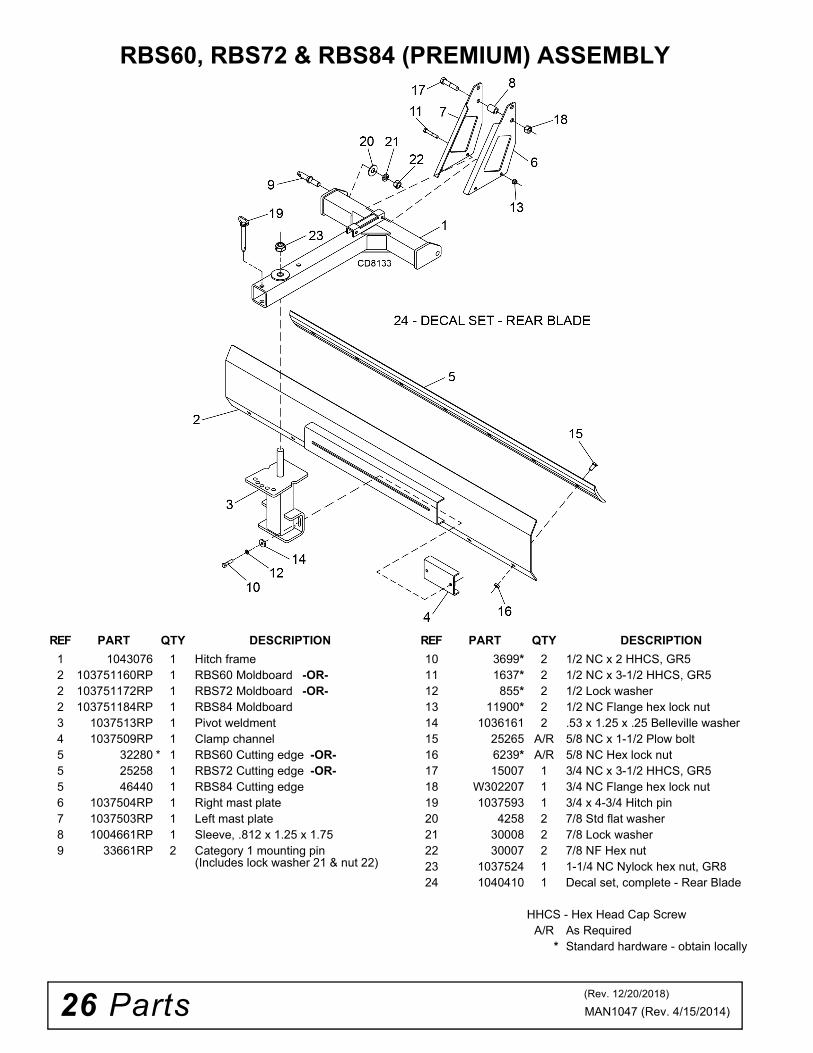
RBS60, RBS72 & RBS84 (PREMIUM) ASSEMBLY
REF PART QTY DESCRIPTION
1 1043076 1 Hitch frame2 103751160RP 1 RBS60 Moldboard -OR-2 103751172RP 1 RBS72 Moldboard -OR-2 103751184RP 1 RBS84 Moldboard 3 1037513RP 1 Pivot weldment4 1037509RP 1 Clamp channel5 32280 * 1 RBS60 Cutting edge -OR-5 25258 1 RBS72 Cutting edge -OR-5 46440 1 RBS84 Cutting edge6 1037504RP 1 Right mast plate7 1037503RP 1 Left mast plate8 1004661RP 1 Sleeve, .812 x 1.25 x 1.759 33661RP 2 Category 1 mounting pin
(Includes lock washer 21 & nut 22)
10 3699* 2 1/2 NC x 2 HHCS, GR511 1637* 2 1/2 NC x 3-1/2 HHCS, GR512 855* 2 1/2 Lock washer13 11900* 2 1/2 NC Flange hex lock nut14 1036161 2 .53 x 1.25 x .25 Belleville washer15 25265 A/R 5/8 NC x 1-1/2 Plow bolt16 6239* A/R 5/8 NC Hex lock nut17 15007 1 3/4 NC x 3-1/2 HHCS, GR518 W302207 1 3/4 NC Flange hex lock nut19 1037593 1 3/4 x 4-3/4 Hitch pin20 4258 2 7/8 Std flat washer21 30008 2 7/8 Lock washer22 30007 2 7/8 NF Hex nut23 1037524 1 1-1/4 NC Nylock hex nut, GR824 1040410 1 Decal set, complete - Rear Blade
HHCS - Hex Head Cap ScrewA/R As Required
* Standard hardware - obtain locally
REF PART QTY DESCRIPTION
(Rev. 12/20/2018)
Parts 27MAN1047 (Rev. 4/15/2014)
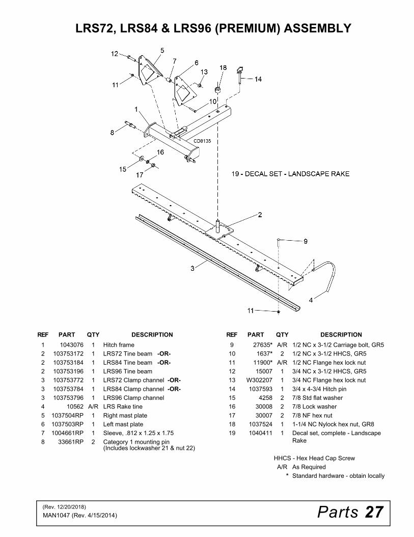
LRS72, LRS84 & LRS96 (PREMIUM) ASSEMBLY
REF PART QTY DESCRIPTION
1 1043076 1 Hitch frame
2 103753172 1 LRS72 Tine beam -OR-
2 103753184 1 LRS84 Tine beam -OR-
2 103753196 1 LRS96 Tine beam
3 103753772 1 LRS72 Clamp channel -OR-
3 103753784 1 LRS84 Clamp channel -OR-
3 103753796 1 LRS96 Clamp channel
4 10562 A/R LRS Rake tine
5 1037504RP 1 Right mast plate
6 1037503RP 1 Left mast plate
7 1004661RP 1 Sleeve, .812 x 1.25 x 1.75
8 33661RP 2 Category 1 mounting pin (Includes lockwasher 21 & nut 22)
9 27635* A/R 1/2 NC x 3-1/2 Carriage bolt, GR5
10 1637* 2 1/2 NC x 3-1/2 HHCS, GR5
11 11900* A/R 1/2 NC Flange hex lock nut
12 15007 1 3/4 NC x 3-1/2 HHCS, GR5
13 W302207 1 3/4 NC Flange hex lock nut
14 1037593 1 3/4 x 4-3/4 Hitch pin
15 4258 2 7/8 Std flat washer
16 30008 2 7/8 Lock washer
17 30007 2 7/8 NF hex nut
18 1037524 1 1-1/4 NC Nylock hex nut, GR8
19 1040411 1 Decal set, complete - Landscape Rake
HHCS - Hex Head Cap Screw
A/R As Required
* Standard hardware - obtain locally
REF PART QTY DESCRIPTION
(Rev. 12/20/2018)
28 Parts MAN1047 (Rev. 4/15/2014)
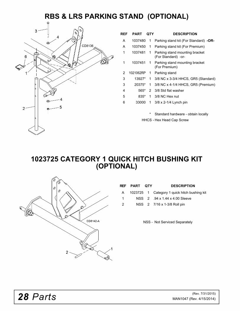
RBS & LRS PARKING STAND (OPTIONAL)
1023725 CATEGORY 1 QUICK HITCH BUSHING KIT (OPTIONAL)
REF PART QTY DESCRIPTION
A 1037480 1 Parking stand kit (For Standard) -OR-
A 1037450 1 Parking stand kit (For Premium)
1 1037481 1 Parking stand mounting bracket (For Standard) -or-
1 1037451 1 Parking stand mounting bracket (For Premium)
2 1021062RP 1 Parking stand
3 13927* 1 3/8 NC x 3-3/4 HHCS, GR5 (Standard)
3 20375* 1 3/8 NC x 4-1/4 HHCS, GR5 (Premium)
4 565* 2 3/8 Std flat washer
5 835* 1 3/8 NC Hex nut
6 33000 1 3/8 x 2-1/4 Lynch pin
* Standard hardware - obtain locally
HHCS - Hex Head Cap Screw
REF PART QTY DESCRIPTION
A 1023725 1 Category 1 quick hitch bushing kit
1 NSS 2 .94 x 1.44 x 4.00 Sleeve
2 NSS 2 7/16 x 1-3/8 Roll pin
NSS - Not Serviced Separately
(Rev. 7/31/2015)

Parts 29MAN1047 (Rev. 4/15/2014)
LRS TAIL WHEEL (OPTIONAL)
1004646 BASIC SKID SHOE KIT (OPTIONAL)
REF PART QTY DESCRIPTION
A 1037437 1 Tail wheel kit, LRS (Standard)
1 1037434RP 1 Tail wheel arm
2 1037435RP 1 Tail wheel clevis yoke
3 65129 3 Pipe, SCH 40 x .50, Spacer
4 66965 1 Wheel, 7.75 x 3.5 x .75 (Includes bearings item 5)
5 65577 2 Flange bearing, .75 x 1.415
6 29368 1 Sleeve, .50 x .75 x 3.38
7 62043* 1 1/4 x 1-3/4 Klik pin
8 3379* 3 1/2 NC x 1-1/2 HHCS, GR5
9 12305* 1 1/2 NC x 5-1/2 HHCS, GR5
10 63757RP 2 1/2 x 1-3/4 x 7 Ga Flat washer
11 11900* 4 1/2 NC Flange hex lock nut
12 31303 1 1-1/16 x 1-9/16 x 10 Ga Flat washer
* Standard hardware - obtain locally
HHCS - Hex Head Cap Screw
REF PART QTY DESCRIPTION
A 1004646 1 Skid shoe kit (Basic)
1 NSS 1 Skid Shoe
2 25266 1 5/8 NC x 2 Plow bolt
3 57817 1 5/8 Hardened flat washer
4 6239* 1 5/8 NC Hex lock nut
NSS - Not Serviced Separately
* Standard hardware - obtain locally
30 Parts MAN1047 (Rev. 4/15/2014)
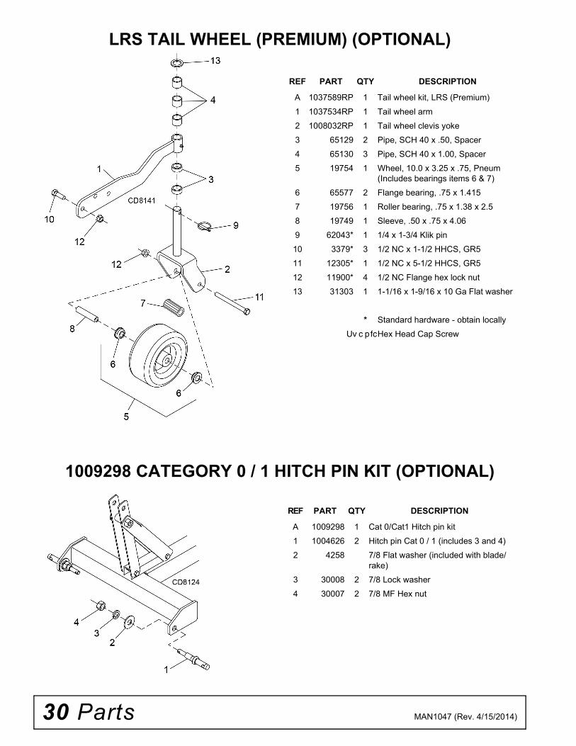
LRS TAIL WHEEL (PREMIUM) (OPTIONAL)
1009298 CATEGORY 0 / 1 HITCH PIN KIT (OPTIONAL)
REF PART QTY DESCRIPTION
A 1037589RP 1 Tail wheel kit, LRS (Premium)
1 1037534RP 1 Tail wheel arm
2 1008032RP 1 Tail wheel clevis yoke
3 65129 2 Pipe, SCH 40 x .50, Spacer
4 65130 3 Pipe, SCH 40 x 1.00, Spacer
5 19754 1 Wheel, 10.0 x 3.25 x .75, Pneum (Includes bearings items 6 & 7)
6 65577 2 Flange bearing, .75 x 1.415
7 19756 1 Roller bearing, .75 x 1.38 x 2.5
8 19749 1 Sleeve, .50 x .75 x 4.06
9 62043* 1 1/4 x 1-3/4 Klik pin
10 3379* 3 1/2 NC x 1-1/2 HHCS, GR5
11 12305* 1 1/2 NC x 5-1/2 HHCS, GR5
12 11900* 4 1/2 NC Flange hex lock nut
13 31303 1 1-1/16 x 1-9/16 x 10 Ga Flat washer
* Standard hardware - obtain locally
Uv c pfcHex Head Cap Screw
REF PART QTY DESCRIPTION
A 1009298 1 Cat 0/Cat1 Hitch pin kit
1 1004626 2 Hitch pin Cat 0 / 1 (includes 3 and 4)
2 4258 7/8 Flat washer (included with blade/rake)
3 30008 2 7/8 Lock washer
4 30007 2 7/8 MF Hex nut
Parts 31MAN1047 (Rev. 4/15/2014)
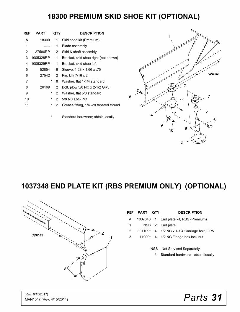
18300 PREMIUM SKID SHOE KIT (OPTIONAL)
1037348 END PLATE KIT (RBS PREMIUM ONLY) (OPTIONAL)
REF PART QTY DESCRIPTION
A 18300 1 Skid shoe kit (Premium)
1 ----- 1 Blade assembly
2 27586RP 2 Skid & shaft assembly
3 1005328RP 1 Bracket, skid shoe right (not shown)
4 1005329RP 1 Bracket, skid shoe left
5 52854 6 Sleeve, 1.28 x 1.66 x .75
6 27542 2 Pin, klik 7/16 x 2
7 * 8 Washer, flat 1-1/4 standard
8 26169 2 Bolt, plow 5/8 NC x 2-1/2 GR5
9 * 2 Washer, flat 5/8 standard
10 * 2 5/8 NC Lock nut
11 * 2 Grease fitting, 1/4 -28 tapered thread
* Standard hardware; obtain locally
REF PART QTY DESCRIPTION
A 1037348 1 End plate kit, RBS (Premium)
1 NSS 2 End plate
2 301109* 4 1/2 NC x 1-1/4 Carriage bolt, GR5
3 11900* 4 1/2 NC Flange hex lock nut
NSS - Not Serviced Separately
* Standard hardware - obtain locally
(Rev. 6/15/2017)

Bolt Torque & Size Charts (Rev. 3/28/2007)32 Appendix
BOLT TORQUE CHARTAlways tighten hardware to these values unless a different torque value or tightening procedure is listed for a specific application.
Fasteners must always be replaced with the same grade as specified in the manual parts list.
Always use the proper tool for tightening hardware: SAE for SAE hardware and Metric for metric hardware.
Make sure fastener threads are clean and you start thread engagement properly.
All torque values are given to specifications used on hardware defined by SAE J1701 MAR 99 & J1701M JUL 96.
Diameter (Inches)
WrenchSize
MARKING ON HEAD
SAE 2 SAE 5 SAE 8
lbs-ft N-m lbs-ft N-m lbs-ft N-m
1/4" 7/16" 6 8 10 13 14 18
5/16" 1/2" 12 17 19 26 27 37
3/8" 9/16" 23 31 35 47 49 67
7/16" 5/8" 36 48 55 75 78 106
1/2" 3/4" 55 75 85 115 120 163
9/16" 13/16" 78 106 121 164 171 232
5/8" 15/16" 110 149 170 230 240 325
3/4" 1-1/8" 192 261 297 403 420 569
7/8" 1-5/16" 306 416 474 642 669 907
1" 1-1/2" 467 634 722 979 1020 1383
Diameter & Thread Pitch (Millimeters)
Wrench Size
Coarse Thread Fine Thread
Diameter & Thread Pitch (Millimeters)
Marking on Head Marking on Head
Metric 8.8 Metric 10.9 Metric 8.8 Metric 10.9
N-m lbs-ft N-m lbs-ft N-m lbs-ft N-m lbs-ft
6 x 1.0 10 mm 8 6 11 8 8 6 11 8 6 x 1.0
8 x 1.25 13 mm 20 15 27 20 21 16 29 22 8 x 1.0
10 x 1.5 16 mm 39 29 54 40 41 30 57 42 10 x 1.25
12 x 1.75 18 mm 68 50 94 70 75 55 103 76 12 x 1.25
14 x 2.0 21 mm 109 80 151 111 118 87 163 120 14 x 1.5
16 x 2.0 24 mm 169 125 234 173 181 133 250 184 16 x 1.5
18 x 2.5 27 mm 234 172 323 239 263 194 363 268 18 x 1.5
20 x 2.5 30 mm 330 244 457 337 367 270 507 374 20 x 1.5
22 x 2.5 34 mm 451 332 623 460 495 365 684 505 22 x 1.5
24 x 3.0 36 mm 571 421 790 583 623 459 861 635 24 x 2.0
30 x 3.0 46 mm 1175 867 1626 1199 1258 928 1740 1283 30 x 2.0
A
SAE SERIES TORQUE CHART
SAE Bolt Head Identification
SAE Grade 2(No Dashes)
SAE Grade 5(3 Radial Dashes)
SAE Grade 8(6 Radial Dashes)
A
METRIC SERIES TORQUE CHART
Metric Bolt Head Identification
8.8
MetricGrade 10.9
10.9
MetricGrade 8.8
A
A A
Typical Washer Installations Lock Washer
Flat Washer
8/9/00
Bolt

Appendix 33Bolt Torque & Size Charts (Rev. 3/28/2007)
BOLT SIZE CHARTNOTE: Chart shows bolt thread sizes and corresponding head (wrench) sizes for standard SAE and metric bolts.
ABBREVIATIONSAG .............................................................. Agriculture
ASABE ....................American Society of Agricultural & Biological Engineers (formerly ASAE)
ASAE....... American Society of Agricultural Engineers
ATF............................... Automatic Transmission Fluid
BSPP.............................British Standard Pipe Parallel
BSPTM ................British Standard Pipe Tapered Male
CV ....................................................Constant Velocity
CCW.............................................. Counter-Clockwise
CW .............................................................. Clockwise
F .......................................................................Female
FT .............................................................. Full Thread
GA .....................................................................Gauge
GR (5, etc.) ........................................... Grade (5, etc.)
HHCS ........................................Hex Head Cap Screw
HT........................................................... Heat-Treated
JIC ............................. Joint Industry Council 37° Flare
LH.................................................................Left Hand
LT ...........................................................................Left
m ........................................................................ Meter
mm ............................................................... Millimeter
M ..........................................................................Male
MPa......................................................... Mega Pascal
N ......................................................................Newton
NC...................................................... National Coarse
NF ...........................................................National Fine
NPSM.....................National Pipe Straight Mechanical
NPT.......................................... National Pipe Tapered
NPT SWF.........National Pipe Tapered Swivel Female
ORBM ...........................................O-Ring Boss - Male
P........................................................................... Pitch
PBY...................................................... Power-Beyond
psi ......................................... Pounds per Square Inch
PTO.....................................................Power Take Off
QD.................................................... Quick Disconnect
RH.............................................................. Right Hand
ROPS........................... Roll-Over Protective Structure
RPM ........................................Revolutions Per Minute
RT ........................................................................Right
SAE..........................Society of Automotive Engineers
UNC ..................................................... Unified Coarse
UNF...........................................................Unified Fine
UNS ..................................................... Unified Special
5/16 3/8 1/2 5/8 3/4 7/8SAE Bolt Thread Sizes
MM 25 50 75 100 125 150 175
IN 1 7
Metric Bolt Thread Sizes8MM 18MM14MM12MM10MM 16MM
2 3 4 5 6

F-3079 (Rev. 11/13/2018)
WOODS®| A Blount International Brand2606 South Illinois Route 2 Post Office Box 1000Oregon, Illinois 61061 USA
800-319-6637 tel800-399-6637 faxwoodsequipment.com
WARRANTYAll Models Except Mow’n MachineTM Zero-Turn Mowers
Please Enter Information Below and Save for Future Reference.
Date Purchased: ____________________________ From (Dealer): __________________________________________
Model Number: ____________________________ Serial Number: __________________________________________
Woods Equipment Company (“WOODS”) warrants this product to be free from defect in material and workmanship. Except as otherwise set forthbelow, the duration of this Warranty shall be for TWELVE (12) MONTHS COMMENCING ON THE DATE OF DELIVERY OF THEPRODUCT TO THE ORIGINAL PURCHASER.
All current model backhoes, loaders and mounts (except 3-pt. SAF-T-LOK mounts) are warranted for two (2) years from the date of delivery tothe original purchaser. The limited warranty covers any defects in the material and/or workmanship. Following the proper, recommendedinstallation by an authorized Woods Dealer and normal use of a Woods mounting and backhoe or loader, if a tractor incurs damage resulting fromthe attachment, Woods will cover the existing tractor warranty in the event the manufacturer voids its tractor warranty because of the attachment.Warranty does not cover any misuse or abusive conditions that could cause premature wear or damage to attachment or tractor.
The warranty periods for specific parts or conditions are listed below:
Under no circumstances will this Warranty apply in the event that the product, in the good faith opinion of WOODS, has been subjected toimproper operation, improper maintenance, misuse, or an accident. This Warranty does not apply in the event that the product has beenmaterially modified or repaired by someone other than WOODS, a WOODS authorized dealer or distributor, and/or a WOODS authorizedservice center. This Warranty does not cover normal wear or tear, or normal maintenance items. This Warranty also does not cover repairs madewith parts other than those obtainable through WOODS.This Warranty is extended solely to the original purchaser of the product. Should the original purchaser sell or otherwise transfer this product toa third party, this Warranty does not transfer to the third party purchaser in any way. There are no third party beneficiaries of this Warranty.WOODS makes no warranty, express or implied, with respect to engines, batteries, tires or other parts or accessories not manufactured byWOODS. Warranties for these items, if any, are provided separately by their respective manufacturers.WOODS’ obligation under this Warranty is limited to, at WOODS’ option, the repair or replacement, free of charge, of the product if WOODS,in its sole discretion, deems it to be defective or in noncompliance with this Warranty. The product must be returned to WOODS with proofof purchase within thirty (30) days after such defect or noncompliance is discovered or should have been discovered, routed through thedealer and distributor from whom the purchase was made, transportation charges prepaid. WOODS shall complete such repair orreplacement within a reasonable time after WOODS receives the product. THERE ARE NO OTHER REMEDIES UNDER THIS WARRANTY.THE REMEDY OF REPAIR OR REPLACEMENT IS THE SOLE AND EXCLUSIVE REMEDY UNDER THIS WARRANTY.THERE ARE NO WARRANTIES WHICH EXTEND BEYOND THE DESCRIPTION ON THE FACE OF THIS WARRANTY. WOODSMAKES NO OTHER WARRANTY, EXPRESS OR IMPLIED, AND WOODS SPECIFICALLY DISCLAIMS ANY IMPLIED WARRANTYOF MERCHANTABILITY AND/OR ANY IMPLIED WARRANTY OF FITNESS FOR A PARTICULAR PURPOSE.WOODS shall not be liable for any incidental or consequential losses, damages or expenses, arising directly or indirectly from theproduct, whether such claim is based upon breach of contract, breach of warranty, negligence, strict liability in tort or any other legaltheory. Without limiting the generality of the foregoing, Woods specifically disclaims any damages relating to (i) lost profits, business, revenuesor goodwill; (ii) loss of crops; (iii) loss because of delay in harvesting; (iv) any expense or loss incurred for labor, supplies, substitute machineryor rental; or (v) any other type of damage to property or economic loss.This Warranty is subject to any existing conditions of supply which may directly affect WOODS’ ability to obtain materials or manufacturereplacement parts.No agent, representative, dealer, distributor, serviceperson, salesperson, or employee of any company, including without limitation, WOODS, itsauthorized dealers, distributors, and service centers, is authorized to alter, modify, or enlarge this Warranty. Answers to any questions regardingwarranty service and locations may be obtained by contacting:
Part or Condition
WarrantedModel Number
Duration (from date of delivery to the original
purchaser)
All units invoiced after 4/30/2012
Gearbox components
BB48X, BB60X, BB72X, BB84X, BB600X, BB720X, BB840X, BB6000X, BB7200X, BB8400X,DS12.50, TS14.60, DS1440, TS1680, DS8.30, DS10.40, DS8.50, DSO8.50, DS10.50, DSO10.50,DBH5.30, DBH6.30
6 years
BW12, BW15, BW126X, BW180X, BW126XHD, BW180XHD, BW1260X, BW1800XBW10.50, BW10.50Q, BW15.50, BW15.50Q, BW10.60, BW10.60Q, BW15.60, BW15.60Q,BW10.70, BW10.70Q, BW15.70, BW15.70Q
BW240X, BW240XHD, BW1620X, BW2400X
RD990X, PRD6000, PRD7200, PRD8400, S15CD, S20CD, S22CD, S25CD, S27CD, S30CD, TC/R74, TC/R68, TC/R60, TBW144, TBW180, TBW204, TSG50, S12ED, S15ED, S18ED, S20ED,TPD25, TPD35, TPD65, TPD95
RDC54, RD60, RD72, TBW150C, TS/R60, TS/R52, TS/R44, RC3.5, RC4, RC5, RC6 3 years (1 year if used in rental or commercial applications)
Blade spindles RD990X, PRD6000, PRD7200, PRD8400, TBW144, TBW180, TBW204 3 years

F-8494 (Rev. 11/12/2018)
©2019 Woods Equipment Company. All rights reserved. Woods® and the Woods logo are trademarks of Woods Equipment Company. All othertrademarks, trade names, or service marks not owned by Woods Equipment Company that appear in this manual are the property of their respectivecompanies or mark holders. Specifications subject to change without notice.
WOODS®| A Blount International Brand2606 South Illinois Route 2 Post Office Box 1000Oregon, Illinois 61061 USA
800-319-6637 tel800-399-6637 faxwoodsequipment.com
WARRANTY(Replacement Parts For All Models Except Zero-Turn Mowers)
Woods Equipment Company (“WOODS”) warrants this product to be free from defect in material andworkmanship for a period of ninety (90) days from the date of delivery of the product to the original purchaserwith the exception of V-belts, which will be free of defect in material and workmanship for a period of 12 months.
Under no circumstances will this Warranty apply in the event that the product, in the good faith opinion ofWOODS, has been subjected to improper operation, improper maintenance, misuse, or an accident. This Warrantydoes not cover normal wear or tear, or normal maintenance items.
This Warranty is extended solely to the original purchaser of the product. Should the original purchaser sell orotherwise transfer this product to a third party, this Warranty does not transfer to the third party purchaser in anyway. There are no third party beneficiaries of this Warranty.
WOODS’ obligation under this Warranty is limited to, at WOODS’ option, the repair or replacement, free ofcharge, of the product if WOODS, in its sole discretion, deems it to be defective or in noncompliance with thisWarranty. The product must be returned to WOODS with proof of purchase within thirty (30) days aftersuch defect or noncompliance is discovered or should have been discovered, routed through the dealer anddistributor from whom the purchase was made, transportation charges prepaid. WOODS shall completesuch repair or replacement within a reasonable time after WOODS receives the product. THERE ARE NOOTHER REMEDIES UNDER THIS WARRANTY. THE REMEDY OF REPAIR OR REPLACEMENT IS THESOLE AND EXCLUSIVE REMEDY UNDER THIS WARRANTY.
THERE ARE NO WARRANTIES WHICH EXTEND BEYOND THE DESCRIPTION ON THE FACE OF THISWARRANTY. WOODS MAKES NO OTHER WARRANTY, EXPRESS OR IMPLIED, AND WOODSSPECIFICALLY DISCLAIMS ANY IMPLIED WARRANTY OF MERCHANTABILITY AND/OR ANYIMPLIED WARRANTY OF FITNESS FOR A PARTICULAR PURPOSE.
WOODS shall not be liable for any incidental or consequential losses, damages or expenses, arising directlyor indirectly from the product, whether such claim is based upon breach of contract, breach of warranty,negligence, strict liability in tort or any other legal theory. Without limiting the generality of the foregoing,Woods specifically disclaims any damages relating to (i) lost profits, business, revenues or goodwill; (ii) loss ofcrops; (iii) loss because of delay in harvesting; (iv) any expense or loss incurred for labor, supplies, substitutemachinery or rental; or (v) any other type of damage to property or economic loss.
This Warranty is subject to any existing conditions of supply which may directly affect WOODS’ ability to obtainmaterials or manufacture replacement parts.
No agent, representative, dealer, distributor, service person, salesperson, or employee of any company, includingwithout limitation, WOODS, its authorized dealers, distributors, and service centers, is authorized to alter, modify,or enlarge this Warranty.
Answers to any questions regarding warranty service and locations may be obtained by contacting:

PART NO.
MAN1047
© 2019 Woods Equipment Company. All rights reserved. Woods® and the Woods logo are trademarks of Woods Equipment Company. All othertrademarks, trade names, or service marks not owned by Woods Equipment Company that appear in this manual are the property of their respec-tive companies or mark holders. Specifications subject to change without notice.
WOODS®| A Blount International Brand2606 South Illinois Route 2 Post Office Box 1000Oregon, Illinois 61061 USA
800-319-6637 tel800-399-6637 faxwoodsequipment.com