Embed Size (px)
Citation preview

REAR DRIVE SHAFT(3S−GTE ENGINE)COMPONENTS
−SUSPENSION AND AXLE Rear Drive Shaft (3S−GTE Engine)SA−52

REMOVAL OF REAR DRIVE SHAFT(See page SA−52)1. REMOVE ENGINE UNDER COVER2. DRAIN TRANSAXLE OIL3. REMOVE COTTER PIN, LOCK NUT CAP AND BEARING
LOCK NUT(a) Remove the cotter pin and lock nut cap.(b) With the parking brake engaged, remove the bearing lock
nut.4. LOOSEN SIX BOLTS HOLDING DRIVE SHAFT TO
DIFFERENTIAL SIDE GEAR SHAFT OR CENTERDRIVESHAFT
(a) Place matchmarks on the drive shaft and side gear shaft.NOTICE: Do not punch the marks.
Use paint, etc.(b) With the parking brake engaged, using SST, loosen the six
hexagon bolts.SST 09043−88010
HINT: Do not remove the bolts, finger tighten them not todrop down the drive shaft.5. REMOVE BRAKE CALIPERRemove the brake caliper from the axle carrier and suspendit with wire.6. REMOVE ROTOR DISCHINT: Before removing the rotor disc, place matchmarks onthe axle shaft and rotor disc.
NOTICE:
• The axle bearing could be damaged if it is subjectedto the vehicle weight, such as when moving the ve-hicle with the drive shaft removed. Therefore, if it isabsolutely necessary to place the vehicle weighton the axle bearing, first support it with SST.
SST 09570−22010, 09608−16041 (09608−02010)
• (w/ ABS)After disconnecting the drive shaft from the axlehub, work carefully so as not to damage the sensorrotor serrations on the drive shaft.
−SUSPENSION AND AXLE Rear Drive Shaft (3S−GTE Engine)SA−53
11. DISCONNECT DRIVE SHAFT FROM AXLE CARRIERUsing SST, disconnect the drive shaft from the axle carrier.SST 09950−20017
NOTICE:
• Cover the drive shaft boot with cloth to protect it fromdamage.
• (w/ ABS)Be careful not to damage the sensor rotor of thedrive shaft.
10. DISCONNECT TIE ROD END(a) Remove the tie rod end mounting bolt and nut, disconnect
the tie rod end from the rear axle carrier.(b) Similarly disconnect the other side.
9. DISCONNECT LOWER ARM FROM REAR AXLECARRIER
(a) Remove the two bolts holding the ball joint to the lowerarm.
(b) Disconnect the lower arm.
7. DISCONNECT STABILIZER LINKRemove the upper side nut from the stabilizer link.HINT: If the ball joint stud turns together with the nut,.use a hexagon wrench 5 mm (0.197 in.) to hold the stud.
8. (w/ ABS)REMOVE SPEED SENSOR FROM AXLE CARRIER
Remove the bolt and pull out the speed sensor.
−SUSPENSION AND AXLE Rear Drive Shaft (3S−GTE Engine)SA−54
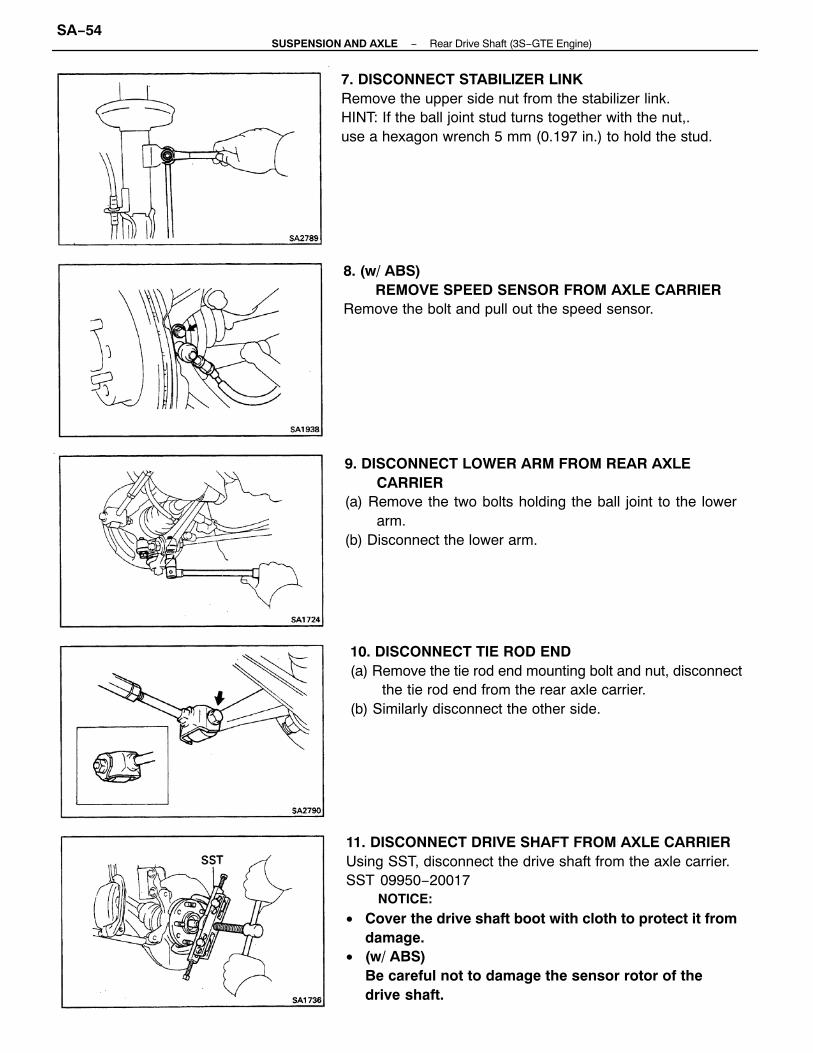
12. REMOVE LH DRIVE SHAFTUsing a hammer and brass bar, drive out the drive shaftfrom the transaxle.
NOTICE:
• Be careful not to damage the side gear shaft.• Be careful not to damage the differential side oilseal.
14. REMOVE DRIVE SHAFT BEARING BRACKET ANDBEARING BRACKET STAY
(a) Remove the two bolts, nut and the two bearing bracketstays from the bearing bracket and engine.
(b) Remove the two bolts and the bearing bracket from the en-gine.
(b) Remove the bolt from the bearing bracket.(c) Remove the R H drive shaft with center drive shaft.
NOTICE: Be careful not to damage the differentialside oil seal.
HINT: If it is hard to remove the bearing, use a brassbar and hammer and the drive flange end of the driveshaft.
13. REMOVE RH DRIVE SHAFT(a) Using a hammer and screwdriver, remove the snap ring
from the bearing bracket.
REPLACEMENT OF OIL SEAL1. REMOVE OIL SEALUsing SST, drive out the oil seal.SST 09308−00010
−SUSPENSION AND AXLE Rear Drive Shaft (3S−GTE Engine)SA−55

2. INSTALL NEW OIL SEAL(a) (LH)
Using SST and hammer, tap in a new LH oil seal.SST 09223−15010
(b) (R H)Using SST and hammer, tap in a new RH oil seal.SST 09316−60010 (09316−00010)
−SUSPENSION AND AXLE Rear Drive Shaft (3S−GTE Engine)SA−56

DISASSEMBLY OF REAR DRIVE SHAFT(See page SA−52)1. CHECK DRIVE SHAFT(a) Check to see that there is no play in the outboard joint.(b) Check to see that the inboard joint slides smoothly in the
thrust direction.(c) Check to see that there is no remarkable play in the radial
direction of the inboard joint.(d) Check for damage to boots.2. DISCONNECT SIDE GEAR SHAFT(a) Using SST, remove the six hexagon bolts and the three
washers.SST 09043−88010
(b) Disconnect the side gear shaft from the drive shaft.
3. REMOVE INBOARD JOINT AND BOOT CLAMPS(a) Mount the inboard joint sub−assembly in a vise.HINT:• Use a set of soft jaws in the vise to protect the inboard joint
sub−assembly.• Cover the outboard joint side dust cover with cloth to protect
it from damage.
(b) Using a screwdriver, remove the two inboard joint bootclamps.
(c) Remove the inboard joint boot from the inboard jointcover.
(c) Use bolts, nuts and washers to keep the inboard jointtogether.NOTICE: Tighten the bolts by hand to avoidscratching the flange surface.
−SUSPENSION AND AXLE Rear Drive Shaft (3S−GTE Engine)SA−57
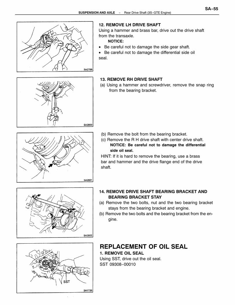
(e) Using a screwdriver, unstake the inboard joint cover.(f) Using a screwdriver, pry out the inboard joint from the
inboard joint cover.NOTICE: When lifting the inboard joint, hold onto theinner race and outer race.
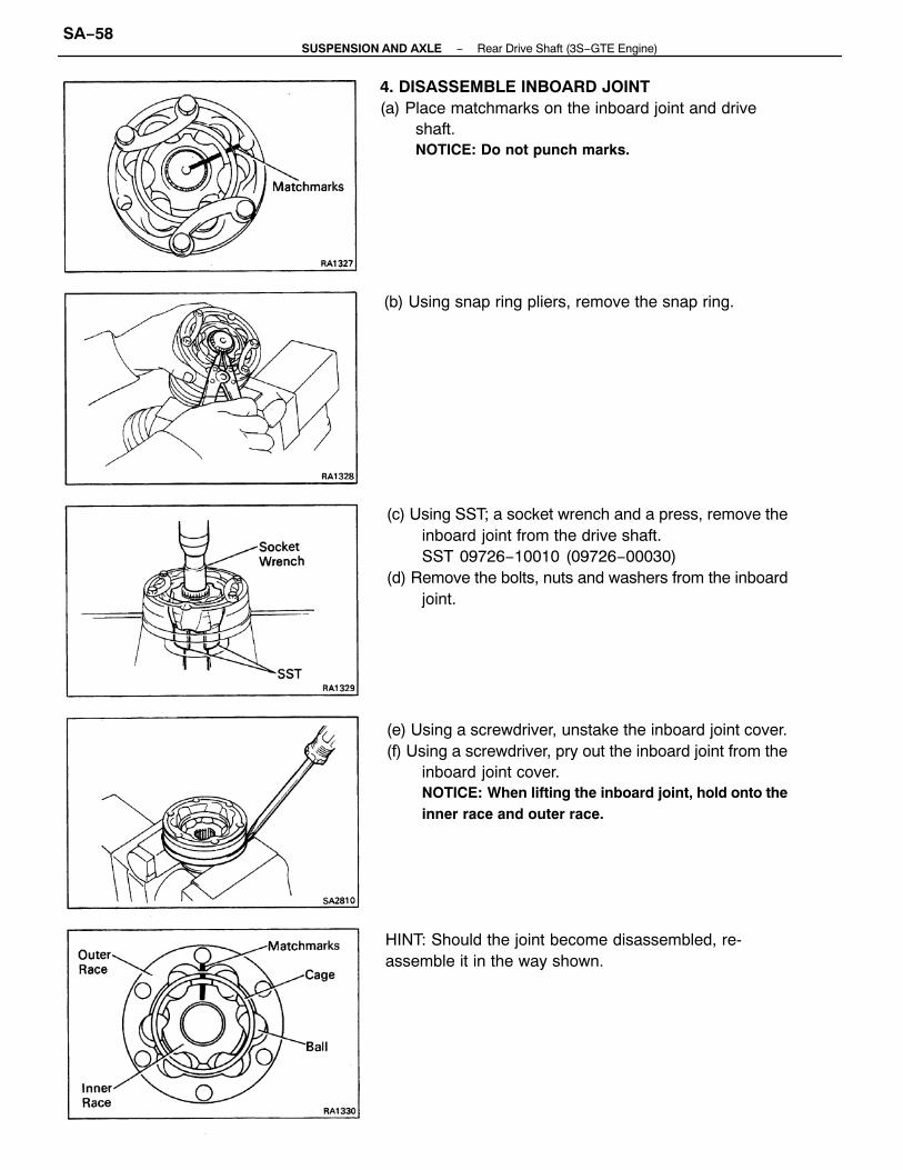
4. DISASSEMBLE INBOARD JOINT(a) Place matchmarks on the inboard joint and drive
shaft.NOTICE: Do not punch marks.
(c) Using SST; a socket wrench and a press, remove theinboard joint from the drive shaft.SST 09726−10010 (09726−00030)
(d) Remove the bolts, nuts and washers from the inboardjoint.
HINT: Should the joint become disassembled, re-assemble it in the way shown.
(b) Using snap ring pliers, remove the snap ring.
−SUSPENSION AND AXLE Rear Drive Shaft (3S−GTE Engine)SA−58

SERVICE HINT(a) Align the matchmarks place before disassembly.(b) Insert the spark plug wrench into the inner race.(c) Lift the outer race and cage, and insert the six balls.
6. REPLACE SIDE GEAR SHAFT SNAP RING(a) Using a screwdriver, pry out the snap ring.(b) Using snap ring pliers, install the new snap ring.
7. REMOVE DUST COVER FROM SIDE GEAR SHAFTUsing a screwdriver and hammer, tap out the dust cover.
(d) Jiggle the outer race and cage as shown to place theballs in their respective grooves.
(e) Lower the outer race and cage so that fit tightly withthe inner race.
5. REMOVE BOOTSRemove boots of the inboard joint and outboard joint.
−SUSPENSION AND AXLE Rear Drive Shaft (3S−GTE Engine)SA−59

10. REMOVE DUST COVER FROM CENTER DRIVESHAFTUsing SST and press, remove the dust cover from the in-board joint.SST 09950−00020
11. REMOVE BEARING FROM CENTER DRIVE SHAFT(a) Using snap ring pliers, remove the snap ring from the in-
board joint.
9. INSTALL DUST COVER TO SIDE GEAR SHAFTUsing a press, install a new dust cover.
8. REPLACE SIDE GEAR SHAFT O−RING(a) Using s screwdriver, remove the O−ring.
(b) Coat O−ring with MP grease.(c) Install a new 0−ring.
−SUSPENSION AND AXLE Rear Drive Shaft (3S−GTE Engine)SA−60
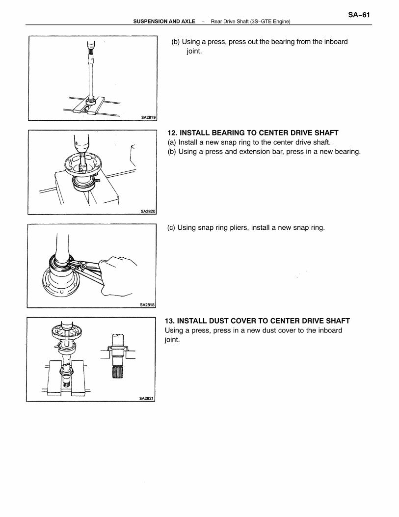
13. INSTALL DUST COVER TO CENTER DRIVE SHAFTUsing a press, press in a new dust cover to the inboardjoint.
12. INSTALL BEARING TO CENTER DRIVE SHAFT(a) Install a new snap ring to the center drive shaft.(b) Using a press and extension bar, press in a new bearing.
(b) Using a press, press out the bearing from the inboardjoint.
(c) Using snap ring pliers, install a new snap ring.
−SUSPENSION AND AXLE Rear Drive Shaft (3S−GTE Engine)SA−61
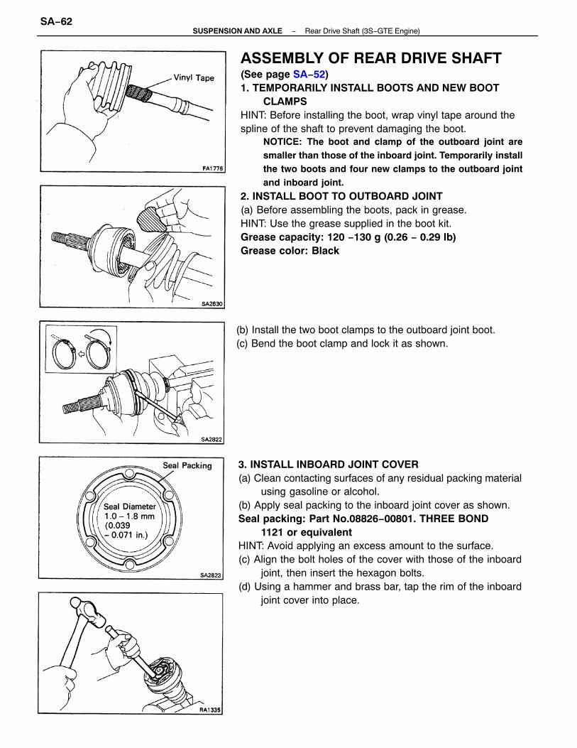
ASSEMBLY OF REAR DRIVE SHAFT(See page SA−52)1. TEMPORARILY INSTALL BOOTS AND NEW BOOT
CLAMPSHINT: Before installing the boot, wrap vinyl tape around thespline of the shaft to prevent damaging the boot.
NOTICE: The boot and clamp of the outboard joint aresmaller than those of the inboard joint. Temporarily installthe two boots and four new clamps to the outboard jointand inboard joint.
2. INSTALL BOOT TO OUTBOARD JOINT(a) Before assembling the boots, pack in grease.HINT: Use the grease supplied in the boot kit.Grease capacity: 120 −130 g (0.26 − 0.29 Ib)Grease color: Black
3. INSTALL INBOARD JOINT COVER(a) Clean contacting surfaces of any residual packing material
using gasoline or alcohol.(b) Apply seal packing to the inboard joint cover as shown.Seal packing: Part No.08826−00801. THREE BOND
1121 or equivalentHINT: Avoid applying an excess amount to the surface.(c) Align the bolt holes of the cover with those of the inboard
joint, then insert the hexagon bolts.(d) Using a hammer and brass bar, tap the rim of the inboard
joint cover into place.
(b) Install the two boot clamps to the outboard joint boot.(c) Bend the boot clamp and lock it as shown.
−SUSPENSION AND AXLE Rear Drive Shaft (3S−GTE Engine)SA−62

(e) Do this in the order shown, and repeat several time.(f) Use bolts, nuts and washers to keep the inboard joint to-
gether.NOTICE: Tighten the bolts by hand to avoid scratchingthe flange surface.
(b) Using a brass bar and hammer, tap the inboard jointonto the drive shaft.NOTICE: Make sure that the brass bar is touching theinner race, and not the cage.
(d) Pack in grease to the inboard tulip and boot.HINT: Use the grease supplied in the boot kit.Grease capacity: 90 −100 g (0.20 − 0.22 Ib)Grease color: Black
4. ASSEMBLE INBOARD JOINT(a) Align the matchmarks placed before disassembly.
(c) Using snap ring pliers, install a new snap ring.
−SUSPENSION AND AXLE Rear Drive Shaft (3S−GTE Engine)SA−63
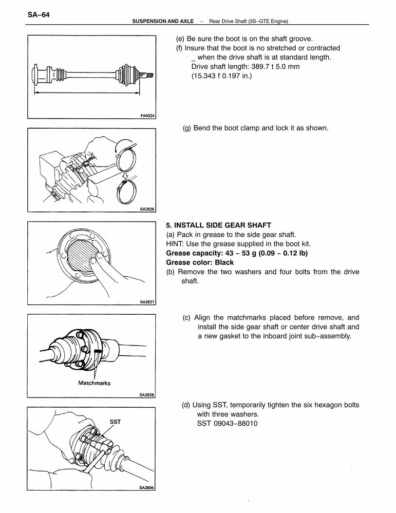
5. INSTALL SIDE GEAR SHAFT(a) Pack in grease to the side gear shaft.HINT: Use the grease supplied in the boot kit.Grease capacity: 43 − 53 g (0.09 − 0.12 Ib)Grease color: Black(b) Remove the two washers and four bolts from the drive
shaft.
(e) Be sure the boot is on the shaft groove.(f) Insure that the boot is no stretched or contracted
_ when the drive shaft is at standard length.Drive shaft length: 389.7 t 5.0 mm(15.343 f 0.197 in.)
(d) Using SST, temporarily tighten the six hexagon boltswith three washers.SST 09043−88010
(c) Align the matchmarks placed before remove, andinstall the side gear shaft or center drive shaft anda new gasket to the inboard joint sub−assembly.
(g) Bend the boot clamp and lock it as shown.
−SUSPENSION AND AXLE Rear Drive Shaft (3S−GTE Engine)SA−64
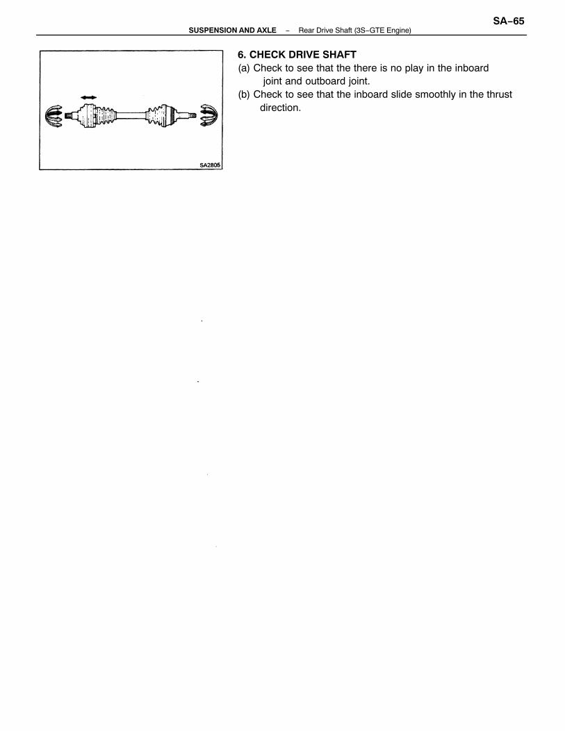
6. CHECK DRIVE SHAFT(a) Check to see that the there is no play in the inboard
joint and outboard joint.(b) Check to see that the inboard slide smoothly in the thrust
direction.
−SUSPENSION AND AXLE Rear Drive Shaft (3S−GTE Engine)SA−65

INSTALLATION OF REAR DRIVE SHAFT(See page SA−52)1. INSTALL DRIVE SHAFT BEARING BRACKET AND
BEARING BRACKET STAY(a) Install the bearing bracket to the engine with the twobolts.
Torque: 650 kg−cm (47 ft−Ib, 64 N−m)
(b) Install the two bearing bracket stays to the engine and bear-ing bracket with the two bolts and the nut.Torque:Bolt: 770 kg−cm (56 ft−Ib, 75 N−m)Nut: 770 kg−cm (56 ft−Ib, 75 N−m)
2. INSTALL LH DRIVE SHAFT(a) Apply the oil seal lip with MP grease.(b) Using a brass bar and hammer, drive in the drive shaft until
it makes contact with the pinion shaft.NOTICE: Be careful not to damage the boots.
HINT:• Before installing the drive shaft, set the snap ring opening
side facing downward.• Whether or not the drive shaft is making contact with the pin-
ion shaft can be known by sound or feeling when driving itin.
3. INSTALL RH DRIVE SHAFT(a) Apply M P grease to the transaxle oil lip.(b) Insert the center drive shaft with the RH drive shaft to the
transaxle through the bearing bracket.(c) Install the bolt to the bearing bracket.
Torque: 300 kg−cm (24 ft−Ib, 32 N−m)
(d) Using pliers, install the snap ring to the bearing bracket.
4. CONNECT OUTBOARD JOINT SIDE OF DRIVE SHAFTConnect the outboard joint side of the drive shaft to the axleshaft.
NOTICE:
• Be careful not to damage the boots.• (w/ ABS)
Be careful not to damage the sensor rotor of thedrive shaft.
−SUSPENSION AND AXLE Rear Drive Shaft (3S−GTE Engine)SA−66
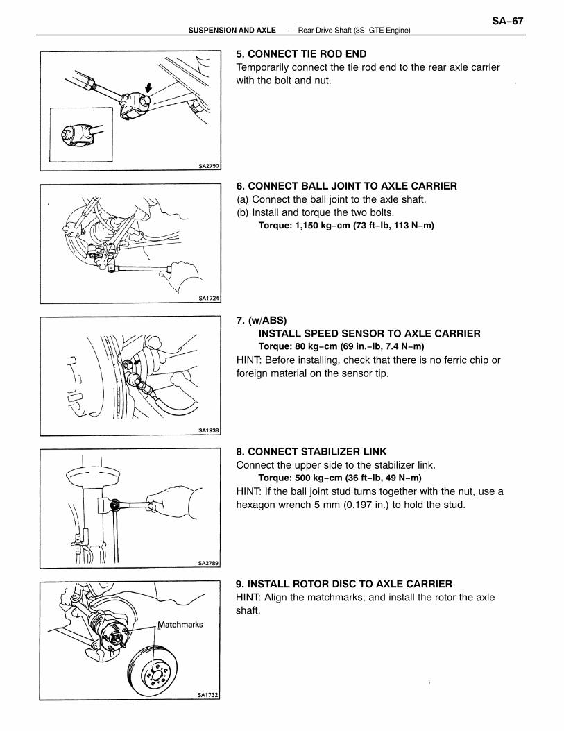
8. CONNECT STABILIZER LINKConnect the upper side to the stabilizer link.
Torque: 500 kg−cm (36 ft−Ib, 49 N−m)
HINT: If the ball joint stud turns together with the nut, use ahexagon wrench 5 mm (0.197 in.) to hold the stud.
7. (w/ABS)INSTALL SPEED SENSOR TO AXLE CARRIERTorque: 80 kg−cm (69 in.−Ib, 7.4 N−m)
HINT: Before installing, check that there is no ferric chip orforeign material on the sensor tip.
6. CONNECT BALL JOINT TO AXLE CARRIER(a) Connect the ball joint to the axle shaft.(b) Install and torque the two bolts.
Torque: 1,150 kg−cm (73 ft−Ib, 113 N−m)
5. CONNECT TIE ROD ENDTemporarily connect the tie rod end to the rear axle carrierwith the bolt and nut.
9. INSTALL ROTOR DISC TO AXLE CARRIERHINT: Align the matchmarks, and install the rotor the axleshaft.
−SUSPENSION AND AXLE Rear Drive Shaft (3S−GTE Engine)SA−67
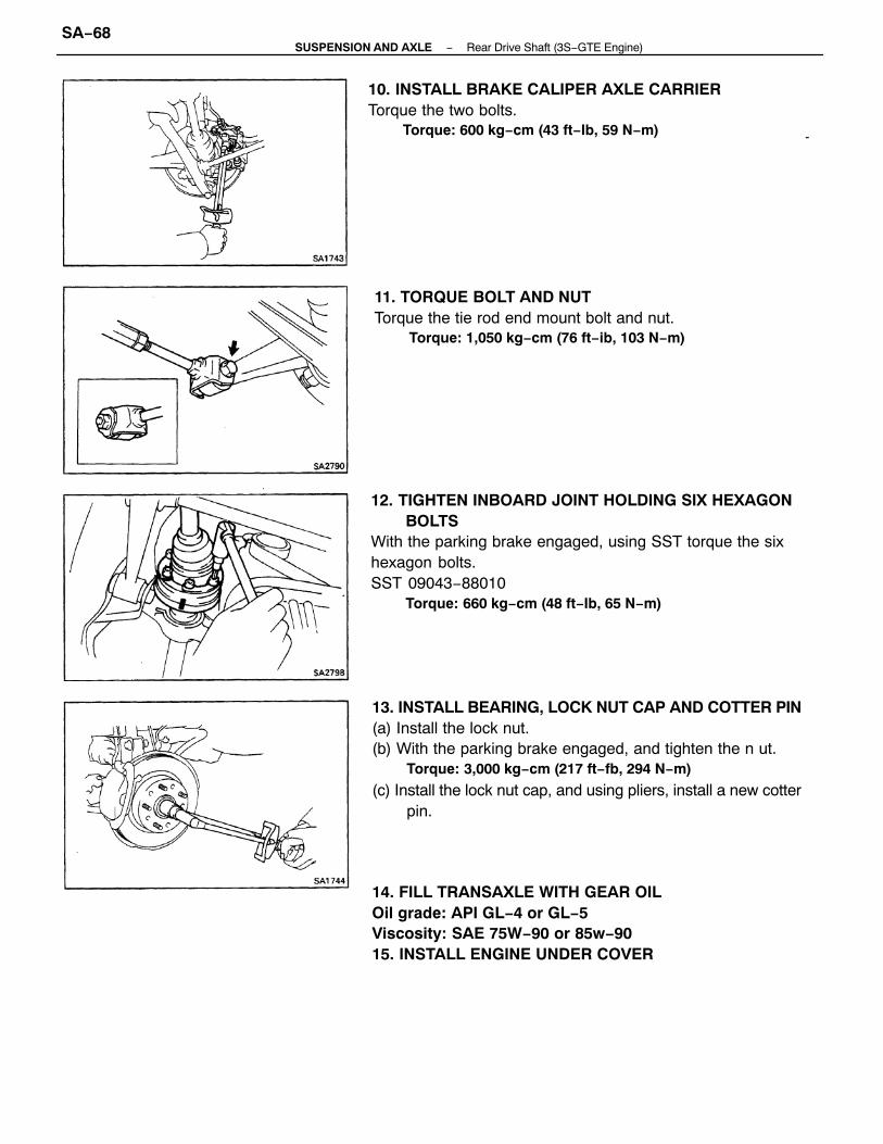
13. INSTALL BEARING, LOCK NUT CAP AND COTTER PIN(a) Install the lock nut.(b) With the parking brake engaged, and tighten the n ut.
Torque: 3,000 kg−cm (217 ft−fb, 294 N−m)
(c) Install the lock nut cap, and using pliers, install a new cotterpin.
12. TIGHTEN INBOARD JOINT HOLDING SIX HEXAGONBOLTS
With the parking brake engaged, using SST torque the sixhexagon bolts.SST 09043−88010
Torque: 660 kg−cm (48 ft−Ib, 65 N−m)
14. FILL TRANSAXLE WITH GEAR OILOil grade: API GL−4 or GL−5Viscosity: SAE 75W−90 or 85w−9015. INSTALL ENGINE UNDER COVER
10. INSTALL BRAKE CALIPER AXLE CARRIERTorque the two bolts.
Torque: 600 kg−cm (43 ft−Ib, 59 N−m)
11. TORQUE BOLT AND NUTTorque the tie rod end mount bolt and nut.
Torque: 1,050 kg−cm (76 ft−ib, 103 N−m)
−SUSPENSION AND AXLE Rear Drive Shaft (3S−GTE Engine)SA−68