Embed Size (px)
Citation preview
Dow
nloa
ded
from
asc
elib
rary
.org
by
Paul
Ow
ens
on 0
9/22
/15.
Cop
yrig
ht A
SCE
. For
per
sona
l use
onl
y; a
ll ri
ghts
res
erve
d.
REBAR CAGE CONSTRUCTIONAND SAFETY
BEST PRACTICES
Michael J. Casey, Ph.D., P.E.Girum S. Urgessa, Ph.D., P.E.
SPONSORED BY
the Construction Institute ofthe American Society of Civil Engineers
CONSTRUCTIONINSTITUTE
Published by the American Society of Civil Engineers
Dow
nloa
ded
from
asc
elib
rary
.org
by
Paul
Ow
ens
on 0
9/22
/15.
Cop
yrig
ht A
SCE
. For
per
sona
l use
onl
y; a
ll ri
ghts
res
erve
d.
Library of Congress Cataloging-in-Publication Data
Rebar cage construction and safety : best practices / Michael J. Casey, Ph.D., P.E., GirumS. Urgessa, Ph.D., P.E.; sponsored by the Construction Institute of the American Societyof Civil Engineers,
pages cmIncludes bibliographical references and index.ISBN 978-0-7844-1251-0 (pbk.) -- ISBN 978-0-7844-7699-4 (e-book) -- ISBN 978-0-
7844-7746-5 (epub)1. Reinforcing bars. 2. Reinforced concrete construction. I. Casey, Michael J. II.
Urgessa, Girum S. III. Construction Institute, sponsoring body.TA683.42.R38 2012624.1'8341-dc23
2012032072
Published by American Society of Civil Engineers1801 Alexander Bell DriveReston, Virginia, 20191-4400www.asce.org/pubs
Any statements expressed in these materials are those of the individual authors and donot necessarily represent the views of ASCE, which takes no responsibility for anystatement made herein. No reference made in this publication to any specific method,product, process, or service constitutes or implies an endorsement, recommendation,or warranty thereof by ASCE. The materials are for general information only and donot represent a standard of ASCE, nor are they intended as a reference in purchasespecifications, contracts, regulations, statutes, or any other legal document. ASCEmakes no representation or warranty of any kind, whether express or implied,concerning the accuracy, completeness, suitability, or utility of any information,apparatus, product, or process discussed in this publication, and assumes no liabilitytherefore. This information should not be used without first securing competentadvice with respect to its suitability for any general or specific application. Anyoneutilizing this information assumes all liability arising from such use, including but notlimited to infringement of any patent or patents.
ASCE and American Society of Civil Engineers—Registered in U.S. Patent andTrademark Office.
Photocopies and permissions. Permission to photocopy or reproduce material fromASCE publications can be obtained by sending an e-mail to [email protected] Tby locating a title in ASCE's online database (http://cedb.asce.org) and using the"Permission to Reuse" link.
Copyright © 2013 by the American Society of Civil Engineers.All Rights Reserved.ISBN 978-0-7844-1251-0 (paper)ISBN 978-0-7844-7699-4 (PDF)ISBN 978-0-7844-7746-5 (EPUB)Manufactured in the United States of America.
Dow
nloa
ded
from
asc
elib
rary
.org
by
Paul
Ow
ens
on 0
9/22
/15.
Cop
yrig
ht A
SCE
. For
per
sona
l use
onl
y; a
ll ri
ghts
res
erve
d.
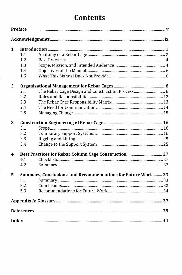
Contents
Preface v
Acknowledgments ix
1 Introduction 11.1 Anatomy of a Rebar Cage 21.2 Best Practices 41.3 Scope, Mission, and Intended Audience 41.4 Objectives of the Manual 61.5 What This Manual Does Not Provide 6
2 Organizational Management for Rebar Cages 82.1 The Rebar Cage Design and Construction Process 82.2 Roles and Responsibilities 122.3 The Rebar Cage Responsibility Matrix 132.4 The Need for Communication 142.5 Managing Change 15
3 Construction Engineering of Rebar Cages 163.1 Scope 163.2 Temporary Support Systems 163.3 Rigging and Lifting 253.4 Change to the Support System 25
4 Best Practices for Rebar Column Cage Construction 274.1 Checklists 274.2 Summary 32
5 Summary, Conclusions, and Recommendations for Future Work 335.1 Summary 335.2 Conclusions 335.3 Recommendations for Future Work 34
Appendix A: Glossary 37
References 39
Index 41
Dow
nloa
ded
from
asc
elib
rary
.org
by
Paul
Ow
ens
on 0
9/22
/15.
Cop
yrig
ht A
SCE
. For
per
sona
l use
onl
y; a
ll ri
ghts
res
erve
d.
Preface
Background
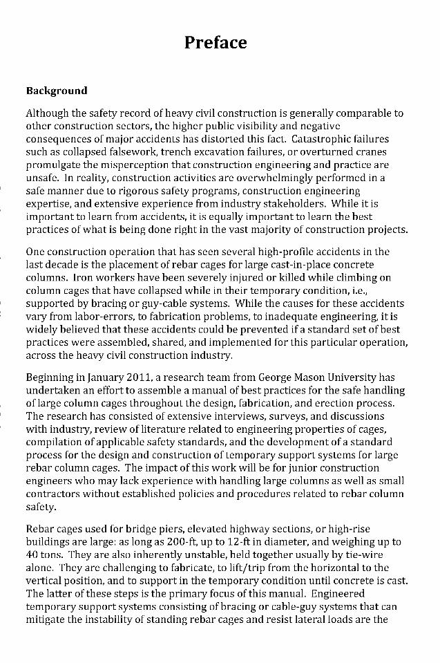
Although the safety record of heavy civil construction is generally comparable toother construction sectors, the higher public visibility and negativeconsequences of major accidents has distorted this fact. Catastrophic failuressuch as collapsed falsework, trench excavation failures, or overturned cranespromulgate the misperception that construction engineering and practice areunsafe. In reality, construction activities are overwhelmingly performed in asafe manner due to rigorous safety programs, construction engineeringexpertise, and extensive experience from industry stakeholders. While it isimportant to learn from accidents, it is equally important to learn the bestpractices of what is being done right in the vast majority of construction projects.
One construction operation that has seen several high-profile accidents in thelast decade is the placement of rebar cages for large cast-in-place concretecolumns. Iron workers have been severely injured or killed while climbing oncolumn cages that have collapsed while in their temporary condition, i.e.,supported by bracing or guy-cable systems. While the causes for these accidentsvary from labor-errors, to fabrication problems, to inadequate engineering, it iswidely believed that these accidents could be prevented if a standard set of bestpractices were assembled, shared, and implemented for this particular operation,across the heavy civil construction industry.
Beginning in January 2011, a research team from George Mason University hasundertaken an effort to assemble a manual of best practices for the safe handlingof large column cages throughout the design, fabrication, and erection process.The research has consisted of extensive interviews, surveys, and discussionswith industry, review of literature related to engineering properties of cages,compilation of applicable safety standards, and the development of a standardprocess for the design and construction of temporary support systems for largerebar column cages. The impact of this work will be for junior constructionengineers who may lack experience with handling large columns as well as smallcontractors without established policies and procedures related to rebar columnsafety.
Rebar cages used for bridge piers, elevated highway sections, or high-risebuildings are large: as long as 200-ft, up to 12-ft in diameter, and weighing up to40 tons. They are also inherently unstable, held together usually by tie-wirealone. They are challenging to fabricate, to lift/trip from the horizontal to thevertical position, and to support in the temporary condition until concrete is cast.The latter of these steps is the primary focus of this manual. Engineeredtemporary support systems consisting of bracing or cable-guy systems that canmitigate the instability of standing rebar cages and resist lateral loads are the
Dow
nloa
ded
from
asc
elib
rary
.org
by
Paul
Ow
ens
on 0
9/22
/15.
Cop
yrig
ht A
SCE
. For
per
sona
l use
onl
y; a
ll ri
ghts
res
erve
d.
best method for assuring the safety of iron workers tasked with climbing thecages for the placement of form work or other activities.
Among our own recommendations, we present numerous best practices usedboth formally and informally by heavy civil and rebar specialty contractors aswell as adopted from research activities investigating the stability of rebarcolumn cages. These are classified according to construction engineeringrecommendations and construction practice recommendations.
Major Construction Engineering Recommendations
• Any cage with a height/diameter ratio greater than 8, e.g. 24-ft exposedlength, 3-ft diameter, should be supported by an internal or external supportsystem.
• Internal rebar bracing, in the form of diagonal or box braces, can significantlyimprove the rigidity of a column cage. Lift/tripping operations andtemporary support systems are made substantially easier through enhancedcolumn rigidity provided by bracing.
• When used, support systems (braces, guy cables, or other systems) should bedesigned and stamped by a registered Professional Engineer.
• Support system design should account for cage self-weight, applicable lateralloads (environmental and pre-tensioning) and construction loads (includingpersonnel) with appropriate factors of safety.
• Appropriate structural analysis should be performed on the support systemtaking into account geometry of supports, column base condition (pinned orfixed), rigidity of the cage, and internal bracing.
• Guy wires, if used, should be placed symmetrically, ideally at 45-degreesinclination to the horizontal, but not more than 60-degrees.
• Anchor blocks (deadmen) shall be designed to resist overturning and sliding.• Once installed, the support system should not be removed or modified in any
way without the written approval of the responsible construction engineer.
Major Construction Practice Recommendations
• The overall goal should be to avoid or minimize the need for personnel toclimb on a column cage. Alternative access means such as with a mechanicallift are preferred if possible. No one should climb on an unsupported orunbraced column cage.
• Any design elements (dowels, flutes, etc.) or installation of bracing should bepre-fabricated before the cage is lifted/tripped to the vertical position.
• Cages should be protected from damage or deformation on the ground so asto avoid the need for personnel to climb cages to correct damage orfabrication errors.
• For cages over 20' - the suggested method of upending (tripping) would beto rig the cage in multiple locations (top - head, bottom and potentially themid-point(s) depending on length). This can be accomplished many ways,
Dow
nloa
ded
from
asc
elib
rary
.org
by
Paul
Ow
ens
on 0
9/22
/15.
Cop
yrig
ht A
SCE
. For
per
sona
l use
onl
y; a
ll ri
ghts
res
erve
d.
not limited to: using a single crane with a rolling block, using a single cranewith multiple load lines or with two cranes. Whichever method is utilized, itmust be analyzed to not overload the crane or load line with the leastcapacity. Upending (tripping) of cages over 20' should be reviewed andanalyzed by an individual with experience in lifting large rebar cages. Smallercages can usually be lifted/tripped with one crane.Once installed, temporary support systems should be verified by slackingcrane rigging and shaking the column. If any movement or deformation ofthe cage occurs, the crane should not be released and the constructionengineer should recommend corrections.Support systems, especially guy wires, should be clearly marked with flags orreflective material. All personnel should be instructed to avoid disrupting orremoving the support system unless supervised by the designingconstruction engineer.Support systems should be inspected regularly and verified that angles,tension, and placement of deadmen/anchor blocks are within tolerances.Support systems should only be altered/removed, e.g., for the placement offormwork, by experienced ironworkers and supervised by the designingconstruction engineer.
Dow
nloa
ded
from
asc
elib
rary
.org
by
Paul
Ow
ens
on 0
9/22
/15.
Cop
yrig
ht A
SCE
. For
per
sona
l use
onl
y; a
ll ri
ghts
res
erve
d.
Acknowledgments
The creation of this book was made possible by a grant from the ConstructionInstitute of the American Society of Civil Engineers. Their support is gratefullyacknowledged. The authors wish to acknowledge the assistance of two GMUstudents who performed research and compiled data for inclusion in thismanual, Mr. Y. Phillipe Douthard and Ms. Marie Stevens.
This manual was created through extensive dialogue with industry. The authorswish to acknowledge the following individuals and to thank them for theircontributions:
• Steve Shive, PE, President, ASCE Construction Institute and ExecutiveVice President, Kiewit Engineering Co., Omaha, NE.
• Jason McLear, Vice President, ASCE Construction Institute and DistrictManager for The LANE Construction Corp., Roanoke, TX.
• Brian Mapel, BMA Construction Engineers, Inc., Martinez, CA• Robert O'Neill and Jospeh Uva, Project Engineers, Skanska USA Civil
Northeast, Inc., New York, NY.• Ahmad Itani, Ph.D., PE, SE, Professor, University of Nevada, Reno, NV.• Lyle Sieg, P.Eng, Executive Vice President of Safety Operations, Harris
Rebar, Livermore, CA.• Robin Ko, PE, Chief Engineer, D. H. Charles Engineering, Inc. Cardiff by the
Sea, CA• Vincent A. Siefert, PE, Siefert Associates, Naugtauck, CT.• Howard Bennion, Pacific Coast Steel, Inc. Fairfield, CA.• Richard Feliciano, PE., Gorman Construction, Inc., Annapolis Junction, MD.• Neal Anderson, PE, SE, Vice President of Engineering, Concrete
Reinforcing Steel Institute, Schaumburg, IL.• John Brain, PE, Director of Engineering, Harsco Infrastructure, Fair Lawn,
NJ.• Scott Stevens, PE, President, Dimension Fabricators, Inc., Glennville, NY.• James Worrel, PE, President, Lift-Think, LLC, Raleigh, NC.• Carl Bilodeau, T.P., Director of Technical Services, Groupe Bellemare,
Montreal, Canada.• Alan T. Sheppard, PE, The Duross Group, Inc., Strongsville, OH.• Robert Stott, PE., Deputy Division Chief, Office of Structure Construction,
California Department of Transportation (CalTrans), Sacramento, CA.• Hart Keeble, Business Manager, International Association of Bridge,
Structural, Ornamental, and Reinforcing Iron Workers, Norwalk, CA.• Marvin Oey, Ph.D., PE, Director, ASCE Construction Institute, Reston, VA.• Katerina Lachinova, Board and Programs Specialist, ASCE Construction
Institute, Reston, VA.
Dow
nloa
ded
from
asc
elib
rary
.org
by
Paul
Ow
ens
on 0
9/22
/15.
Cop
yrig
ht A
SCE
. For
per
sona
l use
onl
y; a
ll ri
ghts
res
erve
d.
Chapter 1Introduction
Heavy civil construction for bridges and related infrastructure increasinglyrequires tall piers or columns. These cast-in-place concrete structures featuresteel reinforcing bar (rebar) cages that are typically fabricated horizontally(either on- or -off-site), lifted to the vertical position using one or more cranes,placed (either above grade or in a drilled shaft), then temporarily supporteduntil poured. A number of engineering and construction challenges are apparentin this process. First, while the permanent design for these columns accounts forall applicable vertical and lateral loads, applied loads in the temporary condition(i.e., the period up until the concrete is cast, sufficiently cured, and formworkremoved) are often not determined. Second, the lateral stability of rebar cagesin the temporary condition can be inadequate. Third, the design, placement, andeventual removal of the temporary support system are often not engineered.These and other errors have unfortunately contributed to numerous accidentsinvolving the collapse of rebar cages. The accidents have resulted in injuries,fatalities, and project delays. In California alone, fifty-six rebar cages collapsedin the period 1995 - 2010 (Builes-Mejia, Itani, & Sedarat, 2010). Nationally since2005, there have been at least three fatalities and dozens of serious injuries peryear related to rebar cage collapses on construction sites. These accidents mayhave been avoided if sufficient guidance for the safe handling of rebar cagesexisted.
Rebar cages are notoriously difficult to work with. Tall bridges or highway fly-overs can require columns up to 200 feet long and 12 feet in diameter.Reinforcing cages for these columns can weigh on the order of 40 tons and areusually required to be continuous (i.e., not lap spliced along the column length).The knowledge and expertise to successfully design, fabricate, lift, and supportsuch cages is distributed across a wide array of stakeholders, not all of whom areaware of each other's role in the process. Still, the successful design andconstruction of cast cast-in-place columns involving rebar cages is the norm, notthe exception. Hundreds of large column cages are placed safely every year inthe US alone. What is being done correctly in the majority of cases? Whatknowledge and expertise is being harnessed to safely erect large column cages?
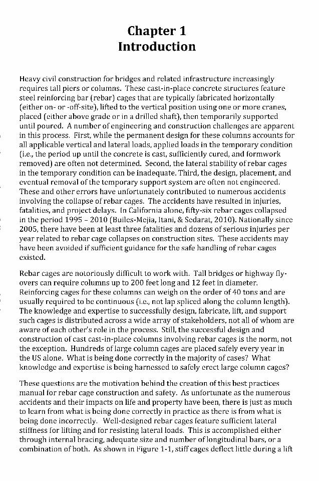
These questions are the motivation behind the creation of this best practicesmanual for rebar cage construction and safety. As unfortunate as the numerousaccidents and their impacts on life and property have been, there is just as muchto learn from what is being done correctly in practice as there is from what isbeing done incorrectly. Well-designed rebar cages feature sufficient lateralstiffness for lifting and for resisting lateral loads. This is accomplished eitherthrough internal bracing, adequate size and number of longitudinal bars, or acombination of both. As shown in Figure 1-1, stiff cages deflect little during a lift
Dow
nloa
ded
from
asc
elib
rary
.org
by
Paul
Ow
ens
on 0
9/22
/15.
Cop
yrig
ht A
SCE
. For
per
sona
l use
onl
y; a
ll ri
ghts
res
erve
d.
(trip) operation. Well-planned, and well-executed lifts include an adequatenumber and size of cranes as well as proper rigging and lift-support personnel.Once vertical, cages placed on grade or partially in shafts are sufficiently rigid ifan engineered, temporary support system such as symmetrically placed guywires is installed. Formwork and concrete pours are executed in such a way asto avoid or minimize disturbance of the support system. Construction workersare allowed to work on or around a cage only when engineering design of thesupport system is checked and health and safety plans are enforced. Takentogether, these engineering, planning, and execution steps constitute the bestpractices that this manual is intended to capture.
Figure 1-1: A bridge pier rebar cage being lifted into place for a Connecticuthighway project. (Photo courtesy of Dimension Fabricators, Inc. Reproduced with
permission)
1.1 Anatomy of a Rebar Cage
Rebar cages are usually craft-fabricated (i.e., by iron workers or craft labor) fromsteel reinforcing bars (#4 to as large as #18). The reinforcement will typicallyinclude concentric hoops (or spirals) along the length of the cage, which are tiedto longitudinal bars perpendicular to the hoops. Tying is done according todesign requirements, usually using Concrete Reinforcing Steel Institute (CRSI)standard methods (CRSI, 2005). Additionally, larger longitudinal bars ("pick-up") bars may be included to make the cage more rigid during a lift from the
Dow
nloa
ded
from
asc
elib
rary
.org
by
Paul
Ow
ens
on 0
9/22
/15.
Cop
yrig
ht A
SCE
. For
per
sona
l use
onl
y; a
ll ri
ghts
res
erve
d.
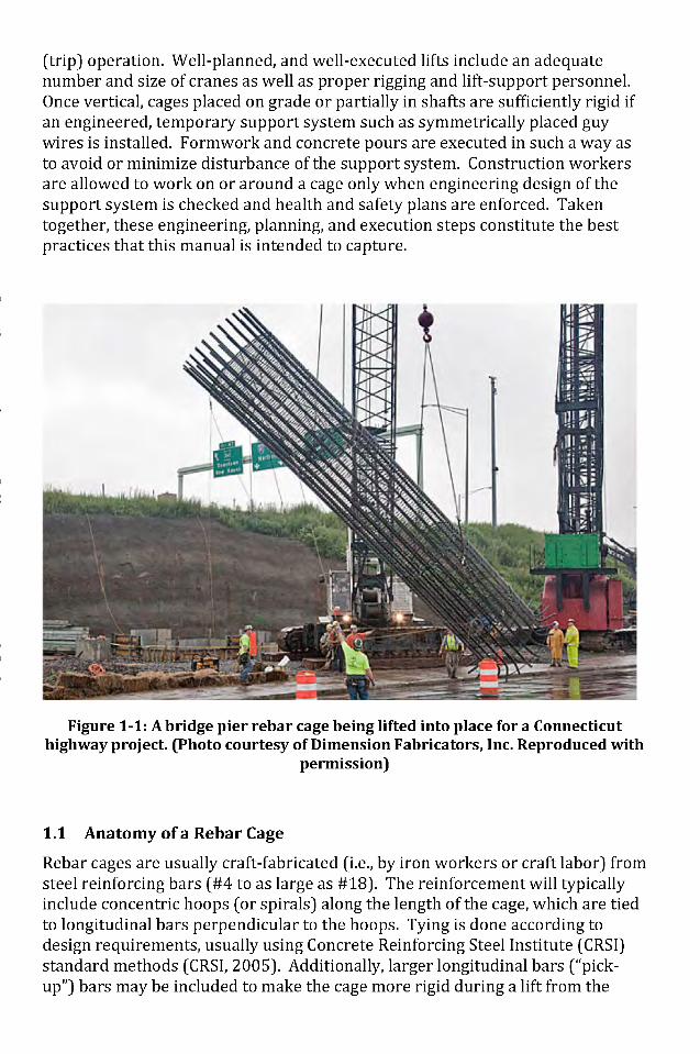
horizontal to the vertical position. Internal braces may be included to maintainthe proper spacing and orientation of longitudinal bars, prevent racking ordeformation during a lift, and to improve the cage's lateral stability in thevertical position. Internal braces may be of the "Z" type and placed in a "X"pattern when viewing the cross section of the cage.
Figure 1-2 shows the basic anatomy of a rebar cage for a vertical cast in placeconcrete column being temporarily supported by guy wires. Beginning at thebase and rising to the top, formwork is erected and concrete is poured insegments. Temporary supports are moved as necessary to accommodateformwork.
Figure 1-2: Anatomy of typical rebar cage for cast-in-place concrete column/pier.
Large rebar cages are also used in the construction of segmental slurry walls orin top- down construction. For these cages, the geometry is usually rectangularwith similar arrangement of longitudinal bars and perpendicular rectangularhoops. These cages, if placed entirely or mostly in a trench or drilled shaft, donot have a temporary support system.
Dow
nloa
ded
from
asc
elib
rary
.org
by
Paul
Ow
ens
on 0
9/22
/15.
Cop
yrig
ht A
SCE
. For
per
sona
l use
onl
y; a
ll ri
ghts
res
erve
d.
1.2 Best Practices
A best practice is a generally accepted, informally standardized method orprocess that has proven over time to accomplish a given task. Best practicestend to emerge from a community of organizations or individuals based onexperiential learning and sharing of knowledge. They rarely come from a singleauthority or viewpoint. A manual of best practices is a compendium of availableand accepted resources, guidelines, or procedures that is representative of thedomain and built from consensus.
This manual of best practices fits well with the above definition. It is based onresearch in the design and construction of rebar cages as practiced by a widecross-section of designers, fabricators, contractors, and iron workers. It is not astandard, nor is it intended to be prescriptive. Rather, this manual is a startingpoint for those individuals and organizations working with cages to developtheir own policies and procedures for appropriate temporary engineering andsafety methods during the construction process.
1.3 Scope, Mission, and Intended Audience
Construction safety is a broad topic and one that involves many constituents andinterests. While this manual deals with many safety standards and bestpractices, its scope is limited only to those related to rebar cages used for bridgepiers or other heavy civil applications. These columns are placed either on grade(on a footing pad, attached to dowels) or partially in a shaft such as a cast indrilled shaft (CIDH) pile with the majority of the column length above grade.
According to several industry experts, the lifting and temporary support of largerebar cages is amongst the most hazardous operations in heavy civilconstruction. This is due to their size, weight and their inherent instability. Thenegative consequences associated with the collapse of a rebar cage aresufficiently large to warrant specific guidance in the form of this document.When rebar column cages fail, they fail catastrophically usually with injury, lossof life, and significant project disruption.
The mission of this manual is to provide a reference document, drawn from awide swath of the heavy civil construction industry, that summarizes generalbest practices and engineering guidance for the handling of rebar cages.
Who should use this manual?The primary audience for the manual includes construction engineers workingin one of the following two roles:
1. Supervisory construction personnel responsible for constructionoperations for the builder or general contractor either directly or in aconsulting engineering capacity, or;
Dow
nloa
ded
from
asc
elib
rary
.org
by
Paul
Ow
ens
on 0
9/22
/15.
Cop
yrig
ht A
SCE
. For
per
sona
l use
onl
y; a
ll ri
ghts
res
erve
d.
2. Resident Engineers or EICs (Engineers in Charge) representing the ownerin a construction administration and/or inspection capacity.
For Number 1, the Engineer is assumed to have the responsibility and authorityfor the engineering design of the temporary support system and may also haveoversight of the lifting/trip operation. For Number 2, the Engineer is assumed tohave overall review and inspection authority in the context of life-safety andowner interests.
The secondary audience for this manual is all of the stakeholder roles in thedesign and construction of rebar cages. This includes structural engineers, andfabricators, rebar subcontractors, rigging and lifting personnel, iron workers, aswell as owners. Some Engineering knowledge is assumed (e.g., statics, forces,understanding of structure loadings), but all of these constituents should benefitto some degree from reading this manual.
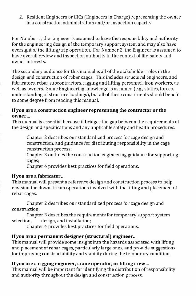
If you are a construction engineer representing the contractor or theowner...This manual is essential because it bridges the gap between the requirements ofthe design and specifications and any applicable safety and health procedures.
Chapter 2 describes our standardized process for cage design andconstruction, and guidance for distributing responsibility in the cageconstruction process;Chapter 3 outlines the construction engineering guidance for supportingcages;Chapter 4 provides best practices for field operations.
If you are a fabricator...This manual will present a reference design and construction process to helpenvision the downstream operations involved with the lifting and placement ofrebar cages.
Chapter 2 describes our standardized process for cage design andconstruction;
Chapter 3 describes the requirements for temporary support systemselection, design, and installation;
Chapter 4 provides best practices for field operations.
If you are a permanent designer (structural) engineer...This manual will provide some insight into the hazards associated with liftingand placement of rebar cages, particularly large ones, and provide suggestionsfor improving constructability and stability during the temporary condition.
If you are a rigging engineer, crane operator, or lifting crew...This manual will be important for identifying the distribution of responsibilityand authority throughout the design and construction process.
Dow
nloa
ded
from
asc
elib
rary
.org
by
Paul
Ow
ens
on 0
9/22
/15.
Cop
yrig
ht A
SCE
. For
per
sona
l use
onl
y; a
ll ri
ghts
res
erve
d.
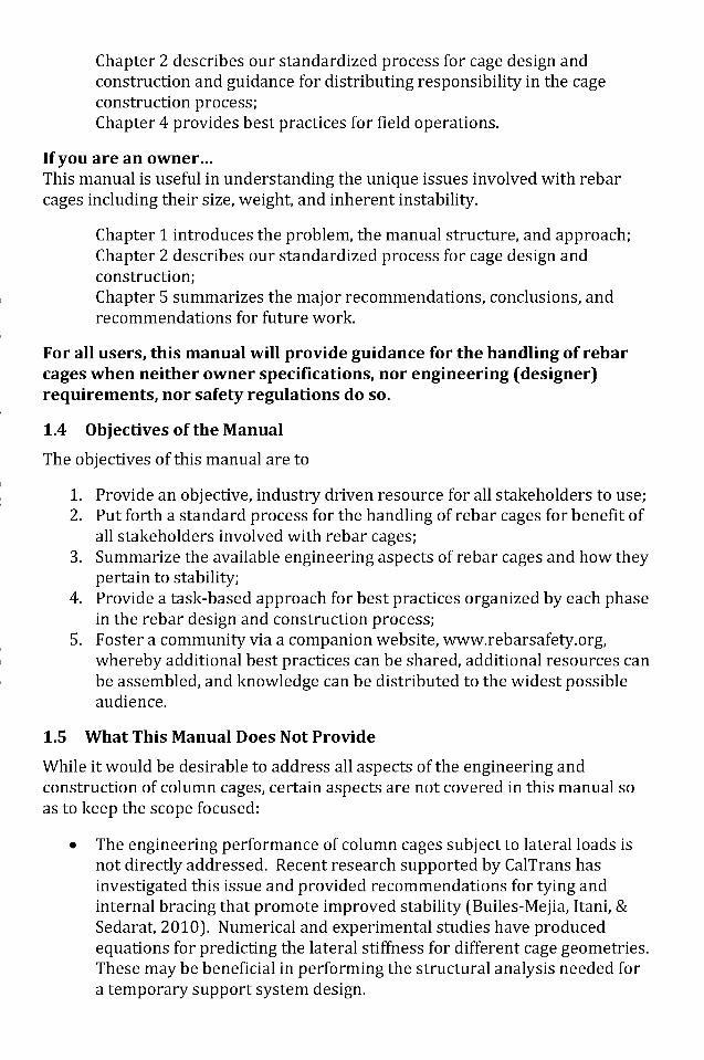
Chapter 2 describes our standardized process for cage design andconstruction and guidance for distributing responsibility in the cageconstruction process;Chapter 4 provides best practices for field operations.
If you are an owner...This manual is useful in understanding the unique issues involved with rebarcages including their size, weight, and inherent instability.
Chapter 1 introduces the problem, the manual structure, and approach;Chapter 2 describes our standardized process for cage design andconstruction;Chapter 5 summarizes the major recommendations, conclusions, andrecommendations for future work.
For all users, this manual will provide guidance for the handling of rebarcages when neither owner specifications, nor engineering (designer)requirements, nor safety regulations do so.
1.4 Ob j ectives of the Manual
The objectives of this manual are to
1. Provide an objective, industry driven resource for all stakeholders to use;2. Put forth a standard process for the handling of rebar cages for benefit of
all stakeholders involved with rebar cages;3. Summarize the available engineering aspects of rebar cages and how they
pertain to stability;4. Provide a task-based approach for best practices organized by each phase
in the rebar design and construction process;5. Foster a community via a companion website, www.rebarsafety.org,
whereby additional best practices can be shared, additional resources canbe assembled, and knowledge can be distributed to the widest possibleaudience.
1.5 What This Manual Does Not Provide
While it would be desirable to address all aspects of the engineering andconstruction of column cages, certain aspects are not covered in this manual soas to keep the scope focused:
• The engineering performance of column cages subject to lateral loads isnot directly addressed. Recent research supported by CalTrans hasinvestigated this issue and provided recommendations for tying andinternal bracing that promote improved stability (Builes-Mejia, Itani, &Sedarat, 2010). Numerical and experimental studies have producedequations for predicting the lateral stiffness for different cage geometries.These may be beneficial in performing the structural analysis needed fora temporary support system design.
Dow
nloa
ded
from
asc
elib
rary
.org
by
Paul
Ow
ens
on 0
9/22
/15.
Cop
yrig
ht A
SCE
. For
per
sona
l use
onl
y; a
ll ri
ghts
res
erve
d.
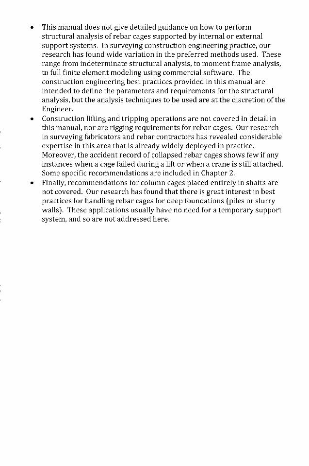
This manual does not give detailed guidance on how to performstructural analysis of rebar cages supported by internal or externalsupport systems. In surveying construction engineering practice, ourresearch has found wide variation in the preferred methods used. Theserange from indeterminate structural analysis, to moment frame analysis,to full finite element modeling using commercial software. Theconstruction engineering best practices provided in this manual areintended to define the parameters and requirements for the structuralanalysis, but the analysis techniques to be used are at the discretion of theEngineer.Construction lifting and tripping operations are not covered in detail inthis manual, nor are rigging requirements for rebar cages. Our researchin surveying fabricators and rebar contractors has revealed considerableexpertise in this area that is already widely deployed in practice.Moreover, the accident record of collapsed rebar cages shows few if anyinstances when a cage failed during a lift or when a crane is still attached.Some specific recommendations are included in Chapter 2.Finally, recommendations for column cages placed entirely in shafts arenot covered. Our research has found that there is great interest in bestpractices for handling rebar cages for deep foundations (piles or slurrywalls). These applications usually have no need for a temporary supportsystem, and so are not addressed here.
Dow
nloa
ded
from
asc
elib
rary
.org
by
Paul
Ow
ens
on 0
9/22
/15.
Cop
yrig
ht A
SCE
. For
per
sona
l use
onl
y; a
ll ri
ghts
res
erve
d.
Chapter 2Organizational Management for Rebar Cages
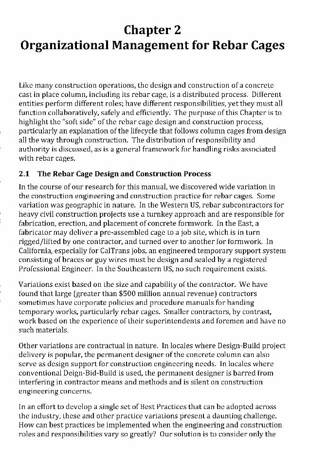
Like many construction operations, the design and construction of a concretecast in place column, including its rebar cage, is a distributed process. Differententities perform different roles; have different responsibilities, yet they must allfunction collaboratively, safely and efficiently. The purpose of this Chapter is tohighlight the "soft side" of the rebar cage design and construction process,particularly an explanation of the lifecycle that follows column cages from designall the way through construction. The distribution of responsibility andauthority is discussed, as is a general framework for handling risks associatedwith rebar cages.
2.1 The Rebar Cage Design and Construction Process
In the course of our research for this manual, we discovered wide variation inthe construction engineering and construction practice for rebar cages. Somevariation was geographic in nature. In the Western US, rebar subcontractors forheavy civil construction projects use a turnkey approach and are responsible forfabrication, erection, and placement of concrete formwork. In the East, afabricator may deliver a pre-assembled cage to a job site, which is in turnrigged/lifted by one contractor, and turned over to another for formwork. InCalifornia, especially for CalTrans jobs, an engineered temporary support systemconsisting of braces or guy wires must be design and sealed by a registeredProfessional Engineer. In the Southeastern US, no such requirement exists.
Variations exist based on the size and capability of the contractor. We havefound that large (greater than $500 million annual revenue) contractorssometimes have corporate policies and procedure manuals for handingtemporary works, particularly rebar cages. Smaller contractors, by contrast,work based on the experience of their superintendents and foremen and have nosuch materials.
Other variations are contractual in nature. In locales where Design-Build projectdelivery is popular, the permanent designer of the concrete column can alsoserve as design support for construction engineering needs. In locales whereconventional Deign-Bid-Build is used, the permanent designer is barred frominterfering in contractor means and methods and is silent on constructionengineering concerns.
In an effort to develop a single set of Best Practices that can be adopted acrossthe industry, these and other practice variations present a daunting challenge.How can best practices be implemented when the engineering and constructionroles and responsibilities vary so greatly? Our solution is to consider only the
Dow
nloa
ded
from
asc
elib
rary
.org
by
Paul
Ow
ens
on 0
9/22
/15.
Cop
yrig
ht A
SCE
. For
per
sona
l use
onl
y; a
ll ri
ghts
res
erve
d.
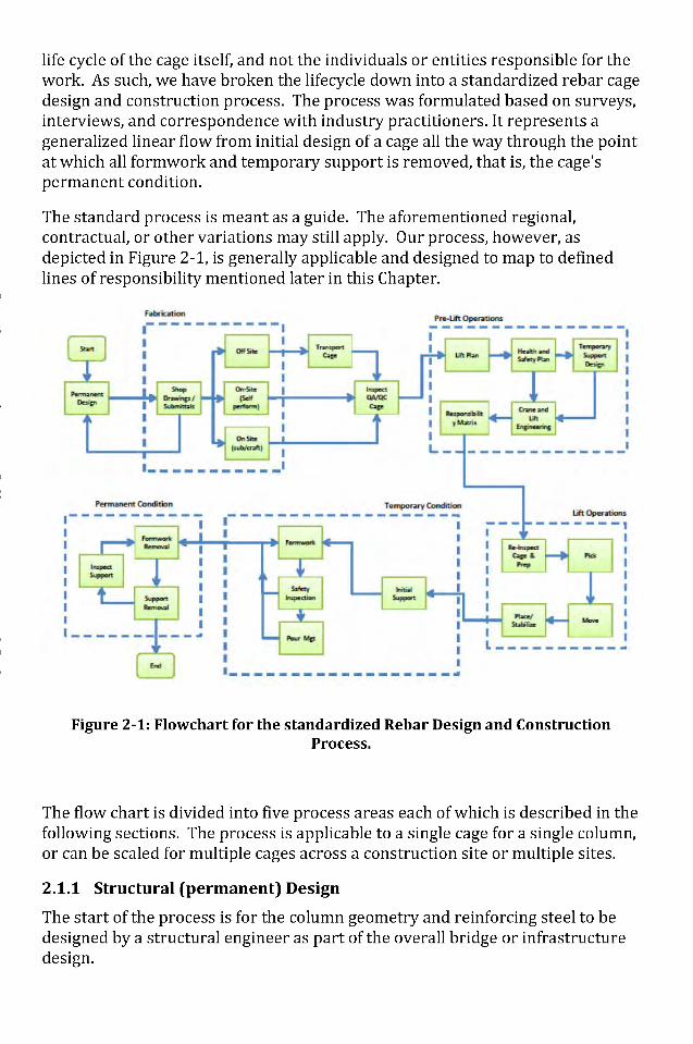
life cycle of the cage itself, and not the individuals or entities responsible for thework. As such, we have broken the lifecycle down into a standardized rebar cagedesign and construction process. The process was formulated based on surveys,interviews, and correspondence with industry practitioners. It represents ageneralized linear flow from initial design of a cage all the way through the pointat which all formwork and temporary support is removed, that is, the cage'spermanent condition.
The standard process is meant as a guide. The aforementioned regional,contractual, or other variations may still apply. Our process, however, asdepicted in Figure 2-1, is generally applicable and designed to map to definedlines of responsibility mentioned later in this Chapter.
Figure 2-1: Flowchart for the standardized Rebar Design and ConstructionProcess.
The flow chart is divided into five process areas each of which is described in thefollowing sections. The process is applicable to a single cage for a single column,or can be scaled for multiple cages across a construction site or multiple sites.
2.1.1 Structural (permanent) Design
The start of the process is for the column geometry and reinforcing steel to bedesigned by a structural engineer as part of the overall bridge or infrastructuredesign.
Dow
nloa
ded
from
asc
elib
rary
.org
by
Paul
Ow
ens
on 0
9/22
/15.
Cop
yrig
ht A
SCE
. For
per
sona
l use
onl
y; a
ll ri
ghts
res
erve
d.
It is uncommon for structural engineers to design bracing, reinforcement forlifting, or reinforcement for improved lateral stiffness in the temporarycondition. This will instead be done by a fabrication shop or rebarsubcontractor. Shop drawings with bracing, tying details, and additional pick-upreinforcement are submitted to the permanent designer and, once approved,become part of the permanent design.
At this point, the permanent designer is no longer involved in the process apartfrom review of inspection reports during the construction process. Thisdesigner should, however, be involved in a construability and coordinationreview to insure that the column/cage design is reasonable considering theconstraints of the site and that no unnecessary safety hazards are imparted onconstruction personnel due to the required lifting or placement of the cage. Wehave also identified some specific factors for the permanent designer toconsider:
1. We recommend that permanent designers allow for some internalbracing even if considered detrimental to the seismic performance of thecolumn.
2. We recommend that the permanent designer make clear the desired basecondition for the column in the plans and specs so that all "downstream"parties (fabricator, contractor, construction engineer) can planaccordingly.
2.1.2 Fabrication
Fabrication occurs next where the rebar cage is assembled either off-site at afabrication shop or on-site by iron workers employed by a rebar, bridge, orheavy civil subcontractor. Smaller cages assembled in fabrication shops areeasily transported to the site by tractor-trailers and have the advantages offactory quality control and just-in-time delivery for placement (i.e., no sitestaging required). A possible disadvantage is that, if these off-site suppliers ofpre-assembled cages play no role in lift (trip) operations, they may not detailcages for this purpose. Turnkey rebar subcontractors that provide bothfabrication and lift services are more likely to engineer cage details and liftrequirements concurrently.
For larger, more complicated cages or when mandated by local constructionpractice, on-site fabrication is necessary. Assembly and lifting may be done by asingle entity or by two entitles coordinated by the general contractor.
No matter the fabrication method, safety hazards from workers placing bars forthe cage assembly exist. Cage accidents have occurred during the fabricationprocess while still horizontal, and even in fabrication shops with experiencedpersonnel.
Upon completion of the fabrication process, inspection for verification of thereinforcing design is crucial. This may include:
Dow
nloa
ded
from
asc
elib
rary
.org
by
Paul
Ow
ens
on 0
9/22
/15.
Cop
yrig
ht A
SCE
. For
per
sona
l use
onl
y; a
ll ri
ghts
res
erve
d.
• Verification of all number, location and size of bars as designed by thestructural engineer and approved through applicable submittals by thefabricator.
• Verification of type and location of wire ties. Are ties of acceptablequality as per the permanent design/submittals?
• Quality assurance for the pre-lift cage condition. Was it assembled onlevel ground? Is it racked, twisted, or out of alignment?
• Have lift points been specified or clips installed and inspected for the lift?
The completion of the inspection process constitutes acceptance of thefabricated cage.
2.1.3 Pre-lift operations
Planning for lift operations for rebar cages can be done concurrently with thefabrication process.
An appropriate lift plan prepared by qualified rigging and crane operatingpersonnel is required. Lifts for rebar cages must first and foremost account forthe loads and geometry of the cage to be lifted, but also for anticipateddeflections and site interferences. In general, the ideal method for upending(tripping) any large cage is to use two cranes, one attached to the head end andthe other attached to the tail end. In situations where only one crane isavailable or when site conditions limit access for two cranes, crane model-specific guidance has been developed (Billodeau, 2010). In general, cages beinglifted by one crane shall use two lines, whereby the total weight being lifted bythe two lines must be less than the lesser capacity of either of the two lines. Asingle cage being lifted by two hooks is considered one load.
In addition to a detailed and appropriate lift plan, pre-lift operations requirereview of contractor or other health and safety plan information. Ideally theseplans describe how personnel are allowed to work on or around a cage duringthe lifting and erection process. The temporary support system design, to bediscussed in detail in Chapter 3, must be complete. It will include engineeringcalculations and checks based on the cage to be placed, the support systemrequired (e.g., symmetrical guy wires), and the constraints of the site.Coordination between the lift plan, health and safety plan, and temporarysupport system shall be done iteratively. This expands upon the normal levels ofapproval that are part of a standard lift plan to include roles and responsibilitiesthroughout the entire rebar design and construction process.
2.1.4 Lift-Operations
Detailed guidance on crane operations is beyond the scope of this manual. Thereader is referred to ASCE Policy 424 (Crane Safety on Construction Sites) andother applicable references.
Dow
nloa
ded
from
asc
elib
rary
.org
by
Paul
Ow
ens
on 0
9/22
/15.
Cop
yrig
ht A
SCE
. For
per
sona
l use
onl
y; a
ll ri
ghts
res
erve
d.
2.1.5 Temporary Condition
The temporary condition is arguably the most important part of the overallrebar cage process. This is because even highly engineered cages, lifts, andsupport systems can still result in collapse, injury, or death if the temporarysupports are changed, prematurely removed, or damaged.
The General Contractor is almost always responsible for the project underconstruction. He or she has ultimate supervisory control, unless the owner hasspecific requirements for temporary support (falsework) that require their ownindependent verification and inspection.
2.1.6 Permanent Construction
The culmination of the rebar design and construction process is a permanentcolumn capable of supporting its own weight, service loads, as well as lateralloads as per its design. For tall cages, the casting process for concrete issegmental. It is possible for the lower portions of a column to be consideredpermanent while any exposed length not cast in concrete is consideredtemporary. Numerous accidents have occurred for partially complete columnswhere the base of the column was cast. Vigilance and care is needed until theentire column is cast, formwork removed, and temporary support system (ifused) removed.
2.2 Roles and Responsibilities
The principles of responsibility and authority are described partly by standardconstruction practice and partly by the specific requirements of the constructioncontract. Lines of authority stem from the need to make decisions and giveapprovals on a project. Individual and organization responsibilities define whomust perform what specific actions. In terms of safety, the interplay of authorityand responsibility are tightest as they dictate the trade-off between resources tocomplete the work and protection of life, health, and property
Fisk and Reynolds (Fisk & Reynolds, 2010) provide a summary of theResponsibility and Authority as described by ASCE's 1975 survey (Goldbloom,1975).
An agency relationship is established in the contract documents between twoparties, typically the inspector/EIC and the owner (Fisk & Reynolds, 2010). TheEIC is charged with verifying the work for compliance with the contractdocuments and also for overall site safety. This is made possible through thedelegation of authority.
Roles of the inspector:
• Recognize when work is not being performed according to the plans andspecifications;
Dow
nloa
ded
from
asc
elib
rary
.org
by
Paul
Ow
ens
on 0
9/22
/15.
Cop
yrig
ht A
SCE
. For
per
sona
l use
onl
y; a
ll ri
ghts
res
erve
d.
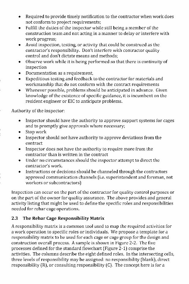
• Required to provide timely notification to the contractor when work doesnot conform to project requirements;
• Fulfill the duties of the inspector while still being a member of theconstruction team and not acting in a manner to delay or interfere withwork progress;
• Avoid inspection, testing, or activity that could be construed as thecontractor's responsibility. Don't interfere with contractor qualitycontrol and don't dictate means and methods;
• Observe work while it is being performed so that there is continuity ofinspection
• Documentation as a requirement,• Expeditious testing and feedback to the contractor for materials and
workmanship that do not conform with the contract requirements• Whenever possible, problems should be anticipated in advance. Given
knowledge of the existence of specific guidance, it is incumbent on theresident engineer or EIC to anticipate problems.
Authority of the inspector:
• Inspector should have the authority to approve support systems for cagesand to promptly give approvals where necessary;
• Stop work• Inspector should not have authority to approve deviations from the
contract• Inspector does not have the authority to require more from the
contractor than is written in the contract• Under no circumstances should the inspector attempt to direct the
contractor's work.• Instructions or decisions should be channeled through the contractors
approved communication channels (i.e. superintendent and foreman, notworkers or subcontractors)
Inspection can occur on the part of the contractor for quality control purposes oron the part of the owner for quality assurance. The above provides and generalactivity listing that might be used to define the specific roles and responsibilitiesneeded for rebar cage operations.
2.3 The Rebar Cage Responsibility Matrix
A responsibility matrix is a common tool used to map the required activities fora work operation to specific roles or individuals. We propose a template for aresponsibility matrix to be used for each cage or cage group for the design andconstruction overall process. A sample is shown in Figure 2-2. The fiveprocesses defined for the standard flowchart (Figure 2-1) comprise theactivities. The columns describe the eight defined roles. In the intersecting cells,three levels of responsibility maybe assigned: no responsibility (blank), directresponsibility (R), or consulting responsibility (C). The concept here is for a
Dow
nloa
ded
from
asc
elib
rary
.org
by
Paul
Ow
ens
on 0
9/22
/15.
Cop
yrig
ht A
SCE
. For
per
sona
l use
onl
y; a
ll ri
ghts
res
erve
d.
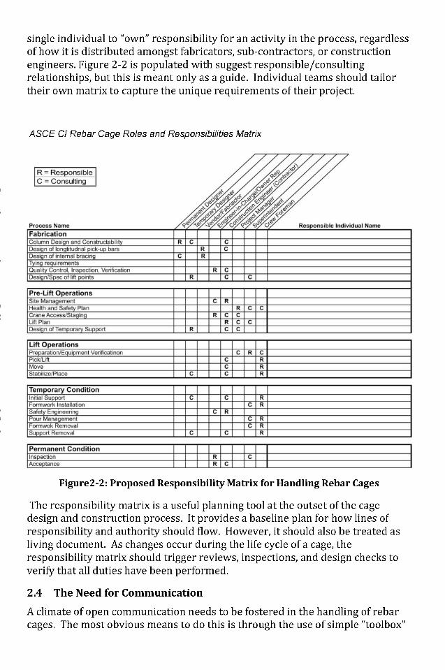
single individual to "own" responsibility for an activity in the process, regardlessof how it is distributed amongst fabricators, sub-contractors, or constructionengineers. Figure 2-2 is populated with suggest responsible/consultingrelationships, but this is meant only as a guide. Individual teams should tailortheir own matrix to capture the unique requirements of their project.
ASCE Cl Rebar Cage Roles and Responsibilities Matrix
Figure2-2: Proposed Responsibility Matrix for Handling Rebar Cages
The responsibility matrix is a useful planning tool at the outset of the cagedesign and construction process. It provides a baseline plan for how lines ofresponsibility and authority should flow. However, it should also be treated asliving document. As changes occur during the life cycle of a cage, theresponsibility matrix should trigger reviews, inspections, and design checks toverify that all duties have been performed.
2.4 The Need for Communication
A climate of open communication needs to be fostered in the handling of rebarcages. The most obvious means to do this is through the use of simple "toolbox"
Dow
nloa
ded
from
asc
elib
rary
.org
by
Paul
Ow
ens
on 0
9/22
/15.
Cop
yrig
ht A
SCE
. For
per
sona
l use
onl
y; a
ll ri
ghts
res
erve
d.
or "tailgate" meetings with all construction personnel who might be involvedwith the placing of a rebar cage on a particular day.
2.5 Managing Change
The fact that intricate plans for fabricating and erecting rebar cages can bechanged at the last minute needs to be considered. A responsibility matrix is animportant baseline, but it must also serve as active work control such that ifchanges to the cage, the lift, or to the temporary support system are made, thatthose changes are communicated throughout the members on the matrix.
Dow
nloa
ded
from
asc
elib
rary
.org
by
Paul
Ow
ens
on 0
9/22
/15.
Cop
yrig
ht A
SCE
. For
per
sona
l use
onl
y; a
ll ri
ghts
res
erve
d.
Chapter 3Construction Engineering of Rebar Cages
The previous chapter has discussed the overall process, roles, andresponsibilities involved in the design and construction of rebar cages forcolumns. This Chapter focuses on the construction engineering aspects and bestpractices for: 1) temporary support system selection, design, and installation,and; 2) the engineered installation, modification, and removal of the supportsystem.
3.1 Scope
The guidance herein is provided for pre-fabricated column rebar cages. Rebarcages for concrete columns generally have two applications, either entirely orpartially installed in a drilled shaft such as a CIDH (cast in drilled hole) pile, orplaced on-grade atop a footing or slab. Because of rebar cages' inherentinstability, the latter requires a temporary support system until concrete is castand cured, but the former does not.
Column cages with a height/diameter ratio of 8 or greater should be supported.Any cage that requires an iron worker to climb it for the placement of form workor other elements should be supported.
3.2 Temporary Support Systems
The engineering of a temporary support system for above grade column cages isdifficult due to the structural analysis of the semi-rigid cage. Lateral loadingconditions and site-constrained placement of bracing or guying are also achallenge. The process begins with load determination, followed by structuralanalysis, and then; design (including installation and modification plans ifrequired).
3.2.1 Determination of Loads
Service loads for the permanent conditions are determined as part of thepermanent design and are separate from the loads that impact a rebar cageduring construction. The load considerations for the design of a rebar cagesupport system should include the following and are based on ASCE Standard37-02 Design Loads on Structures During Construction:
• Dead loads- this includes the self-weight of the rebar cage. This can bedetermined from the fabricator's bill of lading for the cage, shopdrawings, or field estimates. If at anytime the support system will beattached to forms, the weight of those forms should be added to the self-weight of the cage.
Dow
nloa
ded
from
asc
elib
rary
.org
by
Paul
Ow
ens
on 0
9/22
/15.
Cop
yrig
ht A
SCE
. For
per
sona
l use
onl
y; a
ll ri
ghts
res
erve
d.
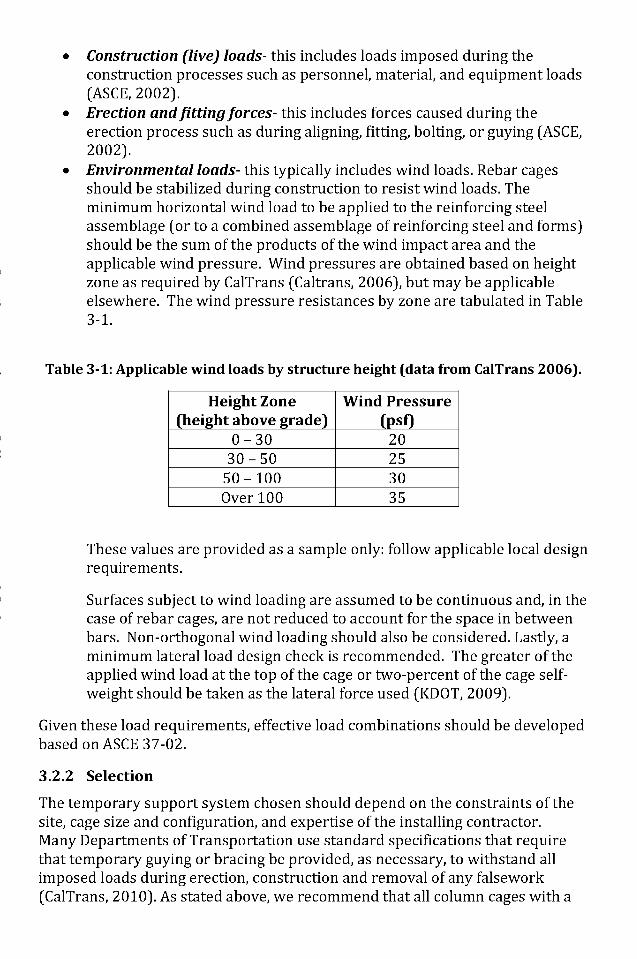
Construction (live) loads- this includes loads imposed during theconstruction processes such as personnel, material, and equipment loads(ASCE, 2002).Erection and fitting forces- this includes forces caused during theerection process such as during aligning, fitting, bolting, or guying (ASCE,2002).Environmental loads- this typically includes wind loads. Rebar cagesshould be stabilized during construction to resist wind loads. Theminimum horizontal wind load to be applied to the reinforcing steelassemblage (or to a combined assemblage of reinforcing steel and forms)should be the sum of the products of the wind impact area and theapplicable wind pressure. Wind pressures are obtained based on heightzone as required by CalTrans (Caltrans, 2006), but may be applicableelsewhere. The wind pressure resistances by zone are tabulated in Table3-1.
Table 3-1: Applicable wind loads by structure height (data from CalTrans 2006).
Height Zone(height above grade)
0-3030-50
50-100Over 100
Wind Pressure(psf)
20253035
These values are provided as a sample only: follow applicable local designrequirements.
Surfaces subject to wind loading are assumed to be continuous and, in thecase of rebar cages, are not reduced to account for the space in betweenbars. Non-orthogonal wind loading should also be considered. Lastly, aminimum lateral load design check is recommended. The greater of theapplied wind load at the top of the cage or two-percent of the cage self-weight should be taken as the lateral force used (KDOT, 2009).
Given these load requirements, effective load combinations should be developedbased on ASCE 37-02.
3.2.2 Selection
The temporary support system chosen should depend on the constraints of thesite, cage size and configuration, and expertise of the installing contractor.Many Departments of Transportation use standard specifications that requirethat temporary guying or bracing be provided, as necessary, to withstand allimposed loads during erection, construction and removal of any falsework(CalTrans, 2010). As stated above, we recommend that all column cages with a
Dow
nloa
ded
from
asc
elib
rary
.org
by
Paul
Ow
ens
on 0
9/22
/15.
Cop
yrig
ht A
SCE
. For
per
sona
l use
onl
y; a
ll ri
ghts
res
erve
d.
height/diameter ratio greater than or equal to 8 be supported. All engineeredsupport systems, regardless of the type used should be sealed and stamped by aProfessional Engineer. Support systems may be external, internal, or if the cageis sufficiently rigid, they may be omitted.
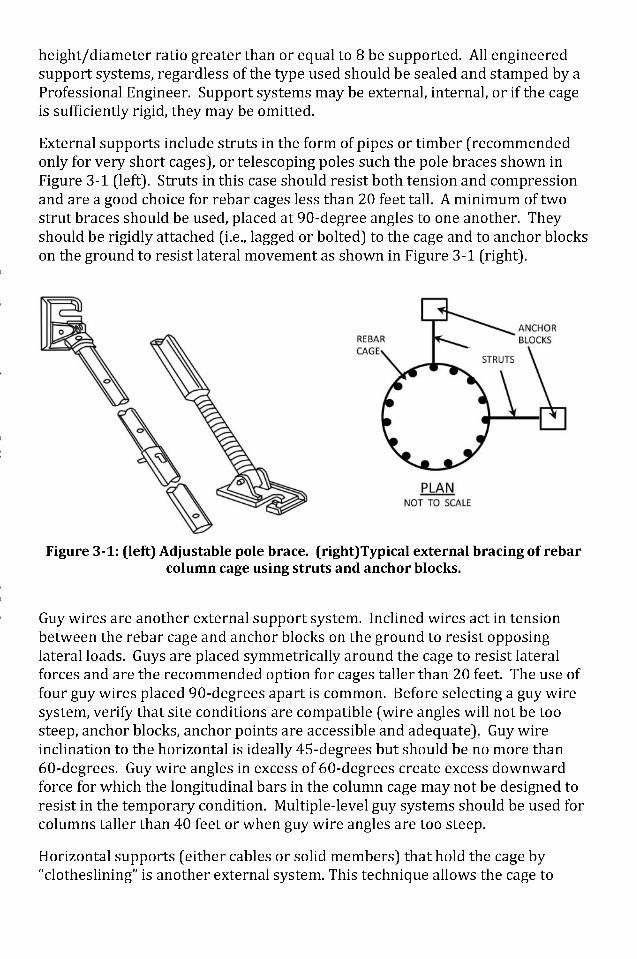
External supports include struts in the form of pipes or timber (recommendedonly for very short cages), or telescoping poles such the pole braces shown inFigure 3-1 (left). Struts in this case should resist both tension and compressionand are a good choice for rebar cages less than 20 feet tall. A minimum of twostrut braces should be used, placed at 90-degree angles to one another. Theyshould be rigidly attached (i.e., lagged or bolted) to the cage and to anchor blockson the ground to resist lateral movement as shown in Figure 3-1 (right).
Figure 3-1: (left) Adjustable pole brace, (right)Typical external bracing of rebarcolumn cage using struts and anchor blocks.
Guy wires are another external support system. Inclined wires act in tensionbetween the rebar cage and anchor blocks on the ground to resist opposinglateral loads. Guys are placed symmetrically around the cage to resist lateralforces and are the recommended option for cages taller than 20 feet. The use offour guy wires placed 90-degrees apart is common. Before selecting a guy wiresystem, verify that site conditions are compatible (wire angles will not be toosteep, anchor blocks, anchor points are accessible and adequate). Guy wireinclination to the horizontal is ideally 45-degrees but should be no more than60-degrees. Guy wire angles in excess of 60-degrees create excess downwardforce for which the longitudinal bars in the column cage may not be designed toresist in the temporary condition. Multiple-level guy systems should be used forcolumns taller than 40 feet or when guy wire angles are too steep.
Horizontal supports (either cables or solid members) that hold the cage by"clotheslining" is another external system. This technique allows the cage to
Dow
nloa
ded
from
asc
elib
rary
.org
by
Paul
Ow
ens
on 0
9/22
/15.
Cop
yrig
ht A
SCE
. For
per
sona
l use
onl
y; a
ll ri
ghts
res
erve
d.
hang from the horizontal supports as if being attached to a clothesline. This isapplicable only for relatively light cages and should not be the sole bracing used.
Internal support systems that are capable of supporting the rebar cage entirelyfrom within exist as well. These systems may be the only option for marineconstruction or where no external system can be anchored to the ground. Aninternal guying system consists of a rigid pipe or structural frame that supportsthe self-weight of the cage and resists lateral loads. Figure 3-2 shows anexample internal guying system for a bridge pier.
Finally, the Engineer may select no support system if the cage based on itsreinforcement design is sufficiently rigid and if the H/D ratio is low (e.g., lessthan 2). Rigidity can be enhanced in the cage through the inclusion of fabricator-installed internal bracing or field techniques that add strapping or spot welds.Such measures are subject to review and approval by the permanent designengineer as they may affect the engineering performance of the finished column.
It is common for multiple support system configurations to be selected/designedfor a given column and only the best alternative be implemented. It is alsocommon for hybrid systems that use a combination of external and internalsystems. Finally, the type and configuration of the support system may changeduring construction as concrete is cast and form work erected along the lengthof the cage.
3.2.3 Structural Analysis
Temporarily supported rebar cages subject to lateral loads are staticallyindeterminate structures. Determination of the resistance forces to lateral loadscan be achieved for braced or guy systems using established structural analysisprocedures. The standing rebar cage can be idealized as a beam-column system,but the lack or rigidity in the cage complicates the analysis. For best results,analysis using a finite element method software package is recommended. A 2D(assuming symmetrically placed braces/guys) or 3D analysis can be used tosolve for the needed resistance forces in the selected internal or externalsupport system. If the cage is assumed to be rigid, frame analysis may also beused.
The goal of the structural analysis is to determine the reaction forces at thetemporary supports and at the connections. Understanding of the basecondition of the column is important in selection and design of the supportsystem. Lap-spliced base connections (footing dowels tied to longitudinal bars)are idealized as pinned connections. Mechanically spliced base connections(with an approved mechanical rebar coupler) may be idealized as fixed. Pinnedconnections should be assumed if unspecified or unknown.
Dow
nloa
ded
from
asc
elib
rary
.org
by
Paul
Ow
ens
on 0
9/22
/15.
Cop
yrig
ht A
SCE
. For
per
sona
l use
onl
y; a
ll ri
ghts
res
erve
d.
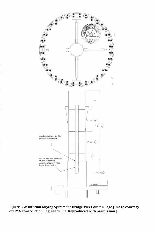
Figure 3-2: Internal Guying System for Bridge Pier Column Cage (Image courtesyof BMA Construction Engineers, Inc. Reproduced with permission.)
Dow
nloa
ded
from
asc
elib
rary
.org
by
Paul
Ow
ens
on 0
9/22
/15.
Cop
yrig
ht A
SCE
. For
per
sona
l use
onl
y; a
ll ri
ghts
res
erve
d.
It is common practice to perform the structural analysis based only on the grossgeometry of the cage and constituent number and size of bars. Internal bracingadded by a fabricator or rebar sub contractor is usually not accounted for andmay improve the rigidity of the column. Consequently, a conservative estimateof resistance forces needed in the support system may result.
3.2.4 Design
The design of the temporary support system involves sizing of thebracing/guying components and determining the configuration of anchor blocks.Only design considerations for bracing/guying systems are presented here.Internal guying using pipes or internal frames is relatively rare and uses morespecific structural design steps.
Bracing or guying systems are designed to resist combined axial and bendingaction of the rebar cage subject to lateral loads. Appropriate design guidanceshould be sought from the most recent AISC Steel Construction Manual or otherappropriate reference for steel beam-columns. Rebar for column cages areslender with slenderness ratio KL/r > 200. The effective length for design is thelongitudinal distance between support points or the length of the cage if only asingle tier of bracing is used. All of the longitudinal bars can be used to resist thebending moment, but only 25% of the vertical bars should be used for transfer ofaxial loads from a brace or guy cable (assuming four braces or guys).
Design of Bracing Support SystemsAs mentioned earlier, bracing (tension and compression) support systems areappropriate for columns less than 20 feet tall with H/D > 8. A minimum of twostrut braces placed 90-degrees apart is recommended. Struts must bemechanically attached to rebar cage and anchor blocks, and locked fromexpansion of contraction if telescoping poles are used. They should be lagged orbolted to the rebar cage at two-thirds the height or higher. At the height of thebrace, a horizontal "wagon wheel" element is recommended for transferringlateral loads through the column section.
Braces should be mechanically attached to the longitudinal bars, or if used, to thelarger pick-up bars. Fixed strut braces should be installed at an angle to thehorizontal not greater than 45-degrees. Appropriate factors of safety should beused in designing the brace system. A compressive/tensile force factor of safetyof 1.5 is recommended.
Design of Guy Wire Support SystemsNumerous design considerations are required for guy wire systems. Based onthe structural analysis and factors of safety, appropriate number and size of guywires should be specified.
Note that not more than 25% of total longitudinal bars should be used totransfer axial loads from one guy cable. The pre-tension and/or cable drape
Dow
nloa
ded
from
asc
elib
rary
.org
by
Paul
Ow
ens
on 0
9/22
/15.
Cop
yrig
ht A
SCE
. For
per
sona
l use
onl
y; a
ll ri
ghts
res
erve
d.
should be specified as well which may require catenary analysis depending onthe gauge of guy cable specified.
Guy wires should be placed symmetrically (i.e., opposite one another, in evennumbers). Four cables separated 90-degrees from one another is a commonconfiguration. Asymmetrical configurations are possible, but may result intwisting of the cage due to torsional stress when cables are moved for theplacement of formwork.
When rebar cages exceed 30 feet tall, multiple levels of guy wires arerecommended. Spacing for multiple levels of guy wires is recommended at 20feet with no more than 20 feet of unsupported length. Guy wires should beplaced at the top of the cage if possible, but no lower than 2/3 of the cage heightmeasured from the bottom. The multiple levels should all be in the same verticalplane for each guy wire group and can be attached to the same or multipleanchor blocks. Multiple levels of guy wires provide greater lateral support, butalso provide redundancy in the event that a higher or lower guy cable isremoved or damaged.
As already stated, guy wires, when tensioned, introduce downward compressiveforce on the cage, guy wire angles need to be controlled. Guy wires are ideally 45degrees inclined to the horizontal, but not more than 60 degrees. Multiple levelsof guy wires promote higher, more desirable wire angles.
Cable pre-tension requirements should also be satisfied and this is determinedby an allowable drape. The weight, length of cable, and pretension force areused to determine the drape of the cable. Pre-tensioning will stretch out slack inthe guy wires. The amount of pre-tensioning depends on the type of guy wiresand the effective height of the guy wire location compared to the rebar cage.Applying a large pre-tension load will reduce the ability of the guy wire toabsorb additional load before it reaches the breaking strength (Gantes, Khoury,Connor, & Pouangare, 1993). A pre-tension load often to fifteen percent of theultimate breaking strength of guy wires is recommended. The guy wire shouldnot be designed up to its breaking strength and an appropriate factor of safetyshould be included to obtain an allowable strength value.
For long cables, or for cables requiring larger than normal pre-tension, designchecks should be performed for thermal effects on guy wire stress. Periodicwind or other forces can also cause "galloping" guy cables, a situation thatshould be avoided.
Guy wires should be a minimum of 3/8" IWRC braided steel wire or EHC guywire cable. A factor of safety of 3.0 recommended.
Design of Anchor BlocksThe design of anchor blocks is needed for both guy wire systems and braces.Based on the structural analysis, the size, number, and layout are determined.Anchor blocks can be standard construction elements such as jersey barriers or
Dow
nloa
ded
from
asc
elib
rary
.org
by
Paul
Ow
ens
on 0
9/22
/15.
Cop
yrig
ht A
SCE
. For
per
sona
l use
onl
y; a
ll ri
ghts
res
erve
d.
k-rails, or they can be reinforced concrete blocks with embedded steel anchorpoints for attachment to poles or guy cables. When possible, anchor blocksshould be placed on level grade, although not all blocks for all cables need to beat the same grade. Surface water diversion plans for anchor blocks should becreated to prevent erosion and undermining.
Anchor blocks should be designed to resist sliding and overturning. A minimumoverturning factor of safety of 1.5 is suggested.
Design of Internal BracingThe placement of internal braces is dependent upon the height of the cage, thediameter of the rebar cage and the experience of the fabricator. The use ofinternal braces varies in detail and location from one fabricator to another.
Two types of internal braces are commonly used in construction, X-braces andsquare braces. X-braces are normally made of 4 bars bent in a Z shape andwelded to two inner rings at the ends of the bars. The braces are tied to thelongitudinal bars and spaced at specified intervals along the length of the rebarcage. The X-braces have a single point in common in the center of the bracewhere they are welded to each other. Unlike the X-braces, square braces arenormally made of 8 bars and they have three points in common with adjacentbars, two of which are close to the ends and on in the center of the brace wherethey are welded to each other (Builes-Mejia, Itani, & Sedarat, 2010).
The design of internal braces involves standard structural frame analysistechniques. Proper understanding of load path and reactions acting on the framesupports are needed if stability is relied on internal braces. Temporary supportsystem designs should include proper placement of internal bracing at supportand lift points of the rebar cage. Most rebar cages with a height to diameter ratioof greater than 8 and reinforcement ratios of 1 to 2 percent are susceptible toinstability and collapse. Tables 3-2 and 3-3 provide lateral stiffness estimates forcages with internal bracings and with longitudinal reinforcement ratios of 1%and 2% respectively.
3.2.5 Installation
Beyond the design of the temporary support system, it is also incumbent on theconstruction engineer to specify how to install it. This includes the staging,movement and installation sequence.
For rebar cages supported by guy wires, the following general procedure ispresented (adopted from BMA Construction Engineers, Inc.):
1. Set the rebar cage with crane2. Attach guy cables to anchor blocks and rebar cage
a. Guy cables should be attached to both longitudinal bars and hoops.
Dow
nloa
ded
from
asc
elib
rary
.org
by
Paul
Ow
ens
on 0
9/22
/15.
Cop
yrig
ht A
SCE
. For
per
sona
l use
onl
y; a
ll ri
ghts
res
erve
d.
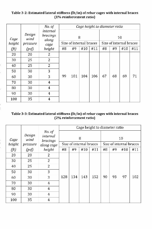
Table 3-2: Estimated lateral stiffness (Ib/in) of rebar cages with internal braces(1% reinforcement ratio)
Cageheight
(ft)20
30
40
50
60
70
80
90
100
Designwind
pressure
(PSf)
20
25
25
30
30
30
30
30
35
No. ofinternalbracings
alongcage
height
2
2
2
3
3
4
4
4
4
Cage height to diameter ratio
8
Size of internal braces#8
99
#9
101
#10
104
#11
106
10
Size of internal braces#8
67
#9
68
#10
69
#11
71
Table 3-3: Estimated lateral stiffness (Ib/in) of rebar cages with internal braces(2% reinforcement ratio)
Cageheight
(ft)20
30
40
50
60
70
80
90
100
Designwind
pressure
(Ptf20
25
25
30
30
30
30
30
35
No. ofinternalbracings
along cageheight
2
2
2
3
3
4
4
4
4
Cage height to diameter ratio
8
Size of internal braces#8
128
#9
134
#10
143
#11
152
10
Size of internal braces#8
90
#9
93
#10
97
#11
102
Dow
nloa
ded
from
asc
elib
rary
.org
by
Paul
Ow
ens
on 0
9/22
/15.
Cop
yrig
ht A
SCE
. For
per
sona
l use
onl
y; a
ll ri
ghts
res
erve
d.
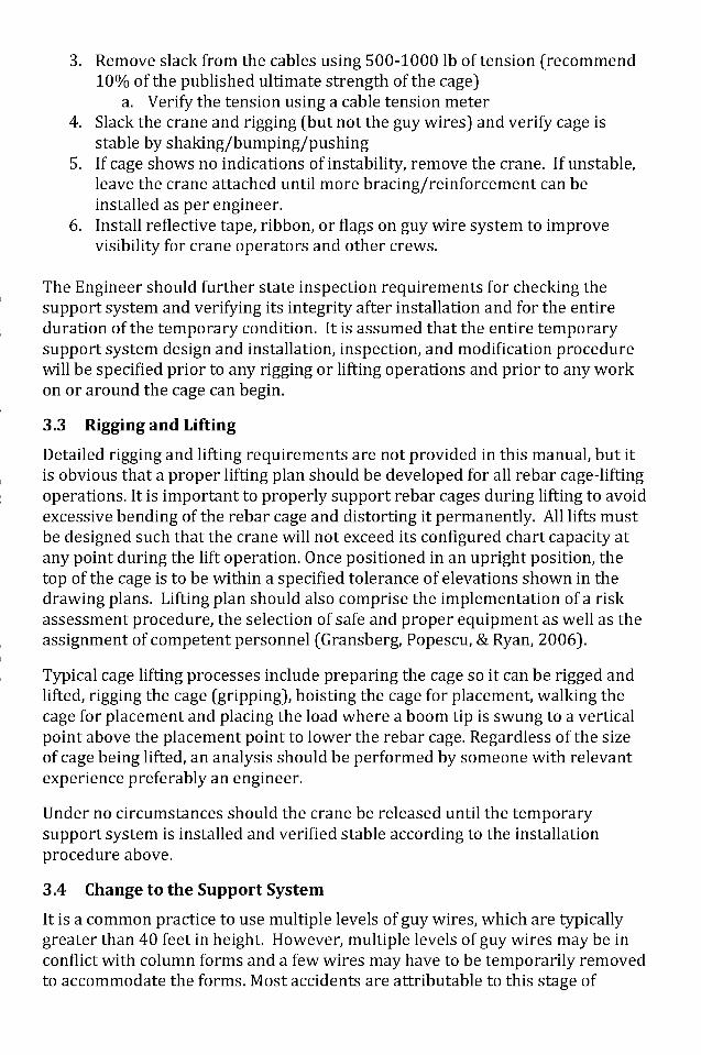
3. Remove slack from the cables using 500-1000 Ib of tension (recommend10% of the published ultimate strength of the cage)
a. Verify the tension using a cable tension meter4. Slack the crane and rigging (but not the guy wires) and verify cage is
stable by shaking/bumping/pushing5. If cage shows no indications of instability, remove the crane. If unstable,
leave the crane attached until more bracing/reinforcement can beinstalled as per engineer.
6. Install reflective tape, ribbon, or flags on guy wire system to improvevisibility for crane operators and other crews.
The Engineer should further state inspection requirements for checking thesupport system and verifying its integrity after installation and for the entireduration of the temporary condition. It is assumed that the entire temporarysupport system design and installation, inspection, and modification procedurewill be specified prior to any rigging or lifting operations and prior to any workon or around the cage can begin.
3.3 Rigging and Lifting
Detailed rigging and lifting requirements are not provided in this manual, but itis obvious that a proper lifting plan should be developed for all rebar cage-liftingoperations. It is important to properly support rebar cages during lifting to avoidexcessive bending of the rebar cage and distorting it permanently. All lifts mustbe designed such that the crane will not exceed its configured chart capacity atany point during the lift operation. Once positioned in an upright position, thetop of the cage is to be within a specified tolerance of elevations shown in thedrawing plans. Lifting plan should also comprise the implementation of a riskassessment procedure, the selection of safe and proper equipment as well as theassignment of competent personnel (Gransberg, Popescu, & Ryan, 2006).
Typical cage lifting processes include preparing the cage so it can be rigged andlifted, rigging the cage (gripping), hoisting the cage for placement, walking thecage for placement and placing the load where a boom tip is swung to a verticalpoint above the placement point to lower the rebar cage. Regardless of the sizeof cage being lifted, an analysis should be performed by someone with relevantexperience preferably an engineer.
Under no circumstances should the crane be released until the temporarysupport system is installed and verified stable according to the installationprocedure above.
3.4 Change to the Support System
It is a common practice to use multiple levels of guy wires, which are typicallygreater than 40 feet in height. However, multiple levels of guy wires may be inconflict with column forms and a few wires may have to be temporarily removedto accommodate the forms. Most accidents are attributable to this stage of
Dow
nloa
ded
from
asc
elib
rary
.org
by
Paul
Ow
ens
on 0
9/22
/15.
Cop
yrig
ht A
SCE
. For
per
sona
l use
onl
y; a
ll ri
ghts
res
erve
d.
construction (Builes-Mejia, Itani, & Sedarat, 2010). If such a constructionsequence is to be implemented, the stability of rebar cages during the partialremoval of some of the guy wires should be considered and the remaining guywires should be able to withstand the temporary loads for which the cage wasdesigned.
The stability of the rebar cage should also be checked before all temporarysupport system are released from cranes or lifting device. This will ensure thatthe temporary systems are secured and the rebar cage will not be inadvertentlydisplaced after release. It is recommended that cage deflection limits be set toensure stability of the cages before releasing cranes or lifting devices.
Formwork Procedure
1. Install the first level of formwork up to the first level of guy wire2. With Crane attached to the cage and rigging taught, move the guy wires,
one-at-a-time from the rebar cage to the form3. Re-tension guy wires4. Install formwork above guy wires
Dow
nloa
ded
from
asc
elib
rary
.org
by
Paul
Ow
ens
on 0
9/22
/15.
Cop
yrig
ht A
SCE
. For
per
sona
l use
onl
y; a
ll ri
ghts
res
erve
d.
Chapter 4Best Practices for Rebar Column Cage
Construction
The purpose of this Chapter is to outline our recommendations and guidelinesapplicable to field personnel based on the process and engineering backgroundpresented in the last two Chapters. The style is terse and direct based on theassumption that the reader is now familiar with information or is using thisChapter as a reference.
4.1 Checklists
The following sections present high-level check lists that should be useful forverifying each stage of the rebar cage design and construction process.
4.1.1 Permanent Design Checklist
• Have design alternatives been considered that allow for smaller columncages or allowances for segmental construction?
• Was additional longitudinal reinforcement or stronger ties considered topromote greater stiffness for the cage's temporary condition?
• Has the fabricator or rebar sub-contractor detailed internal braces and willthey provide sufficient stiffness?
• Was a constructability review done in consultation with the generalcontractor to identify potential conflicts with staging, lifting, or supporting ofthe cage on site?
4.1.2 Fabrication Checklist
These checks are adopted from Builes-Mejia et al. (2010).
For bridge column cages with diameters of 4 ft and larger:
• Tie wire connections shall use not smaller than 15 gauge tie wire made ofsoft annealed black steel with a minimum ultimate strength of 40 ksi.
• At least four vertical bars forming a square shall be tied at every intersectionwith at least a double tie wire connection. The strength of these connectionsshall be adequate for cage pick-up.
• At a maximum of 8 ft increments, template hoops shall be tied at everyintersection with at least a wrap and saddle tie wire connection.
• At least 20% of the remaining reinforcement intersections shall be tied withsingle tie wire connections. The connections shall be staggered fromadjacent connections.
Dow
nloa
ded
from
asc
elib
rary
.org
by
Paul
Ow
ens
on 0
9/22
/15.
Cop
yrig
ht A
SCE
. For
per
sona
l use
onl
y; a
ll ri
ghts
res
erve
d.
The fabricator has the biggest role to play in increasing the lateral stiffness of thecage by following the above recommendations. The goal is to preventcatastrophic bucking of the cage, and with sufficient internal bracing, proper ties,and sufficient pick-up and longitudinal bars, if a collapse occurs it will be gradualand will minimize risk to workers.
4.1.3 Pre-lift and Lift Checklist
The construction engineer working for the general contractor and thesuperintendent and foreman of the erection crew will perform the pre-lift andlift-checklist. The following checklist is recommended two weeks prior to a cagelift (adopted from Harris Salinas Rebar, Inc.):
1. Review access to the job site and column rigging area. Verify the bracingpattern for pipes (tremies) for pouring.
2. Discuss hoisting information (weights, heights and other dimensions)including allowable lengths for charging, if required.
3. Discuss crane (capacity, reach, and radius) with lifting crew, foreman, andsuperintendent.
4. Review and discuss hazards, (underground, overhead electrical lines,reach concerns.)
5. Have a copy of and review pre-planning column plan.6. Have there been any changes to the drawings on site since the initial
detailing plan was completed?7. What is being used to do the lifting? Crane? Forklift?8. What size of crane or forklift will be required?9. What access is available for crane or forklift? Is it adequate?10. Check weights of lifts; is it the same as your pre-plan procedure?11. What are your factors of safety to crane, rigging?12. What is the dowel pattern? Are the dowels the correct height? Are they in
the correct location?13. What rigging are you going to use? What rigging do you have?14. Check size of rigging. Do you require a strong back or spreader?15. What rigging blocks and/or special rigging are required? (Snatch blocks,
shackles)16. Do you need a rigging plan or is it a standard or typical lift for this
project?17. Have you inspected the rigging?18. If guying or bracing is required, do you have a written plan? Who is going
to supply?19. Who will be on the crew doing this work, what is their experience, have
they done this type of work before?20. Ask for different opinions on pick points.21. Do you have all the information needed or are you missing anything?22. Review your plan with another foreman or supervisor.23. Are there any flares to be built on the column, will they be done in the
yard or field?
Dow
nloa
ded
from
asc
elib
rary
.org
by
Paul
Ow
ens
on 0
9/22
/15.
Cop
yrig
ht A
SCE
. For
per
sona
l use
onl
y; a
ll ri
ghts
res
erve
d.
24. Obtain guying procedure from General Contractor or ConstructionEngineer, whichever applies.
25. Is the guying procedure appropriate for this column? Who is going tosupply and install?
26. Is it engineered and stamped?27. Carefully review guying procedure.28. Is there proper truck access?29. Is there room to off-load column from truck to ground?30. Are you lifting off the trailer?31. Do you need a crane with a main line and a whip line or 2 cranes?32. Is boom, main line, whip line & column going to line up when tripping
column?33. Have someone your level or higher to talk over the hoisting plan with.34. Compare each others plans.35. Get together to review each others plans.36. Look for the following: things that are the same, things that are different,
discuss the differences. Make drawings with the necessary changes.Agree on the best hoisting plan.
37. Start drawing the hoisting plan you agree on.38. On the drawing, provide the following information: length of column,
diameter of column, weight, unit weight of column per foot, layout of thepick points.
39. Start planning rigging; discuss the safety factors you want to use.40. Start with the strong back or spreader beam, shackles, skoocums' (snatch
blocks, shackles.)41. Running line, wire rope length sizes? Double check Jewell out. (i.e.,
rigging fits as it runs through skoocums or snatch block as column istripped. Check angle for right size)
42. Chokers nylons or wire rope (length and sizes.)43. Back up bars. What back up bars do you need?44. Check bracing within the column, is it sufficient?45. Is a Rat slab going to be needed for soil conditions?46. Does contractor need crane packs or metal plate for ground stabilization?47. Make sure picking bars are tied solid.48. Top few hoops above pick point should be tied solid.49. Will spreader bar fit onto hook of crane?50. Will running line rigging fit on hook?51. On single barrel columns added brace bars wrapped around the outside
of the column approximately 15 feet up to keep column from corkscrewing down (depending on size of verticals.)
The following checklist is recommended before the column erection work:
1. Have you completed a Job Hazard Analysis?2. Establish who will direct the crane operator; determine if hand signals or
radio will be used to communicate.
Dow
nloa
ded
from
asc
elib
rary
.org
by
Paul
Ow
ens
on 0
9/22
/15.
Cop
yrig
ht A
SCE
. For
per
sona
l use
onl
y; a
ll ri
ghts
res
erve
d.
3. Have all guy lines & braces (if required) been installed on column prior toerection? Ensure guy lines & braces are easily accessible without theneed to climb the column. Check cable clamps.
4. Notify contractor and other subs that all guying & bracing only to beremoved by Harris personnel. Have guying and or bracing check off sheeton site.
5. Foreman to inspect bracing and guy lines to ensue materials are good.6. Is fall protection required? If so, is there a procedure in place? Are there
other methods available (i.e. man baskets, genie lifts, scaffolding, etc?)7. Are there other trades working in the vicinity of the erection & if so,
ensure that adequate warning is given of the impending hazard. (Whenpicking column all personnel need to stay at least the length of thecolumn away, except for the signal person & persons on the tag lines.)Foreman to check each cable clamp.
8. Rig column as per Harris safe work procedure for your area(state/province) to ensure all hoisting rigging can be removed withoutthe need to climb the column. (Alternately, climb only after a foremanconfirms that all guying & bracing is complete and column is safe todisconnect rigging.)
9. Establish if tag lines need to be used and if so, that the person holdingthem has been properly trained. (Where to go in case of emergency.)
10. If column is going to be secured to formwork, ensure that the formworkhas been designed to support the additional weight of the cage. Inaddition, review formwork details to ensure that there are means of tyingoff the column.
11. Inspect the cage to be flown to ensure no loose verts or untied pieces;Ensure column is adequately tied to carry weight of other ties or verts.
12. Ensure no one stands below column as its being flown throughout the jobsite.
13. Make good all dowels in preparation of accepting column.14. Have a tail-gate meeting with the crew responsible for rigging, including
crane operator and contractor's rigger (if applicable) to review all actionsand hazards just prior to erection operation commences, include awritten sign off sheet.
15. Does everyone on the erection crew agree with the plan? If yes - proceed,If NO - resolve the differences before beginning work.
16. Install all chairs or spacers on the column prior to erection to prevent theneed to climb the column or formwork after the column is erected.(Alternately, climb only after a foreman confirms that all guying & bracingis complete and column is safe to disconnect rigging.)
17. All guying & bracing to be adequately identified with reflective tape orflags at appropriate heights to make highly visible to crane operators,mobile equipment operators and personnel.
18. Tie all the right angles on the bottom of footing solid.
Dow
nloa
ded
from
asc
elib
rary
.org
by
Paul
Ow
ens
on 0
9/22
/15.
Cop
yrig
ht A
SCE
. For
per
sona
l use
onl
y; a
ll ri
ghts
res
erve
d.
Finally, the on the day of the erection work, the following summary checklist isrecommended:
• Know the set up of the cranes• Know the effect the hoist has on the crane• Know where to look when hoisting, watch for the unknown - all eyes
should be watching.• Watch for side loading• Watch for non-plumb vertical lines.• Watch for line and sheave problems.• Watch and understand boom deflections• Watch for column trip problems.• Special rigging training by a wire rope manufacturer, 3 classes on jobsite
training required.• On heavy picks a person should be watching the back side of the crane to
make sure its not raising up.• If we are using the contractor's spreader bar, make sure it is certified
before using.
4.1.4 Temporary Condition Checklist
The cage should be released from its guy wires: 1) only when necessary for theplacement/movement of formwork, 2) in symmetrical pairs only to keep thecage in static equilibrium, 3) for a minimum amount of time only and with extracare for knocking or bumping an unsupported cage.
Additional recommendations are adopted from Harris-Salinas Rebar, Inc.:
1. Tie off bottom of cage to dowel rebar as determined during pre-planning.Alternately, are bottom of column right angles secured to bottom mat orsupport frame as determined during pre-planning?
2. Ensure column is not released from crane until all bracing and /or guylines (if applicable) are installed. Foreman to inspect columns and/orbracing or guying and complete a check list for all columns set in a dayand record on sign off sheet. Turn in copy of check off to generalcontractor if required.
3. Instruct General Contractor and other trades not to touch bracing and/orguy lines.
4. Foreman to check cable clamps or braces.
Dow
nloa
ded
from
asc
elib
rary
.org
by
Paul
Ow
ens
on 0
9/22
/15.
Cop
yrig
ht A
SCE
. For
per
sona
l use
onl
y; a
ll ri
ghts
res
erve
d.
4.1.5 Permanent Condition Checklist
The permanent condition is achieved when all concrete is poured andsufficiently cured and all formwork is removed from the column. The followingrecommendations are made about the permanent condition:
• Have the guys or temporary supports been moved or removed in amanner inconsistent with the temporary support plan? If so, document.
• Has all rigging and support hardware been removed and inspected fordamage?
• Have the support systems of adjacent or nearby cages been affected bythe removal of this columns supports?
4.2 Summary
These checklists are intended to provide informed guidance at each stage of theproposed standard rebar design and construction process.
Dow
nloa
ded
from
asc
elib
rary
.org
by
Paul
Ow
ens
on 0
9/22
/15.
Cop
yrig
ht A
SCE
. For
per
sona
l use
onl
y; a
ll ri
ghts
res
erve
d.
Chapter 5Summary, Conclusions, and
Recommendations for Future Work
5.1 Summary
The placement of rebar cages for large, cast in place concrete columns hasbecome a common operation in heavy civil construction. Tall bridge piers orhighway fly-overs are some examples that require these large concrete columns.This manual has assembled best practices related to construction engineeringand to construction practice for handling cages. The best practices are intendedas guide for those organizations who lack standard procedures for handlingrebar cages to adopt their own.
The major recommendations are summarized in the Preface of this manual, butthe following are the most crucial ones that, if nothing else, should be adopted:
• Any cage with a H/D ratio greater than 8 needs to be supported, as does anycage that requires an iron worker to climb on it.
• A registered Professional Engineer should select, design, and inspect atemporary support system used for rebar column cages. Any changes ordeviations from the support plan should be reviewed and approved by theconstruction engineer.
• Internal bracing supplied by the fabricator or rebar contractor should beincluded. Square-type braces can be used to allow for placement of tremietubes or conduits and negative impacts to seismic response can be accountedfor in the design process.
• During lifting/tripping, cages should not be released from a crane until thesupport system is completely in place and verified stable.
• For cages over 20' - the suggested method of upending (tripping) would beto rig the cage in multiple locations (top - head, bottom and potentially themid-point(s) depending on length). This can be accomplished many ways,not limited to: using a single crane with a rolling block, using a single cranewith multiple load lines or with two cranes. Whichever method is utilized, itmust be analyzed to not overload the crane or load line with the leastcapacity.
• Upending (tripping) of cages over 20' should be reviewed and analyzed by anindividual with experience in lifting large rebar cages.
5.2 Conclusions
The following conclusions can be made:
Dow
nloa
ded
from
asc
elib
rary
.org
by
Paul
Ow
ens
on 0
9/22
/15.
Cop
yrig
ht A
SCE
. For
per
sona
l use
onl
y; a
ll ri
ghts
res
erve
d.
• Some of the most experienced contractors with the best safety records haveno formal policies for handing temporary works at all. Their engineering andconstruction practice is based on experience, "the way they have always doneit", and it works. One main goal of this manual is to aid organizations orindividuals, e.g., junior construction engineers, who may lack this experience.
• The largest cages are not usually the cause of accidents because they tend toreceive a lot of engineering scrutiny and oversight. Cages as small as 20ft tallhave collapsed and have led to fatalities. Any cage requiring an iron workerto climb on it must be supported.
• Change to the engineered support system (i.e., the removal or movement ofguy wires) is the number one cause of accidents involving guy wires.Construction engineers must specify not just the system itself, but itsremoval sequence.
• A responsibility matrix is a useful tool for defining the roles andresponsibilities necessary for the safe handing of rebar cages. However, thematrix is not static. It must be binding and updated throughout the process.Contractors have to use it as an instrument that is capable of stopping workcompletely when it is dangerous or unknown conditions warrant it.
5.3 Recommendations for Future Work
The problem of safety with the handing of rebar cages is a broad one andencompasses the interest of a wide array of stakeholders including large owners,general contractors, fabricators, rebar sub-contractors, and iron workers.Unfortunately, this Manual could not address all issues for all constituencies, butis focused primarily on the temporary support of rebar column cages standingabove grade.
We recommend that additional research be performed that broadens the scopeof this Manual, perhaps with the co-sponsorship of other professionalorganizations such as CRSI or DPI (Deep Foundations Institute). Collaborationwith a larger group or stakeholders has the potential to broaden the impact ofthis research and to promote wider adoption of the best practices presented inthis Manual.
More research-specific recommendations are related to an investigation of windpressure reductions and adequacy of drilled shaft reinforcement. For theformer, amongst construction engineers working in this area, it is believed thattemporary support systems such as guy-wire/anchor systems are generallyover-designed because of conservative estimates of lateral wind loads incidenton vertical cages. The spaces between rebar permit wind-pass through such thatwind reduction factors might be applied in determining lateral loads. It isestimated that such reduction factors could reduce the anchor block sizerequirements and guy-wire size/tension by up to 25%. Further research isneeded, perhaps experimental programs involving wind-tunnel type studies, totest these claims and affect construction engineering practice in this area.
Dow
nloa
ded
from
asc
elib
rary
.org
by
Paul
Ow
ens
on 0
9/22
/15.
Cop
yrig
ht A
SCE
. For
per
sona
l use
onl
y; a
ll ri
ghts
res
erve
d.
In considering rebar cages for deep foundations, it is similarly believed amongstpractitioners that these cages are possibly over-designed. Rebar hoops, whichnormally provide confinement for concrete to resist blow-out during bendingaction, should be less important for cages used for CIDH piles as the piles areconfined by the shafts themselves. Smaller, lighter cages to be placed in deepshafts would be easier to handle and arguably safer during the tripping andlifting process. Further research, perhaps in partnership with DPI andgeotechnical experts is warranted.
The most challenging aspect in designing temporary support systems for rebarcages is the lack of rigidity of the cage itself. Large cages are analogous to "wetpasta noodles" and present problems during tripping/lifting and the temporarycondition. While shop or field tying with tie wire has been the industry standardpractice for decades, research is alternative fabrication techniques that cangreatly improve cage stability without impacting seismic, i.e. plastic-hinge,behavior are needed. Limited spot-welding and semi-automated fabrication mayaddress this issue in the future.
Dow
nloa
ded
from
asc
elib
rary
.org
by
Paul
Ow
ens
on 0
9/22
/15.
Cop
yrig
ht A
SCE
. For
per
sona
l use
onl
y; a
ll ri
ghts
res
erve
d.
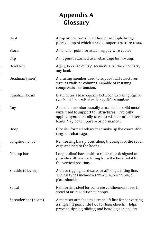
Appendix AGlossary
Bent
Block
Clip
Dead Guy
Deadman (men)
Equalizer beam
Guy
Hoop
Longitudinal bar
Pick-up bar
Shackle (devise)
Spiral
Spreader bar (beam)
A cap or horizontal member for multiple bridgepiers on top of which a bridge super structure rests.
An anchor point for attaching guy wire cables
A lift point attached to a rebar cage for hosting.
A guy, because of its placement, that does not carryany load.
A bracing member used to support tall structuressuch as walls or columns. Capable of resistingcompression or tension.
Distributes a load equally between two sling legs ortwo hoist lines when making a lift in tandem.
A tension member, usually a braided or solid metalwire, used to support tall structures. Typicallyapplied symmetrically to resist wind or other lateralloads. May be temporary or permanent.
Circular-formed rebars that make up the concentricrings of rebar cages.
Reinforcing bars placed along the length of the rebarcage and tied to the hoops.
Longitudinal bars inside a rebar cage designed toprovide stiffness for lifting from the horizontal tothe vertical position.
A piece rigging hardware for affixing a lifting line.Typical types include a screw pin, round pin, orplate shackle.
Reinforcing steel for concrete confinement used instead of or in addition to hoops.
A member attached to a crane lift line for convertinga single lift point into two for long objects. Helpsprevent, tipping, sliding, and bending during lifts.
Dow
nloa
ded
from
asc
elib
rary
.org
by
Paul
Ow
ens
on 0
9/22
/15.
Cop
yrig
ht A
SCE
. For
per
sona
l use
onl
y; a
ll ri
ghts
res
erve
d.
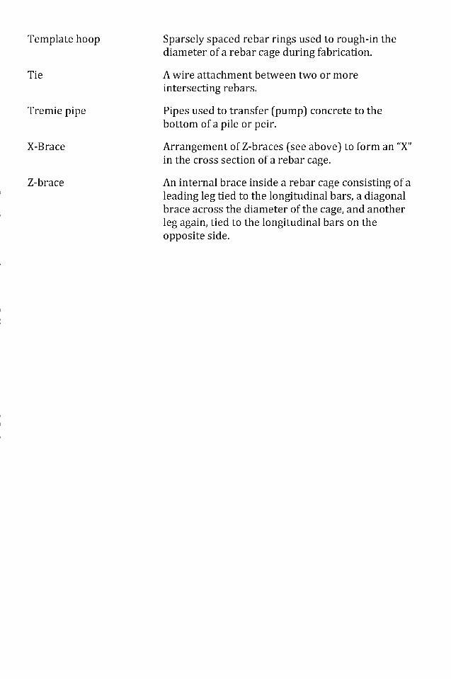
Template hoop Sparsely spaced rebar rings used to rough-in thediameter of a rebar cage during fabrication.
Tie A wire attachment between two or moreintersecting rebars.
Tremie pipe Pipes used to transfer (pump) concrete to thebottom of a pile or peir.
X-Brace Arrangement of Z-braces (see above) to form an "X"in the cross section of a rebar cage.
Z-brace An internal brace inside a rebar cage consisting of aleading leg tied to the longitudinal bars, a diagonalbrace across the diameter of the cage, and anotherleg again, tied to the longitudinal bars on theopposite side.
Dow
nloa
ded
from
asc
elib
rary
.org
by
Paul
Ow
ens
on 0
9/22
/15.
Cop
yrig
ht A
SCE
. For
per
sona
l use
onl
y; a
ll ri
ghts
res
erve
d.
References
ASCE. (2002). Design Loads on Structures During Construction ( No. ASCE 37-02).Reston, VA: American Society of Civil Engineers.
Billodeau, C. (2010). Practice Bulletin for upending rebar cages and/or peircolumns. Brayman Construction.
Builes-Mejia, J. C., Itani, A., & Sedarat, H. (2010). Stability of Bridge Column RebarCages during Construction ( No. CCEER 10-07). Reno, NV: University ofNevada, Reno.
Caltrans. (2006). Standard Specifications (p. 872). Sacramento, CA: CaliforniaDepartment of Transportation.
Chen, W. F., & Duan, L. (2003). Bridge Engineering: Construction and Maintenance(First Edition.). CRC Press.
CRSI. (2005). Placing Reinforcing Bars.
Fisk, E., & Reynolds, W. (2010). Construction Project Administration (NinthEdition.). Pearson.
Gantes, C., Khoury, R., Connor, J. J., & Pouangare, C. (1993). Modeling, loading,and preliminary design considerations for tall guyed towers. Computers &Structures, 49(5), 797-805.
Goldbloom, J. (1975). Recommended Standards for the Responsibility, Authority,and Behavior of the Inspector. Journal of the Construction Division,101(CQ2), 360-363.
Gransberg, D., Popescu, C., & Ryan, R. (2006). Construction EquipmentManagement for Engineers, Estimators, and Owners. CRC Press.
KDOT. (2009). Bridge Construction Manual: Chapter 5: Drilled Shafts (p. 38).Topeka, KS: Kansas Department of Transportation.
VDOT. (2011). Manual of the Structure and Bridge Division, Volume V - Part 2.Design Aids - Typical Details. Virginia Department of Transportation.
Dow
nloa
ded
from
asc
elib
rary
.org
by
Paul
Ow
ens
on 0
9/22
/15.
Cop
yrig
ht A
SCE
. For
per
sona
l use
onl
y; a
ll ri
ghts
res
erve
d.
Index
Page numbers followed by/and t indicate figures and tables, respectively.
AISC Steel Construction Manual 21anchor blocks, in temporary support
systems 18, 18/j design of 22-23
ASCE Policy 424 11ASCE Standard 37-02 16-17
best practices 4best practices checklists: fabrication
27-28; permanent condition 32;permanent design 27; pre-liftand lift 28-31; temporarycondition 31
bracing, in temporary supportsystems 21
California 1, 8CalTrans 6, 8, 17change: guy wires and 25-26;
organizational management and15
"clotheslining" 18-19communication, need for 14-15Concrete Reinforcing Steel Institute
(CRSI) 2construction (live) loads 17construction engineering 16-26;
change to support system 25-26; recommendations vi; riggingand lifting 25; temporarysupport systems 16-19, 17t, 18/20/21-23, 24t, 25
contractor size, policies and 8
dead loads 16design and construction process 8-
12; fabrication 9f, 10-11;geographic variations 8; liftoperations 9f, 11; permanent
construction 9f, 12; pre-liftoperations 9f, 11; structural(permanent) design 9-10, 9/jtemporary condition 9f, 12, 21
Design-Build/Design-Bid-Buildprojects 8
environmental loads 17, 17terection and fitting forces 17
fabrication 1; best practiceschecklist 27-28; in design andconstruction process 9f, 10-11;responsibility matrix 14/
Fisk, E. 12
guy wires: changes to supportsystem and 25-26; installationprocedure 23, 25; in temporarysupport systems 18, 19, 20/ 21-22
Harris-Salinas Rebar, Inc. 31horizontal supports, in temporary
systems 18-19
inspection, for fabricationverification 10-11
inspector, organizationalmanagement and 12-13
installation, of temporary supportsystem 23, 25
internal bracing, design of 23, 24tinternal support systems 19, 20/
lift operations: best practiceschecklist 28-31; characteristicsof well-planned and well-executed 2, 2/; in design and
Dow
nloa
ded
from
asc
elib
rary
.org
by
Paul
Ow
ens
on 0
9/22
/15.
Cop
yrig
ht A
SCE
. For
per
sona
l use
onl
y; a
ll ri
ghts
res
erve
d.
construction process 9f, 11;responsibility matrix 14/; typicalprocesses 25
load determination, for temporarysupport systems 16-17, 17t
mechanically spliced baseconnections 19
on- and offsite fabrication 10organizational management 8-15;
change management and 15;communication needs 14-15;design and construction process8-12, 9/; responsibility matrix13-14, 14/j roles andresponsibilities 12-13
permanent condition: best practiceschecklist 32; in design andconstruction process 9f, 12;responsibility matrix 14/
permanent design, best practiceschecklist 27
pinned connections, in temporarysupport systems 19
pole braces, in temporary supportsystems 18, 18/
pre-lift operations: best practiceschecklist 28-31; in design andconstruction process 9f, 11;responsibility matrix 14/
rebar cages, for cast-in-placestructures: accidents and v, 1;anatomy of 2-3, 3/;characteristics of well-designed1-2; size and weight of v-vi
recommendations and conclusions:conclusions 33-34; constructionengineering recommendationsvi; construction practicerecommendations vi-vii; futureresearch recommendations 34-35; major recommendations 33
resistance forces, determining intemporary support systems 19, 2 1
Reynolds, W. 12rigging, organizational management
and 25roles and responsibilities:
organizational management and12-13; responsibility matrix 13-14, 14/
square braces 23structural (permanent) design,
organizational management and9-10, 9/
structural analysis, in temporarysupport systems 19,21
temporary support systems 16; bestpractices checklist 31; in designand construction process 9f, 11,12; design of system 21-23, 24t;installation of 23, 25; loaddetermination 16-17, 17t;responsibility matrix 14/;selection of system 17-19, 18/20/j structural analysis 19, 21
turnkey subcontractors 8,10
wind pressure resistance 17, 17t
X-braces 23
Dow
nloa
ded
from
asc
elib
rary
.org
by
Paul
Ow
ens
on 0
9/22
/15.
Cop
yrig
ht A
SCE
. For
per
sona
l use
onl
y; a
ll ri
ghts
res
erve
d.