Embed Size (px)
Citation preview
RECENT ADVANCEMENTS IN THE APPLICATION OF EMATS TO NDE D. MacLauchlan, S. Clark, B. Cox, T. Doyle, B. Grimmett, J. Hancock, K. Hour, C. Rutherford
BWXT Services, Non Destructive Evaluation and Inspection Systems, Lynchburg, Virginia, USA Abstract: Electromagnetic Acoustic Transducers (EMATS) are emerging as a mainstream Non-Destructive Evaluation (NDE) technique. EMATs offer several distinct advantages over traditional piezoelectric transducers for many inspection applications requiring novel solutions. These advantages include: operation without a coupling fluid, non-contact operation, high temperature operation, and the ability to utilize shear horizontal (SH) waves. EMATs are also ideally suited to launching and receiving Raleigh waves, Lamb waves, and shear horizontal (SH) plate waves. The primary disadvantage of EMATs when compared to piezoelectric transducers is poor transduction efficiency. Until recently, this disadvantage has limited the application of EMATs for ultrasonic inspections. Recent advancements in EMAT technology has resulted in dramatic improvements in EMAT operation. Significant advancements in computer simulation, magnet materials, analog electronics, phased array electronics, digital signal processing, and digital computational power have resulted in substantial improvements in the performance of EMATs for a wide variety of applications. Three-dimensional electromagnetic and ultrasonic modeling of EMATs allows rapid optimization of transducer design. Improvements in the strength of magnetic fields available with permanent magnets have produced substantial improvements in EMAT sensitivity. Further advancements in analog electronics have resulted in compact high peak-power pulsers and low noise receivers to largely overcome the lower transduction efficiency of EMATs. The coupling of EMATs with the recently introduced phased array instruments for NDT has resulted in dramatic improvements in the performance and range of applications. Hardware based digital signal processing can also be employed to provide real time additional performance improvements for EMAT applications. The net effect of all these technological advancements is that EMATs are becoming a recognized technology for addressing a wide variety of NDE applications. Introduction: Electromagnetic Acoustic Transducers (EMATS) are emerging as a mainstream Non-Destructive Evaluation (NDE) technique. Today, EMATs are in commercial use for a number of different applications. EMATs offer several distinct advantages over traditional piezoelectric transducers for many inspection applications requiring novel solutions. These advantages include: operation without a coupling fluid, non-contact operation, high temperature operation, and the ability to utilize shear horizontal (SH) waves. EMATs are also ideally suited to launching and receiving Raleigh waves, Lamb waves, and shear horizontal (SH) plate waves. The primary disadvantage of EMATs when compared to piezoelectric transducers is poor transduction efficiency. For bulk wave Lorentz force EMATs operating such that the ultrasound wavelength is much longer than the electromagnetic skin depth and ignoring diffraction losses, an estimation of the received voltage across the terminals of the EMAT coil is given by:
VEMAT = IEMATN2B2AExp(-αG/D)/(ZL,S) 1
Where: VEMAT is the received voltage across the terminals of the EMAT coil, IEMAT is the current pulse used to drive the EMAT coil, N is the number of turns per unit length for the EMAT coil, B is the static magnetic field, A is the active area of the EMAT, G is the effective gap between the EMAT coil and the surface of the part, D is the diameter of the coil, and α is a geometry dependent constant. ZL,S is the acoustic impedance of the part, either longitudinal or shear. Assuming a noiseless amplifier and ideal matching, the received noise level (referred to the input) is given by:
Vnoise = (4KTβREMAT)1/2 2
Where: K is Boltzman’s constant times e the electronic charge (MKS units), T is temperature in degrees Kelvin, β is the bandwidth of the amplifier in Hertz, REMAT is the resistance of the EMAT coil. The resistance of an EMAT coil subdivided into N turns can be shown to be:
REMAT = R0 (NW)2
Where: R0 is the resistance of a single turn coil of the same geometry as the EMAT coil and W is the width of width of the coil such that NW gives the total number of turns in the coil. The current used to drive the EMAT in transmission is related to the power by:
P0 = IEMAT2REMAT
A first order approximation for the received signal to noise can be obtained by combining these equations:
VEMAT/ Vnoise = (P0)1/2 B2AExp(-αG/D)/ (W2ZL,S (4KTβ) 1/2 R0)
Although there are many assumptions in deriving this expression it is useful to examine each of the terms in regards to optimizing the EMAT received signal to noise ratio. Maximizing the peak power delivered to the EMAT coil maximizes the received signal to noise ratio. Today, inexpensive, high pulse power transistors are available allowing 10 kW and higher tone burst pulses to be applied to the EMAT coil if desired. These transistors have simplified drive requirements and are capable of operating in excess of 10 MHz, making 20 MHz operation of bulk wave EMATs practical. Ultimately, the peak power that can be applied to the EMAT coil is limited by average power dissipation in the coil for repetitive pulsing. Methods to cool the coil can be employed allowing additional peak power or increased repetition rates to be used. Integrated circuit preamplifiers have also become available that offer wide bandwidth and very low noise. Typically, with these preamplifiers the majority of the random noise at the output is the amplified Johnson noise of the EMAT coils resistance. These preamplifiers typically contribute less than 10% of the total noise at the output, approaching the ideal noiseless amplifier. For bulk wave EMATs the reduction in sensitivity with increasing distance between the EMAT and the part surface is scaled by the diameter of the coil (or wire to wire spacing for meander coils). Using a larger diameter coil reduces the sensitivity to lift-off. However, the beam properties of the transducer are also related to the coil diameter so that in practice there is often little that can be done to reduce the lift-off sensitivity. Maintaining the coil as close to the part as possible minimizes the losses due to lift-off. The signal to noise ratio is inversely proportional to the square root of the bandwidth (β). By employing optimized bandwidth and roll off characteristics, further improvement in the received signal to noise ratio can be obtained. In some cases digital signal processing can be employed to provide this filtering, allowing the ultimate in versatile filtering. Digital signal averaging can also be employed to increase the signal to noise ratio. For random noise, the signal to noise ratio is improved by the square root of the number of waveforms averaged together. Since the received signal to noise ratio is proportional to the square of the static magnetic field, it is especially beneficial to maximize B. A large improvement in permanent magnet’s field strength was provided with the introduction of neodymium boron iron magnets. The field strength provided by these magnets continues to improve with the introduction of ever-improved magnetic materials. With the availability of finite element electromagnetic modeling tools, it has become practical to optimize the design of the magnets used to generate the magnetic field for
EMATs. In Figure 1 the graphical results of a 3D FEM magnetic field simulation is shown for a magnet assembly consisting of two cube permanent magnets on a mild steel yoke.
Figure 1 - Magnetic Field Simulation Results Example
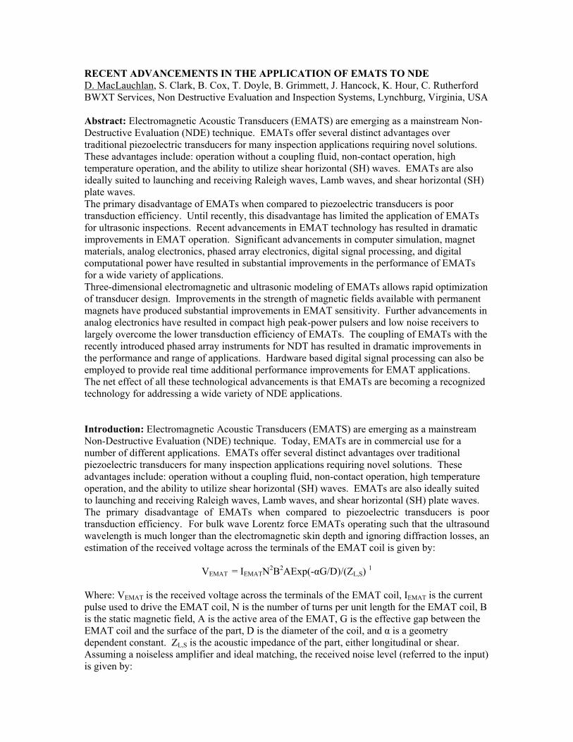
The EMAT signal to noise ratio is shown as being inversely proportional to R0, the resistance of a single turn coil of the same geometry as the actual EMAT coil. Clearly, the EMAT coil should be constructed from low resistivity material. Copper is normally used providing low resistivity at reasonable cost. The geometry of the coil can also be optimized to minimize the resistance. However, this is an oversimplification of the coil design process. Since EMATs generate ultrasound in the surface of the part itself, the majority of EMAT transducers are application specific. The ability to rapidly design and optimize an EMAT for a particular application is of benefit. Optimizing the EMAT coil can also be aided by the use of the FEM electromagnetic modeling tools. By calculating the static magnetic fields and the eddy current distribution in the part, the Lorentz forces generated in the surface of the part can be calculated. From these forces the propagating ultrasonic waves can be modelled. This modelling can be very useful for optimizing and verifying the design of the EMAT prior to fabrication. In Figure 2 the results of FEM modeling of the eddy current distribution in the surface of a metal block is shown for a variable spacing meander EMAT coil at a fixed distance above the metal.
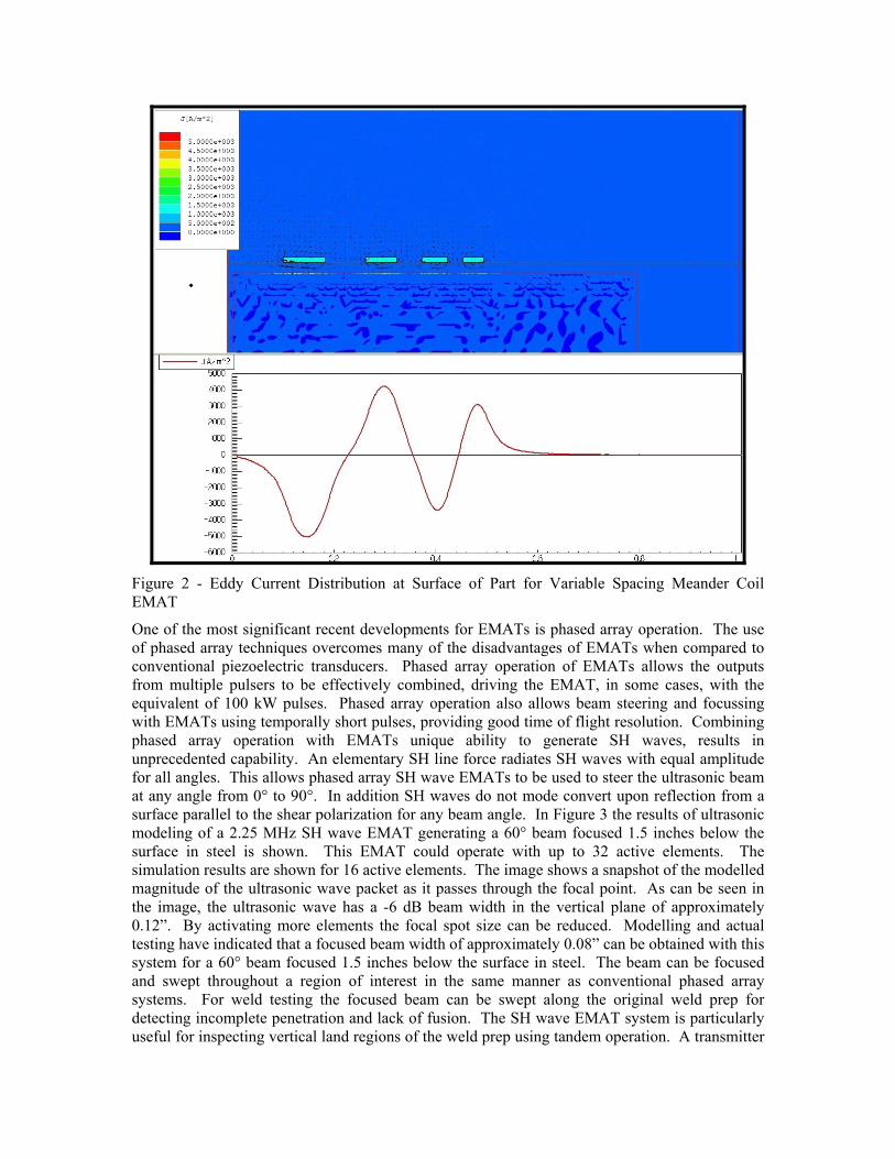
Figure 2 - Eddy Current Distribution at Surface of Part for Variable Spacing Meander Coil EMAT
One of the most significant recent developments for EMATs is phased array operation. The use of phased array techniques overcomes many of the disadvantages of EMATs when compared to conventional piezoelectric transducers. Phased array operation of EMATs allows the outputs from multiple pulsers to be effectively combined, driving the EMAT, in some cases, with the equivalent of 100 kW pulses. Phased array operation also allows beam steering and focussing with EMATs using temporally short pulses, providing good time of flight resolution. Combining phased array operation with EMATs unique ability to generate SH waves, results in unprecedented capability. An elementary SH line force radiates SH waves with equal amplitude for all angles. This allows phased array SH wave EMATs to be used to steer the ultrasonic beam at any angle from 0° to 90°. In addition SH waves do not mode convert upon reflection from a surface parallel to the shear polarization for any beam angle. In Figure 3 the results of ultrasonic modeling of a 2.25 MHz SH wave EMAT generating a 60° beam focused 1.5 inches below the surface in steel is shown. This EMAT could operate with up to 32 active elements. The simulation results are shown for 16 active elements. The image shows a snapshot of the modelled magnitude of the ultrasonic wave packet as it passes through the focal point. As can be seen in the image, the ultrasonic wave has a -6 dB beam width in the vertical plane of approximately 0.12”. By activating more elements the focal spot size can be reduced. Modelling and actual testing have indicated that a focused beam width of approximately 0.08” can be obtained with this system for a 60° beam focused 1.5 inches below the surface in steel. The beam can be focused and swept throughout a region of interest in the same manner as conventional phased array systems. For weld testing the focused beam can be swept along the original weld prep for detecting incomplete penetration and lack of fusion. The SH wave EMAT system is particularly useful for inspecting vertical land regions of the weld prep using tandem operation. A transmitter
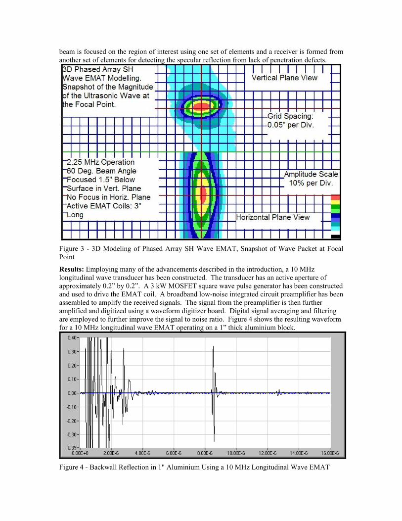
beam is focused on the region of interest using one set of elements and a receiver is formed from another set of elements for detecting the specular reflection from lack of penetration defects.
Figure 3 - 3D Modeling of Phased Array SH Wave EMAT, Snapshot of Wave Packet at Focal Point
Results: Employing many of the advancements described in the introduction, a 10 MHz longitudinal wave transducer has been constructed. The transducer has an active aperture of approximately 0.2” by 0.2”. A 3 kW MOSFET square wave pulse generator has been constructed and used to drive the EMAT coil. A broadband low-noise integrated circuit preamplifier has been assembled to amplify the received signals. The signal from the preamplifier is then further amplified and digitized using a waveform digitizer board. Digital signal averaging and filtering are employed to further improve the signal to noise ratio. Figure 4 shows the resulting waveform for a 10 MHz longitudinal wave EMAT operating on a 1” thick aluminium block.
Figure 4 - Backwall Reflection in 1" Aluminium Using a 10 MHz Longitudinal Wave EMAT
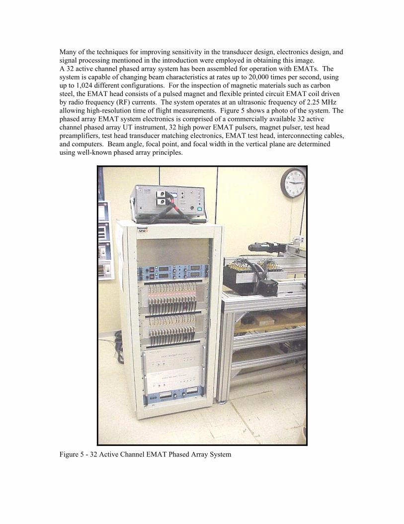
Many of the techniques for improving sensitivity in the transducer design, electronics design, and signal processing mentioned in the introduction were employed in obtaining this image. A 32 active channel phased array system has been assembled for operation with EMATs. The system is capable of changing beam characteristics at rates up to 20,000 times per second, using up to 1,024 different configurations. For the inspection of magnetic materials such as carbon steel, the EMAT head consists of a pulsed magnet and flexible printed circuit EMAT coil driven by radio frequency (RF) currents. The system operates at an ultrasonic frequency of 2.25 MHz allowing high-resolution time of flight measurements. Figure 5 shows a photo of the system. The phased array EMAT system electronics is comprised of a commercially available 32 active channel phased array UT instrument, 32 high power EMAT pulsers, magnet pulser, test head preamplifiers, test head transducer matching electronics, EMAT test head, interconnecting cables, and computers. Beam angle, focal point, and focal width in the vertical plane are determined using well-known phased array principles.
Figure 5 - 32 Active Channel EMAT Phased Array System
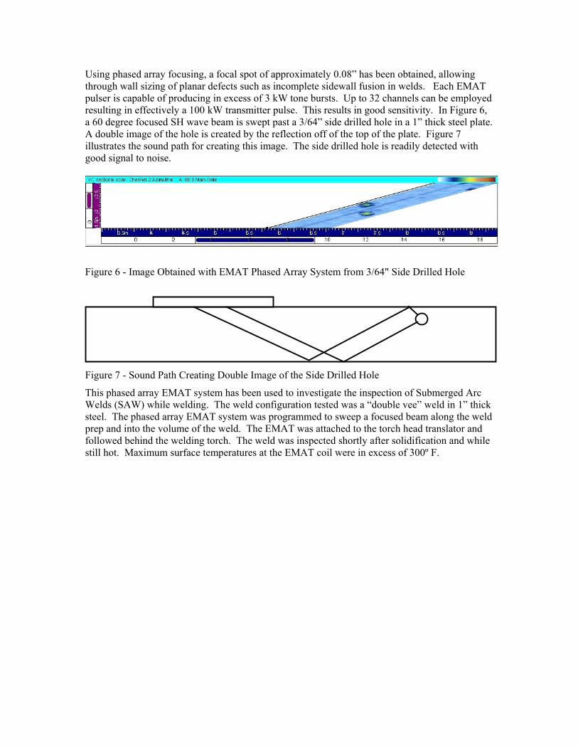
Using phased array focusing, a focal spot of approximately 0.08” has been obtained, allowing through wall sizing of planar defects such as incomplete sidewall fusion in welds. Each EMAT pulser is capable of producing in excess of 3 kW tone bursts. Up to 32 channels can be employed resulting in effectively a 100 kW transmitter pulse. This results in good sensitivity. In Figure 6, a 60 degree focused SH wave beam is swept past a 3/64” side drilled hole in a 1” thick steel plate. A double image of the hole is created by the reflection off of the top of the plate. Figure 7 illustrates the sound path for creating this image. The side drilled hole is readily detected with good signal to noise.
Figure 6 - Image Obtained with EMAT Phased Array System from 3/64" Side Drilled Hole
Figure 7 - Sound Path Creating Double Image of the Side Drilled Hole
This phased array EMAT system has been used to investigate the inspection of Submerged Arc Welds (SAW) while welding. The weld configuration tested was a “double vee” weld in 1” thick steel. The phased array EMAT system was programmed to sweep a focused beam along the weld prep and into the volume of the weld. The EMAT was attached to the torch head translator and followed behind the welding torch. The weld was inspected shortly after solidification and while still hot. Maximum surface temperatures at the EMAT coil were in excess of 300º F.
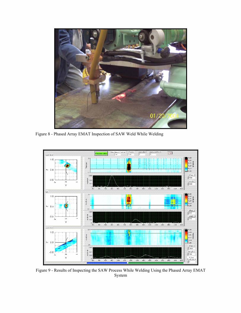
Figure 8 - Phased Array EMAT Inspection of SAW Weld While Welding
Figure 9 - Results of Inspecting the SAW Process While Welding Using the Phased Array EMAT
System
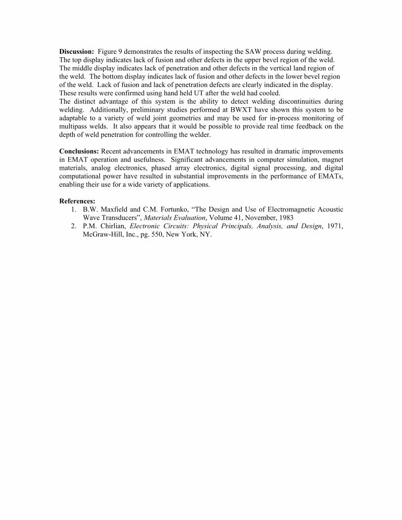
Discussion: Figure 9 demonstrates the results of inspecting the SAW process during welding. The top display indicates lack of fusion and other defects in the upper bevel region of the weld. The middle display indicates lack of penetration and other defects in the vertical land region of the weld. The bottom display indicates lack of fusion and other defects in the lower bevel region of the weld. Lack of fusion and lack of penetration defects are clearly indicated in the display. These results were confirmed using hand held UT after the weld had cooled. The distinct advantage of this system is the ability to detect welding discontinuities during welding. Additionally, preliminary studies performed at BWXT have shown this system to be adaptable to a variety of weld joint geometries and may be used for in-process monitoring of multipass welds. It also appears that it would be possible to provide real time feedback on the depth of weld penetration for controlling the welder. Conclusions: Recent advancements in EMAT technology has resulted in dramatic improvements in EMAT operation and usefulness. Significant advancements in computer simulation, magnet materials, analog electronics, phased array electronics, digital signal processing, and digital computational power have resulted in substantial improvements in the performance of EMATs, enabling their use for a wide variety of applications. References:
1. B.W. Maxfield and C.M. Fortunko, “The Design and Use of Electromagnetic Acoustic Wave Transducers”, Materials Evaluation, Volume 41, November, 1983
2. P.M. Chirlian, Electronic Circuits: Physical Principals, Analysis, and Design, 1971, McGraw-Hill, Inc., pg. 550, New York, NY.