Embed Size (px)
Citation preview
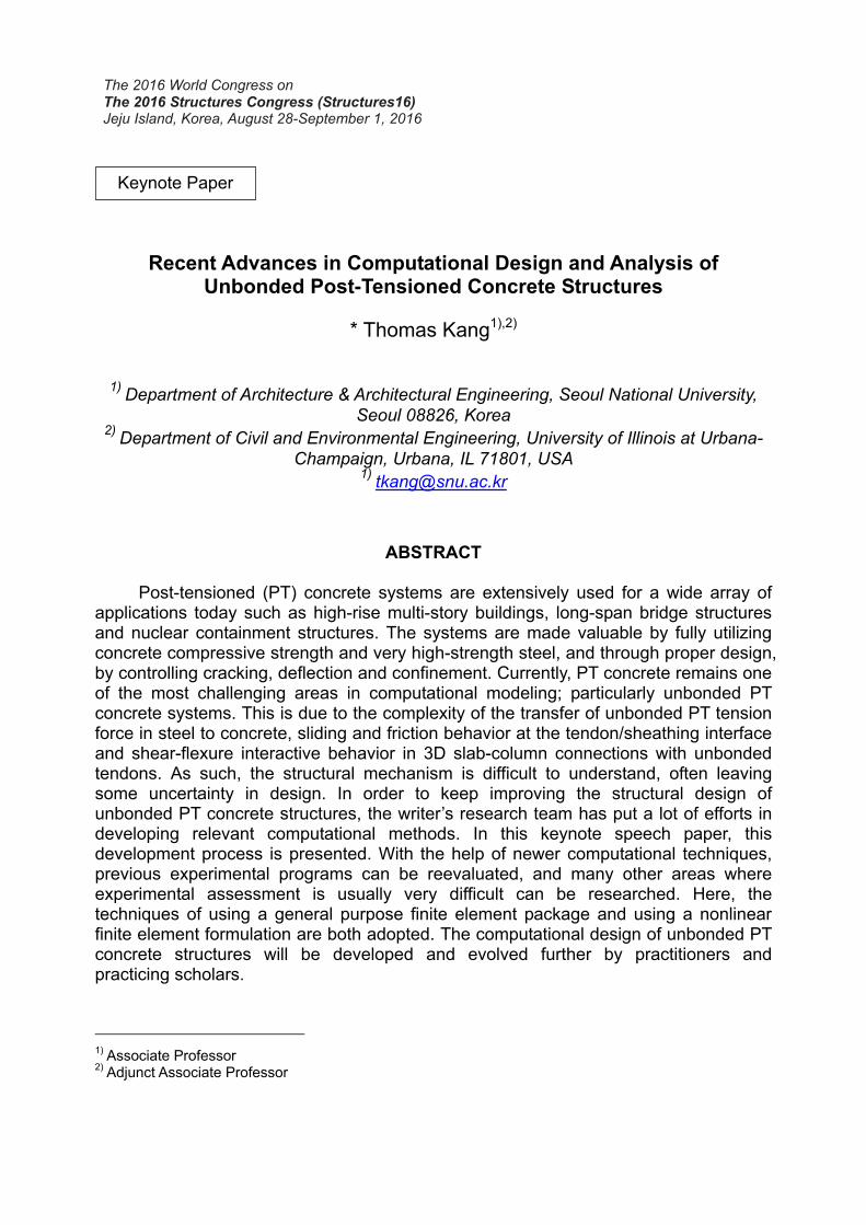
Recent Advances in Computational Design and Analysis of Unbonded Post-Tensioned Concrete Structures
* Thomas Kang1),2)
1) Department of Architecture & Architectural Engineering, Seoul National University, Seoul 08826, Korea
2) Department of Civil and Environmental Engineering, University of Illinois at Urbana-Champaign, Urbana, IL 71801, USA
ABSTRACT
Post-tensioned (PT) concrete systems are extensively used for a wide array of applications today such as high-rise multi-story buildings, long-span bridge structures and nuclear containment structures. The systems are made valuable by fully utilizing concrete compressive strength and very high-strength steel, and through proper design, by controlling cracking, deflection and confinement. Currently, PT concrete remains one of the most challenging areas in computational modeling; particularly unbonded PT concrete systems. This is due to the complexity of the transfer of unbonded PT tension force in steel to concrete, sliding and friction behavior at the tendon/sheathing interface and shear-flexure interactive behavior in 3D slab-column connections with unbonded tendons. As such, the structural mechanism is difficult to understand, often leaving some uncertainty in design. In order to keep improving the structural design of unbonded PT concrete structures, the writer’s research team has put a lot of efforts in developing relevant computational methods. In this keynote speech paper, this development process is presented. With the help of newer computational techniques, previous experimental programs can be reevaluated, and many other areas where experimental assessment is usually very difficult can be researched. Here, the techniques of using a general purpose finite element package and using a nonlinear finite element formulation are both adopted. The computational design of unbonded PT concrete structures will be developed and evolved further by practitioners and practicing scholars.
1) Associate Professor 2) Adjunct Associate Professor
Keynote Paper

1. INTRODUCTION Prestressed concrete is essential in many applications today in order to fully utilize concrete compressive strength, and through proper design, to control cracking and deflection. Generally, prestressed concrete can be constructed in one of three ways: pre-tensioned prestressed concrete, unbonded post-tensioned (PT) prestressed concrete, and bonded PT prestressed concrete. Although design methods have been developed for prestressed concrete over many decades, the understanding of structural mechanism in post-tensioned concrete members still needs to be greatly enhanced in many aspects such as shear-flexure interaction in post-tensioned two-way slab systems.
Finite element modeling applications to prestressed concrete have been researched for many decades since the pioneering works done by Ngo and Scordelis (1967). The key to simulating different types of prestressing systems lies in the modeling of bonding between tendons and the surrounding concrete. Tendons in a pre-tensioned member can be idealized to be perfectly bonded so that the principle of strain compatibility may be followed, and pre-tensioning can be modeled by specifying an initial temperature field or nonzero initial strain in tendons prior to applying service loads. This type of numerical modeling is relatively simple, and has been studied by many researchers (e.g., Stavroulaki et al. 1993; Kawakami and Ito 2003; Mercan et al. 2010). Conversely, the numerical simulation of either a bonded (before grouting) or unbonded post-tensioned member requires an unbonded formulation. Previous studies regarding such formulations have been performed by a handful of research groups (Kang and Scordelis 1980; Van Greunen and Scordelis 1983; El-Mezaini et al. 1991; El-Mezaini and Citipitioglu 1991; Nikolic and Mihanovic 1997; Vecchio et al. 2006). Kang and Scordelis (1980) and Van Greunen and Scordelis (1983) developed nonlinear iterative procedures for modeling both unbonded and bonded PT systems, which are limited to beam members only. Later, El-Mezaini et al. (1991), El-Mezaini and Citipitioglu (1991) and Vecchio et al. (2006) developed link elements to take into account the slip behavior of unbonded tendons. In particular, Vecchio et al. (2006) formulated a constitutive model for the slip behavior of both partially and fully unbonded tendons in PT beams and incorporated it into their nonlinear finite element algorithm. However, the applicability of this algorithm is limited to two-dimensional member cases and is not available for public use. In the current study, a series of numerical simulations is carried out by using a general purpose finite element analysis (FEA) package (ABAQUS 2014) to model the structural performance of a variety of PT concrete members. A practical and accurate modeling approach is developed and applied to the successful assessment of the performance of the PT members. With the developed modeling approach, it becomes possible to investigate their performance in relation with current design codes.
One of the main foci of this keynote speech paper is to briefly present the development process of a reliable general purpose finite element modeling approach for both bonded and unbonded post-tensioned concrete members. With the help of developed computational techniques, past experiments are robustly reproduced in such a way that the modeling is extended and applied in many other areas where experimental assessment is usually very difficult. Such a computational development
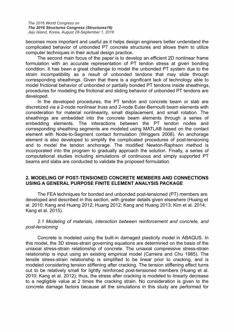
becomes more important and useful as it helps design engineers better understand the complicated behavior of unbonded PT concrete structures and allows them to utilize computer techniques in their actual design practice.
The second main focus of the paper is to develop an efficient 2D nonlinear frame formulation with an accurate representation of PT tendon stress at given bonding condition. It has been a great challenge to model the unbonded PT system due to the strain incompatibility as a result of unbonded tendons that may slide through corresponding sheathings. Given that there is a significant lack of technology able to model frictional behavior of unbonded or partially bonded PT tendons inside sheathings, procedures for modeling the frictional and sliding behavior of unbonded PT tendons are developed.
In the developed procedures, the PT tendon and concrete beam or slab are discretized via a 2-node nonlinear truss and 2-node Euler-Bernoulli beam elements with consideration for material nonlinearity, small displacement, and small rotation. The sheathings are embedded into the concrete beam elements through a series of embedding elements. The interactions between the PT tendon nodes and corresponding sheathing segments are modeled using MATLAB based on the contact element with Node-to-Segment contact formulation (Wriggers 2008). An anchorage element is also developed to simplify the complicated procedures of post-tensioning and to model the tendon anchorage. The modified Newton-Raphson method is incorporated into the program to gradually approach the solution. Finally, a series of computational studies including simulations of continuous and simply supported PT beams and slabs are conducted to validate the proposed formulation. 2. MODELING OF POST-TENSIONED CONCRETE MEMBERS AND CONNECTIONS USING A GENERAL PURPOSE FINITE ELEMENT ANALYSIS PACKAGE The FEA techniques for bonded and unbonded post-tensioned (PT) members are developed and described in this section, with greater details given elsewhere (Huang et al. 2010; Kang and Huang 2012; Huang 2012; Kang and Huang 2013; Kim et al. 2014; Kang et al. 2015).
2.1 Modeling of materials, interaction between reinforcement and concrete, and post-tensioning Concrete is modeled using the built-in damaged plasticity model in ABAQUS. In this model, the 3D stress-strain governing equations are determined on the basis of the uniaxial stress-strain relationship of concrete. The uniaxial compressive stress-strain relationship is input using an existing empirical model (Carreira and Chu 1985). The tensile stress-strain relationship is simplified to be linear prior to cracking, and is modeled considering tension stiffening after cracking. The tension stiffening effect turns out to be relatively small for lightly reinforced post-tensioned members (Huang et al. 2010; Kang et al. 2012); thus, the stress after cracking is modeled to linearly decrease to a negligible value at 2 times the cracking strain. No consideration is given to the concrete damage factors because all the simulations in this study are performed for

monotonic loading cases. For the uniaxial stress-strain behavior of non-prestressed mild steel, an elasto-
perfectly plastic model is used, while a nonlinear model is used for that of post-tensioning tendons. The nonlinear stress-strain relationship of Grade 270 seven-wire strands is used based on either the empirical model developed by Devalapura and Tadros (1992) or the tension test results. For computational purposes, the nonlinear stress-strain curve is split into piecewise linear segments. All the uniaxial nominal stress-strain relations are converted into true stress-strain relations.
All the non-prestressed reinforcement is modeled to be perfectly bonded to concrete, because the bar spacing is very large in typical post-tensioned concrete members. The constraint of perfect bonding is adopted in the model using the embedding technique. Nodes of the truss elements for a reinforcing bar embedded in concrete are enforced to meet displacement compatibility with nodes of the brick elements for the surrounding concrete, ensuring perfect bonding between the concrete and rebar.
The unbonded condition can be modeled by incorporating either the spring method (Huang et al. 2010; Kang et al. 2012) or a contact formulation (see Fig. 1), in which inequality constraints in the contact region are enforced by the penalty method. The spring method adopts spring elements (rigid beams) that allow for large rotation (Huang et al. 2010; Kang et al. 2012), but only the contact formation method is capable of simulating the behavior of bonded PT members and large sliding of tendons.
A tendon in a bonded PT member remains unbonded inside the plastic sheath at the post-tensioning stage. The tangential behavior of the contact surfaces is modeled to be frictionless, allowing the tendon to slip freely. The bonding condition is then simulated in the model using a contact formulation between the discretely modeled tendon and sheath (Fig. 1). The constitutive model for the tangential contact formulation is changed from being frictionless to infinitely rough. The Beam Multiple-Points Constraint (MPC), a built-in function in ABAQUS (2014), is applied at the anchorage so that a rigid beam is formed between the tendon end node and concrete node (Fig. 1).
Fig. 1 Modeling of bonded or unbonded PT tendons

The post-tensioning is simulated by coupling thermal expansion effects in the analysis. The uniformly distributed initial stress is produced by decreasing the temperature field of tendons. In this study, a separate analysis step is employed for the post-tensioning process itself. The frictionless condition is maintained in the following analysis steps. On the other hand, for the bonded tendons, the condition is changed to infinite friction after the post-tensioning.
Two kinds of elements are used in the finite element model. Each rebar is modeled separately and simulated by using a series of 3D 2-node linear truss elements (T3D2 in the ABAQUS element library), while the concrete members, anchor plates, and tendon ducts are formulated by using 3D 8-node linear brick elements with the reduced integration rule (C3D8R in the ABAQUS element library). Because bending stiffness may not be accurately modeled when the first-order elements are adopted with coarse meshing, at least five layers of the brick elements should be used over the slab thickness. As such, a typical element dimension used in the analysis ranges from 25 to 50 mm. Finally, the explicit dynamic procedure is utilized, where a sufficient loading time minimizes inertia effects and damps out transient responses.
2.2 Validation of developed finite element models Computational simulations are conducted to validate the proposed models for
both bonded and unbonded PT members. The prior test specimens used for the validation include two unbonded and one bonded PT beams, three unbonded and three bonded PT one-way slabs, and one bonded PT slab-column connection. Furthermore, an unbonded PT slab-column connection model is created just by manipulating the bond condition of tendons in the bonded connection model. The unbonded connection model is simulated for a comparison of moment transfer mechanisms between bonded and unbonded PT interior slab-column connections.
The comparisons are made between the experimental and computational results of load-center deflection relationship. The computational results of the beams tested by Mattock et al. (1971a) are depicted in Fig. 2, in which the contact formulation method is applied to both the bonded (RB1) and unbonded (RU1 and RU2) beams, while the spring method is applied only to the unbonded beams. The computational results are in good agreements with the experimental results. Slight differences between the experimental and computational results are noted from RB1 and RU2 in the inelastic redistribution range. The results of RU1 and RU2 validate the accuracy of both the contact formulation and spring methods for the unbonded PT beams. The damage patterns are also reproduced quite well. The distribution of four point loads changed after the inelastic redistribution of internal forces occurred, although the variation was not captured during the testing. The computational results exhibit a different extent of beam top damage underneath each loading point. Overall, the comparisons between the experimental and computational results show that the proposed model is quite accurate.

0 20 40 60 80 100 120 140 160
Mid-span deflection (mm)
0
10
20
30
40
50
RB1 Analysis (contact)RB1 Experiment
0 20 40 60 80 100 120 140 160
Mid-span deflection (mm)
0
10
20
30
40
50
RU2 Analysis (contact)RU2 Analysis (spring)RU2 Experiment
Fig. 2 Applied load versus mid-span deflection for bonded PT beam (RB1) and unbonded PT beams (RU1 and RU2)

0 10 20 30 40 50 60 70 80
Mid-span deflection (mm)
0
10
20
30
40
50
60
70
80
90
100
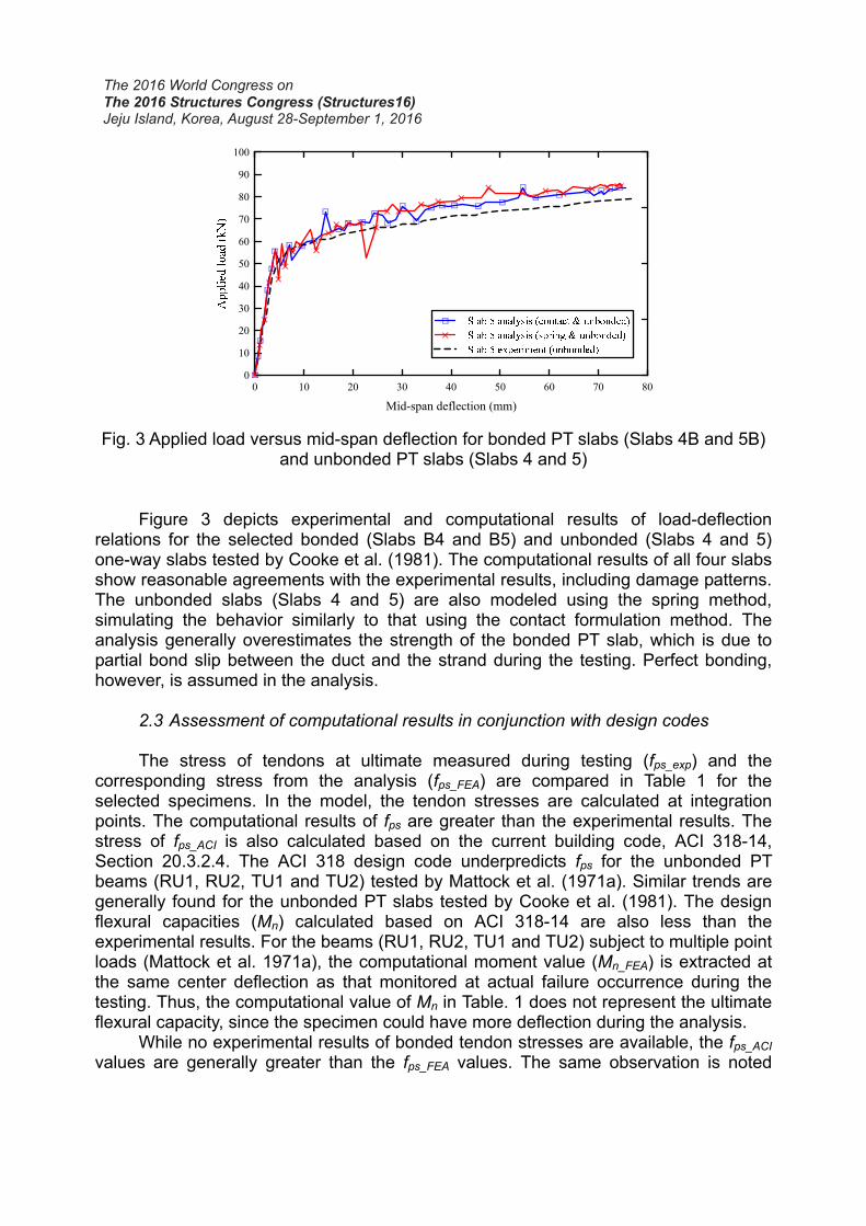
Fig. 3 Applied load versus mid-span deflection for bonded PT slabs (Slabs 4B and 5B)
and unbonded PT slabs (Slabs 4 and 5)
Figure 3 depicts experimental and computational results of load-deflection relations for the selected bonded (Slabs B4 and B5) and unbonded (Slabs 4 and 5) one-way slabs tested by Cooke et al. (1981). The computational results of all four slabs show reasonable agreements with the experimental results, including damage patterns. The unbonded slabs (Slabs 4 and 5) are also modeled using the spring method, simulating the behavior similarly to that using the contact formulation method. The analysis generally overestimates the strength of the bonded PT slab, which is due to partial bond slip between the duct and the strand during the testing. Perfect bonding, however, is assumed in the analysis.
2.3 Assessment of computational results in conjunction with design codes The stress of tendons at ultimate measured during testing (fps_exp) and the
corresponding stress from the analysis (fps_FEA) are compared in Table 1 for the selected specimens. In the model, the tendon stresses are calculated at integration points. The computational results of fps are greater than the experimental results. The stress of fps_ACI is also calculated based on the current building code, ACI 318-14, Section 20.3.2.4. The ACI 318 design code underpredicts fps for the unbonded PT beams (RU1, RU2, TU1 and TU2) tested by Mattock et al. (1971a). Similar trends are generally found for the unbonded PT slabs tested by Cooke et al. (1981). The design flexural capacities (Mn) calculated based on ACI 318-14 are also less than the experimental results. For the beams (RU1, RU2, TU1 and TU2) subject to multiple point loads (Mattock et al. 1971a), the computational moment value (Mn_FEA) is extracted at the same center deflection as that monitored at actual failure occurrence during the testing. Thus, the computational value of Mn in Table. 1 does not represent the ultimate flexural capacity, since the specimen could have more deflection during the analysis.
While no experimental results of bonded tendon stresses are available, the fps_ACI values are generally greater than the fps_FEA values. The same observation is noted

Table 1. Tendon stress at ultimate and nominal moment strength
fse_exp (MPa)
fps_ACI (MPa)
fps_exp (MPa)
fps_FEA (MPa)
Mn_ACI†
(kN-m) Mn_exp (kN-m)
Mn_FEA†
(kN-m)
RB1 1,297.6 1,703.1 N.A. 1,607.2 75.5 93.5 74.6
RU1 1,262.5 1,385.2 1,434.8 1,475.5 74.3 79.9 64.5
RU2 1,286.6 1,409.3 1,414.9 1,461.7 73.7 77.9 66.2
TB1 1,261.1 1,821.7 N.A. - 94.4 110.0 -
TU1 1,259.0 1,672.7 1,794.8 - 111.8 124.9 -
TU2 1,252.1 1,663.8 1,747.9 - 93.2 102.3 -
CB1 N.A. 1,821.7 N.A. - 94.4 91.8 -
CU1 1,329.4†† 1,741.0 N.A. - 100.6 114.6 -
CU2 1,334.2†† 1,724.4 N.A. - 96.1 95.3 -
CB1* N.A. 1,703.1 N.A. - 75.5 102.0 -
CU1* 1,352.1†† 1,463.8 N.A. - 76.7 87.5 -
CU2* 1,290.7†† 1,435.5 N.A. - 74.5 91.3 -
Slab 1 1,165.3 1,280.4 1,351.4 - 36.0 38.9‡ -
Slab 2 1,144.6 1,305.2 1,365.2 - 40.3 37.9‡ -
Slab 3 1,199.7 1,613.4 1,461.7 - 22.0 15.0‡ -
Slab 4 1,165.3 1,286.6 1,379.0 1,451.4 37.0 41.7‡ 38.7
Slab 5 1,151.5 1,325.2 1,441.1 1,537.6 41.2 43.5‡ 45.7
Slab 6 1,220.4 1,618.3 1,572.1 1,570.7 22.1 19.2‡ 20.4
Slab 7 1,165.3 1,281.1 1,420.4 - 36.2 42.9‡ -
Slab 8 1,165.3 1,328.0 1,489.3 - 41.0 45.6‡ -
Slab 9 1,206.6 1,618.3 1,606.5 - 22.1 24.1‡ -
Slab B4 1,199.7 1,765.8 N.A. 1,570.7 41.1 40.6‡ 42.4
Slab B5 1,165.3 1,765.8 N.A. 1,710.6 49.4 44.8‡ 50.3
Slab B6 1,241.1 1,765.8 N.A. 1,882.3 23.7 21.6‡ 22.0
fse_exp = experimentally measured effective tendon stress fps_exp = nominal tendon stress experimentally measured by using load cell at the end of tendon (For Slabs 1 to 9, load cell was placed at opposite tendon end of the jacking point). fps_FEA = nominal tendon stress analytically monitored at middle integration point of tendon
elements. † Calculated based on the corresponding fps ‡ Taken from reported load-deflection curves (not from reported table)
* at center support †† Estimated - Specimens not analyzed N.A. = Not Available

from the flexural capacity prediction according to ACI 318-14. Conversely, the computational flexural capacities are generally greater than the experimental flexural capacities in the bonded slabs (see Fig. 3). This is due to partial bond slip between the strand and sheath during the testing. The opposite result is shown only for RB 1 (Fig. 2). As mentioned, the experimental value is based on the distribution of four “equal” point loads. The equal point loads, however, are unlikely.
The developed modeling approach is also taken to simulate the lateral load behavior of PT interior slab-column connections. The distribution and redistribution of stresses at the slab-column connection are very complicated; thus, combined numerical and experimental investigations would benefit the understanding of the moment transfer mechanism and shear stress variation at a PT interior slab-column connection with either unbonded or bonded tendons.
In the analysis, the top of the column of the specimen tested by Warnitchai et al. (2004) is laterally displaced up to 2% drift, which was the maximum value during testing. The lateral load-drift relations of the two models with unbonded and bonded tendons are compared in Fig. 4, with the backbone envelope of the test data. The experimental and computational results of the lateral stiffness and strength are reasonably matched. The post-yield stiffness is a little under-predicted, possibly due to the nature of tolerance during the construction of the specimen. The computational results between the bonded and unbonded PT connections are quite close. The strain distributions of a top re-bar and a tendon are also compared for selected locations at different drift ratios (Fig. 5). The comparisons between the experimental and computational results exhibit reasonably good agreement. The strain distribution pattern along the re-bar is well reproduced by the computational model. The difference could be due to the monotonic versus cyclic loading and bond deterioration between the strand and duct. The larger values of simulated strains at 1.5% and 2% drift ratios are caused by the perfect bonding condition, which is unlikely to be retained under large deformation reversals. It is concluded that the computational model reproduces the behavior of PT interior slab-column connections quite well.
Fig. 4 Lateral force versus story drift for bonded slab-column connection without drop panel tested by Warnitchai et al. (2004) and for analytical models of bonded and unbonded slab-column connections

Distance from the center of the column (mm)
0
0 500 1000 1500 2000-2000 -1500 -1000 -500
2
4
6
8
10
× 10-4
Str
ain
Analysis (drift ratio = 2.00%)Experiment (drift ratio = 2.00%)Analysis (drift ratio = 1.50%)Experiment (drift ratio = 1.50%)Analysis (drift ratio = 1.25%)Experiment (drift ratio = 1.25%)Analysis (drift ratio = 1.00%)Experiment (drift ratio = 1.00%)Analysis (drift ratio = 0.75%)Experiment (drift ratio = 0.75%)Analysis (drift ratio = 0.50%)Experiment (drift ratio = 0.50%)Analysis (drift ratio = 0.25%)Experiment (drift ratio = 0.25%)
Fig. 5 Strain distributions of bonded PT tendon at slab-column connection
Fig. 6 Average shear stress at interior slab-column connection in computational model
Shear stress inside a slab is typically not obtainable from experiments. The shear stress at the critical section defined in Section 22.6.4.1 of ACI 318-14 is examined according to the procedure shown in Fig. 6, where the average shear stress over five layers of elements is computed. The shear stress distribution around the critical section corresponds to the eccentric shear stress model. The shear stress values of 23 (see Fig. 6) at the two corner points of the critical section are close to each other (Fig. 7).

The maximum stress of 0.39√f’c (in MPa) is monitored at about 1% drift, which is slightly larger than the ACI 318 punching shear capacity (vc) of 0.37√f’c (in MPa) (Eq. 22.6.5.5 of ACI 318-14), and is maintained for increased drift levels. In the experiment, the bonded PT connection failed in punching shear at a drift ratio of about 2%.
0.37 ' (ACI 318-14)cf
Fig. 7 Shear stress versus drift ratio from computational results
2.0% 1.6% 1.2%
0.8% 0.4% 0.0%
Bonded Unbonded
Fig. 8 Shear stress distributions at critical section for each drift ratio

Fig. 9 Factor of v versus drift ratio from computational results
A small discrepancy (prior to punching) is noted between the computational results of the bonded and unbonded connections (Figs. 7 and 8). This finding is of value, as no experimental studies have revealed it to date. Only the tensile stress distribution along the tendon is different between the bonded and unbonded cases, which is not constant for the bonded case as shown in Fig. 5.
Additionally, the fraction of unbalanced moment transferred in eccentricity of shear (v) is examined on the basis of the eccentric shear stress model and computational results of direct shear force (Vu) and unbalanced moment (Mu,unb) at each drift ratio. Figure 9 depicts v at the critical section of the bonded and unbonded PT connections. The value of v corresponds to the ACI 318 specified value of 0.47 (Fig. 9), and negligible difference is noticed between the bonded and unbonded connections. It is concluded that the ACI codes regarding the factor of v are reasonable for both bonded and unbonded PT interior connections. Such a computational assessment is important particularly when there is difficulty in monitoring shear stresses inside a slab. 3. DEVELOPMENT OF 2D NONLINEAR FINITE ELEMENT FORMULATION FOR UNBONDED POST-TENSIONED CONCRETE MEMBERS
The 2D nonlinear finite element formulation for bonded, partially bonded and unbonded post-tensioned (PT) members is developed and described in this section, with greater details given elsewhere (Huang 2012).
3.1 Discretization schemes This section briefly discusses the discretization schemes employed to assemble a
PT member in this study. A typical PT beam is discretized into a series of engineering

elements as shown in Fig. 10. The black thicker line represents the reference location of the beam element which discretizes the beam without PT tendons. The PT tendons are modeled via a series of first-order truss elements rendered as red parabolic lines in Fig. 10. The dotted lines represent the embedding elements which are in fact the rigid beam elements. The embedding elements ensure that the prestress induced load and moment are appropriately transferred to the reference location of the PT beam. The anchorage element located at either end of the PT beam contains one node from a tendon element and the other node from an embedding element (blue solid lines at the end of the beam in Fig. 10). A typical contact element contains three nodes with eight degrees-of-freedom. Among the three nodes, the first two of them are from neighboring embedding elements and the last one belongs to the prestressing tendon; therefore, the tendon node is confined in the segment (sheathing) created from the first two nodes of the contact element (dotted circle in Fig. 10). On the basis of the discretization schemes, a Node-to-Segment (NTS) contact formulation (Wriggers 2008) was employed and presented in depth elsewhere (Huang 2012).
Fig. 10 Finite element discretization scheme for post-tensioned concrete member
3.2 Computational analysis The Post-Tensioning Institute (PTI 2006) suggests an analytical equation to
compute friction loss, which is used to compute the hand calculation solutions with and without wobble effect. These solutions are then used for comparison with computational solutions. An imaginary, simply-supported 15.2 m long PT beam is used in this analysis as shown in Fig. 11. The finite element model consists of 20 beam elements, 21 embedding elements, 21 truss elements, 20 contact elements, and an anchorage element. The anchor slip is assumed to be 0.5 mm in this case for illustrative purposes. The friction coefficient is assumed to be 0.3 for seven-wire strands, which yields a partially bonded interface in this simulation. The wobble effect is neglected in the simulation and its solution.

Fig. 11 Imaginary simply supported PT beam
0 200 400 600 800 1000 1200 1400 1600
Beam location at longitudinal direction (mm)
1300
1325
1350
1375
1400
1425
1450
Pre
stre
ss (
MP
a)
Hand calculation (before setting)Computational (before setting)Hand calculation (after setting = 0.5 mm)Computational (after setting = 0.5 mm)
Fig. 12 Prestress loss before and after wedge setting from computational results and hand calculation solutions
The friction loss obtained from the computational model is 67.6 MPa at the dead end. The computational prestress loss over the beam is plotted in Fig. 12. The reverse movement of a tendon due to anchor slip produces a prestress loss at the live end. Figure 12 depicts very good agreements between the computational result and hand calculation using the PTI equation. This comparison validates the formulation of frictional contact.
The prestress loss due to the tendon profile and wobble effect (unintended curvature) are essentially from the same source, that is, curvature. The wobble coefficient ( k ) is assumed to be uniformly distributed over the length. The assumed k

is converted into extra tendon curvatures by imposing additional short-wave sine shape on the existing tendon profile, so that the total angular change becomes equal to ( ) /kx . Here, is the friction coefficient, is the angle change and x is the distance. Conversely, the developed finite element formulation uses only the friction coefficient of .
Fig. 13 Prestress loss from computational results and hand calculation solutions for Specimen #2 tested by Burns et al. (1991) [Note that hand calculation solutions are
from Burns et al. (1991).]
One continuous two-span PT beam tested by Burns et al. (1991) is selected for investigation (Fig. 13). Details of the test program are available in the paper by Burns et al. (1991). The computational model consists of 47 beam elements, 48 embedding elements, 48 truss elements, 47 contact elements, and one anchorage element per specimen. The friction and wobble coefficients are set equal to 0.07 and 0.001 as recommended by Burns et al. (1991). Figure 13 compares the computational prestress loss distributions and corresponding hand calculation by Burns et al. (1991), from which very good agreements are shown. These solutions are slightly greater than the measured friction losses of 20 kN (Specimen #2)). Perhaps, the experimental data contain uncertain factors such as measurement error.
Additionally, two imaginary simulations with of 0.07 and k of 0.001 and with no friction are performed for Specimen #2. Although as anticipated the prestress distributions are quite different, the global flexural behaviors are interestingly the same (Figs. 14 and 15). Interestingly, the friction has little to no effects on the flexural behavior/strength.
Next, two simply-supported one-way PT slabs (Slab 4 and Slab 5) tested by Cooke et al. (1981) are also simulated using the developed formulation. The results of the simulations are also compared with the results made through the general purpose finite element package of ABAQUS, where the perfectly unbonded condition is assumed. The overall behavior is presented in Figs. 16 and 17. The developed

formulation predicts the behavior of Slab 4 quite accurately, while the behavior of Slab 5 is slightly overestimated in terms of the yield strength and post-yield behavior as is the case with the ABAQUS package (Kang et al. 2015). Nonetheless, the developed formulation accurately captures the bilinear characteristics.
-2 0 2 4 6 8 10 12 14 16 18 20
Deflection at middle of the first span (mm)
0
50
100
150
200
250
Frictional contact, µ = 0.07 k = 0.001)Frictionless contact, µ = 0 k = 0)
Fig. 14 Applied load versus middle deflection for computational models with and without
friction
Fig. 15 Prestress distribution for computational models with and without friction

0 0.01 0.02 0.03 0.04 0.05 0.06 0.07 0.08
Mid-span deflection (mm)
0
20
40
60
80
100
Tot
al a
ppli
ed lo
ad (
kN)
Slab 4 experimentSlab 4 current simulationSlab 4 ABAQUS
Fig. 16 Total applied load versus mid-span deflection for Slab 4 tested by Cooke et al.
(1981) [Note that Slab 4 ABAQUS analysis without friction effect is from Fig. 3.]
Fig.17 Total applied load versus mid-span deflection for Slab 5 tested by Cooke et al. (1981) [Note that Slab 4 ABAQUS analysis without friction effect is from Fig. 3.]
4. CONCLUSIONS
First, sophisticated computational modeling within a general purpose finite element package was used as a tool for investigating the behavior of both bonded and (perfectly) unbonded post-tensioned (PT) concrete structures and improving the current design. The previous test results are used to verify that the developed modeling approach reproduces the structural behavior quite well. Based on the computational research, the following conclusions related to the analysis and design of unbonded PT concrete structures are drawn:

(1) The general FEA approach, through proper boundary and material approximation/assumption, is capable of reproducing the behavior of bonded and unbonded PT concrete members. The FEA approach can contribute to a variety of design problems associated with unbonded PT concrete structures, particularly in cases where internal measurements are not obtainable from experimental studies.
(2) With the exception of the lateral drift ratio at punching, the FEA approach verifies that the lateral stiffness and strength as well as the shear stress distribution around the slab-column connection are not much impacted by the bond condition of tendons.
(3) The FEA approach reconfirms that the existing eccentric shear stress model and relevant punching shear design codes are valid.
Next, a finite element contact formulation was developed to model bonded,
partially bonded, and unbonded PT members. The interface of PT tendons and sheathings was modeled through a Node-to-Segment contact formulation. The developed finite element formulation was implemented into a nonlinear finite element program developed using MATLAB, and verified by performing several examples. The developed FE formulation can be extended to a variety of computational studies such as the bond stress along the tendon/sheathing interface at different levels of bonding. In this case, advanced constitutive models should be implemented at the contact interface.
5. ACKNOWLEDGEMENTS
This keynote speech paper is a revised and reorganized version of the previous two publications that the writer mentored as a doctoral advisor and produced as Lead Author: the thesis entitled “Finite Element Method for Post-Tensioned Prestressed Concrete Structures” and the ACI Structural Journal paper entitled “Experimental and Numerical Assessment of Bonded and Unbonded Post-Tensioned Concrete Members.” The writer acknowledges the various contributions from the author/co-authors of the thesis and the journal paper, particularly from his former PhD student, Dr. Yu Huang. REFERENCES ABAQUS. (2014), Abaqus/CAE User's Guide, Providence, RI. ACI Committee 318. (2014), Building Code Requirements for Structural Concrete (ACI
318-14) and Commentary (ACI 318R-14), American Concrete Institute, Farmington Hills, MI, 519.
Burns, N. H.; Helwig, T.; and Tsujimoto, T. (1991), “Effective Prestress Force in Continuous Post-Tensioned Beams with Unbonded Tendons.” ACI Struct. J., Vol. 88(1), 84-90.
Carreira, D. J., and Chu, K. H. (1985), “Stress-Strain Relationship for Plain Concrete in Compression.” ACI J., Vol. 83(6), 797-804.
Cooke, N.; Park, R.; and Yong, P. (1981), “Flexural Strength of Prestressed Concrete

Members with Unbonded Tendons.” PCI J., Vol. 26(6), 52-79. Devalapura, R. K., and Tadros, M. K. (1992), “Critical Assessment of ACI 318 Eq. (18-3)
for Prestressing Steel Stress at Ultimate Flexure.” ACI Struct. J., Vol. 89(5), 538-546. El-Mezaini, N.; Balkaya, C.; and Çitipitioǧlu, E. (1991), “Analysis of Frames with
Nonprismatic Members.” J. Struct. Eng., ASCE, Vol. 117(6), 1573-1592. El-Mezaini, N., and Çitipitioǧlu, P. (1991), “Finite Element Analysis of Prestressed and
Reinforced Concrete Structures.” J. Struct. Eng., Vol. 117(10), 2851-2864. Huang, Y. (2012), “Finite Element Method for Post-Tensioned Prestressed Concrete
Structures.” Ph.D. thesis, The University of Oklahoma, Norman, OK, 326. Huang, Y.; Kang, T. H.-K.; Ramseyer, C.; and Rha, C. (2010), “Background to Multi-
Scale Modelling of Unbonded Post-Tensioned Concrete Structures.” Int. J. Theor. Appl. Multiscale Mech., Vol 1(3), 219-230.
Kang, T. H.-K., and Huang, Y. (2012), “Nonlinear Finite Element Analyses of Unbonded Post-Tensioned Slab-Column Connections.” PTI J., Vol. 8(1), 4-19.
Kang, T. H.-K., and Huang, Y. (2013), “Corner Post-Tensioned Slab-Column Connections.” PTI J., Vol. 9(1), 1-15.
Kang, T. H.-K., Huang, Y., Shin, M., Lee, J. D., and Cho, A. S. (2015) “Experimental and Numerical Assessment of Bonded and Unbonded Post-Tensioned Concrete Members,” ACI Struct. J., Vol. 112(6), 735-748.
Kang, Y.-J., and Scordelis, A. C. (1980), “Nonlinear Analysis of Prestressed Concrete Frames.” J. Struct. Div., ASCE, Vol. 106(ST2), 445-462.
Kawakami, M., and Ito, T. (2003), “Nonlinear Finite Element Analysis of Prestressed Concrete Members Using ADINA.” Comp. & Struct., Vol. 81(8), 727-734.
Kim, U., Huang, Y., Chakrabarti, P., and Kang, T. H.-K. (2014), “Modeling of Post-Tensioned One-Way and Two-Way Slabs with Unbonded Tendons,” Comp. & Struct., Vol. 13(5), 547-561.
MATLAB language (2010), Download Manual MATLAB 2010, MathWorks, Natick, MA. Mattock, A. H.; Yamazaki, J.; and Kattula, B. T. (1971), “Comparative Study of
Prestressed Concrete Beams, with and without Bond.” ACI J., Vol 68(2), 116-125. Mercan, B., Schultz, A. E., and Stolarski, H. K. (2010), “Finite element modeling of
prestressed concrete spandrel beams.” Eng. Struct., Vol. 32(9), 2804-2813. Ngo, D., and Scordelis, A. C. (1967), “Finite Element Analysis of Reinforced Concrete
Beams.” ACI J., Vol. 64(3), 152-163. Nikolic, Z., and Mihanovic, A. (1997), “Non-linear Finite Element Analysis of Post-
Tensioned Concrete Structures.” Eng. Comput., Vol. 14(5), 509-528. PTI (2006), Post Tensioning Manual – Six Edition, Post Tensioning Institute, Phoenix,
AZ, 254. Stavroulaki, G.; Stavroulakis, G. E.; and Leftberis, B. (1993), “Modelling Prestress
Restoration of Buildings by General Purpose Structural Analysis and Optimization Software, The Optimization Module of MSC/NASTRAN.” Comput. Struct., Vol. 62(1), 81-92.
Van Greunen, J., and Scordelis, A. C. (1983), “Nonlinear Analysis of Prestressed Concrete Slabs.” J. Struct. Eng., ASCE, Vol. 109(7), 1742-1760.
Vecchio, F. J.; Gauvreau, P.; and Liu, K. (2006), “Modeling of Unbonded Post-Tensioned Concrete Beams Critical in Shear.” ACI Struct. J., Vol. 103(1), 57-64.
Warnitchai, P.; Pongpornsup, S.; Prawarwong, U.; and Pimanmas, A. (2004), “Seismic Performance of Post-Tensioned Interior Flat Slab-Column Connections”, New Technologies for Urban Safety of Mega Cities in Asia, 2004, Agra, India, 10.
Wriggers, P. (2008), Nonlinear Finite Element Methods, 1st Ed., Springer, New York, NY, 572.