Embed Size (px)
Citation preview
Recent Euclid Wakefield Experiments @ AWA
C. Jing, S. Antipov, A. Kanareykin, P. Schoessow, Euclid Techlabs, LLCM. Conde, W. Gai, W. Liu, J. Power, Z. Yusof, HEP, ANL
HG Workshop, Feb. 2011
2
I. Experiment on Transformer Ratio Enhancement Using a Ramped Bunch Train
3
Wakefield Transformer Ratio
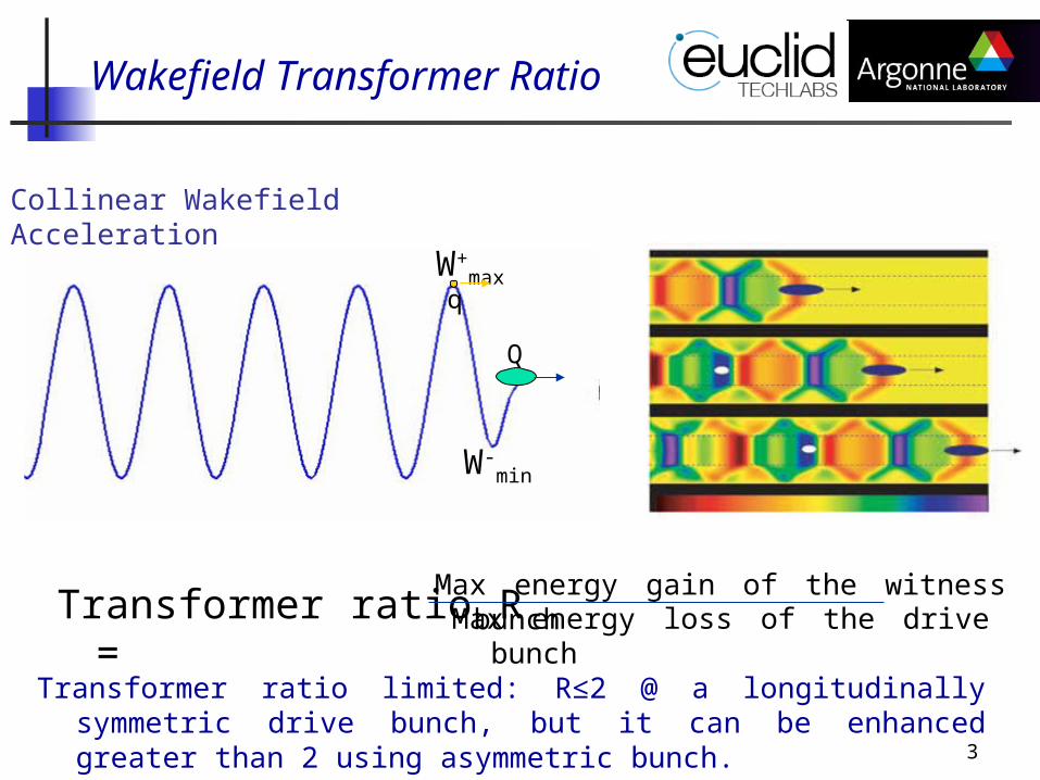
Transformer ratio limited: R≤2 @ a longitudinally symmetric drive bunch, but it can be enhanced greater than 2 using asymmetric bunch.
Transformer ratio R =Max energy gain of the witness bunch
Max energy loss of the drive bunch
Q
W-min
W+max
q
Collinear Wakefield Acceleration
4
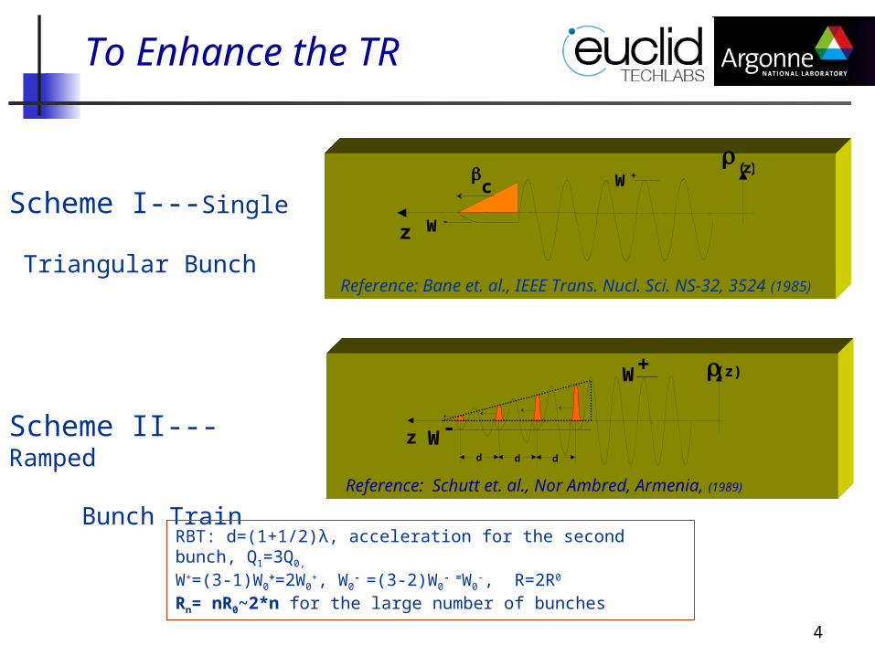
Scheme I---Single Triangular Bunch
Scheme II---Ramped Bunch Train
Reference: Schutt et. al., Nor Ambred, Armenia, (1989)
Reference: Bane et. al., IEEE Trans. Nucl. Sci. NS-32, 3524 (1985)
c (z)
W+
W-z
To Enhance the TR
zd d
W -
W+
d
(z)
RBT: d=(1+1/2)λ, acceleration for the second bunch, Q1=3Q0, W+=(3-1)W0
+=2W0+, W0
- =(3-2)W0- =W0
-, R=2R0
Rn= nR0~2*n for the large number of bunches
5
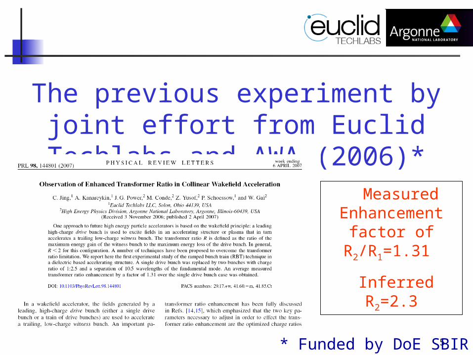
The previous experiment by joint effort from Euclid Techlabs and AWA (2006)*
Measured Enhancement
factor of R2/R1=1.31
Inferred R2=2.3
* Funded by DoE SBIR Phase II
6
The latest experiment by joint effort from Euclid Techlabs and AWA (2010)*
What’s the same comparing to the previous experiment? Same Ramped Bunch Train Technique. Same DLA Structure
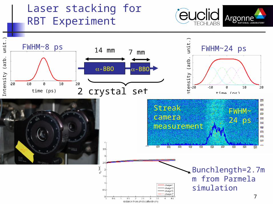
What’s new comparing to the previous experiment? Laser stacking technique to elongate the bunch
length of AWA beam. Improved data taking conditions (upgraded LLRF, remotely
controlled delay line for the witness bunch, independent controlled shutter for each bunch, etc.)
*Results will appear in PRSTAB soon.
7
time (ps)
Inte
nsi
ty (
arb
. u
nit.
)
20 10 0 10 20time (ps)
Inte
nsi
ty (
arb
. u
nit.
)
20 10 0 10 20
7 mm
-BBO-BBO
14 mm
2 crystal set
Laser stacking for RBT Experiment
FWHM~24 ps
FWHM~8 ps FWHM~24 ps
Streak camera measurement
Bunchlength=2.7mm from Parmela simulation
8
Measurement
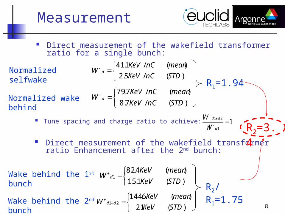
Direct measurement of the wakefield transformer ratio for a single bunch:
)(/5.2
)(/1.41
STDnCKeV
meannCKeVW dNormalized selfwake
)(/7.8
)(/7.79
STDnCKeV
meannCKeVW dNormalized wake behind
R1=1.94
Tune spacing and charge ratio to achieve: 11
21
d
dd
W
W
Direct measurement of the wakefield transformer ratio Enhancement after the 2nd bunch:
)(21
)(6.14421
STDKeV
meanKeVW dd
Wake behind the 1st bunch
)(1.15
)(4.821
STDKeV
meanKeVW d
R2/R1=1.75Wake behind the 2nd bunch
R2=3.4
9
II. Experiment on the 1st Tunable DLA Structure*
* Funded by DoE SBIR Phase II
10
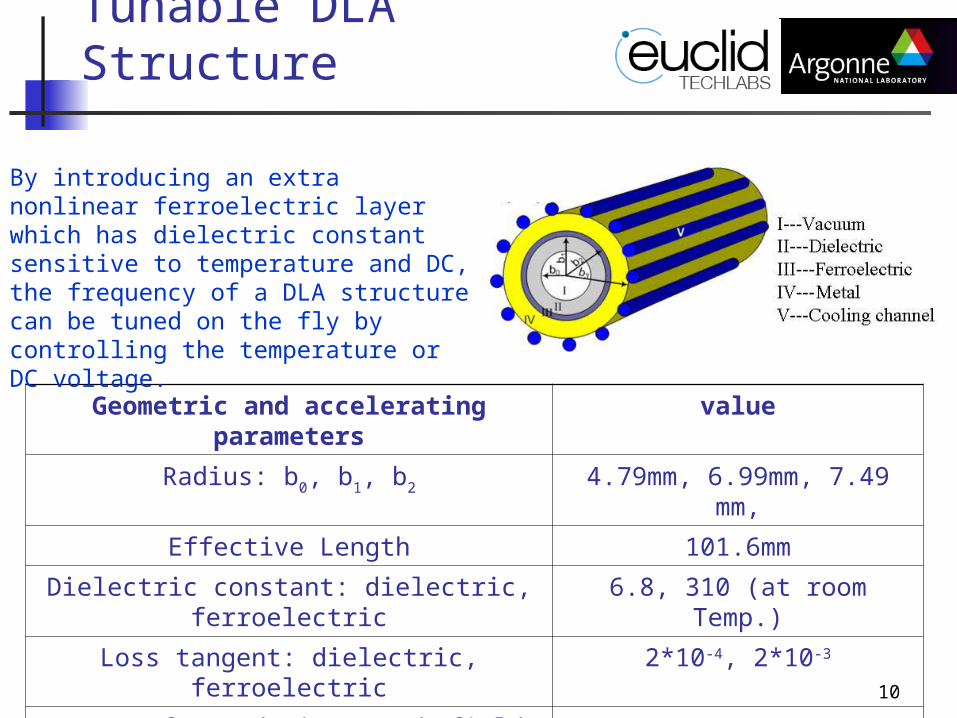
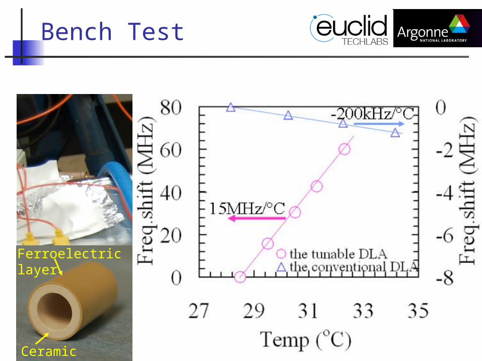
Geometric and accelerating parameters value
Radius: b0, b1, b2 4.79mm, 6.99mm, 7.49 mm,
Effective Length 101.6mm
Dielectric constant: dielectric, ferroelectric 6.8, 310 (at room Temp.)
Loss tangent: dielectric, ferroelectric 2*10-4, 2*10-3
Freq. of two dominant wakefield modes 7.8GHz, 14.1GHz (at room Temp.)
Q of two dominant wakefield modes 385, 1250
Peak wakefield by 50nC drive bunch (z=2.3mm) 16MeV/m
Tunable DLA Structure
By introducing an extra nonlinear ferroelectric layer which has dielectric constant sensitive to temperature and DC, the frequency of a DLA structure can be tuned on the fly by controlling the temperature or DC voltage.
11
Ferroelectric layer
Ceramic layer
Bench Test
12
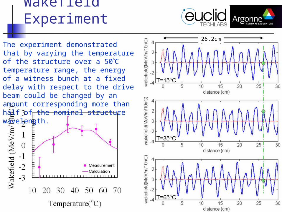
Wakefield Experiment
The experiment demonstrated that by varying the temperature of the structure over a 50C temperature range, the energy of a witness bunch at a fixed delay with respect to the drive beam could be changed by an amount corresponding more than half of the nominal structure wavelength.
26.2cm

13
Bench Test---DC Voltage
Although introduction of a high DC voltage to a tunable DLA structure in the vacuum environment appears to be challenging at this moment, this approach is still attractive because of its extremely short response time compared to the temperature control. One can conclude the best solution for the future tunable DLA structures would be a combination of ”coarse” but slow temperature tuning by 100s of MHz and rapid fine tuning with high voltage dc biasing applied.
14
Summary
•Wakefield transformer ratio of 3.4 has been achieved in the recent experiment at AWA facility with help of the elongated bunch length.
•A novel low loss BSTM ferroelectric material has been used in dielectric based accelerators as a method of frequency tuning. Wakefield acceleration experiment show an excellent tuning capability through control of either temperature.