Embed Size (px)
Citation preview

Recent results of ECRH/ECCD experiments on TCV
Felici, F.A.A.; Asp, E.; Cirant, S.; Coda, S.; Fable, E.; Goodman, T.P.; Graves, J.; Henderson,M.; Paley, J.I.; Sauter, O.; Turri, G.; Udintsev, V.S.; Zucca, C.Published in:Proceedings of the 18th International Toki conference, December 9-12, 2008, Gifu, Japan
Published: 01/01/2008
Document VersionAccepted manuscript including changes made at the peer-review stage
Please check the document version of this publication:
• A submitted manuscript is the author's version of the article upon submission and before peer-review. There can be important differencesbetween the submitted version and the official published version of record. People interested in the research are advised to contact theauthor for the final version of the publication, or visit the DOI to the publisher's website.• The final author version and the galley proof are versions of the publication after peer review.• The final published version features the final layout of the paper including the volume, issue and page numbers.
Link to publication
Citation for published version (APA):Felici, F., Asp, E., Cirant, S., Coda, S., Fable, E., Goodman, T. P., ... Zucca, C. (2008). Recent results ofECRH/ECCD experiments on TCV. In Proceedings of the 18th International Toki conference, December 9-12,2008, Gifu, Japan
General rightsCopyright and moral rights for the publications made accessible in the public portal are retained by the authors and/or other copyright ownersand it is a condition of accessing publications that users recognise and abide by the legal requirements associated with these rights.
• Users may download and print one copy of any publication from the public portal for the purpose of private study or research. • You may not further distribute the material or use it for any profit-making activity or commercial gain • You may freely distribute the URL identifying the publication in the public portal ?
Take down policyIf you believe that this document breaches copyright please contact us providing details, and we will remove access to the work immediatelyand investigate your claim.
Download date: 18. May. 2018

Recent results of ECRH/ECCD
experiments on TCVF. Felici, E. Asp, S. Cirant1, S.Coda, E. Fable, T.P. Goodman, J. Graves,
M. Henderson2, J.I. Paley, O. Sauter, G. Turri, V. Udintsev, C. Zucca
and the TCV Team
Centre de Recherches en Physique des Plasmas
Ecole Polytechnique Fédérale de Lausanne, Switzerland
Association EURATOM-Swiss Confederation
1) Istituto della Fisica del Plasma, EURATOM-ENEA-CNR Association, Milano, Italy2) ITER Organization, Cadarache, Franceb
18th International Toki conference, December 9-12, 2008, Gifu, Japan 2
Talk outlineTCV Tokamak overview and features− ECH/ECCD system
− Real-time control
Recent results of ECH/ECCD experiments− Real-time control of
Sawtooth periodPeak-in-profile
− Plasmas with internal electron transport barriers (eITBs) Creation and sustainment in steady-stateSteady-state 100% bootstrap currentGlobal oscillations, suppression using current density profile perturbations
− Tearing mode studies
Conclusions & Summary

18th International Toki conference, December 9-12, 2008, Gifu, Japan 3
TCV OverviewTCV: Tokamak à Configuration Variable
R/a = 0.88m/0.25m,
BT < 1.45T, Ip < 1.2MA
High flexibility in plasma shape/position
0.9 < elongation < 2.8
-0.6 < triangularity < 0.9
tpulse < 4s, Te< 10keV
Graphite inner wall

18th International Toki conference, December 9-12, 2008, Gifu, Japan 4
Flexible ECH/ECCD system
Side launch ECH, ECCDncut-off ≈ 4×10¹⁹ m-3
Top launch ECHncut-off ≈ 1020 m-3
2nd harmonic X2 (82.7GHz)6 x 0.5MW, 2s gyrotrons
3rd harmonic X3 (118GHz)3 x 0.5MW, 2s gyrotrons
Illustration of possibleX2 toroidal injection angles

18th International Toki conference, December 9-12, 2008, Gifu, Japan 5
Real-time control of EC systemDigital real-time feedback control of EC system
EC power/mirror angles can be controlled in Real-time. [Paley, PPCF2007]
Recently, injection angle was regulated to control− Sawtooth period
− Peak-in-profile

18th International Toki conference, December 9-12, 2008, Gifu, Japan 6
Control of sawtooth periodSawtooth crashes – periodic core pressure and temperature drop inside q=1 surface.− Control is important as sawteeth can trigger NTMs -> confinement loss
Period can be controlled by localized EC deposition near q=1− Causes local changes in the magnetic shear.
− Sweep of the EC deposition shows a clear peakHysteresis due to change in q=1 surface location, caused by global current profile changes.Nonlinear response, system gain changes
Typical signal of central X-rays with sawteeth [J.Paley, Submitted to PPCF]
250ms

18th International Toki conference, December 9-12, 2008, Gifu, Japan 7
Control of sawtooth periodLinear controller use is limited due to increasing system gain.
Loop can be either unstable or too slow.
Solution: nonlinear, gain scheduling controller.− Two possible movement
speeds depending on requested period.
− Result: successful tracking of reference signal.

18th International Toki conference, December 9-12, 2008, Gifu, Japan 8
Profile controlAcquire all 64 DMPX chords, filter, spline fit in real-time− Gives soft x-ray emission profile maximum value, peakedness, width, ...
Objective: control multiple parameters of the profilesusing multiple launchers.
First experiment: controlthe maximum value(peak) of the line-integratedSXR emission profileby moving one launcher
18th International Toki conference, December 9-12, 2008, Gifu, Japan 9
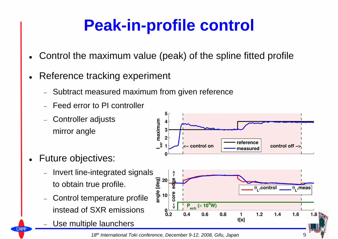
Peak-in-profile control
Control the maximum value (peak) of the spline fitted profile
Reference tracking experiment− Subtract measured maximum from given reference
− Feed error to PI controller
− Controller adjusts mirror angle
Future objectives:− Invert line-integrated signals
to obtain true profile.
− Control temperature profile instead of SXR emissions
− Use multiple launchers

18th International Toki conference, December 9-12, 2008, Gifu, Japan 10
Scenarios with eITBsElectron internal transport barriers created routinely in TCV− High pressure gradients in off-axis region
− confinement improvement 3-6 times TCV L-mode scaling
Created in reversed shear conditions: hollow j profile, reverse shear q profile
In TCV: steady-state eITB plasmas, lasting several current redistribution times.− Low current and density
− Non-inductive:Off-axis ECCD.High bootstrap fraction (>50%)
[Sauter, PRL 2005]
j
off-axis co -ECCD
s tandard j profile
j profile with o ff axis co -ECCD
hollow current profile q
s tandard q profile
q profile with o ff axis co -ECCD
revers e s hear reg ion

18th International Toki conference, December 9-12, 2008, Gifu, Japan 11
Steady-state 100% bootstrap currenteITB generates bootstrap current in high pressure gradient region. The bootstrap current profile must then itself generate the barrier.− Need for high-pressure gradient region and bootstrap current profile to
be precisely and stably aligned.
Experimental results− Heating during Ip ramp-up
− Only EC Heating (perp. to B field)
− Quiescent period lastingseveral current redistribution times (~0.2s)
[S.Coda, IAEA2008]
18th International Toki conference, December 9-12, 2008, Gifu, Japan 12
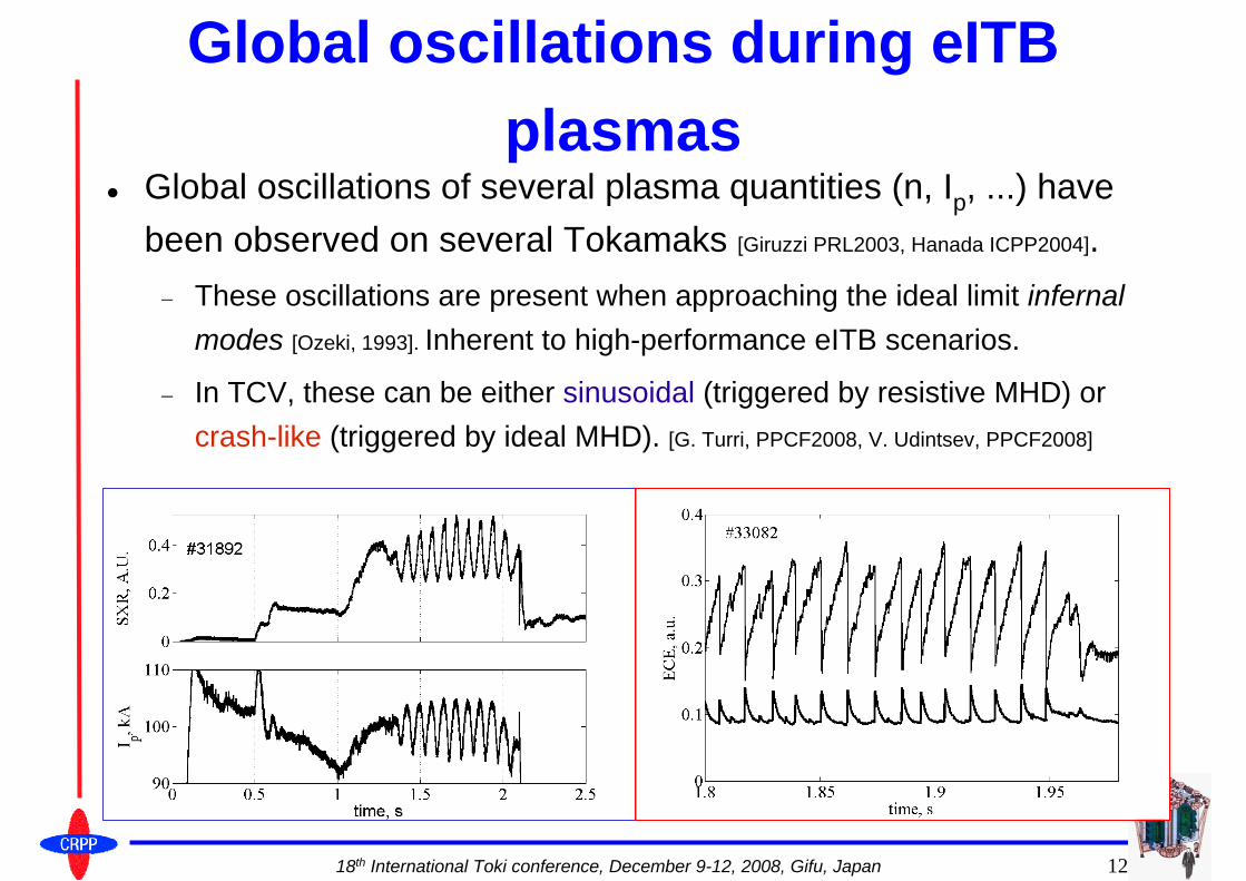
Global oscillations during eITBplasmas
Global oscillations of several plasma quantities (n, Ip, ...) have been observed on several Tokamaks [Giruzzi PRL2003, Hanada ICPP2004].− These oscillations are present when approaching the ideal limit infernal
modes [Ozeki, 1993]. Inherent to high-performance eITB scenarios.
− In TCV, these can be either sinusoidal (triggered by resistive MHD) or crash-like (triggered by ideal MHD). [G. Turri, PPCF2008, V. Udintsev, PPCF2008]

18th International Toki conference, December 9-12, 2008, Gifu, Japan 13
Physical origins of the oscillationsNonlinear coupling between barrier, current profile and MHD
(1)Barrier forms(2)Mode is destabilized(3)Barrier degrades(4)Mode disappears
[G. Turri, PPCF2008]

18th International Toki conference, December 9-12, 2008, Gifu, Japan 14
Current density perturbations -effects on the oscillatory regime
Make current density profile less hollow− Move away from ideal MHD limit
− Barrier strength reduces but oscillations are suppressed.
Experiment: reduce off-axis co-ECCD− current profile becomes
less hollow,
− oscillations stop
− barrier remains
18th International Toki conference, December 9-12, 2008, Gifu, Japan 15
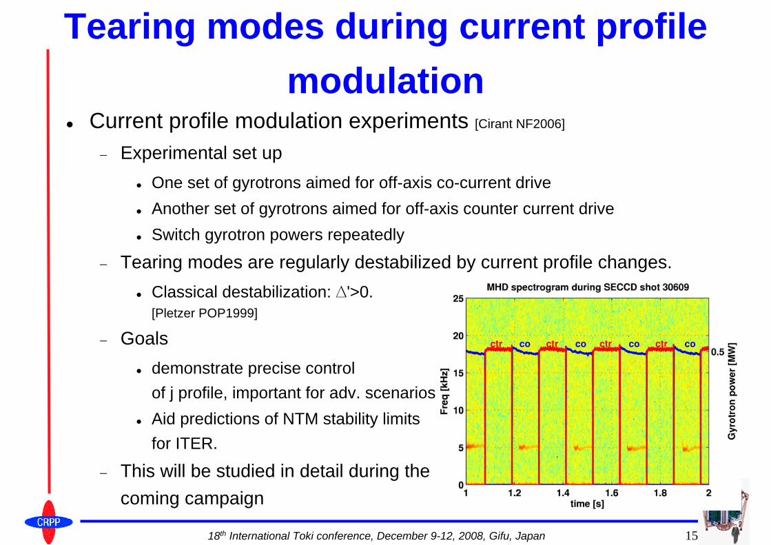
Tearing modes during current profile modulation
Current profile modulation experiments [Cirant NF2006]
− Experimental set upOne set of gyrotrons aimed for off-axis co-current driveAnother set of gyrotrons aimed for off-axis counter current driveSwitch gyrotron powers repeatedly
− Tearing modes are regularly destabilized by current profile changes.Classical destabilization: ∆'>0. [Pletzer POP1999]
− Goalsdemonstrate precise controlof j profile, important for adv. scenariosAid predictions of NTM stability limitsfor ITER.
− This will be studied in detail during the coming campaign

18th International Toki conference, December 9-12, 2008, Gifu, Japan 16
Summary & ConclusionsRecent TCV experiments with ECRH/ECCD− Real-time control
Demonstration of feedback control of sawtooth period by local EC deposition using non-linear controller.Demonstrate of peak-in-profile control by changing EC deposition location.
− Scenarios with internal electron transport barriersSteady-state sustainment using off-axis ECCD.100% bootstrap current in steady-state achieved, no external current drive.Global oscillations, inherent to high performance steady-state scenarios
− Caused by proximity to the infernal mode limit, interplay between barrier and MHD.
− Stabilization by current profile perturbations rendering profile less hollow.
− Localized ECCD deposition effects on tearing stability, aiming at precise control of j profile and NTM stability predictions for ITER.

18th International Toki conference, December 9-12, 2008, Gifu, Japan 17

18th International Toki conference, December 9-12, 2008, Gifu, Japan 18
Reserve slides

18th International Toki conference, December 9-12, 2008, Gifu, Japan 19
Peak-in-profile control (2) Gyrotron power decrease during the shotShot with feedback control recovers maximum by moving deposition off-axisShot with no feedback does not recover.

18th International Toki conference, December 9-12, 2008, Gifu, Japan 20
Stabilization of the oscillatory regimeExample 2: Apply co-current ohmic perturbation− Negligible increase in injected
power
− The perturbation will be peaked on-axis due to better conductivity.
− current profile becomes less hollow
− oscillations stop
− barrier is maintained