Embed Size (px)
Citation preview
Recent Results on the Implementation of a BurstError and Burst Erasure Channel Emulator Using an
FPGA ArchitectureCaterina Travan, Francesca Vatta, and Fulvio Babich
Abstract—The behaviour of a transmission channel may besimulated using the performance abilities of current generationmultiprocessing hardware, namely, a multicore Central Process-ing Unit (CPU), a general purpose Graphics Processing Unit(GPU), or a Field Programmable Gate Array (FPGA). Thesewere investigated by Cullinan et al. in a recent paper (publishedin 2012) where these three devices capabilities were comparedto determine which device would be best suited towards whichspecific task. In particular, it was shown that, for the applicationwhich is objective of our work (i.e., for a transmission channelsimulation), the FPGA is 26.67 times faster than the GPU and10.76 times faster than the CPU. Motivated by these results, inthis paper we propose and present a direct hardware emulation.In particular, a Cyclone II FPGA architecture is implementedto simulate a burst error channel behaviour, in which errorsare clustered together, and a burst erasure channel behaviour, inwhich the erasures are clustered together. The results presentedin the paper are valid for any FPGA architecture that may beconsidered for this scope.
I. INTRODUCTION
In telecommunications, the simulation of the burst errorchannel behaviour is an important topic, given the importanceof the real scenarios in which this channel model may be ap-plied (see next section). This topic has been widely consideredin the recent literature through:
1) CPU implementations using:a) the software tool Matlab [1]: see, e.g., [2], in which
four Matlab programs to simulate the Markovfading channel were developed, and [3], where aburst error correction scheme was implemented;
b) the C/C++ libraries and interface: see, e.g., [4];2) GPU implementations: see, e.g., [5], where the parallel
error-resilient entropy coding (P-EREC) is shown toincrease the resilience of the variable-length coding(VLC) bit-stream to random and burst errors, or [6],
Manuscript received May 2, 2019; revised December 19, 2019. Date ofpublication January 28, 2020. Date of current version January 28, 2020. Theassociate editor prof. Josko Radic has been coordinating the review of thismanuscript and approved it for publication.
Part of this work was presented at the International Conference on Software,Telecommunications and Computer Networks, SOFTCOM ’14, Split, Croatia,September 17-19, 2014.
Caterina Travan is with the TU Graz, Graz University of Technology,Graz, Austria (e-mail: [email protected]). Francesca Vatta andFulvio Babich are with the DIA, University of Trieste, Trieste, Italy (e-mails:[email protected], [email protected]).
Digital Object Identifier (DOI): 10.24138/jcomss.v16i1.766
where a real-time RS decoding is obtained using a GPUdirect transfer;
3) hardware measurement platforms: see, e.g., [7], where asingle-hop network running the point-to-point protocol(PPP) connects a mobile host to a fixed host terminatinga circuit-switched global system for mobile communi-cations (GSM) connection, or [8], where the traces oftraffic are taken from a 2.5 Gb/s interface of a broadbandaccess router of Deutsche Telekom’s internet protocol(IP) platform, connecting residential asymmetric digitalsubscriber line (ADSL) access lines to the backbone;
4) FPGA implementations: see, e.g., [9], where forwarderror correction (FEC) based on Reed-Solomon (RS) co-decoding was implemented on an FPGA, or [10], wherean FPGA implementation of a channel co-decoder, in-terleaver and deinterleaver is presented, considering aMultiple Input and Multiple Output (MIMO) technology.
The simulation of the burst erasure channel – which is alsoimportant given the different real scenarios in which thischannel model may be applied (see next section) – has beenwidely considered as well in the recent literature through:
1) CPU implementations using:a) the software tool Matlab: see, e.g., [11], where
hybrid serial concatenated network codes are pro-posed to contrast burst erasures, and [12], whereerasure-correcting codes are designed for channelswith burst and random erasures;
b) the C/C++ libraries and interface: see, e.g., [4] and[13];
2) GPU implementations: see, e.g., [14], where low-densitygenerator matrix (LDGM) coding is proposed for coun-teracting long loss bursts, or [15], where the speed andaccuracy of the quasi-cyclic low-density parity check(QC-LDPC) simulations are shown to be greatly in-creased by utilising the parallel architecture of GPUs;
3) hardware measurement platforms: see, e.g., [7], whereartificial traces are generated with the same statisticalcharacteristics as actual collected network traces, or [16],where real video and aggregated Internet traces are usedto study the delay per packet in a burst erasure;
4) FPGA implementations: see, e.g., [17], where a designand FPGA implementation of a reconfigurable FECdecoder based on a RS code for WiMax networks ispresented, or [18], where the RS decoder performance
JOURNAL OF COMMUNICATIONS SOFTWARE AND SYSTEMS, VOL. 16, NO. 1, MARCH 2020 19
1845-6421/03/766 © 2020 CCIS
is reviewed as far as its FPGA implementations areconcerned.
As put in evidence by the above presented literatureoverview, the simulation of a transmission channel behaviourmay be implemented using the performance abilities of cur-rent generation multiprocessing hardware, namely, a multicoreCPU, a general purpose GPU, or an FPGA. These wererecently investigated in [19] where these three devices ca-pabilities were compared to determine which device wouldbe best suited towards which specific task. Many benchmarkswere taken into account to compare all three platforms. Inparticular, the Fast Fourier Transform (FFT) benchmark wasinvestigated since it is portable quite easily among all threedevices. The timing differences, reported in Table 1 of [19],show that the GPU is the fastest in processing the FFT. But,if also the transfer times for the GPU to send and receivedata are taken into account, the GPU becomes the slowestof all three platforms. In particular, when considering alsothe transfer time to send and receive data, the FPGA wasshown to be 26.67 times faster than the GPU and 10.76 timesfaster than the CPU. Since in a channel simulation process,not only the signal processing speed is important, but alsoa low latency, i.e., the time between an input and its outputresponse1, which must be as short as possible, in [21] and [22]a hardware emulation has been proposed and implemented,with the objective of potentially accelerating the evaluation ofthe performance characterizing a communication system andthe optimization of its parameters. In particular, inspired bythe above mentioned results of [19] on FPGA speed, and bythose of [10] and [17], all concerning FPGA implementationsinvolving the burst error/erasure channel scenarios, in [22] wasproposed a Cyclone II FPGA architecture implementation tosimulate a burst error channel and a burst erasure channelbehaviour, using the Altera development and education (DE1)board. This choice was driven principally by the resultson FPGA performance speed reported in [19] and by theconsideration that the use of an FPGA architecture allows toreproduce the same hardware environment that may be foundin a real digital communication system.
Afterwards, further results on FPGA implementations, con-cerning the burst error/erasure channel scenarios, came out(reported in the already cited [9] and [18]), and in [20] furthermotivations appeared, with respect to the results of [19], forusing FPGA implementations instead of CPU or GPU ones.In particular, in [20] the advantages and disadvantages ofFPGA implementations were deeply analyzed, showing thatFPGA implementations are to be preferred when low latency,very good connectivity (namely, very high bandwidth) andgood energy efficiency are needed, even if the last propertyis, actually, application dependent. The only disadvantageof an FPGA implementation concerns the engineering costs,
1With an FPGA it is possible to obtain a latency around or below 1microsecond, whereas with a CPU a latency smaller than 50 microsecondsis already very good [20]. Moreover, the latency of an FPGA is much moredeterministic. One of the main reasons for this low latency is that FPGAscan be much more specialized: they do not depend on the generic operatingsystem, and communication does not have to go via generic buses (suchas universal serial bus (USB) or peripheral component interconnect express(PCIe)).
which are typically higher than those afforded to programor configure instruction based architectures (i.e., CPUs andGPUs).
Encouraged by the motivations put in evidence in [20]but also by the growing interest in FPGA implementationsdemonstrated by important companies such as Microsoft, usingFPGAs in its data centers, and Amazon, offering them oncloud services, we decided to go on further, with respect to[22], in analyzing the FPGA implementation therein presented.In particular, in this paper we recall the principal results of[22], giving a more detailed description of the Altera DE1board2 and of the considered scenario, i.e., of the channelmodels and their emulation. Moreover, we give further results,with respect to [22], as far as the duration, in symbols, ofthe error bursts affecting the amplitude of the audio tracksconsidered are concerned. In addition, we give new resultsas far as the amplitude spectra of these audio tracks areconcerned, and also show the amplitude and the root meansquare (RMS) level of the error bursts affecting the amplitudeof the considered audio tracks. Finally, to demonstrate theveracity and accuracy of the advantages, claimed in [20], ofan FPGA implementation with respect to an instruction basedarchitecture implementation, such as a CPU, we consider thecore module used to realize the emulation of the channel, andcompare its FPGA implementation (at disposal on the AlteraDE1 board) with a software implementation of the same mod-ule, showing a great advantage of the FPGA implementationin terms of latency and energy efficiency.
The paper is organized as follows. Section II presents theconsidered scenario and the channel models, and Section IIItheir emulation. In Section IV the implementation of thechosen FPGA architecture is presented. In Section V theobtained results are described and discussed. Finally, SectionVI summarizes the main conclusions.
II. CONSIDERED SCENARIO AND CHANNEL MODELS
In telecommunications, a burst error channel is a datatransmission channel in which errors are grouped together,concentrated in usually short time gaps. The result is that anuninterrupted sequence of bits, called error burst, is affectedby errors. In other words, a burst of length b may be definedas a vector whose non-zero components are grouped togetherin a sequence of length b preceded and followed by at leastone zero component [23].
Examples of error bursts can be found extensively in stor-age mediums. These errors may be the result of a materialdeterioration of the physical storage support, like a scrape ona disc surface, or the lack of oxide, or even the presence ofdust particles, on a magnetic recording tape. Other examplesof error bursts can be found in wireless communications. Inthis case, they may be the result of a temporary reductionin the power of the received signal (fading), leading to ademodulation failure of a certain number of symbols.
A binary erasure channel (BEC) is a natural generalizationof the binary symmetric channel (BSC). The fundamental
2Recently, Intel bought Altera, one of the largest producers of FPGAs,paying $ 16.7 billion, thus making it their largest acquisition ever [20].
20 JOURNAL OF COMMUNICATIONS SOFTWARE AND SYSTEMS, VOL. 16, NO. 1, MARCH 2020

difference is that, in this case, it is assumed that the receivercan also provide the decoder with an additional symbol, inaddition to the characters of the alphabet F2. This symbol,denoted by “?”, corresponds to received values considered apriori not intelligible. To implement this type of receiver, itis sufficient to monitor the quality of the incoming signal anddecide that when this is below an arbitrarily set threshold, thecharacter is to be discarded. In other words, we consider adigital binary transmitter (that can transmit the two values “0”and “1” on a transmission channel). A decoder that implementsthe binary erasure channel can be realized by means of thefunction φ : [0, 1] 7→ {0, 1, ?}.
When such erasures occur in a burst we call this channel aburst erasure channel. In the majority of space communica-tion systems, the data frames are usually protected againstchannel errors using a serial concatenation of a RS outercode followed by a convolutional inner code. When a dataframe is incorrectly decoded it is flagged as incorrect andthus erased from the data stream, giving rise to a flow ofdata including bursts of erasures. Other similar contexts are:deep space communications over noisy channels, where certainpackets are not decodable leaving gaps, or bursts of erasures,in the data stream [24]; free space optical links, where climaticphenomena may preclude photons detection during certaintime intervals [25]; communication scenarios implying the useof on-the-fly changes of code rate, or modulation scheme [26],or also the use of streaming applications (e.g., Internet video,mobile games, etc.). Since, in this case, cyclic redundancycheck (CRC) codes, usually used in this kind of applications,are not sufficient to reduce the delay in the transmissionexperienced by the receiver, the effect produced by this delayis like as if an erasure had occurred [27].
A. Gilbert-Elliott Channel Model
In the early 1960’s, Gilbert [28] and Elliott [29] introduced achannel model, based on a 2-state Markov approach [30], stillextensively employed to statistically characterize the transmis-sion channels through their error patterns description [31] andto analyse the efficiency of channel coding schemes [32].
The model considered a good (G) and bad (B) state gen-erating errors as independent events. The two states G and Bgenerate these error events at a rate 1− k and 1− h, respec-tively. The model is depicted in Fig. 1. When considering,for instance, a burst error channel, the good state can beinterpreted as the state in which a bit is correctly received,whereas the bad state as the state in which a received bit is inerror. When considering, instead, a burst erasure channel, thegood state can be interpreted as the state in which a packet iscorrectly received, whereas the bad state as the state in whicha packet is erased.
Define the transition matrix T as
T =
(1− p pr 1− r
)(1)
with the two transitions probabilities p and r given by
p = P (st = B|st−1 = G) (2)
Fig. 1. Gilbert-Elliott channel model.
r = P (st = G|st−1 = B) (3)
being st the state at time t.Given the stationary state probabilities πG and πB , existing
for p > 0 and r < 1 [8], the error probability PE in the steadystate can be expressed as:
PE = (1− k)πG + (1− h)πB (4)
whereπG =
r
p+ r(5)
πB =p
p+ r(6)
III. CHANNEL EMULATION
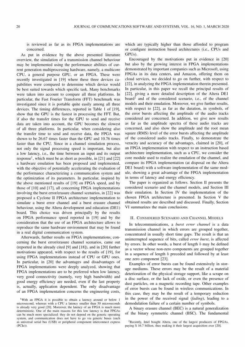
The Altera DE1 board, shown in Fig. 2, includes thefollowing hardware:
• Altera Cyclone II 2C20 FPGA device;• Altera serial configuration device EPCS4;• universal serial bus (USB) blaster (on board) for program-
ming and user application programming interface (API)control supporting both joint test action group (JTAG)and active serial (AS) programming modes;
• 512-Kbyte static random access memory (SRAM);• 8-Mbyte synchronous dynamic random access memory
(SDRAM);• 4-Mbyte flash memory;• secure digital (SD) card socket;• 4 pushbutton switches;• 10 toggle switches;• 10 red user light emitting diodes (LEDs);• 8 green user LEDs;• 50-MHz oscillator, 27-MHz oscillator and 24-MHz oscil-
lator for clock sources;• 24-bit compact disc (CD)-quality audio coder-decoder
(CODEC) with line-in, line-out, and microphone-in jacks;• video graphics array (VGA) digital to analogue converter
(DAC) with VGA-out connector;• electronic industries alliance recommended standard 232
(EIA RS-232) transceiver and 9-pin connector;• personal system/2 (PS/2) mouse/keyboard connector;• 2 40-pin expansion headers with resistor protection.In addition, the DE1 board supports the management via
software of standard input/output (I/O) interfaces and the
C. TRAVAN et al.: RECENT RESULTS ON THE IMPLEMENTATION OF A BURST ERROR AND BURST ERASURE 21
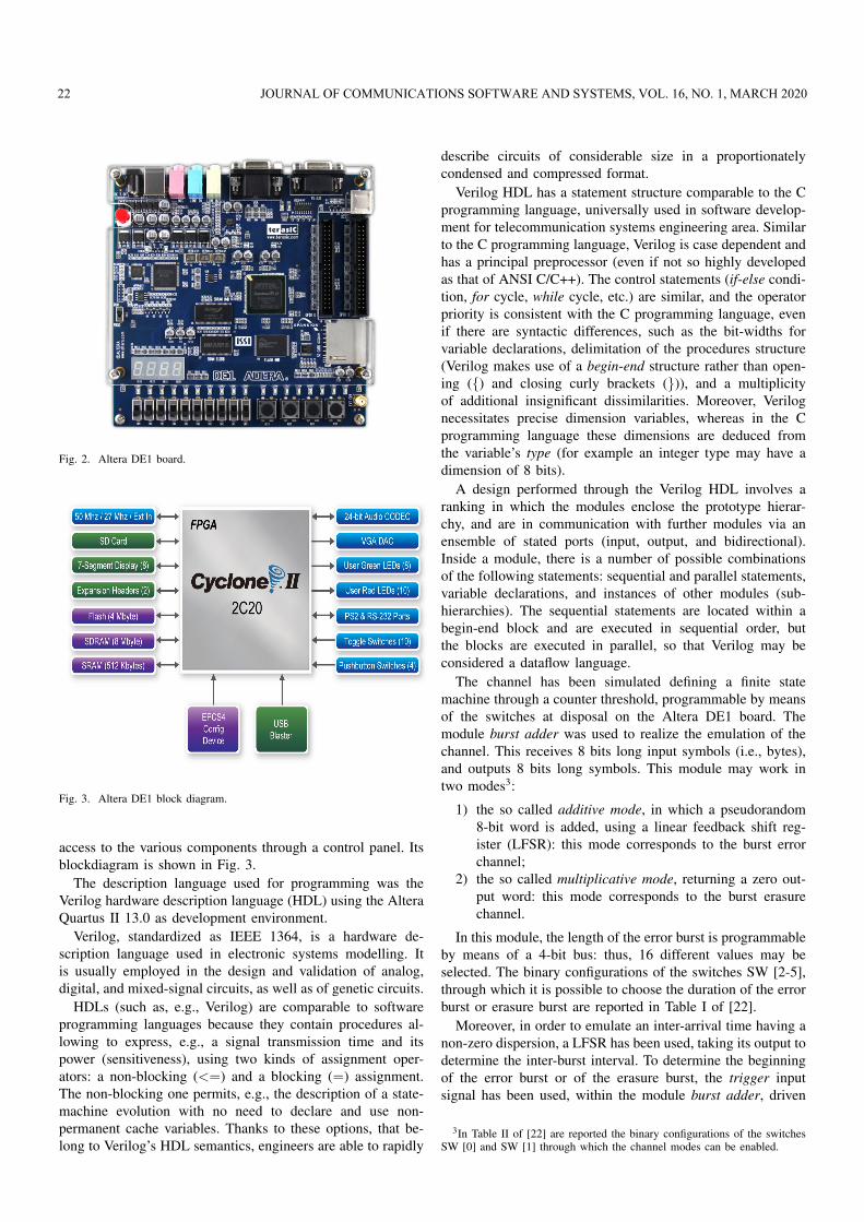
Fig. 2. Altera DE1 board.
Fig. 3. Altera DE1 block diagram.
access to the various components through a control panel. Itsblockdiagram is shown in Fig. 3.
The description language used for programming was theVerilog hardware description language (HDL) using the AlteraQuartus II 13.0 as development environment.
Verilog, standardized as IEEE 1364, is a hardware de-scription language used in electronic systems modelling. Itis usually employed in the design and validation of analog,digital, and mixed-signal circuits, as well as of genetic circuits.
HDLs (such as, e.g., Verilog) are comparable to softwareprogramming languages because they contain procedures al-lowing to express, e.g., a signal transmission time and itspower (sensitiveness), using two kinds of assignment oper-ators: a non-blocking (<=) and a blocking (=) assignment.The non-blocking one permits, e.g., the description of a state-machine evolution with no need to declare and use non-permanent cache variables. Thanks to these options, that be-long to Verilog’s HDL semantics, engineers are able to rapidly
describe circuits of considerable size in a proportionatelycondensed and compressed format.
Verilog HDL has a statement structure comparable to the Cprogramming language, universally used in software develop-ment for telecommunication systems engineering area. Similarto the C programming language, Verilog is case dependent andhas a principal preprocessor (even if not so highly developedas that of ANSI C/C++). The control statements (if-else condi-tion, for cycle, while cycle, etc.) are similar, and the operatorpriority is consistent with the C programming language, evenif there are syntactic differences, such as the bit-widths forvariable declarations, delimitation of the procedures structure(Verilog makes use of a begin-end structure rather than open-ing ({) and closing curly brackets (})), and a multiplicityof additional insignificant dissimilarities. Moreover, Verilognecessitates precise dimension variables, whereas in the Cprogramming language these dimensions are deduced fromthe variable’s type (for example an integer type may have adimension of 8 bits).
A design performed through the Verilog HDL involves aranking in which the modules enclose the prototype hierar-chy, and are in communication with further modules via anensemble of stated ports (input, output, and bidirectional).Inside a module, there is a number of possible combinationsof the following statements: sequential and parallel statements,variable declarations, and instances of other modules (sub-hierarchies). The sequential statements are located within abegin-end block and are executed in sequential order, butthe blocks are executed in parallel, so that Verilog may beconsidered a dataflow language.
The channel has been simulated defining a finite statemachine through a counter threshold, programmable by meansof the switches at disposal on the Altera DE1 board. Themodule burst adder was used to realize the emulation of thechannel. This receives 8 bits long input symbols (i.e., bytes),and outputs 8 bits long symbols. This module may work intwo modes3:
1) the so called additive mode, in which a pseudorandom8-bit word is added, using a linear feedback shift reg-ister (LFSR): this mode corresponds to the burst errorchannel;
2) the so called multiplicative mode, returning a zero out-put word: this mode corresponds to the burst erasurechannel.
In this module, the length of the error burst is programmableby means of a 4-bit bus: thus, 16 different values may beselected. The binary configurations of the switches SW [2-5],through which it is possible to choose the duration of the errorburst or erasure burst are reported in Table I of [22].
Moreover, in order to emulate an inter-arrival time having anon-zero dispersion, a LFSR has been used, taking its output todetermine the inter-burst interval. To determine the beginningof the error burst or of the erasure burst, the trigger inputsignal has been used, within the module burst adder, driven
3In Table II of [22] are reported the binary configurations of the switchesSW [0] and SW [1] through which the channel modes can be enabled.
22 JOURNAL OF COMMUNICATIONS SOFTWARE AND SYSTEMS, VOL. 16, NO. 1, MARCH 2020
FEC encoder
Channel emulator
ADC interface
FIFO FEC
decoder FIFO
DAC interface
Fig. 4. Block scheme of the implemented system.
by the output of one of the two LFSRs. The trigger signal wasused to start the threshold counter.
This emulation corresponds to the Gilbert-Elliott model,described in the previous subsection, with the following pa-rameters:
1) the transition probability from the error-free state (Gin Fig. 1) to the burst/erasure state (B in Fig. 1) isdetermined by the LFSR and is selected as p ≈ 0.5;
2) the permanence in the burst/erasure state (with probabil-ity 1 − r in Fig. 1) is selected to be deterministic, i.e.,r = 0.
The portion of the scheme that emulates the channel isshown in Fig. 1 of [22].
IV. FPGA ARCHITECTURE IMPLEMENTATION
As information source, the output of a programmable audiocodec (Wolfson WM8731) was used (integrated in the AlteraDE1 board).
A. Structure of the Implemented System
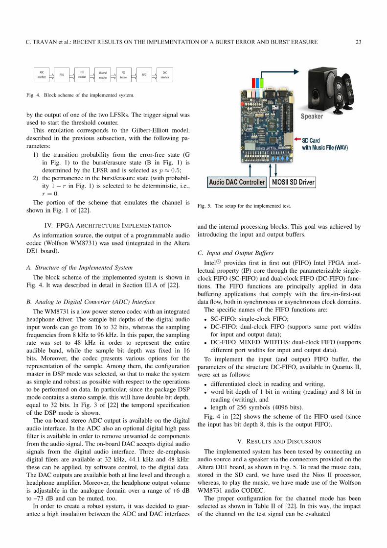
The block scheme of the implemented system is shown inFig. 4. It was described in detail in Section III.A of [22].
B. Analog to Digital Converter (ADC) Interface
The WM8731 is a low power stereo codec with an integratedheadphone driver. The sample bit depths of the digital audioinput words can go from 16 to 32 bits, whereas the samplingfrequencies from 8 kHz to 96 kHz. In this paper, the samplingrate was set to 48 kHz in order to represent the entireaudible band, while the sample bit depth was fixed in 16bits. Moreover, the codec presents various options for therepresentation of the sample. Among them, the configurationmaster in DSP mode was selected, so that to make the systemas simple and robust as possible with respect to the operationsto be performed on data. In particular, since the package DSPmode contains a stereo sample, this will have double bit depth,equal to 32 bits. In Fig. 3 of [22] the temporal specificationof the DSP mode is shown.
The on-board stereo ADC output is available on the digitalaudio interface. In the ADC also an optional digital high passfilter is available in order to remove unwanted dc componentsfrom the audio signal. The on-board DAC accepts digital audiosignals from the digital audio interface. Three de-emphasisdigital filers are available at 32 kHz, 44.1 kHz and 48 kHz:these can be applied, by software control, to the digital data.The DAC outputs are available both at line level and through aheadphone amplifier. Moreover, the headphone output volumeis adjustable in the analogue domain over a range of +6 dBto –73 dB and can be muted, too.
In order to create a robust system, it was decided to guar-antee a high insulation between the ADC and DAC interfaces
Fig. 5. The setup for the implemented test.
and the internal processing blocks. This goal was achieved byintroducing the input and output buffers.
C. Input and Output Buffers
Intel R© provides first in first out (FIFO) Intel FPGA intel-lectual property (IP) core through the parameterizable single-clock FIFO (SC-FIFO) and dual-clock FIFO (DC-FIFO) func-tions. The FIFO functions are principally applied in databuffering applications that comply with the first-in-first-outdata flow, both in synchronous or asynchronous clock domains.
The specific names of the FIFO functions are:• SC-FIFO: single-clock FIFO;• DC-FIFO: dual-clock FIFO (supports same port widths
for input and output data);• DC-FIFO MIXED WIDTHS: dual-clock FIFO (supports
different port widths for input and output data).To implement the input (and output) FIFO buffer, the
parameters of the structure DC-FIFO, available in Quartus II,were set as follows:
• differentiated clock in reading and writing,• word bit depth of 1 bit in writing (reading) and 8 bit in
reading (writing), and• length of 256 symbols (4096 bits).Fig. 4 in [22] shows the scheme of the FIFO used (since
the input has bit depth 8, this is the output FIFO).
V. RESULTS AND DISCUSSION
The implemented system has been tested by connecting anaudio source and a speaker via the connectors provided on theAltera DE1 board, as shown in Fig. 5. To read the music data,stored in the SD card, we have used the Nios II processor,whereas, to play the music, we have made use of the WolfsonWM8731 audio CODEC.
The proper configuration for the channel mode has beenselected as shown in Table II of [22]. In this way, the impactof the channel on the test signal can be evaluated
C. TRAVAN et al.: RECENT RESULTS ON THE IMPLEMENTATION OF A BURST ERROR AND BURST ERASURE 23

1) in the ideal case where, as might be expected, thechannel does not affect the original signal;
2) in the burst error channel case, where the originalsignal is degraded by the superposition of impulse noise,causing a hearing impairment similar to the cracklingpop-corn (in fact, the noise burst in the literature is alsocalled pop-corn noise);
3) in the burst erasure channel case, where an out ofservice, simulated by replacing the symbol to be erasedwith a zero symbol, causes a hearing impairment similarto a sort of crackling in the background.
The duration of the error bursts, that has an evident effecton the disturb affecting the signal, may be varied acting onthe control bus. The perceived disturb is much more evidentin the “burst error” case with respect to the “burst erasure”one.
As part of the system test, a shortened code RS(204,188)4 has been added to the processing chain because, beingRS codes non-binary cyclic error-correcting codes, they arevery advantageous in burst error and burst erasure correction[33]. Moreover, being the use of the RS(204, 188) coderecommended by all DVB standards [34], as such it has beenincluded in many FPGA implementations, like in the alreadycited [9] and [17].
The shortened code RS(204, 188) is obtained from the codeRS(255, 239), limiting to 204 the number of useful bytestransmitted in each packet, while the number of redundancybytes remains 16, maintaining the ability to correct 8 bytes or16, in the case of erasure. In fact, by adding t check symbolsto the data, an RS code can detect any combination of up tot erroneous symbols, or correct up to bt/2c symbols. As anerasure code, it can correct up to t known erasures, or it candetect and correct combinations of errors and erasures [33].Furthermore, RS codes are suitable as multiple-burst bit-errorcorrecting codes, since a sequence of b + 1 consecutive biterrors can affect at most two symbols of size b. Moreover,they have been shown in [24] to be not only a viable but alsoan optimal solution for the burst erasure channel application.
Both the coding block and the decoding one have beenimplemented by providing the appropriate parameters, sum-marized in Table I (rewriting Table III of [22]), to the compilerin the Altera Quartus II environment. Moreover, the ReedSolomon code described above, once added in the processingchain, has been verified to have an error correction capabilitymatching exactly the Reiger’s bound [35].
4The choice of k = 188 was determined by the requirement, considered im-portant at the beginning of the 1990’s, to facilitate the transfer of compressedaudio and video information on radio bridge and satellite communicationssystems, based on the asynchronous transfer mode (ATM) standard. Thissystem, designed for telephone switching and transmission, requires data tobe organized in cells of 53 bytes, of which 48 bytes of data and 5 bytes ofheader. The value of 188 bytes (of which the first 4 constitute the heading)was chosen to facilitate the remapping of the useful data, coded according tothe moving picture experts group (MPEG) standards, in the ATM cells.
TABLE IRS CODE SPECIFICATION FOR DVB STANDARDS
Symbol depth (Bits/Symbol) m = 8
Field Generator polynomial p(x) = x8 + x4 + x3 + x2 + 1
Code Generator polynomial g(x) = (x− α0)(x− α1) · · · (x− α15)
Symbols per block (code length) n = 204
Data symbols (message length) k = 188
Fig. 6. Amplitude of an audio track affected by error bursts of 1 symbol.
A. Objective Measures
In order to obtain objective measures for the channelemulated in Verilog HDL, a LabVIEW program5 has beenimplemented so that to capture the audio signal output fromthe channel and provide a graphical output.
Fig. 7. Amplitude of an audio track affected by error bursts of 15 symbols.
The Virtual Instrument “Compute audio degradation.vi”receives in input 32 audio tracks containing the testing trackaffected by error bursts of duration from 1 to 32 symbols,previously acquired by another VI and saved in a specificfolder. The program allows viewing the amplitude and am-
5LabVIEW is fundamentally a graphical programming language in whichthe user can set up the program to control and cache data. It is called virtualinstrument (VI) because its aspect and working imitate physical instruments,such as oscilloscopes and multimeters. A user interface, or front panel, canbe effortlessly set up, with controls and indicators. Controls are knobs, pushbuttons, dials, and other input mechanisms. Indicators are graphs, LEDs, andother output displays.
24 JOURNAL OF COMMUNICATIONS SOFTWARE AND SYSTEMS, VOL. 16, NO. 1, MARCH 2020

Fig. 8. Amplitude of an audio track affected by error bursts of 30 symbols.
Fig. 9. Spectrum of an audio track affected by error bursts of 1 symbol.
Fig. 10. Spectrum of an audio track affected by error bursts of 15 symbols.
plitude spectrum of each of these tracks and to perform someprocessing on them.
In Figs. 6, 7, and 8 we report, as example, the amplitudeof an audio track affected by error bursts of duration 1, 15,and 30 symbols, respectively, and in Figs. 9, 10, and 11 theirrespective amplitude spectra.
The noise can be extracted and processed, too. In Figs. 12,13, and 14 we report, as example, the amplitude of an errorburst of 1, 15, and 30 symbols duration, respectively. Finally,in Fig. 15 we also report the error RMS level with respect tothe burst length measured in symbols (of 8 bits each).
In Fig. 15 it is shown that the error RMS level tends towards
Fig. 11. Spectrum of an audio track affected by error bursts of 30 symbols.
Fig. 12. Amplitude of an error burst of 1 symbol duration.
Fig. 13. Amplitude of an error burst of 15 symbols duration.
a horizontal asymptote, i.e., towards a constant, as the duration,in symbols, of the error burst increases. In this sense, as faras the amplitudes of the error bursts are concerned (shown inFigs. 12, 13, and 14), we can appreciate a great difference inthe error amplitude comparing Fig. 12, showing the amplitudeof an error burst of 1 symbol duration, with Fig. 13, showingthe amplitude of an error burst of 15 symbols duration, sincethe difference between the respective error RMS levels, shownin Fig. 15, is significant. On the other hand, the differencebetween Fig. 13, showing the amplitude of an error burst of15 symbols duration, and Fig. 14, showing the amplitude of anerror burst of 30 symbols duration, is hard to be appreciated,since the difference between the respective error RMS levels,
C. TRAVAN et al.: RECENT RESULTS ON THE IMPLEMENTATION OF A BURST ERROR AND BURST ERASURE 25
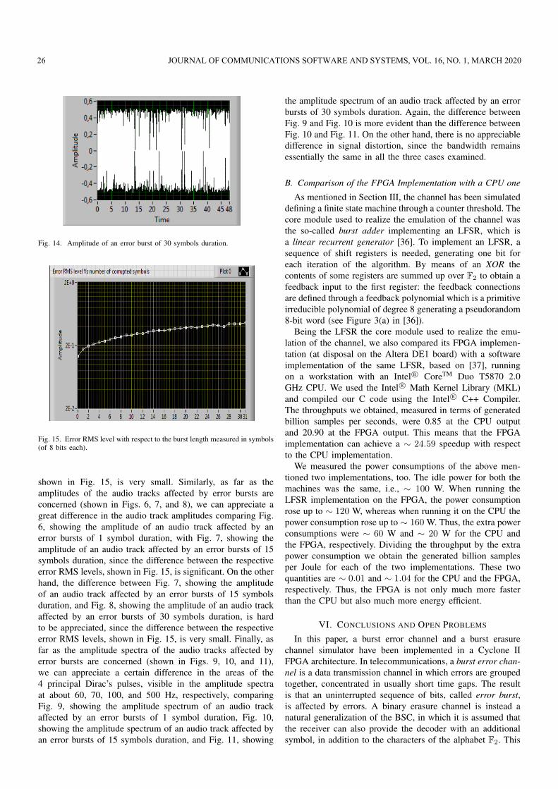
Fig. 14. Amplitude of an error burst of 30 symbols duration.
Fig. 15. Error RMS level with respect to the burst length measured in symbols(of 8 bits each).
shown in Fig. 15, is very small. Similarly, as far as theamplitudes of the audio tracks affected by error bursts areconcerned (shown in Figs. 6, 7, and 8), we can appreciate agreat difference in the audio track amplitudes comparing Fig.6, showing the amplitude of an audio track affected by anerror bursts of 1 symbol duration, with Fig. 7, showing theamplitude of an audio track affected by an error bursts of 15symbols duration, since the difference between the respectiveerror RMS levels, shown in Fig. 15, is significant. On the otherhand, the difference between Fig. 7, showing the amplitudeof an audio track affected by an error bursts of 15 symbolsduration, and Fig. 8, showing the amplitude of an audio trackaffected by an error bursts of 30 symbols duration, is hardto be appreciated, since the difference between the respectiveerror RMS levels, shown in Fig. 15, is very small. Finally, asfar as the amplitude spectra of the audio tracks affected byerror bursts are concerned (shown in Figs. 9, 10, and 11),we can appreciate a certain difference in the areas of the4 principal Dirac’s pulses, visible in the amplitude spectraat about 60, 70, 100, and 500 Hz, respectively, comparingFig. 9, showing the amplitude spectrum of an audio trackaffected by an error bursts of 1 symbol duration, Fig. 10,showing the amplitude spectrum of an audio track affected byan error bursts of 15 symbols duration, and Fig. 11, showing
the amplitude spectrum of an audio track affected by an errorbursts of 30 symbols duration. Again, the difference betweenFig. 9 and Fig. 10 is more evident than the difference betweenFig. 10 and Fig. 11. On the other hand, there is no appreciabledifference in signal distortion, since the bandwidth remainsessentially the same in all the three cases examined.
B. Comparison of the FPGA Implementation with a CPU one
As mentioned in Section III, the channel has been simulateddefining a finite state machine through a counter threshold. Thecore module used to realize the emulation of the channel wasthe so-called burst adder implementing an LFSR, which isa linear recurrent generator [36]. To implement an LFSR, asequence of shift registers is needed, generating one bit foreach iteration of the algorithm. By means of an XOR thecontents of some registers are summed up over F2 to obtain afeedback input to the first register: the feedback connectionsare defined through a feedback polynomial which is a primitiveirreducible polynomial of degree 8 generating a pseudorandom8-bit word (see Figure 3(a) in [36]).
Being the LFSR the core module used to realize the emu-lation of the channel, we also compared its FPGA implemen-tation (at disposal on the Altera DE1 board) with a softwareimplementation of the same LFSR, based on [37], runningon a workstation with an Intel R© CoreTM Duo T5870 2.0GHz CPU. We used the Intel R© Math Kernel Library (MKL)and compiled our C code using the Intel R© C++ Compiler.The throughputs we obtained, measured in terms of generatedbillion samples per seconds, were 0.85 at the CPU outputand 20.90 at the FPGA output. This means that the FPGAimplementation can achieve a ∼ 24.59 speedup with respectto the CPU implementation.
We measured the power consumptions of the above men-tioned two implementations, too. The idle power for both themachines was the same, i.e., ∼ 100 W. When running theLFSR implementation on the FPGA, the power consumptionrose up to ∼ 120 W, whereas when running it on the CPU thepower consumption rose up to ∼ 160 W. Thus, the extra powerconsumptions were ∼ 60 W and ∼ 20 W for the CPU andthe FPGA, respectively. Dividing the throughput by the extrapower consumption we obtain the generated billion samplesper Joule for each of the two implementations. These twoquantities are ∼ 0.01 and ∼ 1.04 for the CPU and the FPGA,respectively. Thus, the FPGA is not only much more fasterthan the CPU but also much more energy efficient.
VI. CONCLUSIONS AND OPEN PROBLEMS
In this paper, a burst error channel and a burst erasurechannel simulator have been implemented in a Cyclone IIFPGA architecture. In telecommunications, a burst error chan-nel is a data transmission channel in which errors are groupedtogether, concentrated in usually short time gaps. The resultis that an uninterrupted sequence of bits, called error burst,is affected by errors. A binary erasure channel is instead anatural generalization of the BSC, in which it is assumed thatthe receiver can also provide the decoder with an additionalsymbol, in addition to the characters of the alphabet F2. This
26 JOURNAL OF COMMUNICATIONS SOFTWARE AND SYSTEMS, VOL. 16, NO. 1, MARCH 2020

symbol corresponds to received values considered a priorinot intelligible, so that to be considered erased. When sucherasures occur in a burst, this channel is called burst erasurechannel.
The software simulation of a transmission channel be-haviour is usually easy to be implemented but also verytime consuming. In particular, the time needed to perform asoftware simulation depends on how complicated is the modelof the channel to be simulated (see, e.g., [38] and [39]) andalso on the bit error rates (BERs) that need to be evaluated(see, e.g., [40] and [41]). Since hardware emulation has theadvantage that the evaluation process occurs in hardware,in place of occurring in the virtual setting of a simulatorimplemented using a standard software, this potentially ac-celerates the evaluation of the performance characterizing acommunication system and the optimization of its parameters.Thus, in this paper a hardware emulation has been proposedand implemented, based on the results of [22]. Furthermore,the fact that a programmable logic FPGA has been chosenis remarkably interesting because it permits the usage of thesame hardware for emulation that is really employed in actualtelecommunications systems.
The implementation suggested for channel emulation isstraightforward and functional and it permits tailoring themodel to a variety of real cases. As a matter of fact, theburst duration may be adjusted operating on the switches,as well as the burst inter-arrival time, which can be tunedsetting the clock driving the LFSR module. In particular, actingon the LFSR polynomial the transition probability from theG to the B state can also be varied. As far as the LFSRmodule in particular is concerned, we also compared its FPGAimplementation (at disposal on the Altera DE1 board) with asoftware implementation of the same LFSR, showing a greatadvantage of the FPGA implementation in terms of latencyand energy efficiency.
After surveying the burst error correcting techniques pre-sented in the literature, a Reed Solomon code was chosen (see,e.g., [42]). This choice has opened on to inspiring results. Inaddition, owing to the employment of an audio signal, it hasbeen feasible to be promptly aware of the advantages emergingfrom this encoding scheme.
Possible future developments may consider the use ofdifferent coding schemes suitable for this application such asiteratively decoded low density parity check (LDPC) codes(see, e.g., [43]-[48]) or related structures, including irregularrepeat-accumulate (IRA) codes [49], generalized IRA codes(see, e.g., [50]), tornado codes and protograph-based codes[26], turbo codes (see, e.g., [51]-[53]), serial and hybridconcatenated codes (see, e.g. [54]-[56]), concatenated turbocodes [57], and product codes (see, e.g., [58]-[60]).
REFERENCES
[1] Matlab: The Language of Technical Computing, Mathworks, Inc.,2012. Available at: http://www.mathworks.co.uk/products/datasheets/pdf/matlab.pdf.
[2] T. Adam and U. Hashim, “Simulation of fading channel and burst errorbehavior of state-3 memoryless Markov model”, Journal of SelectedAreas in Telecommunications (JSAT), Cyber Journals: MultidisciplinaryJournals in Science and Technology, November Edition, 2011, pp. 37-43.
[3] S. Kuchhal, “Simulation of the burst error correction using Matlab”,International Journal of Scientific Research, vol. 2, no. 9, June 2012,pp. 162-165. DOI: 10.15373/22778179/SEP2013/58.
[4] J. A. Briffa and S. Wesemeyer, “SimCommSys: taking the errors outof error-correcting code simulations”, The Journal of Engineering, vol.2014, no. 6, 2014, pp. 332-339. DOI: 10.1049/joe.2014.0055.
[5] Y. Dai, Y. Fang, D. He, and B. Huang, “Parallel design for error-resilient entropy coding algorithm on GPU”, Journal of Parallel andDistributed Computing, vol. 73, no. 4, April 2013, pp. 411-419. DOI:10.1016/j.jpdc.2012.12.008.
[6] T. Suzuki, S.-Y. Kim, J.-I. Kani, T. Hanawa, K.-I. Suzuki, and A. Otaka,“Demonstration of 10-Gbps real-time Reed-Solomon decoding usingGPU direct transfer and kernel scheduling for flexible access systems”,Journal of Lightwave Technology, vol. 36, no. 10, 2018, pp.1875-1881.DOI: 10.1109/JLT.2018.2793938.
[7] A. Konrad, B. Y. Zhao, A. D. Joseph, and R. Ludwig, “A Markov-basedchannel model algorithm for wireless networks”, Wireless Networks, vol.9, no. 3, January 2003, pp. 189-199. DOI: 10.1023/A:1022869025953.
[8] G. Hasslinger and O. Hohlfeld, “The Gilbert-Elliott model for packetloss in real time services on the Internet”, Proceedings of the 14thGI/ITG Conference - Measurement, Modelling and Evalutation of Com-puter and Communication Systems, Dortmund, Germany, March 31 -April 2, 2008, pp. 269-286.
[9] N. Brandonisio, S. Porto, D. Carey, P. Ossieur, G. Talli, N. Parsons, andP. D. Townsend, “Burst-mode FPGA implementation and error locationanalysis of forward error correction for passive optical networks”,Journal of Optical Communications and Networking, vol. 10, no. 4,2018, pp. 298-308. DOI: 10.1364/JOCN.10.000298.
[10] K. Srinandhini and V. Vaithianathan, “FPGA implementation of MIMO-OFDM transceiver”, Proc. of the 2014 International Conference onCommunication and Signal Processing, Melmaruvathur, India, April 3-5,2014, pp. 353-357. DOI: 10.1109/ICCSP.2014.6949861.
[11] R. Bassoli, V. N. Talooki, H. Marques, J. Rodriguez, R. Tafazolli,and S. Mumtaz, “Hybrid serial concatenated network codes for bursterasure channels”, Proc. of the 2015 IEEE 81st Vehicular TechnologyConference (VTC Spring), Glasgow, UK, May 11-14, 2015, pp. 1-4.DOI: 10.1109/VTCSpring.2015.7145864.
[12] M. N. Krishnan and P. V. Kumar, “Rate-optimal streaming codes forchannels with burst and isolated erasures”, Proc. of the 2018 IEEEInternational Symposium on Information Theory (ISIT), Vail, CO, USA,June 17-22, 2018, pp. 1809-1813. DOI: 10.1109/ISIT.2018.8437570.
[13] F. Casu, “Optimization of protection techniques based on FEC codesfor the transmission of multimedia packetized streams”, Ph.D. Disser-tation, Universidad Politecnica de Madrid, Spain, 2017. Available at:http://oa.upm.es/46530/1/FILIPPO CASU.pdf.
[14] M. Kabat, V. David, P. Holub, and M. Pulec, “High-performanceforward error correction: enabling multi-gigabit flows and beyond oncommodity GPU and CPU hardware in presence of packet loss”, FutureGeneration Computer Systems, vol. 54, January 2016, pp. 326-335. DOI:10.1016/j.future.2015.04.007.
[15] A. Wells, “Quasi-cyclic LDPC codes based on balanced incompleteblock designs”, Ph.D. Dissertation, Lancaster University, UK, 2011.
[16] X. Mountrouidou and H. G. Perros, “On the traffic modeling of burstaggregation algorithms using video and data traces”, Telecommunica-tion Systems, vol. 39, no. 3-4, December 2008, pp. 223-234. DOI:10.1007/s11235-008-9127-8.
[17] B. Tiwari and R. Mehra, “Design and implementation of Reed-Solomondecoder for 802.16 network using FPGA”, Proc. of the 2012 IEEEInternational Conference on Signal Processing, Computing and Control,Waknaghat Solan, India, March 15-17, 2012, pp. 1-5. DOI: 10.1109/IS-PCC.2012.6224380.
[18] S. Bakale and D. Dabhade, “Reed-Solomon decoder with parallelsyndrome computation on FPGA: a review”, International Journal ofScience and Research (IJSR), vol. 4, no. 3, March 2015, pp. 1131-1134.
[19] C. R. Cullinan, T. R. Frattesi, and C. M. Wyant, “Com-puting performance benchmarks among CPU, GPU, andFPGA”, Computer Science, 2012, pp. 1-124. Available at:https://web.wpi.edu/Pubs/E-project/Available/E-project-030212-123508/unrestricted/Benchmarking Final.pdf.
[20] A. van der Ploeg, “Why use an FPGA instead of aCPU or GPU?”, Netherlands eScience Center. Available at:https://blog.esciencecenter.nl/why-use-an-fpga-instead-of-a-cpu-or-gpu-b234cd4f309c.
[21] A. Boscolo, F. Vatta, F. Armani, E. Viviani, and D. Salvalaggio,“Physical AWGN channel emulator for bit error rate test of digitalbaseband communication”, Applied Mechanics and Materials, vols. 241-
C. TRAVAN et al.: RECENT RESULTS ON THE IMPLEMENTATION OF A BURST ERROR AND BURST ERASURE 27

244, 2013, pp. 2491-2495. DOI: 10.4028/www.scientific.net/AMM.241-244.2491.
[22] M. Rigo, C. Travan, F. Vatta, and F. Babich, “Implementation of a bursterror and burst erasure channel emulator using an FPGA architecture”,Proc. of the 2014 Int. Conf. on Software, Telecommunications andComputer Networks, SOFTCOM’14, Split, Croatia, September 17-19,2014, pp. 414-418. DOI: 10.1109/SOFTCOM.2014.7039095.
[23] P. K. Das and V. Tyagi, “Codes on s-periodic errors”,Ratio mathematica, vol. 22, 2012, pp. 61-68. Available at:https://pdfs.semanticscholar.org/2140/c9b34056cb3f52a43af2808e0678086d5f18.pdf.
[24] J. Hamkins, “Optimal codes for the burst erasure channel”, Tech Briefs,NASA’s Jet Propulsion Laboratory, Pasadena, California, September2010.
[25] Hamid Hemmati (ed.), Deep-space optical communications, John Wiley& Sons, New York, 2003.
[26] G. P. Calzolari, M. Chiani, F. Chiaraluce, R. Garello, and E. Paolini,“Channel coding for future space missions: new requirements andtrends”, Proceedings of the IEEE, vol. 95, November 2007, pp. 2157-2170. DOI: 10.1109/JPROC.2007.905134.
[27] J.-J. Climent, D. Napp, and V. Requena, “A novel construction forstreaming networks with delays”, Proceedings of the 12th InternationalConference on Computational Intelligence in Security for InformationSystems (CISIS 2019) and 10th International Conference on EUropeanTransnational Education (ICEUTE 2019), Seville, Spain, May 13-15,2019, pp. 185-194. DOI: 10.1007/978-3-030-20005-3 19.
[28] E. Gilbert, “Capacity of a burst-noise channel”, Bell System TechnicalJournal, vol. 39, Sept. 1960, pp. 1253-1265. DOI: 10.1002/j.1538-7305.1960.tb03959.x.
[29] E. O. Elliott, “Estimates of error rates for codes on burst-noise channels”,Bell System Technical Journal, vol. 42, Sept. 1963, pp. 1977-1997. DOI:10.1002/j.1538-7305.1963.tb00955.x.
[30] A. A. Markov, “Theory of algorithms”, Works of the MathematicalInstitute, Academy of Sciences of the USSR, vol. 42, 1954.
[31] B. Girod, K. Stuhlmuller, M. Link, and U. Horn, “Packet loss resilientinternet video streaming”, Proceedings of SPIE Visual Communicationsand Image Processing, San Jose, CA, United States, December 28, 1998,pp. 833-844. DOI: 10.1117/12.334735.
[32] J.-Y. Pyun, J.-J. Shim, S.-J. Ko, and S.-H. Park, “Packet loss re-silience for video stream over the Internet”, IEEE Transactions onConsumer Electronics, vol. 48, no. 3, Aug. 2002, pp. 556-563. DOI:10.1109/TCE.2002.1037041.
[33] G. C. Clark, Jr. and J. B. Cain, Error-correction coding for digitalcommunications, Plenum Press, New York, 1981. DOI: 10.1007/978-1-4899-2174-1 6.
[34] DVB, “Framing structure, channel coding and modulation for digitalterrestrial television”, ETSI EN 300 744, vol. 4.1, January 2001.
[35] S. H. Reiger, “Codes for the correction of ‘clustered’ errors”, IRETransactions on Information Theory, vol. 6, no. 1, March 1960, pp.16-21. DOI: 10.1109/TIT.1960.1057558.
[36] M. Bakiri, C. Guyeux, J. Couchot, and A. Oudjida, “Survey on hardwareimplementation of random number generators on FPGA: theory andexperimental analyses”, Computer Science Review, Elsevier, vol. 27,February 2018, pp.135-153. DOI: 10.1016/j.cosrev.2018.01.002.
[37] R. C. Tausworthe, “Random numbers generated by linear recurrencemodulo two”, Mathematics of Computation, vol. 19, no. 90, 1965, pp.201-209. DOI:10.1090/S0025-5718-1965-0184406-1.
[38] M. Comisso, F. Vatta, G. Buttazzoni, and F. Babich, “3D millimeter-wave peer-to-peer networks with boundary located destination”, IEEECommunications Letters, vol. 23, no. 7, July 2019, pp. 1227-1230. DOI:10.1109/LCOMM.2019.2914650.
[39] M. Comisso, G. Palese, F. Babich, F. Vatta, and G. Buttazzoni, “3Dmulti-beam and null synthesis by phase-only control for 5G antennaarrays”, Electronics (Switzerland), vol. 8, no. 6, June 2019, pp. 1-13.DOI: 10.3390/electronics8060656.
[40] M. Comisso, F. Vatta, G. Buttazzoni, and F. Babich, “Estimation ofthe bit error rate (BER) for uplink millimeter-wave line-of-sight com-munications”, Proc. of the 2019 International Conference on Software,Telecommunications and Computer Networks, Split, Croatia, September19-21, 2019, pp. 1-6. DOI: 10.23919/SOFTCOM.2019.8903692.
[41] A. Soranzo, F. Vatta, M. Comisso, G. Buttazzoni, and F. Babich, “Newvery simply explicitly invertible approximation of the Gaussian Q-function”, Proc. of the 2019 International Conference on Software,Telecommunications and Computer Networks, Split, Croatia, September19-21, 2019, pp. 1-5. DOI: 10.23919/SOFTCOM.2019.8903883.
[42] F. Babich, M. D’Orlando, and F. Vatta, “Distortion estimation algorithmsfor real-time video streaming: an application scenario”, Proc. of the
2011 International Conference on Software, Telecommunications andComputer Networks, Split, Croatia, September 15-17, 2011, pp. 291-295.
[43] F. Babich, M. Noschese, A. Soranzo, and F. Vatta, “Low complexityrate compatible puncturing patterns design for LDPC codes”, Journalof Communication Software and Systems, vol. 14, no. 4, December 2018,pp. 350-358. DOI:10.24138/jcomss.v14i4.639.
[44] F. Vatta, A. Soranzo, M. Comisso, G. Buttazzoni, and F. Babich, “Newexplicitly invertible approximation of the function involved in LDPCcodes density evolution analysis using a Gaussian approximation”,Electronics Letters, vol. 55, no. 22, October 2019, pp. 1183-1186. DOI:10.1049/el.2019.1349.
[45] F. Vatta, F. Babich, F. Ellero, M. Noschese, G. Buttazzoni, and M.Comisso, “Performance study of a class of irregular LDPC codes basedon their weight distribution analysis”, Proc. of the 2019 InternationalConference on Software, Telecommunications and Computer Networks,Split, Croatia, September 19-21, 2019, pp. 1-6. DOI: 10.23919/SOFT-COM.2019.8903633.
[46] F. Vatta, A. Soranzo, M. Comisso, G. Buttazzoni, and F. Babich,“Performance study of a class of irregular LDPC codes throughlow complexity bounds on their belief-propagation decoding thresh-olds”, Proc. of the 111th AEIT International Annual Conference,AEIT 2019, Florence, Italy, September 18-20, 2019, pp. 1-6. DOI:10.23919/AEIT.2019.8893306.
[47] F. Vatta, A. Soranzo, and F. Babich, “More accurate analysis of sum-product decoding of LDPC codes using a Gaussian approximation”,IEEE Communications Letters, vol. 23, no. 2, February 2019, pp. 230-233. DOI: 10.1109/LCOMM.2018.2886261.
[48] F. Vatta, F. Babich, F. Ellero, M. Noschese, G. Buttazzoni, and M.Comisso, “Role of the product λ′(0)ρ′(1) in determining ldpc codeperformance”, Electronics (Switzerland), vol. 8, no. 12, December 2019,pp. 1-14. DOI: 10.3390/electronics8121515.
[49] A. Brown, M. Luby, and A. Shokrollahi, “Repeat-accumulate codes thatapproach the Gilbert-Varshamov bound”, Proc. of the IEEE InternationalSymposium on Information Theory, Adelaide, Australia, September2005, pp. 169-173. DOI: 10.1109/ISIT.2005.1523316.
[50] F. Fagnani and C. Ravazzi, “Spectra and minimum distances ofrepeat multiple accumulate codes”, IEEE Transactions on Informa-tion Theory, vol. 55, no. 11, November 2009, pp. 4905-4924. DOI:10.1109/TIT.2009.2030459.
[51] C. Berrou, A. Glavieux and P. Thitimajshima, “Near Shannonlimit error-correcting coding and decoding: turbo codes”, Proc.of the 1993 IEEE International Conference on Communications- ICC’93, Geneva, Switzerland, May 1993, pp. 1064-1070. DOI:10.1109/ICC.1993.397441.
[52] F. Babich and F. Vatta, “Turbo codes construction for robust hy-brid multitransmission schemes”, Journal of Communication Softwareand Systems, vol. 7, no. 4, December 2011, pp. 128-135. DOI:10.24138/jcomss.v7i4.174.
[53] F. Vatta, R. Romano, and M. T. D. Alizo, “Turbo codes for quantumkey distribution (QKD) applications”, Proc. of the 4th InternationalSymposium on Applied Sciences in Biomedical and CommunicationTechnologies, ISABEL’11, Barcelona, Spain, October 26-29, 2011, pp.1-5. DOI: 10.1145/2093698.2093860.
[54] F. Babich and F. Vatta, “On the error statistics of turbo decod-ing for hybrid concatenated codes design”, Journal of Communica-tion Software and Systems, vol. 15, no. 2, June 2019, pp. 202-212.10.24138/jcomss.v15i2.669.
[55] D. Divsalar and F. Pollara, “Serial and hybrid concatenated codeswith applications”, Proc. of the International Symposium on TurboCodes and Related Topics, Brest, France, Sept. 1997, pp. 80-87. DOI:10.1.1.81.5866.
[56] C. Koller, A. Graell i Amat, J. Kliewer, F. Vatta, K. Sh. Zigangirov,and D. J. Costello, Jr., “Analysis and design of tuned turbo codes”,IEEE Transactions on Information Theory, vol. 58, no. 7, July 2012,pp. 4796-4813. DOI:10.1109/TIT.2012.2195711.
[57] D. J. Costello and G. Meyerhans, “Concatenated turbo codes”, Proc.of the 1996 International Symposium on Information Theory and itsApplications, Victoria B. C., Canada, Sept. 1996.
[58] V. Sidorenko, M. Bossert, and F. Vatta, “Properties and encodingaspects of direct product convolutional codes”, Proc. of the 2012 IEEEInternational Symposium on Information Theory, ISIT’12, Boston, USA,July 1-6, 2012, pp. 2351-2355. DOI: 10.1109/ISIT.2012.6283934.
[59] F. Vatta, V. Sidorenko, and M. Bossert, “Termination and tailbiting ofrate-k/n direct product convolutional codes”, Proc. of the 2010 IEEEInternational Symposium on Information Theory, ISIT’10, Austin, USA,June 13-18, 2010, pp. 2023-2027. DOI: 10.1109/ISIT.2010.5513371.
28 JOURNAL OF COMMUNICATIONS SOFTWARE AND SYSTEMS, VOL. 16, NO. 1, MARCH 2020
[60] B. Liu, Y. Li, B. Rong, L. Gui, and Y. Wu, “LDPC-RS productcodes for digital terrestrial broadcasting transmission system”, IEEETransactions on Broadcasting, vol. 60, no. 1, March 2014, pp. 38-49.DOI: 10.1109/TBC.2013.2291359.
Caterina Travan received her M.Sc. in Electronicsand Telecommunications Engineering from Univer-sity of Trieste, Trieste, Italy, in 2015. She workedthen on her Ph.D. Degree with the Technical Univer-sity of Graz and Infineon Technologies AG, Austria,until 2018, with main focus on novel materials forgas sensing. She is currently employed at InfineonTechnologies AG, Munich, Germany, as develop-ment engineer for environmental sensors.
Francesca Vatta received the M.Sc. Degree in Elec-tronic Engineering and the Ph.D. Degree in Telecom-munications from the University of Trieste, Trieste,Italy, in 1992 and 1998, respectively. She joined theDepartment of Engineering and Architecture (DIA)of the University of Trieste in 1999, where she isAssistant Professor of Information Theory and Error-Control Coding. Starting in 2002, she spent severalmonths as visiting scholar at the University of NotreDame, Notre Dame, IN, U.S.A., cooperating with theCoding Theory Research Group under the guidance
of Prof. D. J. Costello, Jr. Starting in 2005, she spent several months asvisiting scholar at the University of Ulm, Germany, cooperating with theTelecommunications and Applied Information Theory Research Group underthe guidance of Prof. M. Bossert. She is an author of more than 80 paperspublished on international journals and conference proceedings. Her currentresearch interests are in the area of channel coding concerning, in particular,the analysis and design of capacity achieving coding schemes.
Fulvio Babich received the doctoral degree, (Lau-rea), cum laude, in Electrical Engineering, at theUniversity of Trieste, on July 1984. After grad-uation he was with Telettra at the Research andDevelopment Laboratories, where he was engagedin optical fiber communications. Then he joinedZeltron, where he was a communication systemengineer, responsible of the activities within theESPRIT program. In 1992 he joined the Departmentof Electrical Engineering (DEEI) of the Universityof Trieste, where he is Professor of Signals and Sys-
tems and Wireless Networks. Fulvio Babich is vice director of Department ofEngineering and Architecture. He is the coordinator of the Ph.D. in Industrialand Information Engineering of the University of Trieste. His current researchinterests are in the field of wireless networks and personal communications.He is involved in channel modeling, multiple access techniques, channelencoding, error control techniques and cross-layer design. Fulvio Babichserves as reviewer for many international journals, has served as co-chairfor the Communication Theory Symposium, ICC 2005, Seul, ICC 2014,Sydney, and ICC 2017, Paris, for the Wireless Communication Symposium,ICC 2011, Kyoto, and for the Wireless Communication Symposium, WCSP2012, Huangshan, China. He has served as General chair of the 13th IEEEIFIP Annual Mediterranean Ad Hoc Networking Workshop, Med-Hoc-Net2014 June 2-4, 2014 Piran, Slovenia. Fulvio Babich is Senior Member ofIEEE.
C. TRAVAN et al.: RECENT RESULTS ON THE IMPLEMENTATION OF A BURST ERROR AND BURST ERASURE 29