Embed Size (px)
Citation preview
23
Recent Technology Development and Manufacturing Experiences of Clad Steel Pipe
for Natural Gas Transportation Pipelines
Kenta Nishimoto* Taiki Aizawa* Shin Takimoto** Wataru Kawakami**
Recent Technology Development and Manufacturing Experiences of Clad Steel Pipe for Natural Gas Transportation Pipelines
JSW supplied clad steel pipe to major oil and gas producer in 1987. We has been developing, such as JSW-65R steel in order to respond to the demand of high strength and high toughness and X70 Grade clad steel pipe in order to differentiate from the competition. Toughness controlling factors of the clad steel pipe base material is being clarified by the detailed analysis of the microstructure and fracture surface. Recently, we have been also working on the development of welding equipment and technology in order to improve productivity and respond to a variety of lineup of clad steel pipe of small diameter thick-walled. This paper reports the technology development trend and manufacturing performance of clad steel pipe.
-Synopsis-
1. Introduction
Natural gas that vast of reserves are distributed all over the world, have been expected that the demand will continuously increase in the future, with its feature of lower emissions of carbon dioxide and sulfur oxides than other type of fossil fuel. Natural gas mined from gas field is high corrosive gas (sour gas) that contain methane as the main component and many impurities such as moisture, sulfur compounds, chlorine compounds and carbon dioxide, and those impurities need to be removed at pre-treatment facilities. Therefore, high corrosion resistance is required for linepipe that is used for gas transportation from wellhead to pre-treatment facilities. Clad products are composite materials combining various alloys with steel, and have a range of special characteristics not found in regular steel. These products typically feature the combination of carbon steel or low-alloy steel to ensure strength with stainless steel or high-alloy steel to add corrosion resistance. Clad steel pipe is highly acclaimed for its excellent cost-effectiveness and corrosion resistance for sour gas service, and JSW has supplied longitudinal welded clad steel pipe to all over the world.
In recent years, Charpy impact toughness specification temperature for backing steel of clad steel pipe have been lowered, since increasing safety requirements for natural gas transportation.
Also, to reduce the total amount of material and then the whole project cost, it is expected that the demand of pipes that have higher mechanical properties will be increasing. Based on these circumstances, JSW have developed X65 (named JSW-65R) and X70 Grade backing steel material for clad steel pipe, corresponding the requirement of low temperature toughness at -40 ̊ C. In addition, JSW have carried out technical improvements and facility introductions, to gain productivity and to produce a variety of pipe sizes, and especially to expand the lineup of high wall thickness small diameter clad steel pipe. This report describes history of technology, latest trend of technical development and supply records about JSW’s clad steel pipe.
2. Manufacturing Method of Clad Steel Pipe
2.1 Manufacturing Method of Clad Steel PlateAs manufacturing method of clad steel plate,
there are some methods such as hot rolling method, explosion method and weld overlay method. Especially among them, JSW applies hot rolling method that is the most economical and suitable for commercial production process of thin and large size clad steel plate required for clad steel pipe application. Figure 1 shows manufacturing process of hot rolled clad steel plate. The surface of Carbon
*Muroran Research Laboratory **Muroran Plant

JSW TECHNICAL REVIEW No.20
Figure 1 Manufacturing sequence of clad steel plate
Figure 2 Manufacturing sequence of clad steel pipe
24
Recent Technology Development and Manufacturing Experiences of Clad Steel Pipe for Natural Gas Transportation Pipelines
steel base metal and Corrosion Resistance Alloy (hereinafter called “CRA”) is firstly prepared to be smooth and clean condition. After assembly by welding together, they are heated up to more than 1000 ˚C in the furnace then rolled. High bonding strength between base metal and CRA is obtained during this hot rolling operation by diffusion bonding process. Ni plating is performed in advance to the CRA surface to reduce residual stress and improve the bonding strength. This clad plate is then water quenched and tempered in order to satisfy both mechanical properties of base metal and corrosion properties of CRA. Non-destructive examination and mechanical testing is carried out to confirm the soundness of the clad plate. After cleaning, this clad plate is provided for the fabrication of clad steel pipe.
2.2 Manufacturing Method of Clad Steel PipeJSW has produced longitudinal welded clad
steel pipe using press bending method that have flexibility for pipe manufacturing of various
diameter and wall thickness. Standard manufacturing range is minimum of 8” to maximum of 36”, in diameter. Figure 2 shows standard manufacturing sequence of clad steel pipe. Clad steel pipe is manufactured using clad steel plate made by hot rolled clad steel plate shown in Figure 1 above. After machining of longitudinal weld bevel, plate is cold formed by press to pipe shape. For inner side of the longitudinal welding, high-efficiency welding with a small number of passes is applied using the welding material made of stainless steel or high alloy which has equal to or superior corrosion resistance to cladding material. Furthermore, as the strength member of the pipe, mechanical properties equivalent to its base metal and good weldability are required for carbon steel portion of the longitudinal weld seam. After longitudinal welding, hydrostatic test and specified non-destructive examinations are carried out to each clad pipe, and then the clad steel pipe is ready for shipment.
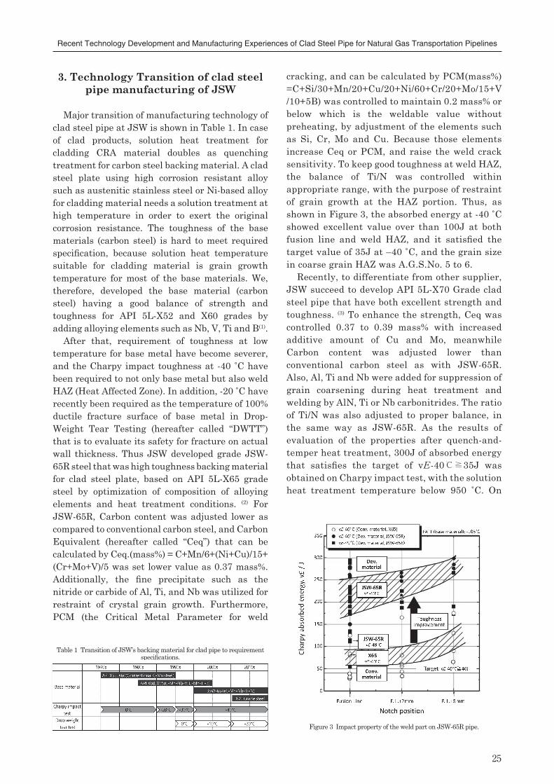
Figure 3 Impact property of the weld part on JSW-65R pipe.
Table 1 Transition of JSW’s backing material for clad pipe to requirement specifications.
25
Recent Technology Development and Manufacturing Experiences of Clad Steel Pipe for Natural Gas Transportation Pipelines
3. Technology Transition of clad steel pipe manufacturing of JSW
Major transition of manufacturing technology of clad steel pipe at JSW is shown in Table 1. In case of clad products, solution heat treatment for cladding CRA material doubles as quenching treatment for carbon steel backing material. A clad steel plate using high corrosion resistant alloy such as austenitic stainless steel or Ni-based alloy for cladding material needs a solution treatment at high temperature in order to exert the original corrosion resistance. The toughness of the base materials (carbon steel) is hard to meet required specification, because solution heat temperature suitable for cladding material is grain growth temperature for most of the base materials. We, therefore, developed the base material (carbon steel) having a good balance of strength and toughness for API 5L-X52 and X60 grades by adding alloying elements such as Nb, V, Ti and B(1).
After that, requirement of toughness at low temperature for base metal have become severer, and the Charpy impact toughness at -40 ˚C have been required to not only base metal but also weld HAZ (Heat Affected Zone). In addition, -20 ˚C have recently been required as the temperature of 100% ductile fracture surface of base metal in Drop-Weight Tear Testing (hereafter called “DWTT”) that is to evaluate its safety for fracture on actual wall thickness. Thus JSW developed grade JSW-65R steel that was high toughness backing material for clad steel plate, based on API 5L-X65 grade steel by optimization of composition of alloying elements and heat treatment conditions. (2) For JSW-65R, Carbon content was adjusted lower as compared to conventional carbon steel, and Carbon Equivalent (hereafter called “Ceq”) that can be calculated by Ceq.(mass%) = C+Mn/6+(Ni+Cu)/15+ (Cr+Mo+V)/5 was set lower value as 0.37 mass%. Additionally, the fine precipitate such as the nitride or carbide of Al, Ti, and Nb was utilized for restraint of crystal grain growth. Furthermore, PCM (the Critical Metal Parameter for weld
cracking, and can be calculated by PCM(mass%)=C+Si/30+Mn/20+Cu/20+Ni/60+Cr/20+Mo/15+V/10+5B) was controlled to maintain 0.2 mass% or below which is the weldable value without preheating, by adjustment of the elements such as Si, Cr, Mo and Cu. Because those elements increase Ceq or PCM, and raise the weld crack sensitivity. To keep good toughness at weld HAZ, the balance of Ti/N was controlled within appropriate range, with the purpose of restraint of grain growth at the HAZ portion. Thus, as shown in Figure 3, the absorbed energy at -40 ˚C showed excellent value over than 100J at both fusion line and weld HAZ, and it satisfied the target value of 35J at –40 ˚C, and the grain size in coarse grain HAZ was A.G.S.No. 5 to 6.
Recently, to differentiate from other supplier, JSW succeed to develop API 5L-X70 Grade clad steel pipe that have both excellent strength and toughness. (3) To enhance the strength, Ceq was controlled 0.37 to 0.39 mass% with increased additive amount of Cu and Mo, meanwhile Carbon content was adjusted lower than conventional carbon steel as with JSW-65R. Also, Al, Ti and Nb were added for suppression of grain coarsening during heat treatment and welding by AlN, Ti or Nb carbonitrides. The ratio of Ti/N was also adjusted to proper balance, in the same way as JSW-65R. As the results of evaluation of the properties after quench-and-temper heat treatment, 300J of absorbed energy that satisfies the target of vE-40℃≧35J was obtained on Charpy impact test, with the solution heat treatment temperature below 950 ˚C. On
JSW TECHNICAL REVIEW No.20
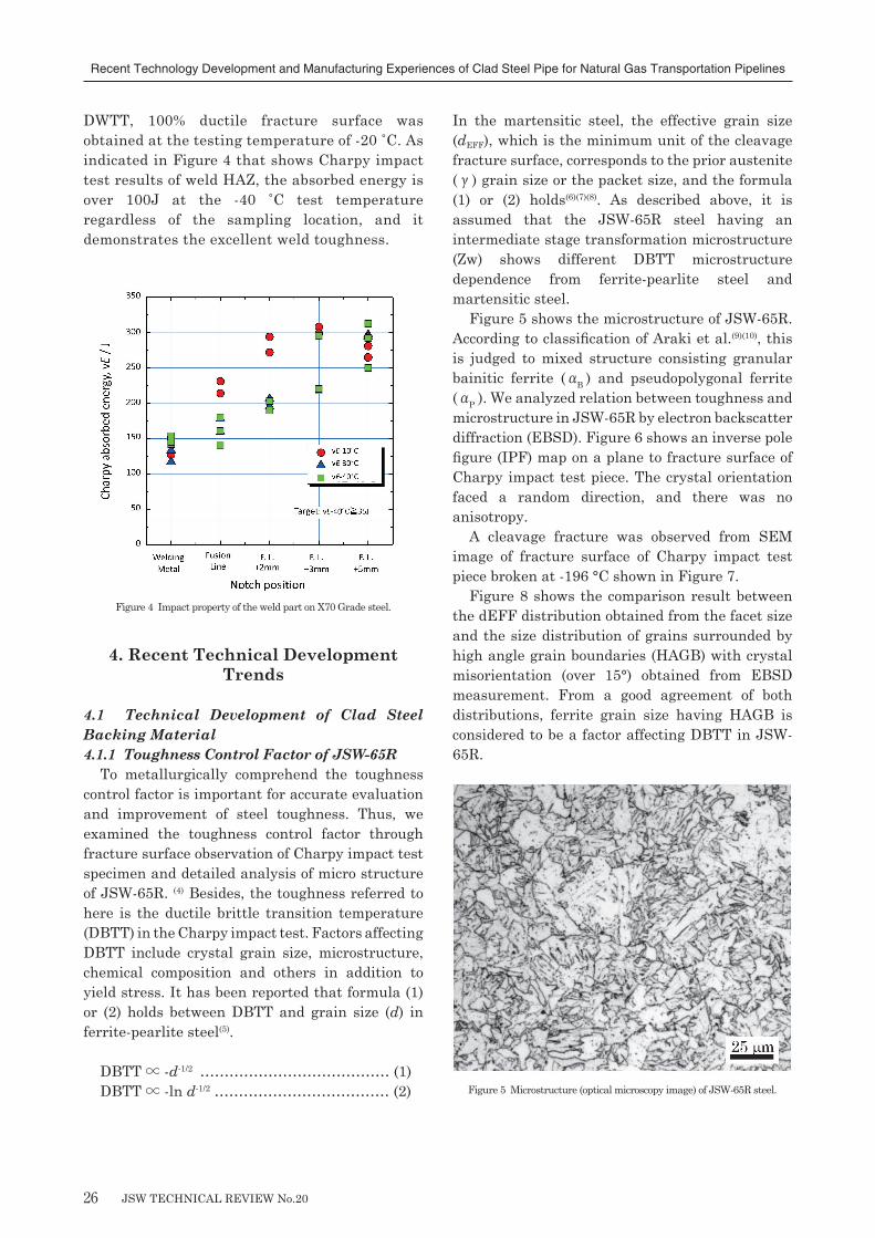
Figure 4 Impact property of the weld part on X70 Grade steel.
Figure 5 Microstructure (optical microscopy image) of JSW-65R steel.
26
Recent Technology Development and Manufacturing Experiences of Clad Steel Pipe for Natural Gas Transportation Pipelines
DWTT, 100% ductile fracture surface was obtained at the testing temperature of -20 ˚C. As indicated in Figure 4 that shows Charpy impact test results of weld HAZ, the absorbed energy is over 100J at the -40 ˚C test temperature regardless of the sampling location, and it demonstrates the excellent weld toughness.
4. Recent Technical Development Trends
4.1 Technical Development of Clad Steel Backing Material4.1.1 Toughness Control Factor of JSW-65R
To metallurgically comprehend the toughness control factor is important for accurate evaluation and improvement of steel toughness. Thus, we examined the toughness control factor through fracture surface observation of Charpy impact test specimen and detailed analysis of micro structure of JSW-65R. (4) Besides, the toughness referred to here is the ductile brittle transition temperature (DBTT) in the Charpy impact test. Factors affecting DBTT include crystal grain size, microstructure, chemical composition and others in addition to yield stress. It has been reported that formula (1) or (2) holds between DBTT and grain size (d) in ferrite-pearlite steel(5).
DBTT ∝ -d-1/2 ………………………………… (1)DBTT ∝ -ln d-1/2 ……………………………… (2)
In the martensitic steel, the effective grain size (dEFF), which is the minimum unit of the cleavage fracture surface, corresponds to the prior austenite (γ) grain size or the packet size, and the formula (1) or (2) holds(6)(7)(8). As described above, it is assumed that the JSW-65R steel having an intermediate stage transformation microstructure (Zw) shows different DBTT microstructure dependence from ferrite-pearlite steel and martensitic steel.
Figure 5 shows the microstructure of JSW-65R. According to classification of Araki et al.(9)(10), this is judged to mixed structure consisting granular bainitic ferrite (αB ) and pseudopolygonal ferrite (αP ). We analyzed relation between toughness and microstructure in JSW-65R by electron backscatter diffraction (EBSD). Figure 6 shows an inverse pole figure (IPF) map on a plane to fracture surface of Charpy impact test piece. The crystal orientation faced a random direction, and there was no anisotropy.
A cleavage fracture was observed from SEM image of fracture surface of Charpy impact test piece broken at -196 °C shown in Figure 7.
Figure 8 shows the comparison result between the dEFF distribution obtained from the facet size and the size distribution of grains surrounded by high angle grain boundaries (HAGB) with crystal misorientation (over 15°) obtained from EBSD measurement. From a good agreement of both distributions, ferrite grain size having HAGB is considered to be a factor affecting DBTT in JSW-65R.
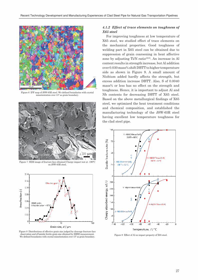
Figure 6 IPF map of JSW-65R steel. We defined boundaries with crystal misorientation over 15° as grain boundary.
Figure 7 SEM image of fracture face obtained Charpy impact test at -196°C on JSW-65R steel.
Figure 8 Distributions of effective grain size judged by cleavage fracture face observation and of bainitic ferrite grain size obtained by EBSD measurement.We defined boundaries with crystal misorientation over 15° as grain boundary.
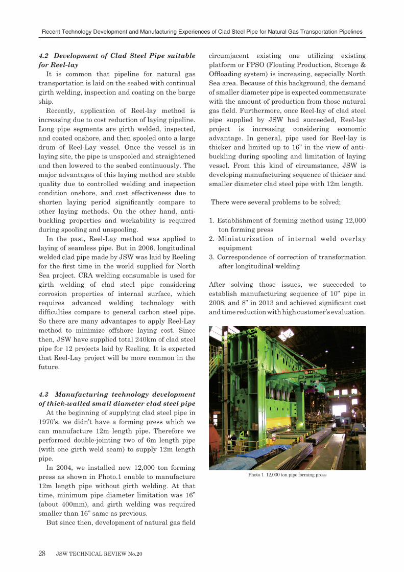
Figure 9 Effect of Al on impact property of X65 steel.
27
Recent Technology Development and Manufacturing Experiences of Clad Steel Pipe for Natural Gas Transportation Pipelines
4.1.2Effect of trace elements on toughness of X65 steel
For improving toughness at low temperature of X65 steel, we studied effect of trace elements on the mechanical properties. Good toughness of welding part in X65 steel can be obtained due to suppression of grain coarsening in heat affective zone by adjusting Ti/N ratio(2)(3). An increase in Al content results in strength increase, but Al addition over 0.030 mass% shift DBTT to higher temperature side as shown in Figure 9. A small amount of Niobium added hardly affects the strength, but excess addition increase DBTT. Also, S of 0.0040 mass% or less has no effect on the strength and toughness. Hence, it is important to adjust Al and Nb contents for decreasing DBTT of X65 steel. Based on the above metallurgical findings of X65 steel, we optimized the heat treatment conditions and chemical composition, and established the manufacturing technology of the JSW-65R steel having excellent low temperature toughness for the clad steel pipe.
JSW TECHNICAL REVIEW No.20
Photo 1 12,000 ton pipe forming press
28
Recent Technology Development and Manufacturing Experiences of Clad Steel Pipe for Natural Gas Transportation Pipelines
4.2 Development of Clad Steel Pipe suitable for Reel-lay
It is common that pipeline for natural gas transportation is laid on the seabed with continual girth welding, inspection and coating on the barge ship.
Recently, application of Reel-lay method is increasing due to cost reduction of laying pipeline. Long pipe segments are girth welded, inspected, and coated onshore, and then spooled onto a large drum of Reel-Lay vessel. Once the vessel is in laying site, the pipe is unspooled and straightened and then lowered to the seabed continuously. The major advantages of this laying method are stable quality due to controlled welding and inspection condition onshore, and cost effectiveness due to shorten laying period significantly compare to other laying methods. On the other hand, anti-buckling properties and workability is required during spooling and unspooling.
In the past, Reel-Lay method was applied to laying of seamless pipe. But in 2006, longitudinal welded clad pipe made by JSW was laid by Reeling for the first time in the world supplied for North Sea project. CRA welding consumable is used for girth welding of clad steel pipe considering corrosion properties of internal surface, which requires advanced welding technology with difficulties compare to general carbon steel pipe. So there are many advantages to apply Reel-Lay method to minimize offshore laying cost. Since then, JSW have supplied total 240km of clad steel pipe for 12 projects laid by Reeling. It is expected that Reel-Lay project will be more common in the future.
4.3 Manufacturing technology development of thick-walled small diameter clad steel pipe
At the beginning of supplying clad steel pipe in 1970’s, we didn’t have a forming press which we can manufacture 12m length pipe. Therefore we performed double-jointing two of 6m length pipe (with one girth weld seam) to supply 12m length pipe.
In 2004, we installed new 12,000 ton forming press as shown in Photo.1 enable to manufacture 12m length pipe without girth welding. At that time, minimum pipe diameter limitation was 16” (about 400mm), and girth welding was required smaller than 16” same as previous.
But since then, development of natural gas field
circumjacent existing one utilizing existing platform or FPSO (Floating Production, Storage & Offloading system) is increasing, especially North Sea area. Because of this background, the demand of smaller diameter pipe is expected commensurate with the amount of production from those natural gas field. Furthermore, once Reel-lay of clad steel pipe supplied by JSW had succeeded, Reel-lay project is increasing considering economic advantage. In general, pipe used for Reel-lay is thicker and limited up to 16” in the view of anti-buckling during spooling and limitation of laying vessel. From this kind of circumstance, JSW is developing manufacturing sequence of thicker and smaller diameter clad steel pipe with 12m length.
There were several problems to be solved;
1. Establishment of forming method using 12,000 ton forming press
2. Miniaturization of internal weld overlay equipment
3. Correspondence of correction of transformation after longitudinal welding
After solving those issues, we succeeded to establish manufacturing sequence of 10” pipe in 2008, and 8” in 2013 and achieved significant cost and time reduction with high customer’s evaluation.
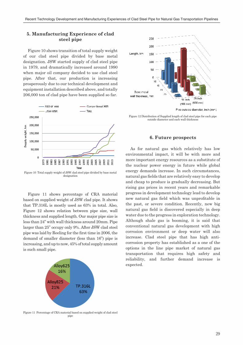
Figure 10 Total supply weight of JSW clad steel pipe divided by base metal designation
Figure 12 Distribution of Supplied length of clad steel pipe for each pipe outside diameter and each wall thickness
Figure 11 Percentage of CRA material based on supplied weight of clad steel pipe
29
Recent Technology Development and Manufacturing Experiences of Clad Steel Pipe for Natural Gas Transportation Pipelines
5. Manufacturing Experience of clad steel pipe
Figure 10 shows transition of total supply weight of our clad steel pipe divided by base metal designation. JSW started supply of clad steel pipe in 1979, and dramatically increased around 1990 when major oil company decided to use clad steel pipe. After that, our production is increasing prosperously due to our technical development and equipment installation described above, and totally 206,000 ton of clad pipe have been supplied so far.
Figure 11 shows percentage of CRA material based on supplied weight of JSW clad pipe. It shows that TP.316L is mostly used as 63% in total. Also, Figure 12 shows relation between pipe size, wall thickness and supplied length. Our major pipe size is less than 24” with wall thickness around 20mm. Pipe larger than 25” occupy only 9%. After JSW clad steel pipe was laid by Reeling for the first time in 2006, the demand of smaller diameter (less than 16”) pipe is increasing, and up to now, 45% of total supply amount is such small pipe.
6.Future prospects
As for natural gas which relatively has low environmental impact, it will be with more and more important energy resources as a substitute of the nuclear power energy in future while global energy demands increase. In such circumstances, natural gas fields that are relatively easy to develop and cheap to produce is gradually decreasing. But rising gas prices in recent years and remarkable progress in development technology lead to develop new natural gas field which was unprofitable in the past, or severe condition. Recently, new big natural gas field is discovered especially in deep water due to the progress in exploration technology. Although shale gas is booming, it is said that conventional natural gas development with high corrosion environment or deep water will also increase. Clad steel pipe that has high anti-corrosion property has established as a one of the options in the line pipe market of natural gas transportation that requires high safety and reliability, and further demand increase is expected.

JSW TECHNICAL REVIEW No.2030
Recent Technology Development and Manufacturing Experiences of Clad Steel Pipe for Natural Gas Transportation Pipelines
7. Conclusion
(1)Corresponding to the severe requirement of toughness at low temperature for base metal, JSW developed JSW-65R steel and API 5L-X70 Grade base metal with high toughness at both base metal and HAZ position using AlN, Ti or Nb carbonitrides to suppress grain coarsening during heat treatment and welding.
(2)As for the JSW-65R steel having an intermediate stage transformation microstructure (Zw), ferrite grain size having high angle grain boundaries (HAGB) with crystal misorientation (over 15°) is considered to be a factor affecting the ductile brittle transition temperature (DBTT). And to obtain good toughness, proper adjustment of Ti/N is required in addition to adjustment of Al and Nb contents.
(3)As results of establishment of forming method, miniaturization of internal weld overlay equipment and correspondence of correction of transformation after longitudinal welding, fabrication sequence of 8” heavy wall clad steel pipe has been established suitable for Reel-lay of clad steel pipe.
(4)Since supply of clad steel pipe in 1987, totally 206,000 ton of clad pipe have been supplied so far. Recently, demand of small diameter clad steel pipe suitable for Reel-lay is tend to increase, and expected to apply for development of deep water natural gas field in the future.
This paper reports development of base metal for clad steel pipe such as JSW-65R steel, research of toughness affecting factor, establishment of manufacturing technology of small heavy wall clad steel pipe and supply experience of clad steel pipe. To satisfy customer’s requirement that changes day by day, JSW will expand our efforts to improve quality and productivity.
References
(1) T.Fukuda, Y.Fukami, K.Sekimura, T.Nakata and Y.Saitoh, The Japan Steel Works Technology Review, No.47 (1988)pp.47-53 (in Japanese)
(2) R.Kayano, Y.Nitta, H.Gomi, M.Sakuraba : The Japan Steel Works, Ltd. Technical Report, Vol.55(2004)p.79-87 (in Japanese)
(3) S.Sato, R.Kayano, Y.Nitta, H.Gomi, M.Sakuraba, W.Kawakami, T.Maruya : The Japan Steel Works, Ltd. Technical Report, Vol.60(2009)p.41-47 (in Japanese)
(4) Y.Izumiyama, R.Kayano : The Japan Steel Works, Ltd. Technical Report, Vol.64(2013)p.15-21 (in Japanese)
(5) N. J. Petch: Philos. Mag., Vol. 3 (1958), p.1089(6) T. Inoue, S. Matsuda, Y. Okamura and K. Aoki:
Trans. JIM, Vol. 11 (1970), p.36(7) F. Terasaki and H. Ohtani: Trans. Iron Steel
Inst. Jpn., Vol. 12 (1972), p.45(8) H.Ohtani, F.Terasaki, T.Kunitake : TETSU-TO-
HAGANE, Vol.58(1972),p.434 (in Japanese)(9) T.Araki, M. Enomoto, K. Shibata: Tetsu-to-
Hagané, Vol. 77 (1991), p.1544 (in Japanese)(10)Atlas for bainitic microstructures. Vol. 1. :
continuous-cooled zw microstructures of low carbon steels, The Iron and Steel Institute of Japan, (1992), p.1 (in Japanese)