Embed Size (px)
Citation preview
International Journal of Electrical and Electronics
Engineering Research (IJEEER)
ISSN(P): 2250-155X; ISSN(E): 2278-943X
Vol. 3, Issue 5, Dec 2013, 65-76
© TJPRC Pvt. Ltd.
RECENT TRENDS IN CONDITION ASSESSMENT OF INDUCTION MOTOR DRIVES
U. MOHAN RAO & D. V. KUMAR
Department of Electrical and Electronics Engineering, Aditya Institute of Technology and Management,
Andhra Pradesh, India
ABSTRACT
The present paper highlights some of the current practices being adopted by technologists and industrialists to pre
assess catastrophic faults in an induction motor drive. An overview of modern techniques such as DSP based technique like
Fourier transforms, Short time Fourier transform (STFT), Wigner-Ville Distribution (WVD), Wavelet Transforms, Park
Vector Technique, Gabor Transforms etc. has been presented in this paper. It has been observed that real time
implementation of this process undoubtedly involves expensive tools, yet it is cost effective in the long-run resulting in
savings and prevention of electrical drive system faults. The pre-fault warning & timely detection of electric drive system
faults also help in prolonged life and reliability of the drive which facilitates reduction of energy and capital loss.
KEYWORDS: Induction Motor, DSP, Fault Detection, Sensors
INTRODUCTION
A large number of Induction motor drives has a direct influence on production in many industrial applications.
The Induction motor drives can be energized from constant frequency sinusoidal power supplies or from adjustable
frequency, power supplies. However, Induction motors are susceptible to many types of faults, especially when supplied by
the variable ac power supplies. This is due to the extra voltage stresses on the stator windings, the resulting induced
bearing currents, and the high-frequency stator current components. In addition, motor over voltages can occur because of
the length of cable connections between a motor and an ac drive. This fact gave rise to requirement of higher reliability and
it has also evoked the research activity in the field of condition monitoring and fault diagnosis of induction machines.
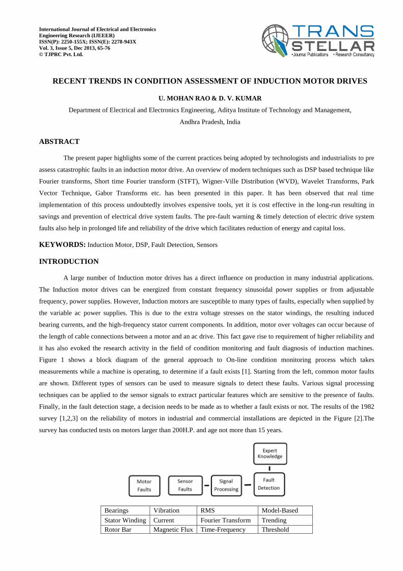
Figure 1 shows a block diagram of the general approach to On-line condition monitoring process which takes
measurements while a machine is operating, to determine if a fault exists [1]. Starting from the left, common motor faults
are shown. Different types of sensors can be used to measure signals to detect these faults. Various signal processing
techniques can be applied to the sensor signals to extract particular features which are sensitive to the presence of faults.
Finally, in the fault detection stage, a decision needs to be made as to whether a fault exists or not. The results of the 1982
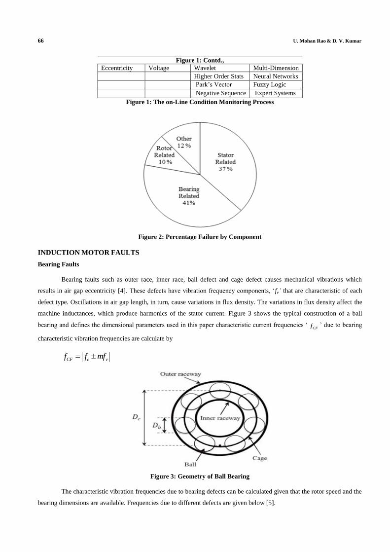
survey [1,2,3] on the reliability of motors in industrial and commercial installations are depicted in the Figure [2].The
survey has conducted tests on motors larger than 200H.P. and age not more than 15 years.
Bearings Vibration RMS Model-Based
Stator Winding Current Fourier Transform Trending
Rotor Bar Magnetic Flux Time-Frequency Threshold
66 U. Mohan Rao & D. V. Kumar
Figure 1: Contd.,
Eccentricity Voltage Wavelet Multi-Dimension
Higher Order Stats Neural Networks
Park’s Vector Fuzzy Logic
Negative Sequence Expert Systems
Figure 1: The on-Line Condition Monitoring Process
Figure 2: Percentage Failure by Component
INDUCTION MOTOR FAULTS
Bearing Faults
Bearing faults such as outer race, inner race, ball defect and cage defect causes mechanical vibrations which
results in air gap eccentricity [4]. These defects have vibration frequency components, ‘fv’ that are characteristic of each
defect type. Oscillations in air gap length, in turn, cause variations in flux density. The variations in flux density affect the
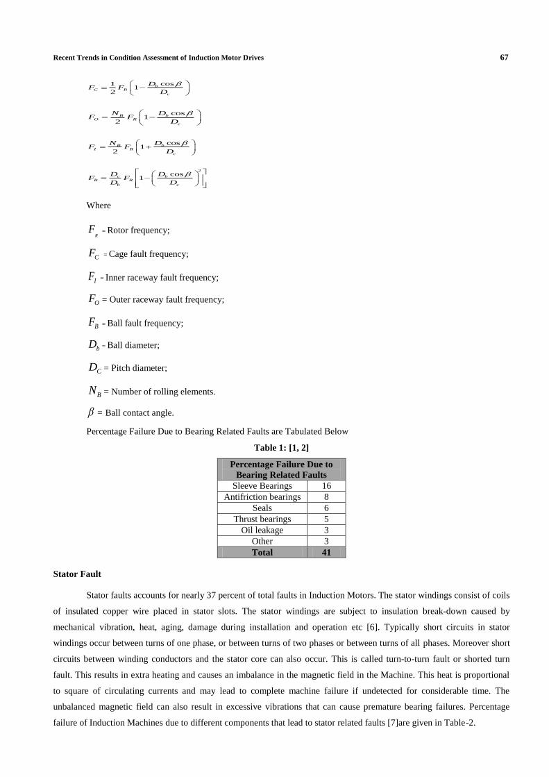
machine inductances, which produce harmonics of the stator current. Figure 3 shows the typical construction of a ball
bearing and defines the dimensional parameters used in this paper characteristic current frequencies ‘CFf ’ due to bearing
characteristic vibration frequencies are calculate by
CF e vf f mf
Figure 3: Geometry of Ball Bearing
The characteristic vibration frequencies due to bearing defects can be calculated given that the rotor speed and the
bearing dimensions are available. Frequencies due to different defects are given below [5].
Recent Trends in Condition Assessment of Induction Motor Drives 67
cos11
2
bC R
c
DF F
D
cos1
2
bBO R
c
DNF F
D
cos1
2
bBI R
c
DNF F
D
2
cos1c b
B R
b c
D DF F
D D
Where
RF = Rotor frequency;
CF = Cage fault frequency;
IF = Inner raceway fault frequency;
OF = Outer raceway fault frequency;
BF = Ball fault frequency;
bD = Ball diameter;
CD = Pitch diameter;
BN = Number of rolling elements.
= Ball contact angle.
Percentage Failure Due to Bearing Related Faults are Tabulated Below
Table 1: [1, 2]
Percentage Failure Due to
Bearing Related Faults
Sleeve Bearings 16
Antifriction bearings 8
Seals 6
Thrust bearings 5
Oil leakage 3
Other 3
Total 41
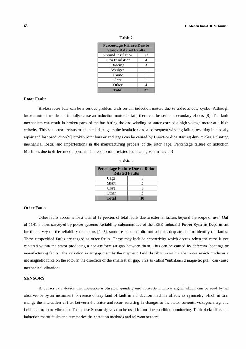
Stator Fault
Stator faults accounts for nearly 37 percent of total faults in Induction Motors. The stator windings consist of coils
of insulated copper wire placed in stator slots. The stator windings are subject to insulation break-down caused by
mechanical vibration, heat, aging, damage during installation and operation etc [6]. Typically short circuits in stator
windings occur between turns of one phase, or between turns of two phases or between turns of all phases. Moreover short
circuits between winding conductors and the stator core can also occur. This is called turn-to-turn fault or shorted turn
fault. This results in extra heating and causes an imbalance in the magnetic field in the Machine. This heat is proportional
to square of circulating currents and may lead to complete machine failure if undetected for considerable time. The
unbalanced magnetic field can also result in excessive vibrations that can cause premature bearing failures. Percentage
failure of Induction Machines due to different components that lead to stator related faults [7]are given in Table-2.
68 U. Mohan Rao & D. V. Kumar
Table 2
Percentage Failure Due to
Stator Related Faults
Ground Insulation 23
Turn Insulation 4
Bracing 3
Wedges 1
Frame 1
Core 1
Other 4
Total 37
Rotor Faults
Broken rotor bars can be a serious problem with certain induction motors due to arduous duty cycles. Although
broken rotor bars do not initially cause an induction motor to fail, there can be serious secondary effects [8]. The fault
mechanism can result in broken parts of the bar hitting the end winding or stator core of a high voltage motor at a high
velocity. This can cause serious mechanical damage to the insulation and a consequent winding failure resulting in a costly
repair and lost production[9].Broken rotor bars or end rings can be caused by Direct-on-line starting duty cycles, Pulsating
mechanical loads, and imperfections in the manufacturing process of the rotor cage. Percentage failure of Induction
Machines due to different components that lead to rotor related faults are given in Table-3
Table 3
Percentage Failure Due to Rotor
Related Faults
Cage 5
Shaft 2
Core 1
Other 2
Total 10
Other Faults
Other faults accounts for a total of 12 percent of total faults due to external factors beyond the scope of user. Out
of 1141 motors surveyed by power systems Reliability subcommittee of the IEEE Industrial Power Systems Department
for the survey on the reliability of motors [1, 2], some respondents did not submit adequate data to identify the faults.
These unspecified faults are tagged as other faults. These may include eccentricity which occurs when the rotor is not
centered within the stator producing a non-uniform air gap between them. This can be caused by defective bearings or
manufacturing faults. The variation in air gap disturbs the magnetic field distribution within the motor which produces a
net magnetic force on the rotor in the direction of the smallest air gap. This so called “unbalanced magnetic pull” can cause
mechanical vibration.
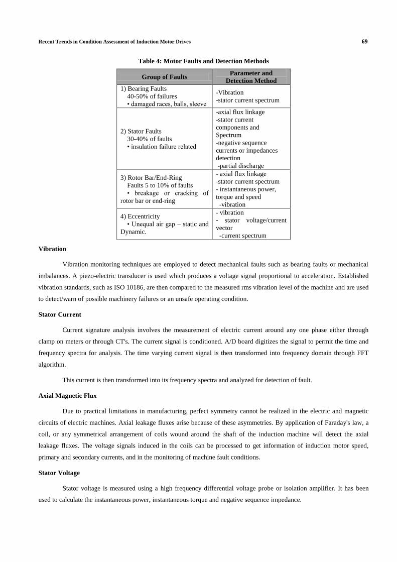
SENSORS
A Sensor is a device that measures a physical quantity and converts it into a signal which can be read by an
observer or by an instrument. Presence of any kind of fault in a Induction machine affects its symmetry which in turn
change the interaction of flux between the stator and rotor, resulting in changes to the stator currents, voltages, magnetic
field and machine vibration. Thus these Sensor signals can be used for on-line condition monitoring. Table 4 classifies the
induction motor faults and summaries the detection methods and relevant sensors.
Recent Trends in Condition Assessment of Induction Motor Drives 69
Table 4: Motor Faults and Detection Methods
Group of Faults Parameter and
Detection Method
1) Bearing Faults
40-50% of failures
• damaged races, balls, sleeve
-Vibration
-stator current spectrum
2) Stator Faults
30-40% of faults
• insulation failure related
-axial flux linkage
-stator current
components and
Spectrum
-negative sequence
currents or impedances
detection
-partial discharge
3) Rotor Bar/End-Ring
Faults 5 to 10% of faults
• breakage or cracking of
rotor bar or end-ring
- axial flux linkage
-stator current spectrum
- instantaneous power,
torque and speed
-vibration
4) Eccentricity
• Unequal air gap – static and
Dynamic.
- vibration
- stator voltage/current
vector
-current spectrum
Vibration
Vibration monitoring techniques are employed to detect mechanical faults such as bearing faults or mechanical
imbalances. A piezo-electric transducer is used which produces a voltage signal proportional to acceleration. Established
vibration standards, such as ISO 10186, are then compared to the measured rms vibration level of the machine and are used
to detect/warn of possible machinery failures or an unsafe operating condition.
Stator Current
Current signature analysis involves the measurement of electric current around any one phase either through
clamp on meters or through CT's. The current signal is conditioned. A/D board digitizes the signal to permit the time and
frequency spectra for analysis. The time varying current signal is then transformed into frequency domain through FFT
algorithm.
This current is then transformed into its frequency spectra and analyzed for detection of fault.
Axial Magnetic Flux
Due to practical limitations in manufacturing, perfect symmetry cannot be realized in the electric and magnetic
circuits of electric machines. Axial leakage fluxes arise because of these asymmetries. By application of Faraday's law, a
coil, or any symmetrical arrangement of coils wound around the shaft of the induction machine will detect the axial
leakage fluxes. The voltage signals induced in the coils can be processed to get information of induction motor speed,
primary and secondary currents, and in the monitoring of machine fault conditions.
Stator Voltage
Stator voltage is measured using a high frequency differential voltage probe or isolation amplifier. It has been
used to calculate the instantaneous power, instantaneous torque and negative sequence impedance.
70 U. Mohan Rao & D. V. Kumar
Other Kind of Sensory Parameters
Thermal monitoring, Torque monitoring and Noise monitoring are some of the other techniques that are employed
for condition monitoring of induction machines.
A stator current faults generates excessive heat in the shorted turns, and increased bearing wear increases the
friction and the temperature in that region of the machine. This increase in temperature of motor can be a detected by
thermal monitoring which helps in preventing excessive detoriation of insulation.
Noise and vibration in electric machines are caused by forces which are of magnetic, mechanical and aerodynamic
origin. Vibration signal of an electric machine is analysed to detect various types of faults and asymmetries. The major
disadvantage of vibration monitoring is cost. It is very costly when compared to other condition monitoring techniques.Cost
effective sensor less online vibration monitoring techniques are proposed which are based on the relationship between the
current harmonics in the machine and their related vibration harmonics. Partial discharge analysis is also carried out for
detecting stator insulation faults in higher voltage motors.
SIGNAL PROCESSING METHODS
Frequency Domain
Fast Fourier Transforms (FFT)
Time-Frequency Techniques
Short Time Fourier Transform (STFT)
Gabor Transform (GT)
Cohen class distribution
o Wigner –Ville distribution (WVD)
o Choi-Williams distribution
o Cone shaped distribution
Wavelet Transform (WT)
Discrete Wavelet Transform (DWT)
Discrete Wavelet Transform (DWT) for Multi resolution Analysis (MRA).
Park’s Vector Approach
Time Series Methods
Spectral estimation through ARMA models
Welch method
Music method
Periodogram
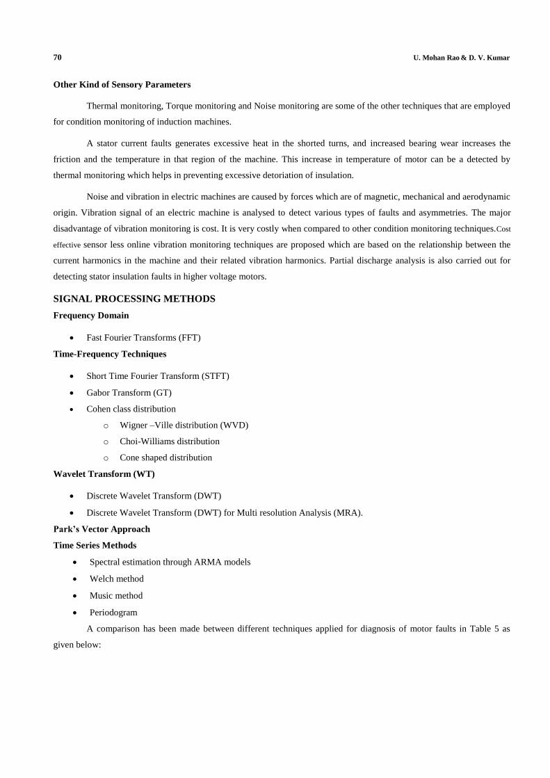
A comparison has been made between different techniques applied for diagnosis of motor faults in Table 5 as
given below:
Recent Trends in Condition Assessment of Induction Motor Drives 71
Table 5: Comparison of Techniques Applied for Diagnosis of Motor Faults
Techniques
Required
Measureme-
Nt
Faults
Diagnosed
Advantages
Disadvantages
FFT One stator
current
•Broken rotor
bar fault
•Short
winding fault
•Airgap
eccentricity
•Bearing
faults
• Load fault
•Suitable for
high load
conditions
• Easy to
implement
• Lost time
information
• Not effective at
light load
condition
STFT One stator
current
•Broken rotor
bar fault
•Short
winding fault
•Air gap
eccentricity
•Bearing
faults
• Load fault
•Suitable for
high load
conditions
• Easy to
implement
• Lost time
information
• Not effective at
light load
condition
Gabor
Transform
One Stator
Current
•Short
winding Fault
•Fine
frequency
resolution
•Moderate speed
Wavelet
Transform
One Stator
Current
•Broken rotor
bar fault
•Short
winding fault
•Suitable for
varying load
and light load
conditions
•Require
expertise
Wigner
Ville
distribution
One Stator
Current •Bearing fault
•Fine
frequency
resolution
•Fast speed
•Strong cross
term
interference
Park
Vector
Approach
Three Stator
Currents
•Short
winding faults
•Bearing
faults
•Easy to
diagnose
the fault
•Not effective
for load faults
and broken rotor
bar fault
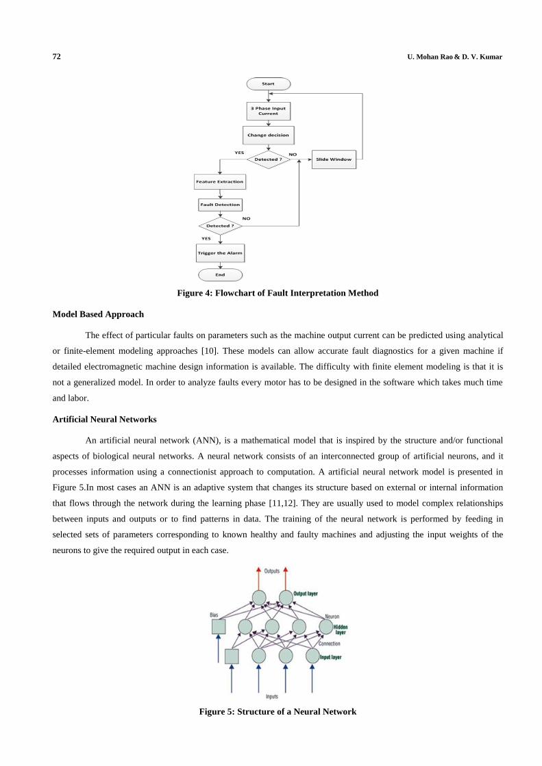
FAULT INTERPRETATION METHODS
Fault Diagnosis can be a complex reasoning activity, which is currently one of the domains where Artificial
Intelligence techniques have been successfully applied.
The reason is that these techniques use association, reasoning and decision making processes as would the human
brain in solving diagnostic problems. Fault parameters extracted using the signal processing techniques are now used to
decide if a fault exists and if so, what type of fault. Figure 4 shows the flowchart of the fault detection scheme [4].
The process can be divided into three main stages: detection, feature extraction and fault identifier. Experience
and knowledge of an expert user is used to distinguish between a healthy and faulty machine. Artificial intelligence and
pattern recognition techniques aids in automating the fault interpretation process.
72 U. Mohan Rao & D. V. Kumar
Figure 4: Flowchart of Fault Interpretation Method
Model Based Approach
The effect of particular faults on parameters such as the machine output current can be predicted using analytical
or finite-element modeling approaches [10]. These models can allow accurate fault diagnostics for a given machine if
detailed electromagnetic machine design information is available. The difficulty with finite element modeling is that it is
not a generalized model. In order to analyze faults every motor has to be designed in the software which takes much time
and labor.
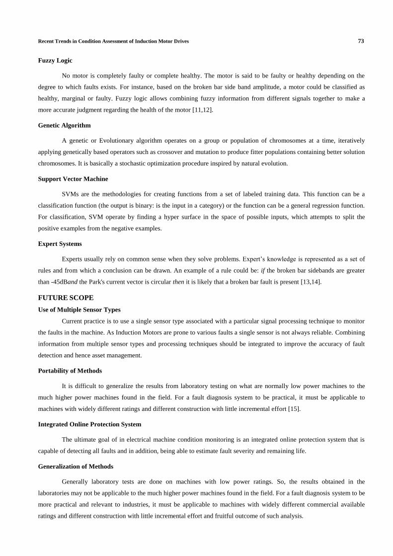
Artificial Neural Networks
An artificial neural network (ANN), is a mathematical model that is inspired by the structure and/or functional
aspects of biological neural networks. A neural network consists of an interconnected group of artificial neurons, and it
processes information using a connectionist approach to computation. A artificial neural network model is presented in
Figure 5.In most cases an ANN is an adaptive system that changes its structure based on external or internal information
that flows through the network during the learning phase [11,12]. They are usually used to model complex relationships
between inputs and outputs or to find patterns in data. The training of the neural network is performed by feeding in
selected sets of parameters corresponding to known healthy and faulty machines and adjusting the input weights of the
neurons to give the required output in each case.
Figure 5: Structure of a Neural Network
Recent Trends in Condition Assessment of Induction Motor Drives 73
Fuzzy Logic
No motor is completely faulty or complete healthy. The motor is said to be faulty or healthy depending on the
degree to which faults exists. For instance, based on the broken bar side band amplitude, a motor could be classified as
healthy, marginal or faulty. Fuzzy logic allows combining fuzzy information from different signals together to make a
more accurate judgment regarding the health of the motor [11,12].
Genetic Algorithm
A genetic or Evolutionary algorithm operates on a group or population of chromosomes at a time, iteratively
applying genetically based operators such as crossover and mutation to produce fitter populations containing better solution
chromosomes. It is basically a stochastic optimization procedure inspired by natural evolution.
Support Vector Machine
SVMs are the methodologies for creating functions from a set of labeled training data. This function can be a
classification function (the output is binary: is the input in a category) or the function can be a general regression function.
For classification, SVM operate by finding a hyper surface in the space of possible inputs, which attempts to split the
positive examples from the negative examples.
Expert Systems
Experts usually rely on common sense when they solve problems. Expert’s knowledge is represented as a set of
rules and from which a conclusion can be drawn. An example of a rule could be: if the broken bar sidebands are greater
than -45dBand the Park's current vector is circular then it is likely that a broken bar fault is present [13,14].
FUTURE SCOPE
Use of Multiple Sensor Types
Current practice is to use a single sensor type associated with a particular signal processing technique to monitor
the faults in the machine. As Induction Motors are prone to various faults a single sensor is not always reliable. Combining
information from multiple sensor types and processing techniques should be integrated to improve the accuracy of fault
detection and hence asset management.
Portability of Methods
It is difficult to generalize the results from laboratory testing on what are normally low power machines to the
much higher power machines found in the field. For a fault diagnosis system to be practical, it must be applicable to
machines with widely different ratings and different construction with little incremental effort [15].
Integrated Online Protection System
The ultimate goal of in electrical machine condition monitoring is an integrated online protection system that is
capable of detecting all faults and in addition, being able to estimate fault severity and remaining life.
Generalization of Methods
Generally laboratory tests are done on machines with low power ratings. So, the results obtained in the
laboratories may not be applicable to the much higher power machines found in the field. For a fault diagnosis system to be
more practical and relevant to industries, it must be applicable to machines with widely different commercial available
ratings and different construction with little incremental effort and fruitful outcome of such analysis.
74 U. Mohan Rao & D. V. Kumar
Remote Machine Monitoring
Induction machines equipped in remote sites or in hazardous locations (such as remote mining sites or petroleum
processing plants) are not always accessible. It necessitates remote monitoring which may be developed in future.
CONCLUSIONS
The present paper covered an exhaustive detail about several issues concerning fault diagnosis trends for
induction motor drives. An overview of current trends in this area has been dealt with necessary implantation software
requirements for improving induction motor drive reliability and fault diagnosis. This will enhance asset management
strategies of the organization and reduce maintenance cost and hence the production loss.
REFERENCES
1. IAS Motor Reliability Working Group, “Report of Large Motor Reliability Survey of Industrial and Commercial
Installations –Part I,” IEEE Trans. on Ind. Appl., vol. 21, Jul./Aug. 1985, pp.853-864.
2. IAS Motor Reliability Working Group, “Report of Large Motor Reliability Survey of Industrial and Commercial
Installations –Part II,”IEEE Trans. on Ind. Appl., vol. 21, Jul./Aug. 1985, pp.865-872.
3. O.V. Thorsen and M. Dalva, “Failure Identification and Analysis for High-Voltage Induction Motors in the
Petrochemical Industry,” IEEE Trans.on Ind. Appl., vol. 35, no.4, , pp. 810-818,Jul./Aug. 1999.
4. Jack, L. B., and Nandi, A. K., “Genetic algorithm for feature selection in machine condition monitoring with
vibration signals”, IEEE Proceedings Vision, Image and Signal Processing, Vol. 147, June, pp. 205-212, 2000.
5. P. Vas, “Parameter Estimation, Condition Monitoring, and Diagnosis of Electrical Machines,” Clarendon Press,
Oxford,1993.
6. J. Sottile and J. L. Kohler, “An on-line method to detect incipient failure of turn insulation in random-wound
motors,” IEEE Transactions on Energy Conversion, vol. 8,no. 4, pp. 762-768, December, 1993.
7. A.H. Bonnet and G. C. Soukup, “Cause and analysis of stator and rotor failures in three phase squirrel case
induction motors,” IEEE Transactions Industry Application, Vol.,28, No.4, pp. 921-937, July/August, 1992.
8. Andrea Stefani, Alberto Bellini, and Fiorenzo Filippetti,” Diagnosis of Induction Machines Rotor Faults in Time-
Varying Conditions” ,IEEE transactions on industrial electronics, VOL. 56, NO. 11, NOVEMBER 2009.
9. L. Cristaldi, M. Faifer, L. Piegari, M. Rossi, and S. Toscani,”Rotor fault detection in field oriented controlled
induction machines” ,SPEEDAM 2010,International Symposium on Power Electronics ,Electrical Drives,
Automation and Motion.
10. J.Mur,J.S.Artal, J.Letosa, A.Usón and M.Samplón,” finite elements softwares for electromagnetics applied to
electrical engineering training”, International Conference on Engineering Education, July 21–25, 2003, Valencia,
Spain.
11. M.Y. Chow, “Methodologies of Using Neural Network and Fuzzy Logic Technologies for Motor Incipient Fault
Detection,” World Scientific, Singapore, 1997.
Recent Trends in Condition Assessment of Induction Motor Drives 75
12. F. Filippetti, C. Tassoni, G. Franceschini and P. Vas, “Integrated Condition Monitoring and Diagnosis of
Electrical Machines Using Minimum Configuration Artificial Intelligence” European Power Electronics Conf.,
1997, pp. 2.983-2.988.
13. F. Filippetti and M. Martelli, “Development of Expert System Knowledge Base to On-Line Diagnosis of Rotor
Electrical Faults of Induction Motors,” IEEE Ind. Appl. Society Annual Meeting, vol. 1, 1992, pp. 92-99.
14. E. Styvaktakis, M.H.J. Bollen and I.Y.H. Gu, “Expert System for Classification and Analysis of Power System
Events,” IEEE Trans. on Power Delivery, vol. 17, no. 2, Apr. 2002, pp. 423-428.
15. K. Kim and A. G. Parlos, “Induction Motor Fault Diagnosis Based on Neuro predictors and Wavelet Signal
Processing,” IEEE/ASME Trans. on Mechatronics, vol. 7, no. 2, Jun. 2002,pp. 201-219.
AUTHOR’S DETAILS
U.Mohan Rao completed his graduation in Electrical & Electronics Engineering from Jawaharlal Nehru
Technological University, Kakinada in 2010 and received his Masters of Technology in Condition Monitoring and Control
from National Institute of Technology-Hamirpur, India in 2012. Currently he is working as Assistant Professor in the
Department of Electrical & Electronics Engineering Aditya Institute of Technology and Management- Tekkali,
Srikakulam. His research interests include Transformer Diagnostics, Computational Intelligence in Machine Diagnosis and
Optimization in Condition monitoring.
Dr.Vijay Kumar completed his graduation in Electrical & Electronics Engineering from Andhra University,
Visakhapatnam in 1997 and received his M.E. in Power Systems from Andhra University, India in 2000. He received his
Ph.D. in the year 2010 from Andhra University. He served as an Assistant Professor and Associate Professor in various
Engineering colleges during 2000-2010 and at presently he is working as Professor and head in the Department of
Electrical & Electronics Engineering Aditya Institute of Technology and Management- Tekkali, Srikakulam. His areas of
interest are, Power System & Control Systems.