Embed Size (px)
Citation preview
198
Recent Upgrading and Life Extension Technologies
for Existing Steam Turbines∗
Toshio SUZUKI∗∗, Toshihiro MATSUURA∗∗, Akira SAKUMA∗∗,Hirotsugu KODAMA∗∗, Kentaro TAKAGI∗∗ and Andrew CURTIS∗∗
Electricity generation utilities are increasingly looking for cost-effective solutions tomaximise the value of aging steam turbine generator plant assets. To this end, retrofits ofsteam turbines after many years of operation have been carried out for the purpose of lifeextension of units, performance improvements, capacity up-rating, availability improvement,and improved environmental compliance. Major steam turbine manufacturers have continuedto push forward the development of advanced technologies to satisfy demand from utilitiesby provided retrofit design that optimise the above criteria. This paper describes the ad-vanced technologies adopted in the recent retrofits, including advanced steam path designand new last stage blades of improved efficiency, improved reliability, and of simplified or nomaintenance. Retrofit case-studies of capacity up-rating and life extension are introduced toillustrate how these technologies have been applied and what has been the gain.
Key Words: Power Generation, Steam Turbine
1. Introduction
It has been widely recognized that the retrofit of oldunits is one of the most cost-effective solutions in optimis-ing installed plant asset value. The type of benefits thatcan be expected by retrofitting consist of the followings.
( 1 ) Life extensionRestoration or improvement of resistance against creeprupture/SPE of HIP section and erosion/corrosion of LPsection
( 2 ) Increased power outputA higher value of output at base load and in peak demandperiods, sometimes with a load swing operation
( 3 ) Improved turbine efficiencyFundamental characteristics, normally indispensable to in-crease power output
( 4 ) Improved unit availability and maintainabilityExtended outage inspection and overhaul intervals en-abled by increased equipment reliability, shorter overhaulsdurations from use of simplified or no-maintenance equip-ment.
In order to achieve these retrofit benefits, the author’s
∗ Received 31st August, 2005 (No. 05-4151)∗∗ Toshiba Corporation, 2–4 Suehiro-cho, Tsurumi, Yoko-
hama, Kanagawa 230–0045, Japan.E-mail: [email protected]
company has developed the following advanced technolo-gies and applied them with equal success to equipmentoriginally designed and manufactured by our own andother companies. More than 200 units have been suc-cessfully upgraded. The author’s company’s experiencein major turbine component replacement is represented inFig. 1.
2. Advanced Technologies for Retrofits
2. 1 Steam path efficiency improvementNewly-developed technologies to improve turbine ef-
ficiency have been applied incrementally as they havebeen developed to upgrade existing turbines since early1980s. Internal losses within a steam turbine arises from
Fig. 1 Experience of component replacement
Series B, Vol. 49, No. 2, 2006 JSME International Journal
199
various factors, accordingly, the analysis of these factorsis very important in order to assess the actual gain in effi-ciency(1).
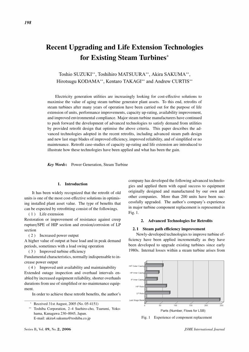
So-called secondary loss is one of the most signifi-cant losses in a steam turbine, occurring in the flow nearthe intersection of end-walls and airfoils. Large-scale vor-tices, and the boundary layer growth in this zone cause thesecondary loss. To reduce the secondary loss, the massflow distribution along the blade height is controlled asshown in Fig. 2. It is characterized by lower mass flow atthe tip and root zones, where the efficiency is lower dueto the secondary loss, while mass flow is higher at mid-span where the efficiency is higher. This design, calledAdvanced Flow Pattern (AFP), reduces the total energyloss. To reduce the secondary loss near the end-walls, thegrowth of boundary layers must be suppressed. With thedesign of leaning nozzles and/or blades, the streamlinesnear the end-walls are shifted towards the wall, thus avoid-ing the growth of boundary layer. Nozzle diaphragms orblades of compound lean design as shown in Fig. 3 havebeen widely applied.
The velocity or pressure (loading) distribution on theblade profile is directly related to the stage efficiency. Itcontrols not only the 2D (two dimensional) profile loss,but the secondary flow loss also. There are two types ofloading pattern in the current design of blade profiles. Oneis the front-loaded pattern with which the velocity on suc-tion surface reaches a maximum near the inlet. It shows anexcellent 2D performance, but the large deflection of flowjust downstream of the leading edge produces large cross-channel pressure gradient resulting in a strong passagevortex on the end-walls. This type is suitable for longerlength blades. The other pattern is the aft-loaded patternwith which the velocity on the suction surface reaches amaximum as far downstream as possible. Strong passagevortices do not occur in this pattern, resulting in reducedsecondary losses. This type is suitable for short blades.
Blade trailing edge loss greatly contributes to reduc-tion in turbine efficiency. It is caused by wake flow withlower velocity downstream of the trailing edge of bladesas shown in Fig. 4. An effective method to reduce trail-ing edge loss is to reduce the number of blades by apply-
Fig. 2 Improved flow pattern
ing large pitch blades without increasing the trailing edgethickness. The simple reduction of the number of bladesby magnifying the blade profile and modifying the trailingedge thickness can be a solution. In such case, the as-pect ratio of blade (blade height/chord length) is reduced,resulting in the possible increase in secondary loss. A spe-cial blade profile has been developed and tested for largepitch design as shown in Fig. 4.
The surface roughness of blade profiles significantlyaffects the turbine’s efficiency, particularly in the stages ofhigher Reynolds number flow in the HP and IP sections.Blade profile loss is related to the growth of a boundarylayer on the profile surface, which is caused by friction be-tween the main flow and the blade surface. To improve the
Fig. 3 Lean nozzles and blades
Fig. 4 Large pitch profile design
JSME International Journal Series B, Vol. 49, No. 2, 2006
200
Fig. 5 Dynamic test for sensitized packing
surface condition of blades, special polishing technologyhas been developed. Special polishing particles, which areejected from a blasting nozzle, impinge and slip on theblade surface, and polish the nozzle surface. This technol-ogy of surface roughness improvement can be applied toremovable nozzle diaphragms or fully lades rotors duringoverhaul of a unit at site or in a workshop.
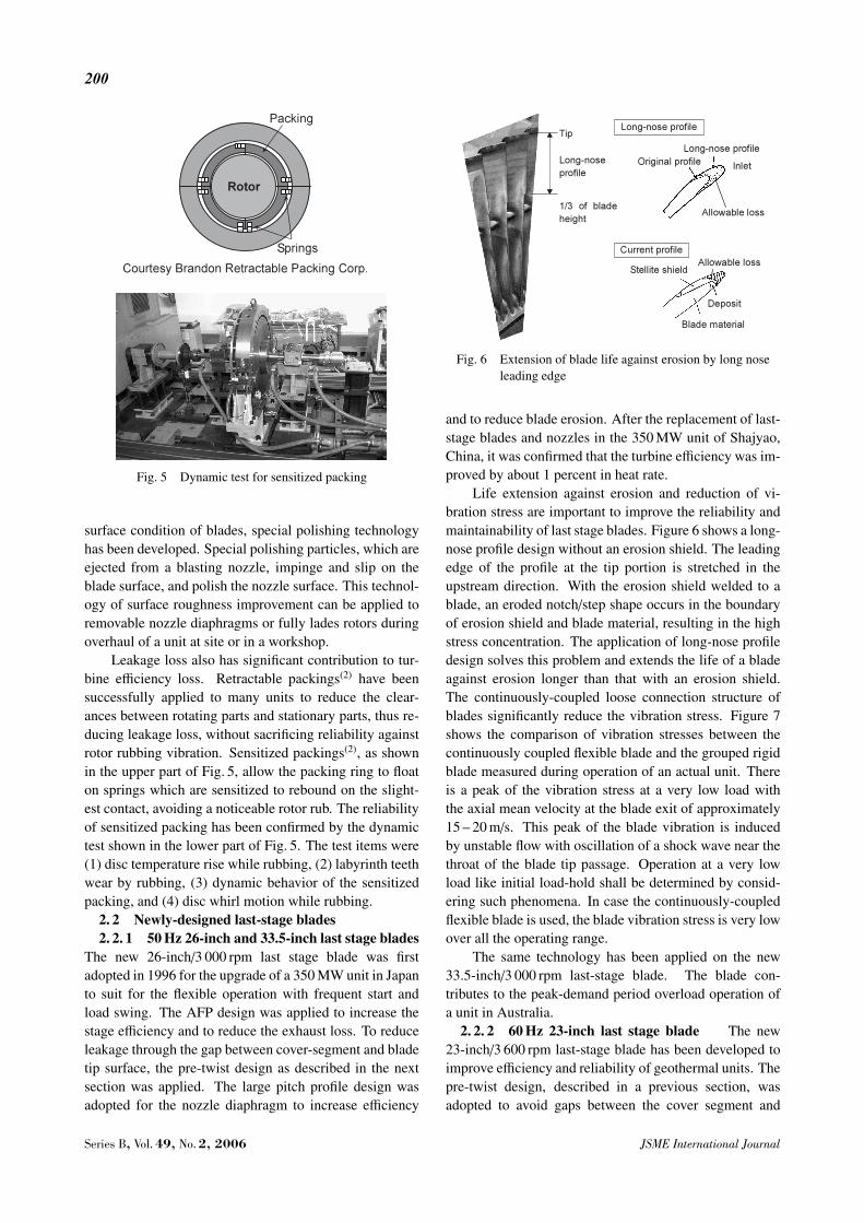
Leakage loss also has significant contribution to tur-bine efficiency loss. Retractable packings(2) have beensuccessfully applied to many units to reduce the clear-ances between rotating parts and stationary parts, thus re-ducing leakage loss, without sacrificing reliability againstrotor rubbing vibration. Sensitized packings(2), as shownin the upper part of Fig. 5, allow the packing ring to floaton springs which are sensitized to rebound on the slight-est contact, avoiding a noticeable rotor rub. The reliabilityof sensitized packing has been confirmed by the dynamictest shown in the lower part of Fig. 5. The test items were(1) disc temperature rise while rubbing, (2) labyrinth teethwear by rubbing, (3) dynamic behavior of the sensitizedpacking, and (4) disc whirl motion while rubbing.
2. 2 Newly-designed last-stage blades2. 2. 1 50 Hz 26-inch and 33.5-inch last stage blades
The new 26-inch/3 000 rpm last stage blade was firstadopted in 1996 for the upgrade of a 350 MW unit in Japanto suit for the flexible operation with frequent start andload swing. The AFP design was applied to increase thestage efficiency and to reduce the exhaust loss. To reduceleakage through the gap between cover-segment and bladetip surface, the pre-twist design as described in the nextsection was applied. The large pitch profile design wasadopted for the nozzle diaphragm to increase efficiency
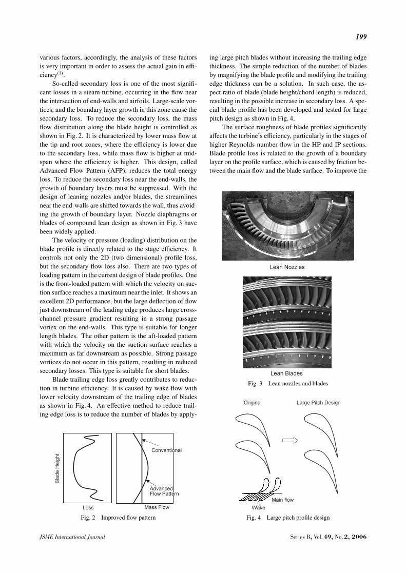
Fig. 6 Extension of blade life against erosion by long noseleading edge
and to reduce blade erosion. After the replacement of last-stage blades and nozzles in the 350 MW unit of Shajyao,China, it was confirmed that the turbine efficiency was im-proved by about 1 percent in heat rate.
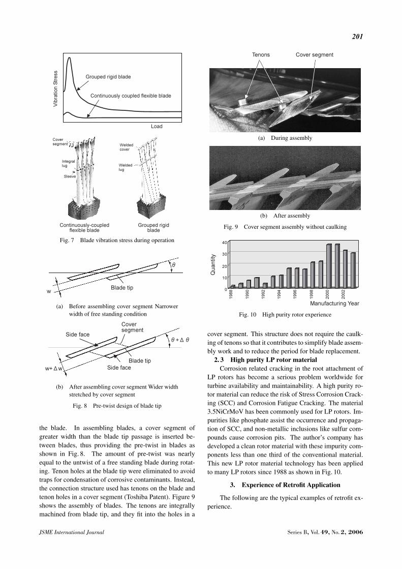
Life extension against erosion and reduction of vi-bration stress are important to improve the reliability andmaintainability of last stage blades. Figure 6 shows a long-nose profile design without an erosion shield. The leadingedge of the profile at the tip portion is stretched in theupstream direction. With the erosion shield welded to ablade, an eroded notch/step shape occurs in the boundaryof erosion shield and blade material, resulting in the highstress concentration. The application of long-nose profiledesign solves this problem and extends the life of a bladeagainst erosion longer than that with an erosion shield.The continuously-coupled loose connection structure ofblades significantly reduce the vibration stress. Figure 7shows the comparison of vibration stresses between thecontinuously coupled flexible blade and the grouped rigidblade measured during operation of an actual unit. Thereis a peak of the vibration stress at a very low load withthe axial mean velocity at the blade exit of approximately15 – 20 m/s. This peak of the blade vibration is inducedby unstable flow with oscillation of a shock wave near thethroat of the blade tip passage. Operation at a very lowload like initial load-hold shall be determined by consid-ering such phenomena. In case the continuously-coupledflexible blade is used, the blade vibration stress is very lowover all the operating range.
The same technology has been applied on the new33.5-inch/3 000 rpm last-stage blade. The blade con-tributes to the peak-demand period overload operation ofa unit in Australia.
2. 2. 2 60 Hz 23-inch last stage blade The new23-inch/3 600 rpm last-stage blade has been developed toimprove efficiency and reliability of geothermal units. Thepre-twist design, described in a previous section, wasadopted to avoid gaps between the cover segment and
Series B, Vol. 49, No. 2, 2006 JSME International Journal
201
Fig. 7 Blade vibration stress during operation
(a) Before assembling cover segment Narrowerwidth of free standing condition
(b) After assembling cover segment Wider widthstretched by cover segment
Fig. 8 Pre-twist design of blade tip
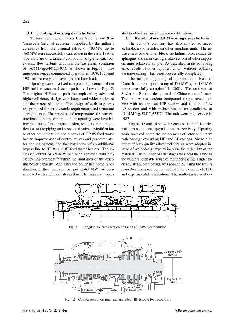
the blade. In assembling blades, a cover segment ofgreater width than the blade tip passage is inserted be-tween blades, thus providing the pre-twist in blades asshown in Fig. 8. The amount of pre-twist was nearlyequal to the untwist of a free standing blade during rotat-ing. Tenon holes at the blade tip were eliminated to avoidtraps for condensation of corrosive contaminants. Instead,the connection structure used has tenons on the blade andtenon holes in a cover segment (Toshiba Patent). Figure 9shows the assembly of blades. The tenons are integrallymachined from blade tip, and they fit into the holes in a
(a) During assembly
(b) After assembly
Fig. 9 Cover segment assembly without caulking
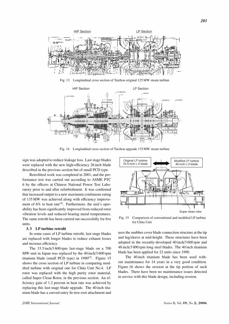
Fig. 10 High purity rotor experience
cover segment. This structure does not require the caulk-ing of tenons so that it contributes to simplify blade assem-bly work and to reduce the period for blade replacement.
2. 3 High purity LP rotor materialCorrosion related cracking in the root attachment of
LP rotors has become a serious problem worldwide forturbine availability and maintainability. A high purity ro-tor material can reduce the risk of Stress Corrosion Crack-ing (SCC) and Corrosion Fatigue Cracking. The material3.5NiCrMoV has been commonly used for LP rotors. Im-purities like phosphate assist the occurrence and propaga-tion of SCC, and non-metallic inclusions like sulfur com-pounds cause corrosion pits. The author’s company hasdeveloped a clean rotor material with these impurity com-ponents less than one third of the conventional material.This new LP rotor material technology has been appliedto many LP rotors since 1988 as shown in Fig. 10.
3. Experience of Retrofit Application
The following are the typical examples of retrofit ex-perience.
JSME International Journal Series B, Vol. 49, No. 2, 2006
202
3. 1 Uprating of existing steam turbinesTurbine uprating of Tacoa Unit No.7, 8 and 9 in
Venezuela (original equipment supplied by the author’scompany) from the original rating of 400 MW up to460 MW were successfully carried out in the early 1990’s.The units are of a tandem compound, single reheat, fourexhaust flow turbine with main/reheat steam conditionof 16.8 MPag/540◦C/540◦C as shown in Fig. 11. Theunits commenced commercial operation in 1979, 1979 and1981 respectively and have operated base load.
Uprating work involved complete replacement of theHIP turbine rotor and steam path, as shown in Fig. 12.The original HIP steam path was replaced by advancedhigher efficiency design with longer and wider blades tosuit the increased output. The design of each stage wasre-optimized for aerodynamic requirements and structuralstrength limits. The pressure and temperature of steam ex-tractions at the maximum load for uprating were kept be-low the limits of the original design, resulting in no modi-fication of the piping and associated valves. Modificationto other equipment include renewal of HP #5 feed waterheater, improvement of control valves and generator sta-tor cooling system, and the installation of an additionalbypass line to HP #6 and #7 feed water heaters. The in-creased output of 450 MW had been achieved with effi-ciency improvement(3) within the limitation of the exist-ing boiler capacity. And after the boiler had some mod-ification, further increased out put of 460 MW had beenachieved with additional steam flow. The units have oper-
Fig. 11 Longitudinal cross section of Tacoa 400 MW steam turbine
Fig. 12 Comparison of original and upgraded HIP turbine for Tacoa Unit
ated trouble-free since upgrade modification.3. 2 Retrofit of non-OEM existing steam turbines
The author’s company has also applied advancedtechnologies to retrofits on other suppliers units. The re-placement of the inner block, including rotor, nozzle di-aphragms and inner casing, makes retrofit of other suppli-ers units relatively simple. As described in the followingcase, retrofit of other suppliers units—without replacingthe inner casing—has been successfully completed.
The turbine upgrading of Taizhou Unit No.1 inChina from the original rating of 125 MW up to 135 MWwas successfully completed in 2001. The unit was ofSoviet-era Russian design and of Chinese manufacture.The unit was a tandem compound single reheat tur-bine with an opposed HIP section and a double flowLP section and with main/reheat steam conditions of13.14 MPag/535◦C/535◦C. The unit went into service in1982.
Figures 13 and 14 show the cross section of the orig-inal turbine and the upgraded one respectively. Upratingwork involved complete replacement of rotor and steampath package excluding HIP and LP casings. Mono-blocrotors of high-quality alloy steel forging were adopted in-stead of welded-disc type to increase the reliability of thematerial. The number of HIP stages was kept the same asthe original to enable reuse of the inner casing. High effi-ciency steam path design was applied by using the resultsfrom 3-dimensional computational fluid dynamics (CFD)and experimental verification. The multi-fin tip seal de-
Series B, Vol. 49, No. 2, 2006 JSME International Journal
203
Fig. 13 Longitudinal cross section of Taizhou original 125 MW steam turbine
Fig. 14 Longitudinal cross section of Taizhou upgrade 135 MW steam turbine
sign was adopted to reduce leakage loss. Last stage bladeswere replaced with the new high-efficiency 26 inch bladedescribed in the previous section but of small PCD type.
Retrofitted work was completed in 2001, and the per-formance test was carried out according to ASME PTC6 by the officers at Chinese National Power Test Labo-ratory prior to and after refurbishment. It was confirmedthat increased output to a new maximum continuous ratingof 135 MW was achieved along with efficiency improve-ment of 6% in heat rate(4). Furthermore, the unit’s oper-ability has been significantly improved from reduced rotorvibration levels and reduced bearing metal temperatures.The same retrofit has been carried out successfully for fiveunits.
3. 3 LP turbine retrofitIn some cases of LP turbine retrofit, last-stage blades
are replaced with longer blades to reduce exhaust lossesand increase efficiency.
The 33.5 inch/3 600 rpm last-stage blade on a 700MW unit in Japan was replaced by the 40 inch/3 600 rpmtitanium blade (small PCD type) in 1990(5). Figure 15shows the cross section of LP turbine in comparing mod-ified turbine with original one for Chita Unit No.4. LProtor was replaced with the high purity rotor material,called Super Clean Rotor, in the previous section. An ef-ficiency gain of 1.2 percent in heat rate was achieved byreplacing this last-stage blade upgrade. The 40 inch tita-nium blade has a curved-entry fir-tree root attachment and
Fig. 15 Comparison of conventional and modified LP turbinefor Chita Unit
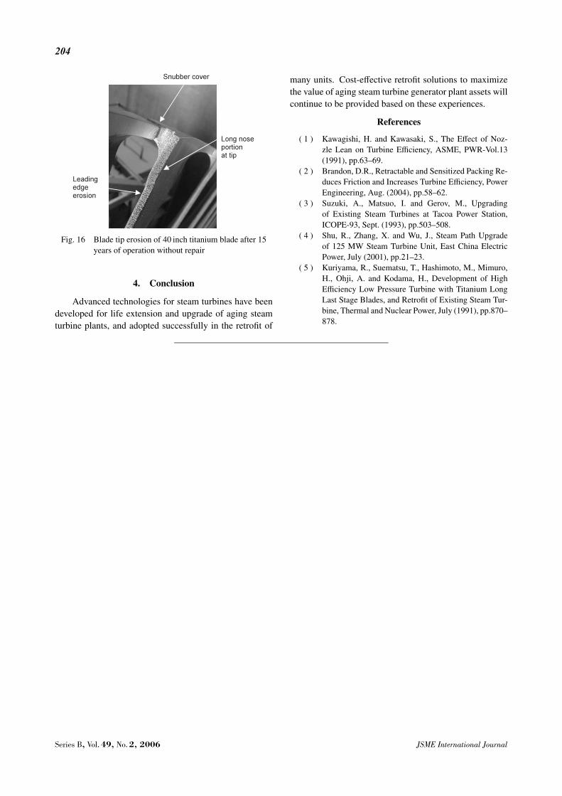
uses the snubber cover blade connection structure at the tipand lug/sleeve at mid-height. These structures have beenadopted in the recently-developed 40 inch/3 600 rpm and48 inch/3 000 rpm long steel blades. The 40 inch titaniumblade has been applied for 22 units since 1990.
The 40 inch titanium blade has been used with-out maintenance for 14 years in a very good condition.Figure 16 shows the erosion at the tip portion of suchblades. There have been no maintenance issues detectedin service with this blade design, including erosion.
JSME International Journal Series B, Vol. 49, No. 2, 2006
204
Fig. 16 Blade tip erosion of 40 inch titanium blade after 15years of operation without repair
4. Conclusion
Advanced technologies for steam turbines have beendeveloped for life extension and upgrade of aging steamturbine plants, and adopted successfully in the retrofit of
many units. Cost-effective retrofit solutions to maximizethe value of aging steam turbine generator plant assets willcontinue to be provided based on these experiences.
References
( 1 ) Kawagishi, H. and Kawasaki, S., The Effect of Noz-zle Lean on Turbine Efficiency, ASME, PWR-Vol.13(1991), pp.63–69.
( 2 ) Brandon, D.R., Retractable and Sensitized Packing Re-duces Friction and Increases Turbine Efficiency, PowerEngineering, Aug. (2004), pp.58–62.
( 3 ) Suzuki, A., Matsuo, I. and Gerov, M., Upgradingof Existing Steam Turbines at Tacoa Power Station,ICOPE-93, Sept. (1993), pp.503–508.
( 4 ) Shu, R., Zhang, X. and Wu, J., Steam Path Upgradeof 125 MW Steam Turbine Unit, East China ElectricPower, July (2001), pp.21–23.
( 5 ) Kuriyama, R., Suematsu, T., Hashimoto, M., Mimuro,H., Ohji, A. and Kodama, H., Development of HighEfficiency Low Pressure Turbine with Titanium LongLast Stage Blades, and Retrofit of Existing Steam Tur-bine, Thermal and Nuclear Power, July (1991), pp.870–878.
Series B, Vol. 49, No. 2, 2006 JSME International Journal