Embed Size (px)
Citation preview
Recommendation ITU-R SF.675-4(01/2012)
Calculation of the maximum power density (averaged over 4 kHz or 1 MHz)
of angle-modulated and digital carriers
SF SeriesFrequency sharing and coordination between
fixed-satellite and fixed service systems
ii Rec. ITU-R SF.675-4
Foreword
The role of the Radiocommunication Sector is to ensure the rational, equitable, efficient and economical use of the radio-frequency spectrum by all radiocommunication services, including satellite services, and carry out studies without limit of frequency range on the basis of which Recommendations are adopted.
The regulatory and policy functions of the Radiocommunication Sector are performed by World and Regional Radiocommunication Conferences and Radiocommunication Assemblies supported by Study Groups.
Policy on Intellectual Property Right (IPR)
ITU-R policy on IPR is described in the Common Patent Policy for ITU-T/ITU-R/ISO/IEC referenced in Annex 1 of Resolution ITU-R 1. Forms to be used for the submission of patent statements and licensing declarations by patent holders are available from http://www.itu.int/ITU-R/go/patents/en where the Guidelines for Implementation of the Common Patent Policy for ITU-T/ITU-R/ISO/IEC and the ITU-R patent information database can also be found.
Series of ITU-R Recommendations
(Also available online at http://www.itu.int/publ/R-REC/en)
Series Title
BO Satellite delivery
BR Recording for production, archival and play-out; film for television
BS Broadcasting service (sound)
BT Broadcasting service (television)
F Fixed service
M Mobile, radiodetermination, amateur and related satellite services
P Radiowave propagation
RA Radio astronomy
RS Remote sensing systems
S Fixed-satellite service
SA Space applications and meteorology
SF Frequency sharing and coordination between fixed-satellite and fixed service systems
SM Spectrum management
SNG Satellite news gathering
TF Time signals and frequency standards emissions
V Vocabulary and related subjects
Note: This ITU-R Recommendation was approved in English under the procedure detailed in Resolution ITU-R 1.
Electronic Publication Geneva, 2012
ITU 2012
All rights reserved. No part of this publication may be reproduced, by any means whatsoever, without written permission of ITU.
Rec. ITU-R SF.675-4 1
RECOMMENDATION ITU-R SF.675-4
Calculation of the maximum power density (averaged over 4 kHz or 1 MHz) of angle-modulated and digital carriers
(1990-1992-1993-1994-2012) Rec. ITU-R SF.675-3
Scope
This Recommendation provides methods for calculating the maximum power density of various types of carriers averaged over 4 kHz or 1 MHz.
The ITU Radiocommunication Assembly,
considering
a) that administrations are requested to prepare the information listed in Appendices 3 and 4 to the Radio Regulations (RR) for coordination and notification purposes;
b) that one item of the information listed in RR Appendices 3 and 4 is the maximum power density per Hz at the input of the antenna;
c) that RR Appendix 4 prescribes that the maximum power density per Hz of a carrier is averaged over the worst 4 kHz band for frequencies below 15 GHz and is averaged over the worst 1 MHz band for frequencies above 15 GHz;
d) that generalized methods are necessary for the calculation of the maximum power density of an angle-modulated carrier;
e) that tracking, telemetry and telecommand (TT&C) carriers generally have modulation characteristics, and hence spectral density characteristics, that differ from other types of carriers,
recommends
1 that the methods described in Annex 1 should be used for the calculation of the maximum power density, averaged over 4 kHz, of angle-modulated, digital or tracking, telemetry and telecommand (TT&C) carriers;
2 that the methods described in Annex 2 should be used for calculation of the maximum power density, averaged over 1 MHz, of digital or TT&C carriers;
3 that for the determination of the maximum spectral power density, with agreement of the other administrations concerned, the objectives of Resolution 703 (Rev.WRC-07) should be followed.
2 Rec. ITU-R SF.675-4
Annex 1
Calculation of the maximum power density (averaged over 4 kHz) of an angle-modulated carrier
Given below is the method of calculating the power level in the worst 4 kHz (W/4 kHz). The power density per Hz required by the RR is obtained by dividing this value by 4 000.
1 FM carrier
1.1 FM carrier modulated by a multi-channel telephony signal
The maximum power spectral density at full baseband loading is determined either by the residual carrier or by the peaks of the continuous spectrum, depending upon the nature of the modulation.
The power of the residual carrier is given by the expression:
Pt ⋅ e–ψ0mmmmmmW (1)
where:
( )
ε+ε+ε+ε⋅+
ε= 324
20
2
30ψ
CCC
m (2)
In equation (2), m is the multi-channel r.m.s. modulation index and the constants C0, C2 and C4 describe the prevailing pre-emphasis characteristic in the general expression for the pre-emphasis:
p(ƒ/ƒh) = C0 + C2(ƒ/ƒh)2 + C4(ƒ/ƒh)4 (3)
where ƒ is the specific baseband frequency under consideration, to be given in the same units as ƒh. In the range ε ≤ ƒ/ƒh ≤ 1, the pre-emphasis characteristic is well approximated by:
p(ƒ/ƒh) = 0.4 + 1.35(ƒ/ƒh)2 + 0.75(ƒ/ƒh)4 (4)
Thus, for a system with pre-emphasis:
ψε
ε ε ε0
22 3 (0.4 + 1.6 + 0.25 + 0.25 )≈ m
(5)
Where m = ƒΔ /ƒh.
NOTE 1 – Administrations should make available details of the spectrum shape and the value of the coefficients used in equations (2) and (3), for detailed coordination purposes.
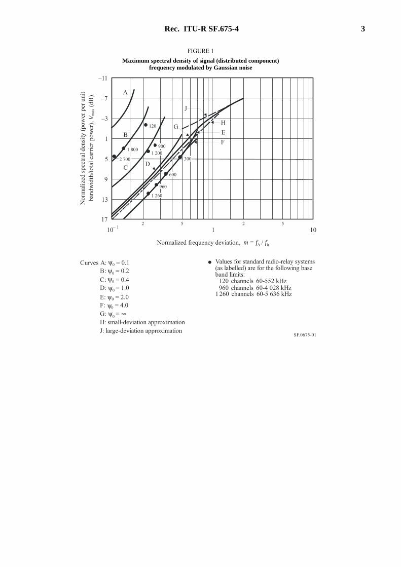
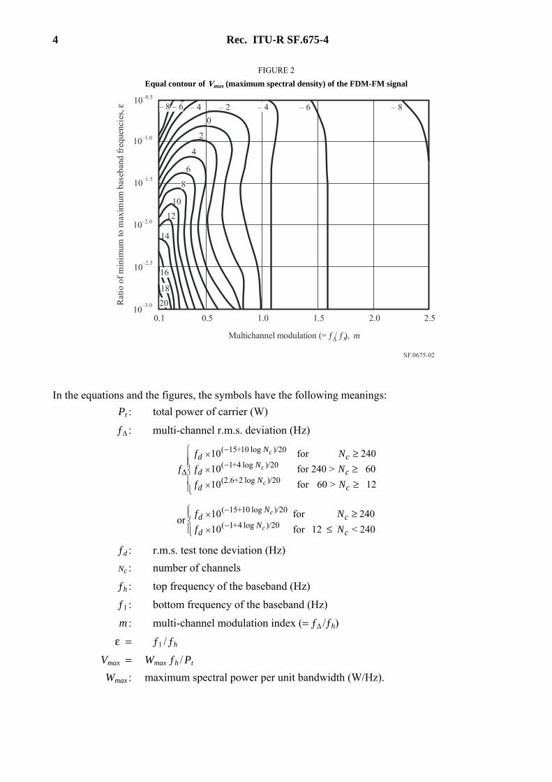
The maximum power of the spectral density in the continuous part of the spectrum can be obtained approximately from Figs 1 and 2.
Rec. ITU-R SF.675-4 3
FIGURE 1
Maximum spectral density of signal (distributed component) frequency modulated by Gaussian noise
SF.0675-01
C
120
2 700
1 800
D
900
1 200
G
J
A
B
600
300
960
1 260
H
E
F
–11
–7
–3
1
5
9
13
17
12 5
102 5
10– 1
Nor
mal
ized
spe
ctra
l den
sity
(po
wer
per
uni
tba
ndw
idth
/tot
al c
arri
er p
ower
),
(dB
)V
max
Normalized frequency deviation, m = f Δ / fh
Curves A: = 0.1B: = 0.2C: = 0.4D: = 1.0
E: = 2.0F: = 4.0G: = H: small-deviation approximationJ: large-deviation approximation
ψψψψψψψ ∞
0
0
0
0
0
0
0
Values for standard radio-relay systems(as labelled) are for the following baseband limits:
120 channels 60-552 kHz960 channels 60-4 028 kHz
1 260 channels 60-5 636 kHz
•
4 Rec. ITU-R SF.675-4
FIGURE 2
Equal contour of Vmax (maximum spectral density) of the FDM-FM signal
SF.0675-02
Multichannel modulation (= / ), ƒ ƒΔ h m
20
14
16
18
8
10
12
6
4
2
0
– 8– 6– 4– 2– 4– 6– 8
0.110
–3.0
10–2.5
10–2.0
10–1.5
10–1.0
10–0.5
0.5 1.0 1.5 2.0 2.5
Rat
io o
f m
inim
um to
max
imum
bas
eban
d fr
eque
ncie
s, ε
In the equations and the figures, the symbols have the following meanings:
Pt : total power of carrier (W)
ƒΔ : multi-channel r.m.s. deviation (Hz)
≥≥≥
×
−×
−×
Δ12>60for10
60>240for10
240for 10
)/20 log 2+(2.6
)/20 log 4+1(
)/20 log 10+15(
cN
d
cN
d
cN
d
Nf
Nf
Nf
fc
c
c
≤≥
−×
−×
240<12for10
240for10or )/20 log 4+1(
)/20 log 10+15(
cN
d
cN
d
Nf
Nfc
c
ƒd : r.m.s. test tone deviation (Hz)
Nc : number of channels
ƒh : top frequency of the baseband (Hz)
ƒ1 : bottom frequency of the baseband (Hz)
m : multi-channel modulation index (= ƒΔ /ƒh)
ε = ƒ1 / ƒh
Vmax = Wmax ƒh / Pt
Wmax : maximum spectral power per unit bandwidth (W/Hz).
Rec. ITU-R SF.675-4 5
For carriers for which 1 < N ≤ 12, the maximum power density per 4 kHz is approximated by the expression:
Pt cos2 mb
1.5mmmmmmW/4 kHzmmmmmmfor mb < 1 (6)
where:
Pt : total power of the carrier (W)
mb : peak modulation index (rad) due to a 0 dBm test tone in the highest frequency baseband channel.
1.2 FM carrier modulated by a multi-channel telephony signal and an energy dispersal signal of a triangular waveform with fixed amplitude
Triangular wave dispersal systems are normally designed to ensure that the maximum power spectral density per 4 kHz centred on the carrier frequency is maintained within 3 dB of the fully loaded value.
The power spectral density centred on the carrier frequency is given by:
4000×ΔF
Pt kHzW/4 (7)
where:
Pt : total power of the carrier (W)
ΔF : peak-to-peak frequency deviation due to the energy dispersal signal (Hz).
NOTE 1 – Equation (7) assumes the use of a perfectly linear triangular dispersal waveform.
1.3 FM carrier modulated by a television video signal
– For the case where an energy dispersal signal of a triangular waveform is superimposed on the video signal, the maximum power density per 4 kHz in the worst case is given by:
4000×ΔF
Pt kHzW/4 (8)
where:
Pt : total power of the carrier (W)
ΔF : peak-to-peak frequency deviation due to the energy dispersal signal (Hz).
NOTE 1 – Equation (8) assumes the use of a perfectly linear triangular dispersal waveform. Negligible error results from this assumption for current FM-TV transmissions.
– For the case where there is no modulation by video and energy dispersal signals, the maximum power density per 4 kHz in the worst-case is given by:
PtmmmmmmW/4 kHz
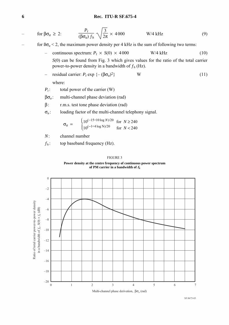
2 Phase modulated (PM) carrier modulated by a multi-channel telephony signal
When a PM carrier is modulated by a multi-channel telephony signal, the maximum power density is found at the centre frequency of the carrier. This is true if the top baseband frequency is much larger than the bottom baseband frequency. An expression for the maximum power density assuming this condition is given as follows:
6 Rec. ITU-R SF.675-4
– for βσa ≥ 2: Pt
(βσa) ƒh
32π × 4 000mmmmmmW/4 kHz (9)
– for ßσa < 2, the maximum power density per 4 kHz is the sum of following two terms:
– continuous spectrum: Pt × S(0) × 4 000mmmmmmW/4 kHz (10)
S(0) can be found from Fig. 3 which gives values for the ratio of the total carrier power-to-power density in a bandwidth of ƒh (Hz).
– residual carrier: Pt exp {– (βσa)2}mmmmmmW (11)
where:
Pt : total power of the carrier (W)
βσa : multi-channel phase deviation (rad)
β : r.m.s. test tone phase deviation (rad)
σa : loading factor of the multi-channel telephony signal.
σa =
<≥
−
−
240for10
240for10N)/20 log 4+1(
)/20 log 10+15(
N
NN
N : channel number
ƒh : top baseband frequency (Hz).
FIGURE 3
Power density at the centre frequency of continuous power spectrum of PM carrier in a bandwidth of fh
SF.0675-03
0
–2
–4
–6
–8
–10
–12
–14
–16
–18
–200 1 2 3 4 5 6 7
Multi-channel phase derivation, βσa (rad)
Rat
io o
f to
tal c
arri
er p
ower
-to-
pow
er d
ensi
tyin
a b
andw
idth
of
ƒ,
(0)
ƒ (
dB)
hS
×h
Rec. ITU-R SF.675-4 7
3 Digital carrier with necessary bandwidth greater than 4 kHz
The maximum power density per Hz of a digital carrier is given by:
Po = Pt/B (12)
where:
Pt : total power of the carrier (W)
B : necessary bandwidth of the digital emission (Hz).
The maximum power density per 4 kHz in the worst case is given by multiplying the result of equation (12) by 4 × 103 as:
P4 kHz = Po * 4 × 10³ (W/4 kHz) (13)
4 Digital carrier with necessary bandwidth less than 4 kHz
For those cases with multiple identical carriers with a bandwidth less than 4 kHz where it is known that any 4 kHz will not be completely filled with such carriers, the following equation should be applied:
P4 kHz = (Pt * N) (W/4 kHz) (14)
where:
Pt: total power of a single carrier (W)
N: maximum number of carriers, or portions of carriers, with a bandwidth less than 4 kHz to occupy any given 4 kHz band.
Equation (14) can be generalized for the case where it is known that there will be multiple different types of carriers with bandwidths less than 4 kHz occupying any given 4 kHz band by summing the power of the various individual carrier types to occupy the 4 kHz band and assuming this total power is the power per 4 kHz.
5 TT&C carrier
When narrow-band TT&C carriers are involved, in accordance with RR No. 1.23, in frequency bands below 15 GHz, care must be taken in assessing the maximum power per 4 kHz for such carriers. This is due to the fact that such carriers can have multiple distinct and significant spectral components. As such, it is important to consider the actual spectral shape of such TT&C carriers when selecting the worst 4 kHz bandwidth in order to assess the maximum power density.
8 Rec. ITU-R SF.675-4
Annex 2
Calculation of the maximum power density (averaged over 1 MHz) of a digital or TT&C carrier
Given below is the method of calculating the power level in the worst 1 MHz (W/MHz).
1 Digital carrier with necessary bandwidth greater than 1 MHz
The maximum power density per Hz of a digital carrier is given by:
Po = Pt /B (W/Hz) (15)
where:
Pt: total power of the carrier (W)
B: necessary bandwidth of the digital emission (Hz).
The maximum power density per MHz in the worst case is given by multiplying the result of equation (15) by 1 × 106 as:
P1 MHz = Po * 1 × 10⁶ (W/MHz) (16)
2 Digital carrier with necessary bandwidth less than 1 MHz
Note that for digital carriers with a necessary bandwidth less than 1 MHz, a determination must be made as to the maximum number of carriers, and portions of carriers, that will be operating in any 1 MHz band. Where this maximum number of carriers is not known, an assumption should be made that the 1 MHz reference bandwidth will be filled with multiple identical carriers. Under this assumption equations (15) and (16) provide the estimate of the maximum power density per MHz in the worst case. For those cases with carriers with a necessary bandwidth less than 1 MHz where it is known that any 1 MHz will not be completely filled with multiple identical carriers, the following equation for calculating the maximum power density per 1 MHz should be applied:
P1 MHz = (Pt * N) (W/MHz) (17)
where:
Pt: total power of a single carrier (W)
N: maximum number of carriers, including portions of carriers, with a necessary bandwidth less than 1 MHz to occupy any given 1 MHz band.
Equation (17) can be generalized for the case where it is known that there will be multiple different types of carriers with necessary bandwidths less than 1 MHz occupying any given 1 MHz band by summing the power of the various individual carrier types to occupy the 1 MHz band and assuming this total power is the power per 1 MHz.
3 TT&C carrier
When, in accordance with RR No. 1.23, narrow-band TT&C carriers are involved, the calculation of maximum power density per MHz can lead to an overestimation of the potential interference power. This is due to the fact that simply scaling the power of a single TT&C carrier up to 1 MHz by applying a ratio of the bandwidths would result in a power level greater than the TT&C carrier itself when a single TT&C carrier with a necessary bandwidth less than 1 MHz is used in a given frequency assignment. In such cases, the interference potential caused by a TT&C carrier would be
Rec. ITU-R SF.675-4 9
more accurately assessed if recognition were given to the fact that, in most cases, only a single TT&C carrier will be transmitted in any given 1 MHz band.
As such, the maximum power density per 1 MHz for a TT&C carrier having a necessary bandwidth less than 1 MHz is given by:
Pt (W/MHz) (18)
where:
Pt: total power of the TT&C carrier (W).
For the case of a TT&C carrier having a necessary bandwidth greater than 1 MHz, but not more than 1.5 MHz, the maximum power density per 1 MHz is given by:
Pt × (1 × 10⁶/B) (W/MHz) (19)
where:
Pt: total power of the TT&C carrier (W)
B: necessary bandwidth of the TT&C emission which is greater than 1 MHz (Hz).
______________