Embed Size (px)
Citation preview
UNITED NATIONS New York and Geneva, 2007
ECE/TRANS/SC.3/156/Rev.1
ECONOMIC COMMISSION FOR EUROPE INLAND TRANSPORT COMMITTEE
Working Party on Inland Water Transport
RECOMMENDATION ON ELECTRONIC CHART DISPLAY AND INFORMATION SYSTEM
FOR INLAND NAVIGATION (INLAND ECDIS)
Resolution No. 48 First Revised Edition
ECE/TRANS/SC.3/156/Rev.1 page 2
RECOMMENDATION ON ELECTRONIC CHART DISPLAY AND INFORMATION SYSTEM FOR INLAND NAVIGATION
(INLAND ECDIS)
Resolution No. 48
adopted by the Working Party on Inland Water Transport on 25 October 2001
The Working Party on Inland Water Transport,
Noting the development of electronic charts for inland navigation and the necessity to have a harmonized standard for these charts in Europe to enable international transport to use charts of different countries with the same equipment of hardware and software,
Bearing in mind the existing standard of IHO and IMO for Electronic Chart Display and Information Systems (S-52 and S-57) for maritime navigation and the desirability of compatibility in areas of mixed traffic, where inland navigation as well as seagoing vessels are navigating,
1. Recommends Governments, intergovernmental organizations, regional economic integration organizations, river commissions and private entities to apply the Inland ECDIS Standard reproduced in the annex to this resolution for the production of electronic charts for inland navigation,
2. Recommends Governments to bring their national legislation concerning navigation by inland waterway in accordance with the Inland ECDIS Standard,
3. Invites Governments to keep the secretariat informed of the measures taken with a view to the introduction of the Inland ECDIS Standard, specifying the inland waterways concerned,
4. Requests the Executive Secretary of the Economic Commission for Europe to periodically include the question of application of this resolution in the agenda of the Working Party on Inland Water Transport.
ECE/TRANS/SC.3/156/Rev.1 page 3 Annex
Annex
Electronic Chart Display and Information System for Inland Navigation (Inland ECDIS) 1/
Contents Page
Preface ................................................................................................................................ 4 Structure of the Inland ECDIS Standard ............................................................................ 6 Comparison of the structures of the standards for (Maritime) ECDIS and Inland ECDIS . 7
Section 1 Performance standard ........................................................................ 9 Section 2 Data standard for Inland ENCs .......................................................... 20 Section 2a Codes for Producers and Waterways.................................................. 22 Section 3 Presentation standard for Inland ECDIS ............................................ 24 Section 4 Operational and Performance Requirements, Methods of Testing and Required Test Results ................................. 28
Appendix A: Measures to ensure software quality ............................ 42 Appendix B: System configurations .................................................. 49
Section 5 Glossary of terms ............................................................................... 51 Appendix 2/ Status of Product Specification for Inland ENCs including - Status of Inland ENC Feature Catalogue and - Status of Inland ENC Encoding Guide
Status of Codes for Producers and Waterways Status of Presentation Library for Inland ECDIS including - Status of Look-up Tables - Status of Symbols - Status of Conditional Symbology Procedures
1/ The text of the annex has been brought in line with the latest proposal (Edition 2.0) of the Inland ECDIS Expert Group of 23.11.2006, also accepted by the CCNR. 2/ The text of the appendix is not enclosed to the document. It can be found on the website of the UNECE Working Party on Inland Water Transport “http://www.unece.org/trans/main/sc3/sc3/sc3fdoc.html”
ECE/TRANS/SC.3/156/Rev.1 page 4 Annex
Electronic Chart Display and Information System for Inland Navigation (Inland ECDIS)
Preface
Since the late nineties of the last century reflections and experiments have been made in several UNECE member states to use telematics for the support of inland navigation. In different research and development projects the radar image on the display in the skipper's wheelhouse was underlaid by an electronic chart. This is an approach to higher safety and more efficiency of inland navigation.
The discussions established that only an internationally agreed procedure would be successful, since a skipper could not be expected to employ different equipment in each country. This was the reason why the internationally introduced and well matured Electronic Chart Display and Information System (ECDIS) - originally developed for maritime navigation - was also considered for inland navigation. The idea was to adopt ECDIS for inland navigation and to supplement some distinct inland features, but not to change the original ECDIS standard. In this way, it was possible to have compatibility between the original - Maritime - ECDIS and Inland ECDIS. This is important for the estuaries of the rivers, where sea vessels as well as inland vessels navigate.
In 1998 the European Union (EU) appointed an Inland ECDIS Expert Group for the development of an Inland ECDIS Standard. The Expert Group submitted its first proposal on 1 January 1999.
In the year 2000, the competent committees of the Central Commission for the Navigation on the Rhine (CCNR) in Strasbourg installed an Ad-hoc Working Group for Inland ECDIS with the order to draft the Inland ECDIS Standard of CCNR.
The Ad-hoc Working Group started with the results of the Expert Group as the basis for their further work and elaborated edition 1.0 of the Inland ECDIS Standard. The Inland ECDIS standards has been adopted not only by CCNR, but also by the Danube Commission, the UNECE and International Navigation Association (PIANC) and has become the first standard in the area of inland navigation, which has been recognized by all these organizations.
The further development into edition 2.0 was driven by several aspects:
• The research and development project COMPRIS (Consortium Operational Management Platform River Information Services) of the European Union did further development of the Inland ECDIS Standard and Inland ECDIS based applications. These developments have been focused on the information side of Inland ECDIS with special regard to voyage planning.
• As the Inland ECDIS Standard has not been officially recognised by International Hydrographic Organization (IHO) so far, there are already some incompatibilities between edition 3.1 of S-57 and the Inland ECDIS Standard. In order to ensure the future compatibility of Inland ECDIS and S-57 and its foreseen successors S-100 and S-101 it is
ECE/TRANS/SC.3/156/Rev.1 page 5 Annex
necessary to obtain full recognition by IHO. Therefore a harmonization group with the United States of America and some companies from Canada has been set up to get a better basis for a worldwide recognition of Inland ECDIS. The Inland ENC Harmonization Group (IEHG) has received a mandate as a task force of the Inland ECDIS expert group. The Russian Federation has joined the harmonization group in 2004. IEHG developed an Inland ENC Encoding Guide on the basis of a similar document of the US Army Corps of Engineers (USACE). This document was amended with the additional features and attributes of the European approach after a thorough check was run on which features and attributes to introduce. Whenever possible, the American approach of using pure S-57 to encode the same real world entities was applied. All the amendments of COMPRIS and the harmonization process were introduced in the documents of the Inland ECDIS standard by the Inland ECDIS Expert Group.
• The European Directive 2005/44/EC of 7 September 2005 “on harmonised river information services (RIS) on inland waterways in the Community” requires the adoption of a technical specification in the area of Inland ECDIS in October 2006.
The Inland ECDIS Expert Group has delivered its proposal for edition 2.0 in June 2006 to the relevant international organizations for adoption.
Based on this proposal from the group, the UNECE Working Party on Inland Water Transport (SC.3) at its 50th session, decided to update its Resolution No. 48 on Inland ECDIS accordingly (ECE/TRANS/SC.3/174 paragraph 50).
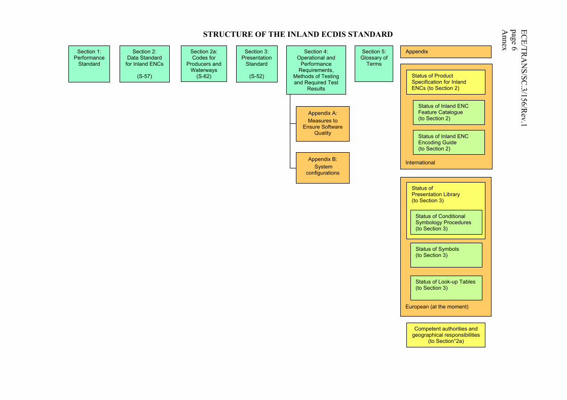
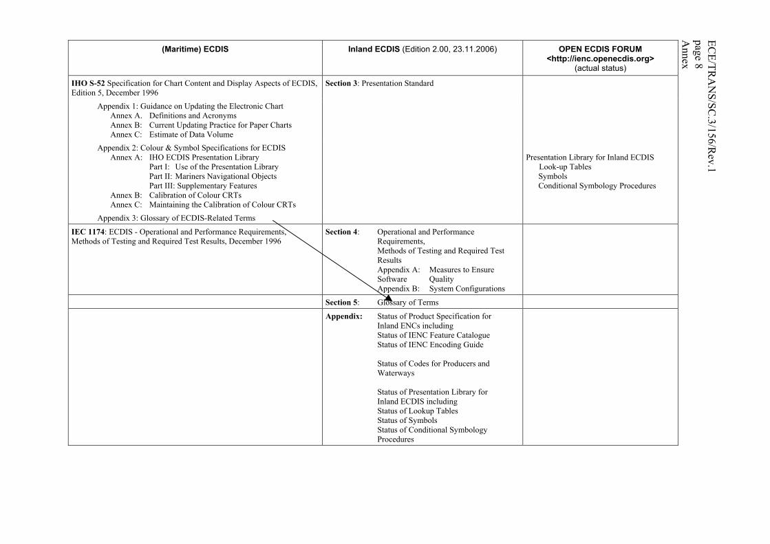
The following diagram and the table show, respectively, the structure of the Inland ECDIS and the mapping between (maritime) ECDIS and the Inland ECDIS Standard, Edition 2.0.
Technical annexes and appendixes established by the Expert Group on Inland ECDIS can be consulted in English and French at the website of the Working Party on Inland Water Transport: “http://www.unece.org/trans/main/sc3/sc3/sc3fdoc.html”.
ECE/TR
AN
S/SC.3/156/R
ev.1page 6 A
nnex
STRUCTURE OF THE INLAND ECDIS STANDARD
Appendix B: System
configurations
Section 1: Performance
Standard
Section 2: Data Standard
for Inland ENCs
(S-57)
Section 2a: Codes for
Producers and Waterways
(S-62)
Section 3: Presentation
Standard
(S-52)
Section 4: Operational and
Performance Requirements,
Methods of Testing and Required Test
Results
Appendix A: Measures to
Ensure Software Quality
Section 5:Glossary of
Terms
Appendix
International
Status of Product Specification for Inland ENCs (to Section 2)
Status of Inland ENC Feature Catalogue (to Section 2)
Status of Inland ENC Encoding Guide (to Section 2)
European (at the moment)
Status of Presentation Library (to Section 3)
Status of Conditional Symbology Procedures(to Section 3)
Status of Symbols (to Section 3)
Status of Look-up Tables(to Section 3)
Competent authorities and geographical responsibilities
(to Section°2a)

ECE/TR
AN
S/SC.3/156/R
ev.1page 7 A
nnex COMPARISON OF THE STRUCTURES OF THE STANDARDS FOR (MARITIME) ECDIS AND INLAND ECDIS
(Maritime) ECDIS Inland ECDIS (Edition 2.00, 23.11.2006) OPEN ECDIS FORUM <http://ienc.openecdis.org>
(actual status)
IMO A.817(19) Performance Standards for ECDIS, November 1995 Appendix 1: Reference Documents Appendix 2: SENC Information Appendix 3: Navigational Elements and Parameters Appendix 4: Areas for which special conditions exist Appendix 5: Alarms and Indicators
Section 1: Performance Standard
IHO S-57: Transfer Standard for Digital Hydrographic Data, Edition 3.1, November 2000
Section 2: Data Standard for Inland ENCs
Part 1: General Introduction Part 2: Theoretical Data Model Part 3: Data Structure
Appendix A: IHO Object catalogue Introduction Chapter 1: Object Classes Chapter 2: Attributes
Annex B: Attributes/Object Classes Cross Reference
Inland ENC Feature Catalogue
Appendix B: Product specifications Appendix B.1: ENC Product Specification Annex A: Use of The Object Catalogue for ENC Annex B: Example of CRC Coding Appendix B.2: IHO Object Catalogue Data Dictionary Product Specification
Product Specification for Inland ENCs IENC Encoding Guide
IHO S-62 ENC Producer Codes, Edition 2.2, March 2006 Section 2a: Codes for Producers and Waterways Competent authorities and geographical responsibilities OEF (<https://www.openecdis.org>): Codes for Producers and Waterways (not part of the Inland ECDIS Standard)
ECE/TR
AN
S/SC.3/156/R
ev.1page 8 A
nnex
(Maritime) ECDIS Inland ECDIS (Edition 2.00, 23.11.2006) OPEN ECDIS FORUM <http://ienc.openecdis.org>
(actual status)
IHO S-52 Specification for Chart Content and Display Aspects of ECDIS, Edition 5, December 1996
Section 3: Presentation Standard
Appendix 1: Guidance on Updating the Electronic Chart Annex A. Definitions and Acronyms Annex B: Current Updating Practice for Paper Charts Annex C: Estimate of Data Volume
Appendix 2: Colour & Symbol Specifications for ECDIS Annex A: IHO ECDIS Presentation Library Part I: Use of the Presentation Library Part II: Mariners Navigational Objects Part III: Supplementary Features Annex B: Calibration of Colour CRTs Annex C: Maintaining the Calibration of Colour CRTs
Presentation Library for Inland ECDIS Look-up Tables Symbols Conditional Symbology Procedures
Appendix 3: Glossary of ECDIS-Related Terms
IEC 1174: ECDIS - Operational and Performance Requirements, Methods of Testing and Required Test Results, December 1996
Section 4: Operational and Performance Requirements,
Methods of Testing and Required Test Results
Appendix A: Measures to Ensure Software Quality
Appendix B: System Configurations
Section 5: Glossary of Terms
Appendix: Status of Product Specification for Inland ENCs including Status of IENC Feature Catalogue Status of IENC Encoding Guide Status of Codes for Producers and
Waterways Status of Presentation Library for Inland ECDIS including Status of Lookup Tables Status of Symbols Status of Conditional Symbology
Procedures
ECE/TRANS/SC.3/156/Rev.1 page 9 Annex
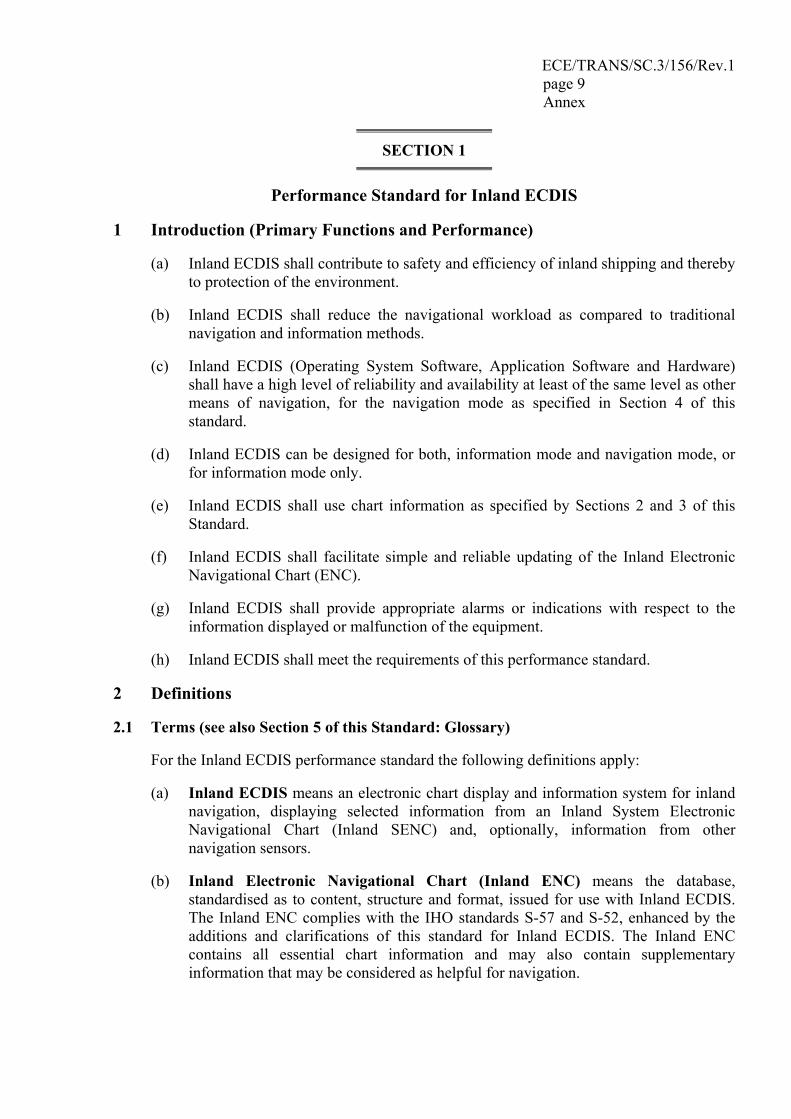
SECTION 1
Performance Standard for Inland ECDIS
1 Introduction (Primary Functions and Performance)
(a) Inland ECDIS shall contribute to safety and efficiency of inland shipping and thereby to protection of the environment.
(b) Inland ECDIS shall reduce the navigational workload as compared to traditional navigation and information methods.
(c) Inland ECDIS (Operating System Software, Application Software and Hardware) shall have a high level of reliability and availability at least of the same level as other means of navigation, for the navigation mode as specified in Section 4 of this standard.
(d) Inland ECDIS can be designed for both, information mode and navigation mode, or for information mode only.
(e) Inland ECDIS shall use chart information as specified by Sections 2 and 3 of this Standard.
(f) Inland ECDIS shall facilitate simple and reliable updating of the Inland Electronic Navigational Chart (ENC).
(g) Inland ECDIS shall provide appropriate alarms or indications with respect to the information displayed or malfunction of the equipment.
(h) Inland ECDIS shall meet the requirements of this performance standard.
2 Definitions
2.1 Terms (see also Section 5 of this Standard: Glossary)
For the Inland ECDIS performance standard the following definitions apply:
(a) Inland ECDIS means an electronic chart display and information system for inland navigation, displaying selected information from an Inland System Electronic Navigational Chart (Inland SENC) and, optionally, information from other navigation sensors.
(b) Inland Electronic Navigational Chart (Inland ENC) means the database, standardised as to content, structure and format, issued for use with Inland ECDIS. The Inland ENC complies with the IHO standards S-57 and S-52, enhanced by the additions and clarifications of this standard for Inland ECDIS. The Inland ENC contains all essential chart information and may also contain supplementary information that may be considered as helpful for navigation.
ECE/TRANS/SC.3/156/Rev.1 page 10 Annex
(c) Inland System Electronic Navigational Chart (Inland SENC) means a database, resulting from the transformation of the Inland ENC by Inland ECDIS, for appropriate use, updates to the Inland ENC by appropriate means and other data added by the skipper. It is this database that is actually accessed by the Inland ECDIS for display generation and other navigational functions. The Inland SENC may also contain information from other sources.
(d) Minimum Information Density (display base) means the minimum amount of SENC information that is presented and which cannot be reduced by the operator, consisting of information that is required at all times in all geographic areas and under all circumstances.
(e) Standard Information Density (standard display) means the default amount of SENC information that shall be visible when the chart is first displayed on Inland ECDIS first.
(f) All Information Density (all display) means the maximum amount of SENC information. Here, in addition to the standard display, also all other features are displayed, individually on demand.
(g) User-defined settings means the possibility to use and store a profile of display and operation controls-settings.
(h) Integrated Display means a head-up, relative-motion picture consisting of the SENC overlaid with the radar-image with matching scale, offset and orientation.3/
(i) Navigation Mode means the use of the Inland ECDIS for conning the vessel with overlaid radar image.4/
(j) Information Mode means the use of the Inland ECDIS for information purposes only without overlaid radar image.5/
3/ On wide inland waterways Basin Administration may allow the true motion and north-up orientation of the picture. 4/ On wide inland waterways, Basin Administration may waive the requirement concerning the differentiation between the ‘Navigation Mode” and “Information Mode” of usage of Inland ECDIS, just as it is the case in the IMO Standard S52. 5/ On wide inland waterways, Basin Administration may waive the requirement concerning the differentiation between the ‘Navigation Mode” and “Information Mode” of usage of Inland ECDIS, just as it is the case in the IMO Standard S52.
ECE/TRANS/SC.3/156/Rev.1 page 11 Annex
2.2 References
(a) IHO Special Publication No. S-57, "IHO Transfer Standard for Digital Hydrographic Data", Edition 3.1, November 2000
(b) IHO Special Publication No. S-62, "ENC Producer Codes", Edition 2.2, March 2006
(c) IHO Special Publication No. S-52, "Specifications for Chart Content and Display Aspects of ECDIS", 5th Edition, December 1996, including:
• S-52 Appendix 1 "Guidance on Updating the Electronic Chart", 3rd Edition, July 1997
• S-52 Appendix 2 "Colour and Symbols Specifications for ECDIS", Edition 4.2, March 2004, and
• S-52 Appendix 3 "Glossary of ECDIS-related Terms", 3rd Edition, December 1997
(d) IMO Resolution A.817(19), "Performance Standards for Electronic Chart Display and Information Systems (ECDIS)", November 1995
(e) IEC-Guideline 1174, "ECDIS - Operational and performance requirements, methods of testing and required test results", December 1996
(f) CCNR resolutions 1989-II-33, 34 and 35, “Minimum requirements, test conditions, installation and performance testing of radar equipment and rate-of-turn indicators for Rhine navigation”, version of 1.1.2004
(g) DC “Recommendations on the main technical and operational parameters for the radar installations used for the navigation on the Danube”, CD/SES 60/10, Budapest, 2003
(h) UNECE Resolution No. 54, “Additions and amendments to resolution No. 24 on CEVNI: European Code for Inland Waterways”, Annex 10, “General Technical Specifications applicable to radar equipment”, TRANS/SC.3/115/Rev.2/Amend.1
(i) UNECE Resolution No. 57, “Guidelines and Recommendations for River Information Services”, TRANS/SC.3/165, October 2004
3 Contents, Provision and Updating of Chart Information
3.1 Contents and Provision of Inland ENCs
(a) The chart information to be used in Inland ECDIS shall be the latest edition of information.
(b) Provisions shall be made to prevent the user from altering the contents of original Inland ENC editions.
ECE/TRANS/SC.3/156/Rev.1 page 12 Annex
(c) If the chart is intended to be used for navigation mode (Ch. 5.2), at least the following features shall be included in the ENC:
• bank of waterway (at mean water level) • shoreline construction (e.g. groyne, longitudinal control dam, training wall –
any facility that is considered a hazard to navigation) • contours of locks and dams • boundaries of the fairway / navigation channel (if defined) • isolated dangers in the fairway / navigation channel under water • isolated dangers in the fairway / navigation channel above water level, such as
bridges, overhead cables etc. • official aids-to-navigation (e.g. buoys, beacons, lights, notice marks) • waterway axis with kilometres and hectometres or miles
(d) If the chart is intended to be used for navigation mode (Ch. 5.2), the respective competent authority decides for each waterway or harbour which of the above named features are to be verified. (Recommendation: the whole minimum content of an Inland ENC should be verified.) The respective competent authority shall declare which Inland ENCs are appropriate to navigation mode within its geographic responsibility. (For details see section 2a of this Standard.)
3.2 Updates
(a) Inland ECDIS shall be capable of accepting updates to the Inland ENC data provided in conformity with the agreed standards. These updates shall be applied to the SENC automatically. The implementation procedure shall not interfere with the display in use.
(b) Inland ECDIS shall allow display of updates, so that the skipper may review their contents and ascertain that they have been included in the SENC.
(c) Inland ECDIS shall be capable of revoking automatically applied updates of the Inland ENC data.
(d) Original Inland ENC editions and later updates shall never be merged.
(e) The Inland ENC and all updates to it shall be displayed without any degradation of their information content.
(f) The Inland ENC data and updates to it shall be clearly distinguishable from other information.
(g) Inland ECDIS shall ensure that the Inland ENC and all updates to it have been correctly loaded into the SENC.
(h) Inland ECDIS shall keep a record of updates, including the time of application to the SENC.
(i) The contents of the SENC to be used shall be adequate and up to date for the intended voyage.
ECE/TRANS/SC.3/156/Rev.1 page 13 Annex
4 Presentation of Information
4.1 Display Requirements
(a) The display method shall ensure that the displayed information is clearly visible to more than one observer in the typical conditions of light experienced in the wheelhouse of a vessel by day and night.
(b) The display size of the chart presentation shall be at least 270 mm by 270 mm for equipment designed and admitted for the Navigation Mode. In Information Mode ergonomic aspects shall determine the size.
(c) The display requirements shall be met whether in landscape or in portrait format.
4.2 Display Ranges (Scales)
(a) In Information Mode (ref. to Ch. 5.1), it is recommended to use the same ranges as specified in the Navigation Mode.
(b) In Navigation Mode (ref. to Ch. 5.2), only the successive switchable ranges (scales) specified in Section 4, Ch. 4.7 of this Standard are allowed.
4.3 Image Positioning and Orientation
(a) In Information Mode all kinds of chart orientation are allowed (see Ch. 5.1)
(b) In Navigation Mode the chart shall be automatically positioned and oriented in the relative motion, head-up orientation with the own ship’s position in the screen centre or off-centred (see Ch. 5.2).6/
4.4 Display of SENC Information
(a) The display of SENC information shall be divided into the following three display categories:
• Display Base • Standard Display • All Display
The membership of the feature classes in the display categories is given in detail in the Look-up Tables of IHO S-52, Appendix 2, Annex A (Presentation Library) and in the “Presentation Library for Inland ECDIS” (see Look-up Tables), which is published at <http://ienc.openecdis.org>.
6/ See footnote to subparagraph 2.1(h).
ECE/TRANS/SC.3/156/Rev.1 page 14 Annex
(b) The Display Base category has to contain at least the following features:
• bank of waterway (at mean water level) • shoreline construction (e.g. groyne, longitudinal control dam, training wall –
any facility that is considered a hazard to navigation ) • contours of locks and dams • boundaries of the fairway / navigation channel (if defined) • isolated dangers in the fairway / navigation channel under water • isolated dangers in the fairway / navigation channel above water level, such as
bridges, overhead wires etc. • official aids-to-navigation (e.g. buoys, lights and beacons)
(c) The Standard Display category has to contain at least the following features:
• the objects of Display Base category • prohibited and restricted areas • piers for commercial vessels (cargo and passenger) • kilometre and hectometre or mile marks on the banks
(d) The All Information Display category has to display all features that are contained in the Inland SENC, individually on demand.
(e) When invoking the Inland ECDIS, it shall come up with the Standard Information Density at an appropriate range available in the SENC for the displayed area
(f) Inland ECDIS shall be switchable to the Standard Information Density at any time by a single operator action.
(g) Inland ECDIS shall clearly indicate the information density currently in use at all times.
(h) Time variable depth information in the ENC has to be displayed independently of the above named three display categories.
4.5 Display of Radar Information
(a) In Navigation Mode the radar image shall have the highest display priority and it is only allowed to be presented in the relative motion, head-up mode. If the system is also type approved for maritime ECDIS, true motion and north-up mode may be implemented. If such a system is used in true motion and/or north-up mode on European inland waterways, it is considered to be working in Information Mode.
(b) The under laid SENC shall match in position, range and orientation. The radar image and the position from the position sensor shall both be adjustable for the antenna offset to the conning position.
(c) The overlaid radar image has to conform to the minimum requirements as specified in Section 4, Ch. 4.14 of this Standard.
ECE/TRANS/SC.3/156/Rev.1 page 15 Annex
(d) The overlaid radar-image may contain additional navigational information. Any additional navigational information and tracking and tracing symbols should however in no way degrade the display of the original radar content.
4.6 Display of Other Navigational Information
(a) Inland ECDIS and additional navigational information shall use a common reference system.
(b) It shall be possible to display the skipper's own ship's position on the screen.
(c) It shall be possible for the skipper to select safety limits.
(d) Inland ECDIS shall emphasize the falling short of the safety limits.
4.7 Colours and Symbols
(a) The display of colours and symbols to represent SENC information shall at least be able to comply with the regulations of Section 3 of this Standard. Additionally other user-selectable symbol sets are allowed.
(b) To present navigational elements and parameters as listed in the IMO Resolution A.817(19), Appendix 3 other colours and symbols than those mentioned in 4.7.a must be used.
4.8 Data and Display Accuracy
(a) The accuracy of the calculated data that are presented shall be independent of the display characteristics and shall be consistent with the SENC accuracy.
(b) The Inland ECDIS shall provide an indication whether the display uses a smaller display range than the accuracy of the Inland ENC data offers (over-scale indication).
(c) The accuracy of all calculations performed by Inland ECDIS shall be independent of the characteristics of the output device and shall be consistent with the SENC accuracy.
(d) Bearings and distances drawn on the display or those measured between features already drawn on the display shall have an accuracy no less than that afforded by the resolution of the display.
ECE/TRANS/SC.3/156/Rev.1 page 16 Annex
5 Operation
5.1 Information Mode
(a) Information Mode is intended to be used for information only and not for navigation.
(b) In Information Mode all kinds of chart orientation, rotation, zooming and panning are allowed. However, it is recommended to use the same fixed ranges as in the Navigation Mode and the chart orientation either
• to north, or • to the fairway axis at the actual position, or • to the actual ships-heading.
(c) It should be possible to scroll the chart manually on the screen with the fairway axis in line with the vertical screen axis.
(d) Inland ECDIS may be connected to a positioning sensor to scroll the chart picture automatically and to display the section of chart matching the actual surrounding, namely in the operator-selected range.
(e) It is recommended to only display information regarding the position and orientation of other vessels, gathered by communication links like AIS or AI-IP, if they are up-to-date (nearly real-time) and accurate. The presentation of the position and the orientation of other vessels by
• a directed triangle or • a true outline (to scale)
are strongly discouraged if the heading of these other vessels is not available. A generic symbol is recommended.
5.2 Navigation Mode
(a) In Navigation Mode, the Inland ECDIS display shall be integrated with the own ship's radar information. The radar information shall be clearly distinguishable from the SENC information.
(b) The integrated display must be in accordance with the requirements for radar on inland waterways as specified in Section 4, Ch. 4.14 of this Standard.
(c) The chart and the radar image must match in size, position and orientation within the limits as specified in Section 4, Ch. 3.4 and 8.3.2 of this Standard.
ECE/TRANS/SC.3/156/Rev.1 page 17 Annex
(d) The Integrated Display shall only be presented in the head-up orientation. Other orientations are permitted in systems with an additional maritime ECDIS type approval. If such a system is used in true motion and/or north-up mode on European inland waterways, it is considered to be working in Information Mode.7/
(e) It shall be possible for the operator to adjust the displayed position of the vessel so that the radar image matches the SENC display.
(f) It shall be possible to remove either the ECDIS or the radar information by a single operator action temporarily.
(g) The vessel’s position shall be derived from a continuous positioning system of which the accuracy is consistent with the requirements of safe navigation.
(h) Navigation Mode must provide an indication when the input from the position-fixing system is lost. Navigation Mode shall also repeat, but only as an indication, any alarm or indication passed to it from a position fixing system.
(i) The positioning system and the SENC shall be based on the same geodetic datum.
(j) In navigation mode, the data according to Ch. 3.1.c of this standard shall always be visible and shall not be obscured by other objects.
(k) Information regarding the position and orientation of other vessels, gathered by other communication links than the own radar, are permitted to be displayed only if they are up-to-date (nearly real-time) and meet the accuracy that is required for the support of tactical and operational navigation.
(l) As tracking and tracing information (for example AIS) of other vessels is useful for the planning of the passing, but of no use during passing itself, T&T (AIS) symbols shall not disturb the radar image during passing and shall be faded out therefore. Preferably the application should allow the skipper to define the area where the symbol is faded out.
(m) The presentation of the position and the orientation of other vessels by
• a directed triangle or • a true outline (to scale)
(n) are permitted only if the heading of these other vessels is available. In all other cases a generic symbol shall be used (a square is recommended, a circle should be used for inland applications only).
7/ See footnote to subparagraph 2.1(h).
ECE/TRANS/SC.3/156/Rev.1 page 18 Annex
5.3 Operation and Control Elements
(a) Inland ECDIS shall be designed following ergonomic principles for user-friendly operation.
(b) The Inland ECDIS equipment shall have a minimum of operation and control elements (see Section 4).
(c) Operation and control elements, and indicators for connected sensors, may be integrated in Inland ECDIS.
(d) Standard settings and user-defined settings shall be retrievable easily.
6 Connections with other Equipment
(a) Inland ECDIS shall not affect the performance of any connected equipment adversely. Similarly the connection of optional equipment shall not degrade the performance of Inland ECDIS.
(b) Inland ECDIS shall be capable of generating information to other systems, e.g. for the purpose of electronic reporting.
(c) The relevant requirements of controls and indicators to connected equipment shall be fulfilled.
7 Indications and Alarms
7.1 Built-in Test Equipment (BITE)
Inland ECDIS shall be provided with means for carrying out on board tests of major functions either automatically or manually. In case of a failure, the module at fault shall be shown.
7.2 Malfunctions
Inland ECDIS shall provide a suitable alarm or indication of system malfunctions (ref. to Section 4, Ch. 9).
ECE/TRANS/SC.3/156/Rev.1 page 19 Annex
8 Fallback Arrangements
8.1 Insufficient accuracy of the SENC-positioning
In Navigation Mode the SENC shall be automatically switched off, if the SENC positioning does not match the radar picture within the limits of Section 4, Ch. 5.1 and 5.2. 8/
8.2 Defects
(a) If the Inland ECDIS system has an evident defect, it shall provide a suitable alarm (ref. to Section 4, Ch. 4.16 and 9 of this Standard).
(b) Facilities enabling a safe take-over of the Inland ECDIS functions shall be provided in order to ensure that an Inland ECDIS failure does not result in a critical situation.
9 Power Supply in Navigation Mode
(a) The Inland ECDIS shall have its own separate fused power supply.
(b) Interruptions of the power supply for a period up to 5 minutes shall not have any influence on correct operation and shall not require restarting of the equipment manually.
10 Maintenance
This section of this edition 2.0 of the standard will be updated by means of the following two documents:
Clarifications Document This contains improvements to the wording of the standard. These are editorial amendments, which do not result in any substantive change to the standard.
Corrections and Extensions Document This contains changes to the standard to correct factual errors and to make necessary amendments or extensions to the standard.
8/ On wide inland waterways Basin Administration may prescribe that Inland ECDIS shall provide a suitable alarm and/or indication, if the SENC positioning does not match the radar picture within the limits of Section 4, Ch. 5.1 and 5.2.
ECE/TRANS/SC.3/156/Rev.1 page 20 Annex
SECTION 2
Data Standard for Inland ENCs
Data Standard
1 Scope
This “Data Standard for Inland ENCs” describes the standard to be used
• for the exchange of digital hydrographic data between national inland waterway authorities and
• for its distribution to manufacturers, skippers and other users.
This Data Standard shall be used for the production of Inland ENCs. The transfer and distribution has to take place in such a way that none of the information is lost.
This Data Standard is based on the “IHO Transfer Standard for Digital Hydrographic Data”, Special Publication No. 57, Edition 3.1 with all Appendices and Annexes (see comparison table in the preface of this Inland ECDIS Standard), in brief "S-57".
This Data Standard describes the necessary additions and clarifications to S-57 and the application of S-57 for the purpose of use in Inland ECDIS applications.
2 Theoretical data model
The description of the theoretical data model as contained in S-57 Part 2 applies to the theoretical data model of Inland ENCs without any changes or amendments.
3 Data Structure
The description of the data structure as contained in S-57 Part 3 applies to the data structure of Inland ENCs without any changes or amendments.
4 Product Specification
The Inland ENC Product Specification is a set of specifications intended to enable chart producers to produce a consistent Inland ENC, and manufacturers to use that data efficiently in an Inland ECDIS that satisfies the Performance Standard for Inland ECDIS (Section 1).
An Inland ENC must be produced in accordance with the rules defined in this Specification and must be encoded using:
• the Inland ENC Feature Catalogue and • the rules described in the Inland ENC Encoding Guide.
ECE/TRANS/SC.3/156/Rev.1 page 21 Annex
The up-to-date Inland ENC Product Specification and its annexes are published at <http://ienc.openecdis.org>. Appendix A to this resolution contains the status quo of the Inland ENC Product Specification and its annexes at the moment of adoption of this edition of the standard.
Official Inland ENCs have to be produced in accordance with the latest version of the standard and the Product Specification at <http://ienc.openecdis.org>. Official Inland ENCs, which have been produced in accordance with Edition 1.02 of the Inland ECDIS Standard (also published at <http://ienc.openecdis.org>) before the entry into force of this standard remain valid until new editions are published in accordance with Edition 2.0.
5 Definitions
Definitions of terms may be found in
• S-57, part 1, clause 5 • the "Glossary of ECDIS Related Terms" in Appendix 3 to S-52 • the "Glossary of Terms" in Section 5 of this standard.
6 Maintenance
This section of this edition 2.0 of the standard will be updated by means of the following two documents:
Clarifications Document This contains improvements to the wording of the standard. These are editorial amendments, which do not result in any substantive change to the standard.
Corrections and Extensions Document This contains changes to the standard to correct factual errors and to make necessary amendments or extensions to the standard.
These documents, and the associated maintenance mechanism, do not apply to the Product Specification for Inland ENC (including its annexes). The maintenance procedure for the Product Specification for Inland ENC (including its annexes) is described in the Product Specification and its annexes.
ECE/TRANS/SC.3/156/Rev.1 page 22 Annex
SECTION 2a
Inland ECDIS Data Standard:
Codes for Producers and Waterways in addition to IHO–S-62 ENC Producer Codes
Codes for producers of Inland ENCs as well as the registration procedure are published at <http//www.openecdis.org>.
If administrations or private companies decide to produce Inland ENCs, they shall register a producer code at the “Open ECDIS Forum” at <http//www.openecdis.org>, if they are not already mentioned in IHO S-62.
Since a producer code alone is not sufficient in order to judge whether an Inland ENC is appropriate to navigation mode the following declaration process shall apply:
1. The respective competent authority for a waterway or a harbour shall register itself on the official websites of the organizations which have adopted this Standard. Details on the name of the authority, its geographical responsibility, its official website and other communication possibilities shall be given and shall be accessible on this website.
2. The respective competent authority for a waterway or a harbour shall maintain a list of Inland ENCs which are appropriate to navigation mode within its geographical responsibility. The list shall include the file name of the cell, which stretch of the inland waterway is covered, the edition number, the issue date and a list of available updates files to the currently valid edition, also with their issue dates. By putting an Inland ENC on that list the authority declares this cell as verified concerning the minimum content and therefore appropriate to navigation mode.
The lists of competent authorities for waterways or harbours with the abovementioned details on the official websites of the organizations which have adopted this Standard are regarded as digital parts of the Inland ECDIS Standard and are named “Competent authorities and geographical responsibilities”.
ECE/TRANS/SC.3/156/Rev.1 page 23 Annex
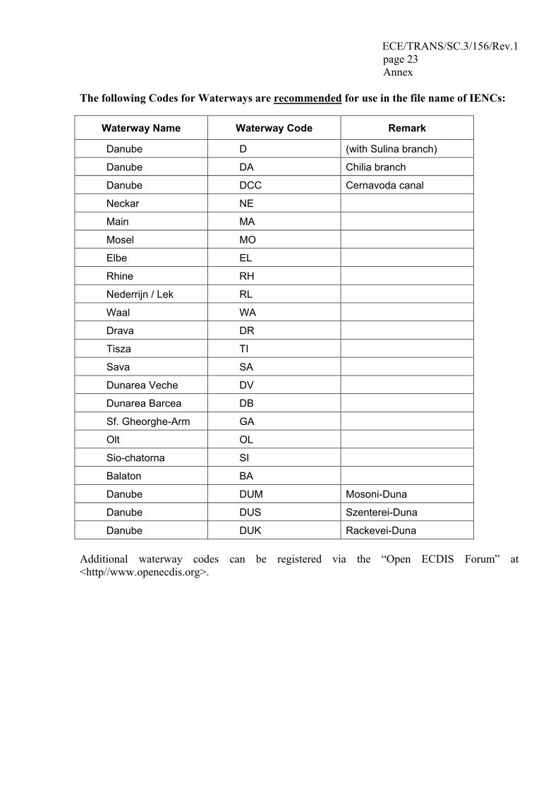
The following Codes for Waterways are recommended for use in the file name of IENCs:
Waterway Name Waterway Code Remark
Danube D (with Sulina branch)
Danube DA Chilia branch
Danube DCC Cernavoda canal
Neckar NE
Main MA
Mosel MO
Elbe EL
Rhine RH
Nederrijn / Lek RL
Waal WA
Drava DR
Tisza TI
Sava SA
Dunarea Veche DV
Dunarea Barcea DB
Sf. Gheorghe-Arm GA
Olt OL
Sio-chatorna SI
Balaton BA
Danube DUM Mosoni-Duna
Danube DUS Szenterei-Duna
Danube DUK Rackevei-Duna Additional waterway codes can be registered via the “Open ECDIS Forum” at <http//www.openecdis.org>.
ECE/TRANS/SC.3/156/Rev.1 page 24 Annex
SECTION 3
Presentation Standard for Inland ECDIS
1 Introduction
This “Presentation Standard for Inland ECDIS” describes the standard to be used for the presentation of Inland ECDIS data. The presentation has to take place in such a way that none of the information is lost.
This Presentation Standard is based on the document "S-52, Specification for Chart Content and Display Aspects of ECDIS" of the IHO, Edition 5.0 of December 1996, with all Appendices and Annexes (see "Comparison of the structures of the standards for (Maritime) ECDIS and Inland ECDIS" in the preface of this Standard for Inland ECDIS).
This Presentation Standard describes the necessary additions and clarifications to S-52 and the application of S-52 for the purpose of use in Inland ECDIS applications.
This Presentation Standard is organized as follows:
• this section 3 of the Inland ECDIS Standard, • the “Presentation Library for Inland ECDIS” which is published at
<http://ienc.openecdis.org> with additions and clarifications to be applied to S-52, Appendix 2, Annex A.
Definitions of terms may be found in
• IHO-S-57, Part 1, clause 5, • the "Glossary of ECDIS-Related Terms" in Appendix 3 to S-52, • the "Glossary for Inland ECDIS" in Section 5 of this Inland ECDIS Standard.
2 Introduction to the Presentation Library for Inland ECDIS
S-57 data sets do not contain any information about how it is going to be presented. The chart presentation is generated online in the Inland ECDIS application. For that purpose, the Inland ECDIS application uses machine-readable symbolization instructions for each feature, which is drawn on the screen. For the presentation of ENCs the IHO S-52 standard is mandatory. The S-52 standard contains all rules which are necessary for the symbolization and presentation of ENCs on the screen.
Since the features, attributes and attribute values for ENCs were extended for Inland ENCs an extension of the S-52 standard is necessary as well in order to be able to display also the Inland specific features. All extensions apply to the Edition 3.3 of the IHO ECDIS Presentation Library (Annex A of Appendix 2 of S-52).
ECE/TRANS/SC.3/156/Rev.1 page 25 Annex
2.1 Components of S-52 and Inland ECDIS Presentation Library
The major components of the S-52 presentation library are:
• A library of symbols, line styles and fill styles • A colour coding scheme which includes the IHO colour tables for day, dusk
and night time • A set of symbology command words from which machine readable instructions
can be assembled. The result is a symbology instruction, which is processed to symbolise ENC features in turn.
• A set of conditional symbology procedures to decide the appropriate symbolisation in cases determined by the mariner’s selection (e.g. safety contour) or for complex symbols (e. g. top marks on buoys and beacons)
• A set of look-up tables that link feature descriptions from the ENC to the appropriate symbology instructions depending on whether:
a. the link is straight forward, i.e. a direct relationship between an feature’s description and its presentation such as a buoy or a land area. In this case, the look-up table provides the symbology instruction to show a symbol, an area fill, or a line style.
b. the link is conditional, i.e. depending on circumstances, for example a depth area, whose colour fill depends on the choice of the safety contour. In this case the look-up table refers the decision to a conditional symbology procedure that selects the appropriate symbology instructions later.
Inland ECDIS uses all S-52 components plus extensions in:
• Lookup tables • Symbol library • Conditional symbology procedures
Only the extensions are described in the Presentation Library for Inland ECDIS at <http://ienc.openecdis.org>.
ECE/TRANS/SC.3/156/Rev.1 page 26 Annex
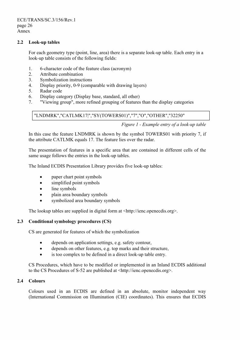
2.2 Look-up tables
For each geometry type (point, line, area) there is a separate look-up table. Each entry in a look-up table consists of the following fields:
1. 6-character code of the feature class (acronym) 2. Attribute combination 3. Symbolization instructions 4. Display priority, 0-9 (comparable with drawing layers) 5. Radar code 6. Display category (Display base, standard, all other) 7. "Viewing group", more refined grouping of features than the display categories
Figure 1 - Example entry of a look-up table
In this case the feature LNDMRK is shown by the symbol TOWERS01 with priority 7, if the attribute CATLMK equals 17. The feature lies over the radar.
The presentation of features in a specific area that are contained in different cells of the same usage follows the entries in the look-up tables.
The Inland ECDIS Presentation Library provides five look-up tables:
• paper chart point symbols • simplified point symbols • line symbols • plain area boundary symbols • symbolized area boundary symbols
The lookup tables are supplied in digital form at <http://ienc.openecdis.org>.
2.3 Conditional symbology procedures (CS)
CS are generated for features of which the symbolization
• depends on application settings, e.g. safety contour, • depends on other features, e.g. top marks and their structure, • is too complex to be defined in a direct look-up table entry.
CS Procedures, which have to be modified or implemented in an Inland ECDIS additional to the CS Procedures of S-52 are published at <http://ienc.openecdis.org>.
2.4 Colours
Colours used in an ECDIS are defined in an absolute, monitor independent way (International Commission on Illumination (CIE) coordinates). This ensures that ECDIS
"LNDMRK","CATLMK17|","SY(TOWERS01)","7","O","OTHER","32250"
ECE/TRANS/SC.3/156/Rev.1 page 27 Annex
charts look similar on monitors of different suppliers. By means of a colour calibration software which must be used by the manufacturer, CIE values are converted into RGB values.
Commercial displays usual in the trade are seen as matching this requirements.
Because of the different lighting conditions on the bridge of a ship, it is necessary to offer presentations with different brightness. For each level a separate colour table exists.
The represented colour scheme shall be chosen on the basis of ergonomically and physiological factors and the representation of indications in different colours shall not result in mixed colours by superimposing.
2.5 Presentation of notice marks
Notice marks which are located at the river bank are presented in the chart displayed by generic symbols (notmrk01, notmrk02 and notmrk03). This does not apply to the notice marks on bridges.
Additionally applications are required to be able to display the detailed symbol, which is similar to the real world indication, and the full set of object information of a user-selected notice mark.
Notice marks that are located at bridges, shall be symbolized according to the orientation of the bridge.
Notice marks which specify distances or a velocity will not be symbolized with the number itself, but only with that symbol which gives the general regulation or information.
3 Maintenance
This section of this edition 2.0 of the standard will be updated by means of the following two documents:
Clarifications Document This contains improvements to the wording of the standard. These are editorial amendments, which do not result in any substantive change to the standard.
Corrections and Extensions Document This contains changes to the standard to correct factual errors and to make necessary amendments or extensions to the standard.
These documents, and the associated maintenance mechanism, do not apply to the Presentation Library for Inland ECDIS. The maintenance procedure under No. 7 of the Product Specification for Inland ENC applies in principle to the maintenance of the Presentation Library too. In this case - unlike the described maintenance procedure - only the European Inland ECDIS Expert Group maintains the Presentation Library for Inland ECDIS.
ECE/TRANS/SC.3/156/Rev.1 page 28 Annex
SECTION 4
Operational and Performance Requirements, Methods of Testing and Required Test Results
1 Introduction
1.1 Scope of this document
This section 4 of the Inland ECDIS Standard specifies the minimum requirements contained in section 1 and describes the test procedures and the required results concerning the hardware, the software, the functions, the operation, the display and the interfaces to other equipment on board of ships.
1.2 Normative references
References to the following normative documents are made in this document in addition to the references in Section 1, Ch. 2.2 of this standard:
EN 60945 (1997) Marine navigational equipment; General requirements - Methods of testing and required test results
ISO 9000 (1987) Quality management and quality assurance standard EU-Directive 1999/5/EC: Radio Equipment and Telecommunications Terminal
Equipment and the Mutual Recognition of their Conformity 2 Operating modes and system configuration
2.1 Operating modes
(a) The Inland ECDIS Standard distinguishes two operating modes: navigation mode and information mode.
(b) Inland ECDIS equipment designed for operating in navigation mode has to fulfil the requirements of this standard and the standards on navigational radar equipment and rate-of-turn indicators to be proven by conformity tests.
(c) For Inland ECDIS equipment designed for information mode only, the requirements of this section 4 are to be understood as a recommendation.
2.2 System configurations
2.2.1 Inland ECDIS equipment, stand-alone-system without connection to radar
In this configuration only operation in information mode is possible (see Appendix B to this section, Fig. 1).
ECE/TRANS/SC.3/156/Rev.1 page 29 Annex
2.2.2 Inland ECDIS equipment, parallel installation and connection to radar
This configuration allows operation in information mode as well as in navigation mode (see Appendix B, Fig. 2).
2.2.3 Inland ECDIS equipment, monitor shared with connected radar equipment
In special cases, it is possible to share one display for the Inland ECDIS equipment and for the radar equipment. The prerequisite for this is a monitor with matching graphic parameters for both video signals, and a video switch, which allows a fast switchover of the video sources, and – if needed - a mechanical rotation of the display to the required orientation (see Appendix B, Fig. 3).
This configuration allows operation in information mode as well as in navigation mode
2.2.4 Radar equipment with integrated Inland ECDIS functionality
This is a radar installation with integrated Inland ECDIS functionality that can be operated in information mode as well as in navigation mode (see Appendix B, Fig. 4).
3 Performance requirements
3.1 Hardware performance
(a) Inland ECDIS equipment shall be designed and manufactured to withstand typical environmental conditions prevailing on board of a vessel without any degradation in quality and reliability. Furthermore, it shall not disturb other communication and navigation equipment.
(b) In the configuration as described in paragraph 2.2.4 all components of inland ECDIS equipment, installed inside the wheelhouse, shall fulfil the requirements of the class b) "protected from weather" equipment as specified in the standard EN 60945 with the exception that the test temperature range is limited to 0° C to + 40° C (whereas the test temperature range in EN 60945 is specified from – 15° C to + 55° C) unless specified differently in this document. For the configurations described in paragraph 2.2.2 and 2.2.3 CE conformity is sufficient.
3.2 Software performance
Operation, visualisation, and functionality of Inland ECDIS equipment are usually realised by software. Taking this into account, the software shall be designed, developed, implemented, and tested according to the generally accepted state of the art. Therefore, the manufacturer shall fulfil the software requirements described in Appendix A to this section.
ECE/TRANS/SC.3/156/Rev.1 page 30 Annex
3.3 Performance of operation controls
(a) The operation of the system shall be simple, appropriate and conform to common human interface standards.
(b) The number of operational controls shall be as low as possible and restricted to the required number.
(c) Wireless remote controls are not admitted.
(d) The ON/OFF switch is to perform and to be arranged in such a way that inadvertent operation is not possible.
(e) The symbols of the operating controls need a minimum character height of 4 mm and have to be readable under all conditions that may exist in a wheelhouse.
(f) The brilliance and the illumination of the operating controls should be adjustable to the required value.
3.4 Display performance
3.4.1 Display dimensions
In navigation mode the minimum chart and radar display area is 270 mm x 270 mm.
3.4.2 Display orientation
(a) A rectangular display may be mounted in landscape or in portrait orientation under the prerequisite that the above-mentioned minimum dimensions are fulfilled.
(b) Because of the limited space available in the typical wheelhouse of an inland vessel and the fact that a vessel usually follows the fairway-axis, the display shall be installed preferably in the portrait orientation.
3.4.3 Display resolution
A display resolution of 5 m in the 1,200 m range is required. This leads to a maximum pixel dimension of 2.5 m x 2.5 m, i.e. about 1,000 pixels at the short edge of the display.
3.4.4 Display colours
The system shall be able to display ergonomically proven colour combinations for day and night.
3.4.5 Display brilliance
The brilliance of the display shall be adjustable to every operational required value. This is especially valid for the lowest value during operation at night.
ECE/TRANS/SC.3/156/Rev.1 page 31 Annex
3.4.6 Picture renewal
(a) The picture renewal rate shall not be shorter than that of the radar picture (≥ 24 pictures per minute).
(b) Between two consecutive renewals no fluctuations of brilliance may occur.
(c) On raster scan displays, the frame repetition rate may not be lower than 60 Hz.
3.4.7 Display technology
Preferably such display systems shall be used that are insensitive to the magnetic fields that may occur in the wheelhouse of an inland vessel.
4 Operational functions
4.1 Operating mode
(a) If the equipment is able to work in both operation modes it shall provide the possibility to switch between navigation mode and information mode.
(b) The operation mode in use shall be displayed.
(c) Suitable measures are required to prevent inadvertent switching off of the navigation mode.
4.2 Equipment pre-sets (store/recall)
(a) After invoking, the Inland ECDIS equipment shall come up with a moderate brilliance pre-set which neither blinds in a dark environment nor makes the picture invisible in a bright environment.
(b) Other parameters may come up with their values at the time before switching off or from stored settings.
4.3 Presentation of SENC information
SENC = System Electronic Navigational Chart
(a) The radar picture shall be clearly distinguishable from the chart independently of the chosen colour table.
(b) Only a monochrome presentation of the actual radar picture is permitted.
(c) The presentation of chart information shall not mask or degrade important parts of the radar picture. This has to be ensured by appropriate entries into the look-up tables (ref. to section 3 of this standard, clause 2.2, field "radar code").
(d) In navigation mode, chart and radar picture presentation shall have the same scale.
ECE/TRANS/SC.3/156/Rev.1 page 32 Annex
(e) The heading line must be always visible.
(f) Additionally, the mariner's own ship’s contour and the safety contours may be inserted.
4.4 Chart orientation, positioning and shifting
(a) In navigation mode, only the chart orientation ”relative motion, head up” and the “centred” or “off centred” presentations, as required for the radar picture, are permitted.
(b) In information mode, at least the chart orientations north and parallel to the waterway axis as well as positioning are recommended. By connection of a positioning sensor, the displayed part of the chart can automatically follow the mariner's own ship's position.
4.5 Position and bearing of the own ship
(a) In navigation mode, the own ships position shall always be visible in the display area, whether “centred” or “off centred” as specified in the CCNR radar requirements.
(b) The heading line, which runs from the display centre to the top and which always shall be visible, shall represent the heading of the mariner's own ship.
4.6 Information density
The information density shall be at least adjustable to the three switch steps: "Minimum", "Standard" and "All Information". The latter displays all other features in addition to the "Standard" display, individually on demand. All corresponding visible features are defined in the "Performance Standard" and the "Presentation Standard” (-> “Presentation Library for Inland ECDIS”) (Sections 1 and 3 of the Inland ECDIS Standard).
4.7 Ranges/range rings
(a) In navigation mode the following fixed ranges and range rings are prescribed according to the radar regulations:
Range Range rings 500 m 100 m 800 m 200 m
1.200 m 200 m 1.600 m 400 m 2.000 m 400 m
(b) Both, smaller as well as larger ranges with a minimum of four and a maximum of six range rings are permitted.
ECE/TRANS/SC.3/156/Rev.1 page 33 Annex
(c) Inland ECDIS equipment in navigation mode shall have fixed range rings with the above-mentioned intervals and at least one variable range marker (VRM).
(d) Switching on/off of fixed and variable range markers shall be independent of each other and their display has to be clearly distinguishable.
(e) The position of the VRM and the corresponding displayed distance shall use the same increments and resolution.
(f) The functions of the VRM and the electronic bearing line (EBL) may additionally be realised by a cursor and by a corresponding numerical display, showing range and bearing of the cursor position.
(g) For information mode the same ranges are recommended.
4.8 Picture brilliance
(a) The brightness of the display shall be adjustable to the operationally necessary value. This applies in particular to operation in darkness.
(b) Chart and radar picture require separate brightness controls.
(c) Because of the strongly different environment brightness of bright day and dark night, another control for the basic brightness of the display shall be available additionally to the colour tables in the menu.
4.9 Picture colours
At least the colour combinations included in the IHO-S-52 Presentation Library, Ch. 4 and 13 (colour tables) for bright day, white-back day, black-back day, dusk and night shall be supported.
4.10 Pick report
(a) In navigation mode, it shall be possible to get all underlying textual and/or graphical information concerning user selections of the features that are displayed in the chart.
(b) This additional textual and/or graphical information shall not hamper the view of the waterway in the navigational chart.
ECE/TRANS/SC.3/156/Rev.1 page 34 Annex
4.11 Measuring features
(a) Measuring features for distances and bearings are required.
(b) Resolution and accuracy shall at least be the same as those of the display, but may not suggest better values than those of the chart data.
4.12 Input and editing of skippers' own chart entries
(a) Inland ECDIS equipment shall allow input, storing, modifying, and deletion of additional chart information by the skipper (skippers' own features).
(b) These own chart entries shall be distinguishable from the SENC data, and may not overlay or degrade the radar picture.
4.13 Loading and updating of SENC’s
(a) All manual activities concerning loading or updating of charts shall be possible only outside the navigation mode.
(b) Automatic updating shall not downgrade the performance of the navigation display.
(c) A rollback function has to be implemented to allow restoring to the last working combination.
4.14 Radar picture presentation and overlay
(a) The radar image representation is mandatory for operation in the navigation mode.9/
(b) The dimensions, resolution and attributes of the radar presentation shall fulfil the relevant radar requirements.
(c) The radar picture must not be degraded by other contents of the picture (see clause 4.3.c)
(d) Provided the functional requirements are fulfilled, overlaying of different information layers is permitted.
(e) The overlay of information regarding the position and orientation of other vessels is only allowed when:
• the information is up-to-date (nearly real-time) and • the age of the information does not exceed 5 seconds
9/ On wide inland waterways Basin Administration may, where appropriate, consider this mandatory requirement as a recommendation.
ECE/TRANS/SC.3/156/Rev.1 page 35 Annex
(f) The overlaid information derived from tracking and tracing devices regarding the position and orientation of other vessels shall be faded out at a user-definable range.
(g) The presentation of the position and the orientation of other vessels by
• a directed triangle or • a true outline (to scale)
are permitted only if the heading of these other vessels is available. In all other cases a generic symbol shall be used (a square is recommended, a circle should be used for inland applications only).
(h) It shall be possible to switch off the chart and any other information layer and to display only the radar picture by one easily accessible control element or menu area.
(i) If the quality and plausibility monitors of the Inland ECDIS equipment detect that the chart cannot be oriented and/or positioned with the accuracy required by this document, an alarm shall be presented on the display and the chart shall be switched off automatically.
4.15 Inland ECDIS functions with immediate access
(a) The following operational functions require direct access:
• RANGE • BRILLIANCE • COLOURS • INFORMATION DENSITY
(b) These functions need either own control elements or own menu areas, which are arranged in the highest menu level and are permanently visible.
4.16 Permanent visible function parameters
The following function parameter shall be always visible:
• actual RANGE • sensor STATUS (radar tuning, position quality, alarms) • selected WATER LEVEL (if available) • selected SAFETY DEPTH (if available) • selected INFORMATION DENSITY
ECE/TRANS/SC.3/156/Rev.1 page 36 Annex
5 Service functions
Service functions have to be protected by password or other suitable measures against unauthorised access and shall not be selectable in navigation mode.
5.1 Static correction of the chart position
(a) The position of the mariner's own ship shall be presented “centred” or “off centred” on the display in accordance with the radar requirements. The chart position shall match the radar image. Assuming an absolute position’s input the permissible static difference between actual radar position and displayed radar centre shall not exceed 1 m.
(b) It shall be possible to correct an offset error (distance between the positions of the position sensor and the radar sensor).
5.2 Static correction of the chart orientation
(a) The difference between the heading line orientation and the ship's axis shall not be greater than ± 1.0 deg.
(b) Chart and radar image shall have the same orientation. The static directional error between heading line and chart orientation shall be less than ± 0.5 deg.
5.3 Configuration of interfaces
(a) It shall be possible to configure interfaces for connected sensors, actors and signals (An actor transforms an electrical quantity into another physical quantity (e.g. optical). An actor is the opposite of a sensor).
(b) Interfaces shall comply with existing interface specifications like the National Marine Electronics Association (NMEA) 01/83 standard and the interface specifications for rate of turn indicators (20 mV/deg/min).
6 Hardware test and required certificates
(a) The test consists of a comparison between the equipment under test (EUT) and the requirements of this document.
(b) Proved equivalent tests, and proved and documented test results will be accepted without renewed tests.
6.1 Compatibility with the environmental requirements
(a) Inland ECDIS equipment, as described in paragraph 2.2.4, shall fulfil the requirements of the Standard EN 60 945 concerning the environmental conditions (humidity, vibration and temperature; the latter reduced according to chapter 3.1 of this document) and concerning electromagnetic compatibility.
ECE/TRANS/SC.3/156/Rev.1 page 37 Annex
(b) The provider or his representative is obliged to submit a relevant conformity declaration of an accredited laboratory.
6.2 Equipment documentation
The technical documentation will be checked to be complete, appropriate, and understandable, and to be sufficient for unproblematic installation, configuration and operation of the equipment.
6.3 Interfaces
(a) All interfaces shall be documented correctly and completely.
(b) Electronic Circuits need to be designed failsafe, mechanically as well as electronically, and may not have degrading repercussions on connected equipment.
6.4 Characteristic of operation controls
All operation controls will be checked regarding the ergonomic and functional mode of operation and shall fulfil the requirements of this document.
6.5 Characteristic of the display
The display shall fulfil all requirements of this document concerning dimension, displayable colours, resolution, and variation of brilliance.
7 Test of the chart presentation, operation and functionality
7.1 Preparation of the equipment under test (EUT)
The EUT will be installed, assembled and connected according to the installation manual. After switching on the test SENC will be loaded.
7.2 Test of the operation modes
All operating modes as described in the operating manual will be successively invoked and tested. The requirements of chapter 4 shall be fulfilled.
7.3 Test of the displayed features
Whether all features included in the test SENC are visible and correctly displayed will be tested. For this test, the information density will be switched to “all features”. The system shall be capable to at least display all features according to the “Presentation Standard for Inland ECDIS” (Section 3 of the Inland ECDIS Standard). Additionally other user-selectable symbol sets are allowed.
ECE/TRANS/SC.3/156/Rev.1 page 38 Annex
7.4 Test of the scale dependent information density (SCAMIN)
(a) Whether the SCAMIN functionality (the minimum scale at which the feature may be used for ECDIS presentation) is installed correctly will be tested.
(b) For this test, the range will be used at which the feature shall be visible according to its SCAMIN enumeration (ref. to the IHO-S-57 Attribute Catalogue and the IHO-S-52 Users Manual to the Presentation Library, ch. 8.4).
7.5 Test of brilliance variation
The Inland ECDIS equipment will be operated in a dark room and the brilliance will be brought to its lowest level. The brilliance of the features shall not exceed a value of 15 cd/m2, and the background a value of 0,5 cd/m2.
7.6 Test of the colours
All user selectable S-52 colour tables will be sequentially tested to conform to this document.
7.7 Test of the measurement functions
(a) All numeric displayed values of the electronic bearing line (EBL) and the variable range marker (VRM) shall exactly match with the analogue positions of the EBL and the VRM (or correspond with the cursor co-ordinates).
(b) The resolution and increments of the numerical display shall be identical with the analogue values of EBL and VRM.
7.8 Test of the chart update function
(a) Before and after every test step the version numbers of the loaded SENCs and updates will be recalled as described in the operation manual and showed on the display.
• Step 1: Loading of the test SENC, • Step 2: Update of the test SENC, • Step 3: Test of the roll-back function, • Step 4: Loading of a new SENC.
After an update it should be possible to recall and display all concerning features.
7.9 Test of displayed features in more than one cell of the same usage for the same area
It will be tested whether all features included in the test SENC and in the additional overlay test SENC are visible and correctly displayed. For this test the information density will be switched to “all features”. It will be tested whether it is possible to select one or more specific cells for presentation if there are several cells from different producers for the same area with the same usage.
ECE/TRANS/SC.3/156/Rev.1 page 39 Annex
8 Test of radar picture presentation and operation
8.1 Preparations
(a) For the test purposes, the manufacturer or provider has to provide a serial interface at the system to be approved (Equipment under test - EUT) which delivers the same actual values (as NMEA 01/83 strings) of position and heading that are used to position and orient the chart.
(b) During the test, a reference system will be used of which position and heading values are compared with those of the EUT.
(c) The EUT will be connected to any type approved radar equipment (to the choice of the provider).
(d) The radar picture will be adjusted in range and bearing with reference to the heading line.
8.2 Test of the radar picture without underlaid chart
(a) If the Inland ECDIS equipment displays the radar picture but the radar operation control remains at the radar equipment (App. B, figures 2 and 3), the radar picture of the inland ECDIS equipment will be considered as the "daughter display" of an item of radar equipment. In that case, the radar picture has to fulfil the display and picture-relevant requirements of the requirements for radar and rate-of-turn indicators.
(b) If the EUT is a radar installation with integrated Inland ECDIS functionality (Appendix B, figure 4), all requirements of the standards for radar equipment and rate-of-turn indicators have to be fulfilled.
8.3 Test of the radar picture, overlaid information from other vessels and the underlying chart
The Inland ECDIS equipment will be installed in a reference environment. This can be real (on a ship) or simulated. Position and orientation information of other vessels (conform the Inland AIS standard) will be applied with several information ages.
8.3.1 Test of the radar overlay
(a) The radar image shall not be degraded by the chart picture (ref. to ch. 4.3.c).
(b) The overlay of information regarding the position and orientation of other vessels is only displayed when:
• the information is up-to-date (nearly real-time) and • the age of the information does not exceed 5 seconds
ECE/TRANS/SC.3/156/Rev.1 page 40 Annex
(c) The overlay of information derived from tracking and tracing devices regarding the position and orientation of other vessels is faded out at a user-definable range.
(d) The position and the orientation of other vessels by
• a directed triangle or
• a true outline (to scale)
is displayed only when the heading of these other vessels is available. For all other vessels a generic symbol is used (a square is recommended, a circle should be used for inland applications only).
(e) It is possible to switch off the chart and any other information layer and to display only the radar picture by one easily accessible control element or menu area.
(f) The chart picture shall be renewed not later than the radar picture.
8.3.2 Test of the chart positioning and orientation
(a) The static offset of the chart position shall be less than ± 5 m in all ranges up to 2,000 m.
(b) The static azimuth orientation offset error between radar and chart image shall be less than ± 0,5 deg.
(c) The correction of these parameters shall be demonstrated in the service mode.
(d) The dynamic deviation of the chart orientation at rates of turn less than ± 60 deg./min shall be less than ± 3 deg.
(e) These tests will be performed visually or by evaluation of measured data.
8.3.3 Test of scale conformity
The chart’s information will be compared with well-known reference points contained in the radar picture in order to test whether the chart scale sufficiently conforms to the radar scale.
ECE/TRANS/SC.3/156/Rev.1 page 41 Annex
9 Test of alarms and indications
(a) The alarms generated from Inland ECDIS equipment itself as well as the passed alarms delivered by the connected sensors to the ECDIS will be tested.
(b) The test procedure comprises the following situations:
• any error in the Inland ECDIS equipment (built-in test equipment - BITE), • missing positioning signal, • missing radar signal, • missing rate of turn signal, • missing heading signal, • radar map matching not possible.
10 Test of fall back arrangements
(a) This test shall demonstrate the reaction of the Inland ECDIS equipment to a failure of any internal or external component and the possible and required actions by the operator.
(b) In addition, the operating manual will be checked to determine whether the measures required by the operator are described adequately and appropriately.
11 Maintenance
This section of this edition 2.0 of the standard will be updated by means of the following two documents:
Clarifications Document This contains improvements to the wording of the standard. These are editorial amendments, which do not result in any substantive change to the standard.
Corrections and Extensions Document This contains changes to the standard to correct factual errors and to make necessary amendments or extensions to the standard.

ECE/TRANS/SC.3/156/Rev.1 page 42 Annex
APPENDIX A: MEASURES TO ENSURE SOFTWARE QUALITY
1 General requirements
Software used in navigation mode is assumed to be a safety-relevant part of a navigation system. Providers of navigation systems have to make sure that all software components used in navigation mode allow secure navigation in every situation.
1.1 Software design requirements
Software components have to be clearly designed by means of established software design methods. The design specification must indicate how safety requirements are addressed in the software design.
A software style guide has to be provided that specifies code writing style, documentation style, modularization, conflict analyses and testing of software components. For every software component, documents describing specification and design are required.
1.2 Implementation requirements
Implementation of software modules has to be done by qualified developers, fully understanding the design and safety requirements.
If more than one developer is working on the navigation system software, a version control system has to be used that guarantees conflict-free development.
The implementation has to be according to the design specification and has to reflect the software style guide. Moreover, well known implementation problems (depending on the language used) have to be addressed in the implementation. This includes but is not restricted to:
• null pointer handling, • uninitialised variables, • range checking, • array size verification, • memory allocation and de-allocation, • exception handling.
If parallel processing is used (e.g. multiple threads, tasks or processes) problems of conflict-free processing have to be addressed in the implementation. This includes but is not restricted to:
• race conditions, • re-entrance problems, • priority inversion, • deadlocks.

ECE/TRANS/SC.3/156/Rev.1 page 43 Annex
1.3 Test requirements
In accordance with the design specification, software modules have to be tested. The test results have to be compared with the design guidelines and documented in test reports.
Tests have to incorporate module as well as system tests. Providers of a navigation system have to use extensive simulator-based tests to ensure stability of their system. The simulator must allow the simulation of a complete navigation environment including all required external sensors.
1.4 Third party components requirements
Third party components (Original equipment manufacturer (OEM) products) include software not developed by the navigation system provider. This includes but is not restricted to
• static or dynamic linked libraries, • computer aided design and engineering tools producing source or object code, • operating systems.
Third party software components have to be chosen according to the general safety requirements. The navigation system provider has to prove that third party components meet the high standards necessary for safe navigation either by providing acceptable quality certificates or by extensive and provable testing of the components.
1.5 Requirements for additional services in navigation mode
Navigation systems may support additional services in navigation mode if they are useful. These services must not interfere with navigation mode.
The navigation system provider is responsible for additional test equipment, necessary to verify interface specification, protocol specification and compliance tests with the Inland ECDIS standard.
1.6 Language
Additional national versions of a type-approved Inland ECDIS shall reapply for type approval to be checked for the translation of the user interface.
1.7 Documentation requirements for users
The documentation (manuals) has to contain comprehensive information on installation, operation and service of the navigation system. The presentation of user-relevant information shall be made clear, understandable and without unnecessary technical terms. The user manual shall be available in the official CCNR languages. The technical documentation may be made available in English only.
ECE/TRANS/SC.3/156/Rev.1 page 44 Annex
2 Methods of testing and required results
2.1 Navigation mode operation test
2.1.1 Performance requirements
Navigation systems must make reliable estimations of position and heading. Moreover, the estimation of position and heading has to be checked by the system for conformity with the required accuracy.
Position and heading information has to be calculated and displayed for the same reference position. This should normally be the centre of the radar antenna. A new position estimate must at least be available with every revolution of the radar antenna.
2.1.1.1 Position
The navigation system has to estimate and display the position of the ship. The following minimal requirements have to be fulfilled under normal operation conditions:
(a) The average position estimation shall not deviate more than 5 meters from the true position and shall cover all systematic errors.
(b) The standard deviation σ has to be less than 5 meters and shall be based on random errors only.
(c) The system shall be capable to detect deviations of more than 3σ within 30 seconds.
These results have to be verified by a realistic test of at least 60 min.
2.1.1.2 Heading
The navigation system has to estimate and display the heading of the ship.
The following minimal requirements have to be fulfilled:
(a) The average heading angle estimation shall not deviate more than 1 degree from the radar heading direction and shall cover all systematic errors. The offset between ship heading direction and radar heading shall be less than 1 degree.
(b) The standard deviation σ has to be less than 2 degrees and shall be only based on random errors.
These results have to be verified by a realistic test of at least 60 min.
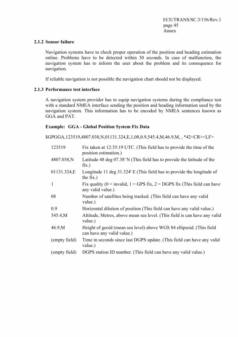
ECE/TRANS/SC.3/156/Rev.1 page 45 Annex
2.1.2 Sensor failure
Navigation systems have to check proper operation of the position and heading estimation online. Problems have to be detected within 30 seconds. In case of malfunction, the navigation system has to inform the user about the problem and its consequence for navigation.
If reliable navigation is not possible the navigation chart should not be displayed.
2.1.3 Performance test interface
A navigation system provider has to equip navigation systems during the compliance test with a standard NMEA interface sending the position and heading information used by the navigation system. This information has to be encoded by NMEA sentences known as GGA and PAT.
Example: GGA - Global Position System Fix Data
$GPGGA,123519,4807.038,N,01131.324,E,1,08,0.9,545.4,M,46.9,M, , *42<CR><LF>
123519 Fix taken at 12:35:19 UTC. (This field has to provide the time of the position estimation.)
4807.038,N Latitude 48 deg 07.38' N (This field has to provide the latitude of the fix.)
01131.324,E Longitude 11 deg 31.324' E (This field has to provide the longitude of the fix.)
1 Fix quality (0 = invalid, 1 = GPS fix, 2 = DGPS fix (This field can have any valid value.)
08 Number of satellites being tracked. (This field can have any valid value.)
0.9 Horizontal dilution of position (This field can have any valid value.) 545.4,M Altitude, Metres, above mean sea level. (This field is can have any valid
value.) 46.9,M Height of geoid (mean sea level) above WGS 84 ellipsoid. (This field
can have any valid value.) (empty field) Time in seconds since last DGPS update. (This field can have any valid
value.) (empty field) DGPS station ID number. (This field can have any valid value.)
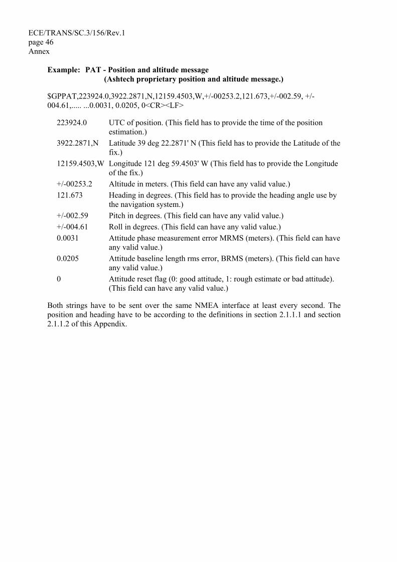
ECE/TRANS/SC.3/156/Rev.1 page 46 Annex
Example: PAT - Position and altitude message (Ashtech proprietary position and altitude message.)
$GPPAT,223924.0,3922.2871,N,12159.4503,W,+/-00253.2,121.673,+/-002.59, +/-004.61,..... ...0.0031, 0.0205, 0<CR><LF>
223924.0 UTC of position. (This field has to provide the time of the position estimation.)
3922.2871,N Latitude 39 deg 22.2871' N (This field has to provide the Latitude of the fix.)
12159.4503,W Longitude 121 deg 59.4503' W (This field has to provide the Longitude of the fix.)
+/-00253.2 Altitude in meters. (This field can have any valid value.) 121.673 Heading in degrees. (This field has to provide the heading angle use by
the navigation system.) +/-002.59 Pitch in degrees. (This field can have any valid value.) +/-004.61 Roll in degrees. (This field can have any valid value.) 0.0031 Attitude phase measurement error MRMS (meters). (This field can have
any valid value.) 0.0205 Attitude baseline length rms error, BRMS (meters). (This field can have
any valid value.) 0 Attitude reset flag (0: good attitude, 1: rough estimate or bad attitude).
(This field can have any valid value.)
Both strings have to be sent over the same NMEA interface at least every second. The position and heading have to be according to the definitions in section 2.1.1.1 and section 2.1.1.2 of this Appendix.
ECE/TRANS/SC.3/156/Rev.1 page 47 Annex
2.2 General software tests
2.2.1 Equipment documentation
The following documents have to be provided for admittance and have to be shipped with every navigation system:
• Users manual, • Installation manual, • Service manual.
The following documents and files have to be provided during the admittance procedure and are not required for end users:
• design specification, • software style guide, • certificates of third party software components or test and simulation protocols.
The documents and files provided must allow a complete verification of compliance with the Inland ECDIS standard.
2.2.2 Endurance test
The navigation system must pass an endurance test of 48 hours of uninterrupted operation under normal operation conditions. The system has to provide standard interfaces for performance and resource monitoring during operation. Monitoring the system must show no indication of system instability, memory leaking or any kind of performance loss over time. Navigation systems supporting additional services while running in navigation mode provide the necessary test equipment including all documents mentioned in chapter 1.7 of this Appendix.
3 Changes to certified systems
3.1 General requirements
Navigation systems installed on board must be functionally equivalent to a system certified by authorities. For every system the navigation system provider must ship a statement of compliance with the Inland ECDIS standard and its functional equivalence to the certified system.
The competent authority is entitled to check Inland ECDIS compliance of installed systems at any time.
3.2 Hardware and software changes
The navigation system provider can change software or hardware as long as Inland ECDIS compliance is maintained. Changes have to be fully documented and submitted to the competent authority together with an explanation of how the navigation system is affected
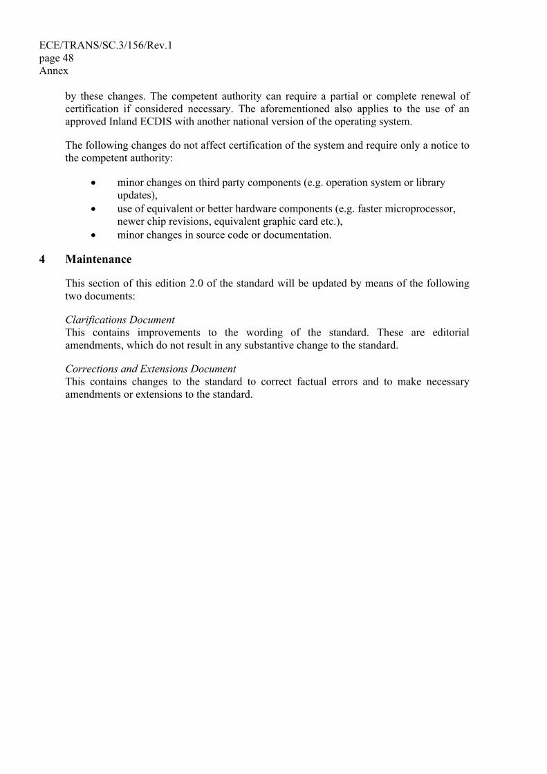
ECE/TRANS/SC.3/156/Rev.1 page 48 Annex
by these changes. The competent authority can require a partial or complete renewal of certification if considered necessary. The aforementioned also applies to the use of an approved Inland ECDIS with another national version of the operating system.
The following changes do not affect certification of the system and require only a notice to the competent authority:
• minor changes on third party components (e.g. operation system or library updates),
• use of equivalent or better hardware components (e.g. faster microprocessor, newer chip revisions, equivalent graphic card etc.),
• minor changes in source code or documentation.
4 Maintenance
This section of this edition 2.0 of the standard will be updated by means of the following two documents:
Clarifications Document This contains improvements to the wording of the standard. These are editorial amendments, which do not result in any substantive change to the standard.
Corrections and Extensions Document This contains changes to the standard to correct factual errors and to make necessary amendments or extensions to the standard.
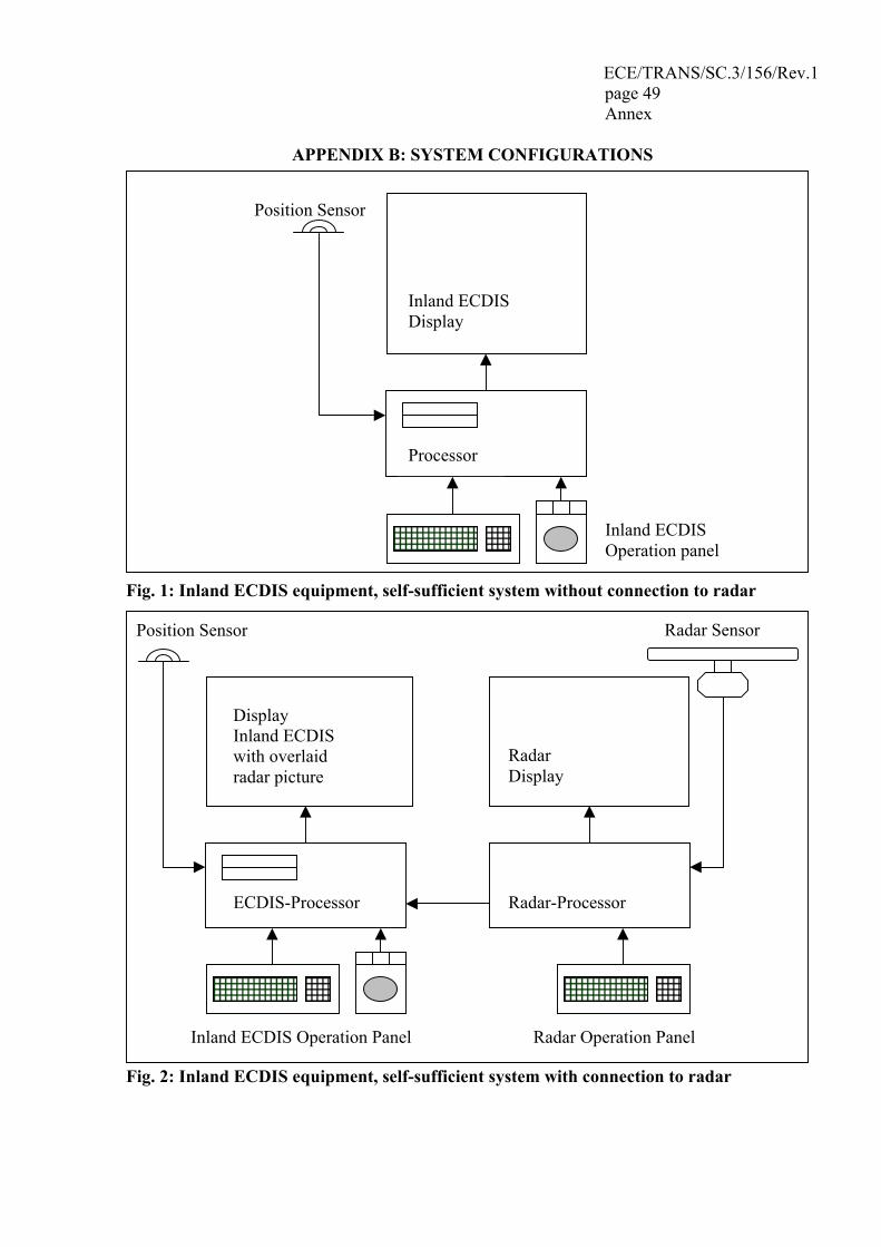
ECE/TRANS/SC.3/156/Rev.1 page 49 Annex
APPENDIX B: SYSTEM CONFIGURATIONS
Fig. 1: Inland ECDIS equipment, self-sufficient system without connection to radar
Fig. 2: Inland ECDIS equipment, self-sufficient system with connection to radar
Position Sensor
Display Inland ECDIS with overlaid radar picture
ECDIS-Processor
Inland ECDIS Operation Panel
Radar Sensor
Radar Display
Radar-Processor
Radar Operation Panel
Position Sensor
Processor
Inland ECDIS Operation panel
Inland ECDIS Display
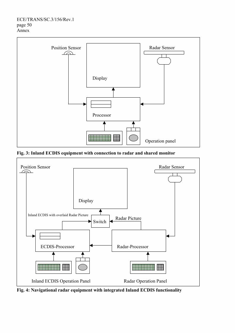
ECE/TRANS/SC.3/156/Rev.1 page 50 Annex
Fig. 3: Inland ECDIS equipment with connection to radar and shared monitor
Fig. 4: Navigational radar equipment with integrated Inland ECDIS functionality
Position Sensor
Processor
Operation panel
Display
Radar Sensor
Position Sensor
Display
ECDIS-Processor
Inland ECDIS Operation Panel
Radar Sensor
Radar-Processor
Radar Operation Panel
Inland ECDIS with overlaid Radar PictureRadar Picture
Switch
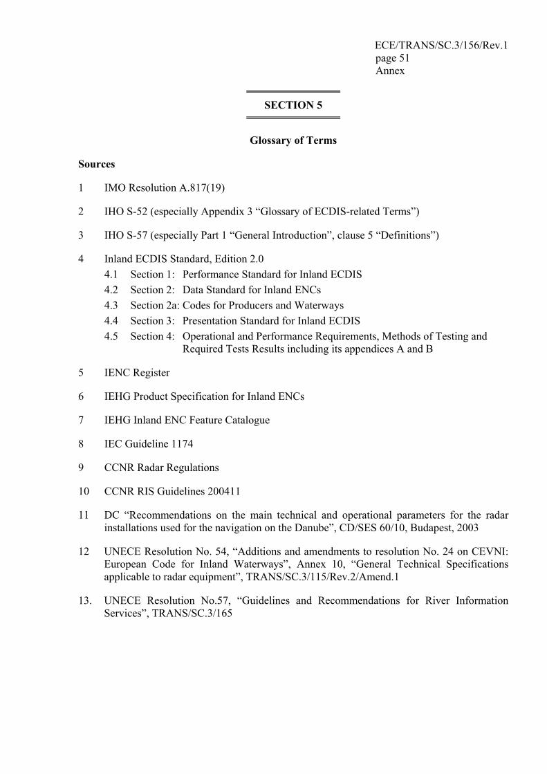
ECE/TRANS/SC.3/156/Rev.1 page 51 Annex
SECTION 5
Glossary of Terms
Sources
1 IMO Resolution A.817(19)
2 IHO S-52 (especially Appendix 3 “Glossary of ECDIS-related Terms”)
3 IHO S-57 (especially Part 1 “General Introduction”, clause 5 “Definitions”)
4 Inland ECDIS Standard, Edition 2.0 4.1 Section 1: Performance Standard for Inland ECDIS 4.2 Section 2: Data Standard for Inland ENCs 4.3 Section 2a: Codes for Producers and Waterways 4.4 Section 3: Presentation Standard for Inland ECDIS 4.5 Section 4: Operational and Performance Requirements, Methods of Testing and
Required Tests Results including its appendices A and B
5 IENC Register
6 IEHG Product Specification for Inland ENCs
7 IEHG Inland ENC Feature Catalogue
8 IEC Guideline 1174
9 CCNR Radar Regulations
10 CCNR RIS Guidelines 200411
11 DC “Recommendations on the main technical and operational parameters for the radar installations used for the navigation on the Danube”, CD/SES 60/10, Budapest, 2003
12 UNECE Resolution No. 54, “Additions and amendments to resolution No. 24 on CEVNI: European Code for Inland Waterways”, Annex 10, “General Technical Specifications applicable to radar equipment”, TRANS/SC.3/115/Rev.2/Amend.1
13. UNECE Resolution No.57, “Guidelines and Recommendations for River Information Services”, TRANS/SC.3/165
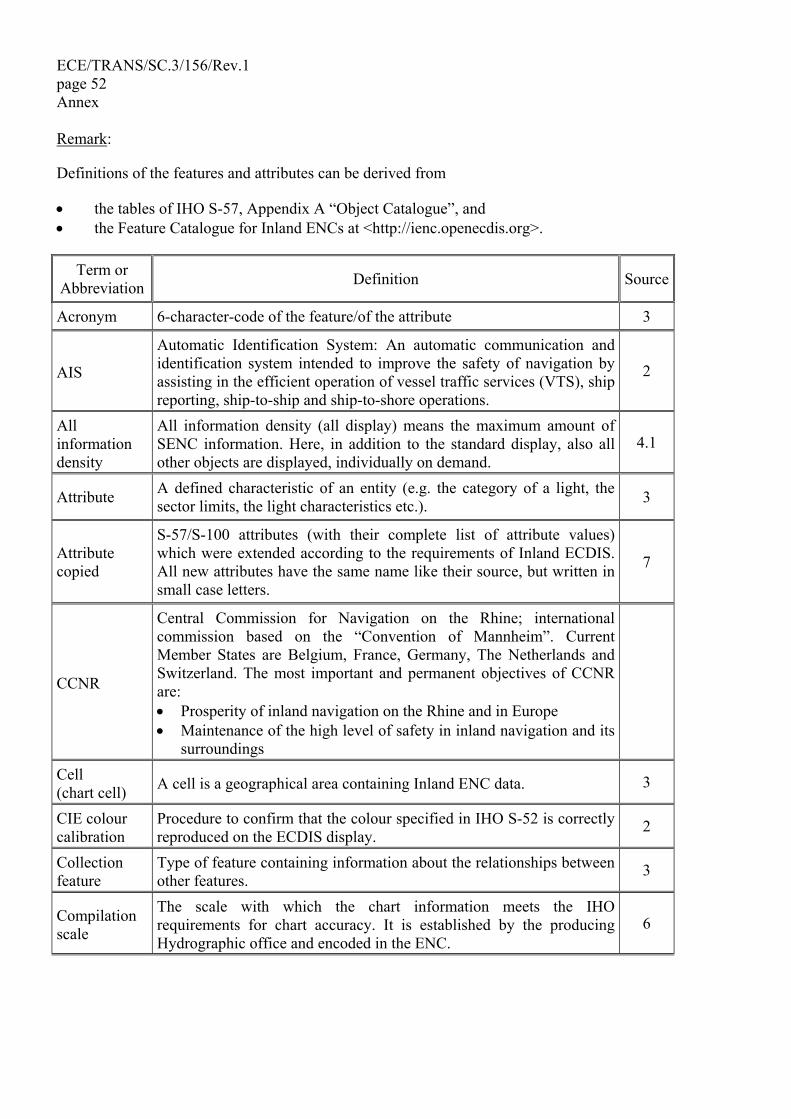
ECE/TRANS/SC.3/156/Rev.1 page 52 Annex
Remark:
Definitions of the features and attributes can be derived from
• the tables of IHO S-57, Appendix A “Object Catalogue”, and • the Feature Catalogue for Inland ENCs at <http://ienc.openecdis.org>.
Term or Abbreviation Definition Source
Acronym 6-character-code of the feature/of the attribute 3
AIS
Automatic Identification System: An automatic communication and identification system intended to improve the safety of navigation by assisting in the efficient operation of vessel traffic services (VTS), ship reporting, ship-to-ship and ship-to-shore operations.
2
All information density
All information density (all display) means the maximum amount of SENC information. Here, in addition to the standard display, also all other objects are displayed, individually on demand.
4.1
Attribute A defined characteristic of an entity (e.g. the category of a light, the sector limits, the light characteristics etc.). 3
Attribute copied
S-57/S-100 attributes (with their complete list of attribute values) which were extended according to the requirements of Inland ECDIS. All new attributes have the same name like their source, but written in small case letters.
7
CCNR
Central Commission for Navigation on the Rhine; international commission based on the “Convention of Mannheim”. Current Member States are Belgium, France, Germany, The Netherlands and Switzerland. The most important and permanent objectives of CCNR are: • Prosperity of inland navigation on the Rhine and in Europe • Maintenance of the high level of safety in inland navigation and its
surroundings
Cell (chart cell) A cell is a geographical area containing Inland ENC data. 3
CIE colour calibration
Procedure to confirm that the colour specified in IHO S-52 is correctly reproduced on the ECDIS display.
2
Collection feature
Type of feature containing information about the relationships between other features.
3
Compilation scale
The scale with which the chart information meets the IHO requirements for chart accuracy. It is established by the producing Hydrographic office and encoded in the ENC.
6
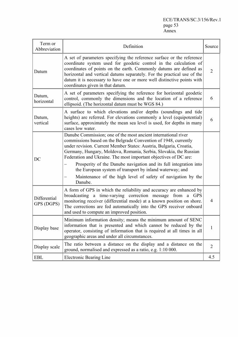
ECE/TRANS/SC.3/156/Rev.1 page 53 Annex
Term or Abbreviation Definition Source
Datum
A set of parameters specifying the reference surface or the reference coordinate system used for geodetic control in the calculation of coordinates of points on the earth. Commonly datums are defined as horizontal and vertical datums separately. For the practical use of the datum it is necessary to have one or more well distinctive points with coordinates given in that datum.
2
Datum, horizontal
A set of parameters specifying the reference for horizontal geodetic control, commonly the dimensions and the location of a reference ellipsoid. (The horizontal datum must be WGS 84.)
6
Datum, vertical
A surface to which elevations and/or depths (soundings and tide heights) are referred. For elevations commonly a level (equipotential) surface, approximately the mean sea level is used, for depths in many cases low water.
6
DC
Danube Commission; one of the most ancient international river commissions based on the Belgrade Convention of 1948, currently under revision. Current Member States: Austria, Bulgaria, Croatia, Germany, Hungary, Moldova, Romania, Serbia, Slovakia, the Russian Federation and Ukraine. The most important objectives of DC are: − Prosperity of the Danube navigation and its full integration into
the European system of transport by inland waterway; and − Maintenance of the high level of safety of navigation by the
Danube.
Differential GPS (DGPS)
A form of GPS in which the reliability and accuracy are enhanced by broadcasting a time-varying correction message from a GPS monitoring receiver (differential mode) at a known position on shore. The corrections are fed automatically into the GPS receiver onboard and used to compute an improved position.
4
Display base
Minimum information density; means the minimum amount of SENC information that is presented and which cannot be reduced by the operator, consisting of information that is required at all times in all geographic areas and under all circumstances.
1
Display scale The ratio between a distance on the display and a distance on the ground, normalised and expressed as a ratio, e.g. 1:10 000.
2
EBL Electronic Bearing Line 4.5
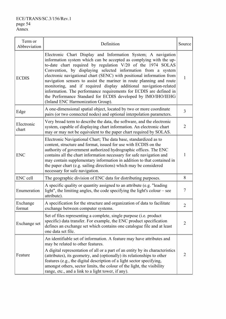
ECE/TRANS/SC.3/156/Rev.1 page 54 Annex
Term or Abbreviation Definition Source
ECDIS
Electronic Chart Display and Information System; A navigation information system which can be accepted as complying with the up-to-date chart required by regulation V/20 of the 1974 SOLAS Convention, by displaying selected information from a system electronic navigational chart (SENC) with positional information from navigation sensors to assist the mariner in route planning and route monitoring, and if required display additional navigation-related information. The performance requirements for ECDIS are defined in the Performance Standard for ECDIS developed by IMO/IHO/IEHG (Inland ENC Harmonization Group).
1
Edge A one-dimensional spatial object, located by two or more coordinate pairs (or two connected nodes) and optional interpolation parameters.
3
Electronic chart
Very broad term to describe the data, the software, and the electronic system, capable of displaying chart information. An electronic chart may or may not be equivalent to the paper chart required by SOLAS.
2
ENC
Electronic Navigational Chart; The data base, standardized as to content, structure and format, issued for use with ECDIS on the authority of government authorized hydrographic offices. The ENC contains all the chart information necessary for safe navigation and may contain supplementary information in addition to that contained in the paper chart (e.g. sailing directions) which may be considered necessary for safe navigation.
1
ENC cell The geographic division of ENC data for distributing purposes. 8
Enumeration A specific quality or quantity assigned to an attribute (e.g. "leading light", the limiting angles, the code specifying the light's colour – see attribute).
7
Exchange format
A specification for the structure and organization of data to facilitate exchange between computer systems.
2
Exchange set
Set of files representing a complete, single purpose (i.e. product specific) data transfer. For example, the ENC product specification defines an exchange set which contains one catalogue file and at least one data set file.
2
Feature
An identifiable set of information. A feature may have attributes and may be related to other features. A digital representation of all or a part of an entity by its characteristics (attributes), its geometry, and (optionally) its relationships to other features (e.g., the digital description of a light sector specifying, amongst others, sector limits, the colour of the light, the visibility range, etc., and a link to a light tower, if any).
2
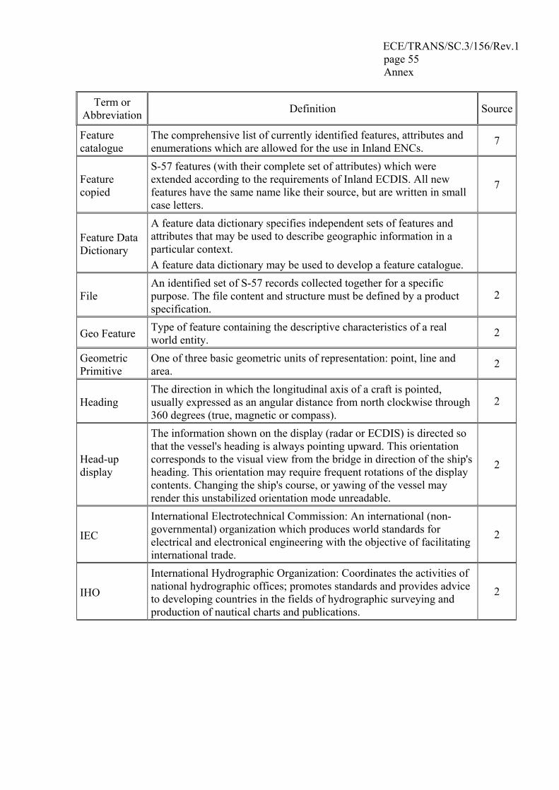
ECE/TRANS/SC.3/156/Rev.1 page 55 Annex
Term or Abbreviation Definition Source
Feature catalogue
The comprehensive list of currently identified features, attributes and enumerations which are allowed for the use in Inland ENCs.
7
Feature copied
S-57 features (with their complete set of attributes) which were extended according to the requirements of Inland ECDIS. All new features have the same name like their source, but are written in small case letters.
7
Feature Data Dictionary
A feature data dictionary specifies independent sets of features and attributes that may be used to describe geographic information in a particular context. A feature data dictionary may be used to develop a feature catalogue.
File An identified set of S-57 records collected together for a specific purpose. The file content and structure must be defined by a product specification.
2
Geo Feature Type of feature containing the descriptive characteristics of a real world entity.
2
Geometric Primitive
One of three basic geometric units of representation: point, line and area.
2
Heading The direction in which the longitudinal axis of a craft is pointed, usually expressed as an angular distance from north clockwise through 360 degrees (true, magnetic or compass).
2
Head-up display
The information shown on the display (radar or ECDIS) is directed so that the vessel's heading is always pointing upward. This orientation corresponds to the visual view from the bridge in direction of the ship's heading. This orientation may require frequent rotations of the display contents. Changing the ship's course, or yawing of the vessel may render this unstabilized orientation mode unreadable.
2
IEC
International Electrotechnical Commission: An international (non-governmental) organization which produces world standards for electrical and electronical engineering with the objective of facilitating international trade.
2
IHO
International Hydrographic Organization: Coordinates the activities of national hydrographic offices; promotes standards and provides advice to developing countries in the fields of hydrographic surveying and production of nautical charts and publications.
2
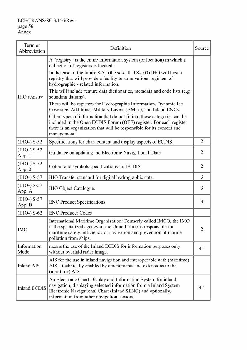
ECE/TRANS/SC.3/156/Rev.1 page 56 Annex
Term or Abbreviation Definition Source
IHO registry
A “registry” is the entire information system (or location) in which a collection of registers is located. In the case of the future S-57 (the so-called S-100) IHO will host a registry that will provide a facility to store various registers of hydrographic - related information. This will include feature data dictionaries, metadata and code lists (e.g. sounding datums). There will be registers for Hydrographic Information, Dynamic Ice Coverage, Additional Military Layers (AMLs), and Inland ENCs. Other types of information that do not fit into these categories can be included in the Open ECDIS Forum (OEF) register. For each register there is an organization that will be responsible for its content and management.
(IHO-) S-52 Specifications for chart content and display aspects of ECDIS. 2
(IHO-) S-52 App. 1 Guidance on updating the Electronic Navigational Chart 2
(IHO-) S-52 App. 2 Colour and symbols specifications for ECDIS. 2
(IHO-) S-57 IHO Transfer standard for digital hydrographic data. 3
(IHO-) S-57 App. A IHO Object Catalogue. 3
(IHO-) S-57 App. B ENC Product Specifications. 3
(IHO-) S-62 ENC Producer Codes
IMO
International Maritime Organization: Formerly called IMCO, the IMO is the specialized agency of the United Nations responsible for maritime safety, efficiency of navigation and prevention of marine pollution from ships.
2
Information Mode
means the use of the Inland ECDIS for information purposes only without overlaid radar image.
4.1
Inland AIS AIS for the use in inland navigation and interoperable with (maritime) AIS – technically enabled by amendments and extensions to the (maritime) AIS
Inland ECDIS
An Electronic Chart Display and Information System for inland navigation, displaying selected information from a Inland System Electronic Navigational Chart (Inland SENC) and optionally, information from other navigation sensors.
4.1
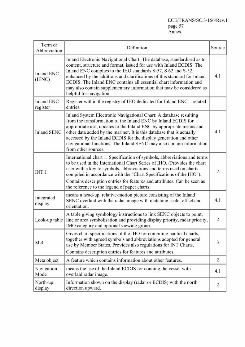
ECE/TRANS/SC.3/156/Rev.1 page 57 Annex
Term or Abbreviation Definition Source
Inland ENC (IENC)
Inland Electronic Navigational Chart: The database, standardised as to content, structure and format, issued for use with Inland ECDIS. The Inland ENC complies to the IHO standards S-57, S 62 and S-52, enhanced by the additions and clarifications of this standard for Inland ECDIS. The Inland ENC contains all essential chart information and may also contain supplementary information that may be considered as helpful for navigation.
4.1
Inland ENC register
Register within the registry of IHO dedicated for Inland ENC – related entries.
Inland SENC
Inland System Electronic Navigational Chart: A database resulting from the transformation of the Inland ENC by Inland ECDIS for appropriate use, updates to the Inland ENC by appropriate means and other data added by the mariner. It is this database that is actually accessed by the Inland ECDIS for the display generation and other navigational functions. The Inland SENC may also contain information from other sources.
4.1
INT 1
International chart 1: Specification of symbols, abbreviations and terms to be used in the International Chart Series of IHO. (Provides the chart user with a key to symbols, abbreviations and terms used on charts compiled in accordance with the "Chart Specifications of the IHO"). Contains description entries for features and attributes. Can be seen as the reference to the legend of paper charts.
2
Integrated display
means a head-up, relative-motion picture consisting of the Inland SENC overlaid with the radar-image with matching scale, offset and orientation.
4.1
Look-up table A table giving symbology instructions to link SENC objects to point, line or area symbolisation and providing display priority, radar priority, IMO category and optional viewing group.
2
M-4
Gives chart specifications of the IHO for compiling nautical charts, together with agreed symbols and abbreviations adopted for general use by Member States. Provides also regulations for INT Charts. Contains description entries for features and attributes.
3
Meta object A feature which contains information about other features. 2
Navigation Mode
means the use of the Inland ECDIS for conning the vessel with overlaid radar image.
4.1
North-up display
Information shown on the display (radar or ECDIS) with the north direction upward.
2
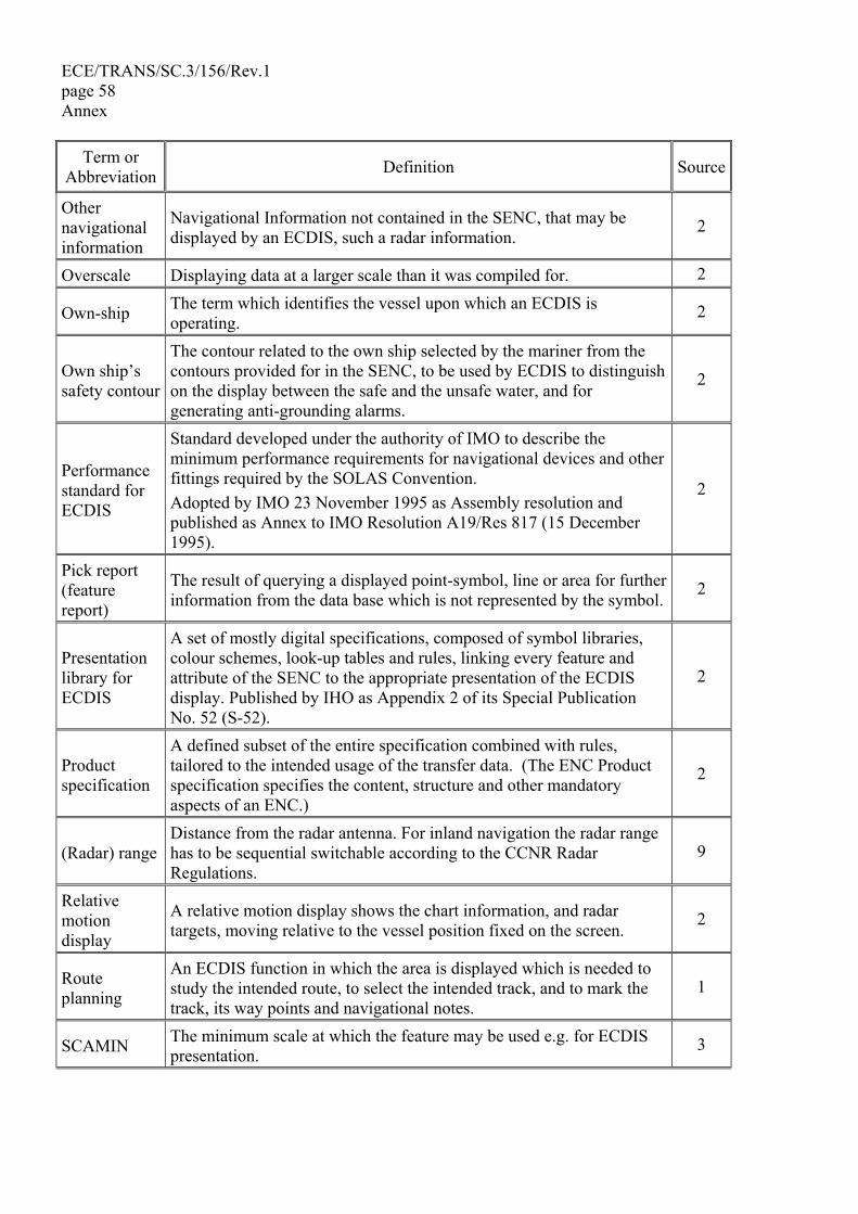
ECE/TRANS/SC.3/156/Rev.1 page 58 Annex
Term or Abbreviation Definition Source
Other navigational information
Navigational Information not contained in the SENC, that may be displayed by an ECDIS, such a radar information.
2
Overscale Displaying data at a larger scale than it was compiled for. 2
Own-ship The term which identifies the vessel upon which an ECDIS is operating.
2
Own ship’s safety contour
The contour related to the own ship selected by the mariner from the contours provided for in the SENC, to be used by ECDIS to distinguish on the display between the safe and the unsafe water, and for generating anti-grounding alarms.
2
Performance standard for ECDIS
Standard developed under the authority of IMO to describe the minimum performance requirements for navigational devices and other fittings required by the SOLAS Convention. Adopted by IMO 23 November 1995 as Assembly resolution and published as Annex to IMO Resolution A19/Res 817 (15 December 1995).
2
Pick report (feature report)
The result of querying a displayed point-symbol, line or area for further information from the data base which is not represented by the symbol.
2
Presentation library for ECDIS
A set of mostly digital specifications, composed of symbol libraries, colour schemes, look-up tables and rules, linking every feature and attribute of the SENC to the appropriate presentation of the ECDIS display. Published by IHO as Appendix 2 of its Special Publication No. 52 (S-52).
2
Product specification
A defined subset of the entire specification combined with rules, tailored to the intended usage of the transfer data. (The ENC Product specification specifies the content, structure and other mandatory aspects of an ENC.)
2
(Radar) range Distance from the radar antenna. For inland navigation the radar range has to be sequential switchable according to the CCNR Radar Regulations.
9
Relative motion display
A relative motion display shows the chart information, and radar targets, moving relative to the vessel position fixed on the screen.
2
Route planning
An ECDIS function in which the area is displayed which is needed to study the intended route, to select the intended track, and to mark the track, its way points and navigational notes.
1
SCAMIN The minimum scale at which the feature may be used e.g. for ECDIS presentation. 3
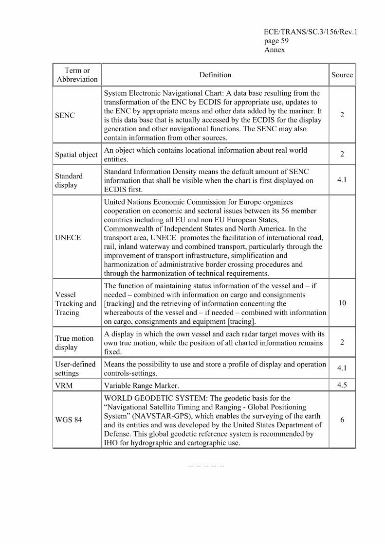
ECE/TRANS/SC.3/156/Rev.1 page 59 Annex
Term or Abbreviation Definition Source
SENC
System Electronic Navigational Chart: A data base resulting from the transformation of the ENC by ECDIS for appropriate use, updates to the ENC by appropriate means and other data added by the mariner. It is this data base that is actually accessed by the ECDIS for the display generation and other navigational functions. The SENC may also contain information from other sources.
2
Spatial object An object which contains locational information about real world entities.
2
Standard display
Standard Information Density means the default amount of SENC information that shall be visible when the chart is first displayed on ECDIS first.
4.1
UNECE
United Nations Economic Commission for Europe organizes cooperation on economic and sectoral issues between its 56 member countries including all EU and non EU European States, Commonwealth of Independent States and North America. In the transport area, UNECE promotes the facilitation of international road, rail, inland waterway and combined transport, particularly through the improvement of transport infrastructure, simplification and harmonization of administrative border crossing procedures and through the harmonization of technical requirements.
Vessel Tracking and Tracing
The function of maintaining status information of the vessel and – if needed – combined with information on cargo and consignments [tracking] and the retrieving of information concerning the whereabouts of the vessel and – if needed – combined with information on cargo, consignments and equipment [tracing].
10
True motion display
A display in which the own vessel and each radar target moves with its own true motion, while the position of all charted information remains fixed.
2
User-defined settings
Means the possibility to use and store a profile of display and operation controls-settings.
4.1
VRM Variable Range Marker. 4.5
WGS 84
WORLD GEODETIC SYSTEM: The geodetic basis for the “Navigational Satellite Timing and Ranging - Global Positioning System” (NAVSTAR-GPS), which enables the surveying of the earth and its entities and was developed by the United States Department of Defense. This global geodetic reference system is recommended by IHO for hydrographic and cartographic use.
6
___________