Embed Size (px)
Citation preview

Moltaí i dtaobh Oibreacha Forbartha Láithreáin le haghaidh Limistéir Tithíochta
AN ROINN COMHSHAOIL AGUS RIALTAIS ÁITIÚIL
DEPARTMENT OF THE ENVIRONMENTAND LOCAL GOVERNMENT
9 780707 661636
ISBN 0-7076-6163-3

i
AN ROINN COMHSHAOIL AGUS RIALTAIS ÁITIÚIL
DEPARTMENT OF THE ENVIRONMENTAND LOCAL GOVERNMENT
Recommendations forSite Development Worksfor Housing Areas
October, 1998
Printed onRecycled Paper
Dublin
Published by the Stationery Office, Dublin
To be purchased from:
The Government Publications Sale Office
Sun Alliance House
Molesworth Street
Dublin 2.
Price £10.00

ii
© Government of Ireland 1998
BAILE ÁTHA CLIATH
ARNA FHOILSIÚ AG OIFIG AN TSOLÁTHAIR
Le ceannach díreach ón
OIFIG DHÍOLTA FOILSEACHÁN RIALTAIS
TEACH SUN ALLIANCE, SRÁID THEACH LAIGHEAN, BAILE ÁTHA CLIATH 2
nó tríd an bpost ó
FOILSEACHÁIN RIALTAIS, AN RANNÓG POST-TRÁCHTA,
4-5 BÓTHAR FHEARCHAIR, BAILE ÁTHA CLIATH 2
(Teil: 01-6613111, fo-líne 4040/4045; Fax: 01-4752760)
nó trí aon díoltóir leabhar.
DUBLIN
PUBLISHED BY THE STATIONERY OFFICE
To be purchased directly from the
GOVERNMENT PUBLICATIONS SALE OFFICE
SUN ALLIANCE HOUSE, MOLESWORTH STREET, DUBLIN 2
or by mail order from
GOVERNMENT PUBLICATIONS, POSTAL TRADE SECTION,
4-5 HARCOURT ROAD, DUBLIN 2
(Tel: 01-6613111, extension 4040/4045; Fax: 01-4752760)
or through any bookseller.
ISBN 0-7076-6163-3
P.62370. 1000. 10/98. Brunswick Press Ltd. Gr. 30-01

Contents
Clause Page
FOREWORD vii
SECTION 1: GENERAL
1.1 Definitions 11.2 Scope 21.3 Technical Specifications 21.4 Materials 21.5 Consultation with Local Authority 31.6 Information Required 41.7 Other Services 51.8 Access 51.9 Completion 51.10 Legal 5
SECTION 2: ROADS AND FOOTWAYS
2.1 Layout Design 62.2 Roadway Width 62.3 Junctions 62.4 Junction Sightlines 62.5 Junction Radii 72.6 Cul-de-sac Ends 72.7 Road Gradients 72.8 Road Crossfall 92.9 Horizontal Alignment 92.10 Driveways 92.11 Screen Walls 92.12 Services 92.13 Clearance 92.14 Specification 92.15 Roadway Construction 92.16 Subgrade Strength 102.17 Depth of Sub-base and Capping Layer 112.18 Capping Layer Material 122.19 Sub-base Material 122.20 Roadbase Material 132.21 Concrete Roadways 142.22 Block Paving Roadways 182.23 Flexible Roadways 192.24 Surface Dressing 192.25 Footways 192.26 Kerbs 202.27 Cement 202.28 Concrete Aggregates 20
iii

iv
Clause Page
SECTION 3: SEWERS AND DRAINS
3.1 Compliance 213.2 Separate Systems 213.3 Pipe Types 213.4 Pipe Sizes and Gradients, Surface Water 213.5 Pipe Sizes and Gradients, Foul Water 233.6 Bedding and Cover, Rigid Pipes 233.7 Bedding and Cover, Flexible Pipes 253.8 Trench Width 263.9 Trench Compaction 263.10 Accessibility 273.11 Access to Sewers 273.12 Drain to Sewer Connections 273.13 Joints 273.14 Manhole Construction 273.15 Manhole Dimensions 283.16 Channels and Benching 293.17 Manhole Covers and Frames 303.18 Manhole Steps and Ladders 303.19 Gullies 313.20 Testing of Sewers and Drains 323.21 Manhole Infiltration 333.22 Cleaning of Sewers and Drains 33
SECTION 4: WATER SUPPLY
4.1 Supply 344.2 Watermain Pipes 344.3 Service Pipes 344.4 Watermain Pipe Size and Layout 344.5 Watermain Class 344.6 Pipe Cover 344.7 Pipe Laying 344.8 Pipe Jointing 354.9 Marker Tape 354.10 Pipe Anchorage 354.11 Sluice Valves 354.12 Hydrants 354.13 Air Valves 354.14 Stopcocks 354.15 Valve Chambers 354.16 Surface Boxes 374.17 Indicator Plates and Marker Posts 374.18 Testing and Sterilisation 38

v
Clause Page
SECTION 5: PUBLIC LIGHTING
5.1 Introduction 405.2 Standards 405.3 Minimum Illuminance Levels 415.4 Lighting Columns and Brackets 425.5 Lanterns 435.6 Fitting Out of Columns 445.7 Control 455.8 Auxiliary Public Lighting Micro Pillar 455.9 Fitting Out of Auxiliary Public Lighting Micro Pillar 455.10 Cable and Ducting 475.11 Earthing 475.12 Column Installation 49
REFERENCES 50
FIGURES
SECTION 2:
2.1 Clear Sight-triangle 62.2 Residential Turning Bays 82.3 Terminology for Roadway Construction 102.4 Transverse Contraction Joint 162.5 Transverse Expansion Joint 162.6 Longitudinal Joint 172.7 Formed Contraction Joint 17
SECTION 3:
3.1 Bedding and Surround for Rigid Drainage Pipes 243.2 Bedding and Surround for Flexible Drainage Pipes 26
SECTION 4:
4.1 Hydrant, Airvalve and Sluice Valve Chambers 364.2 Stopcock Chamber 374.3 Concrete Marker Post 38
SECTION 5:
5.1 Lighting Column Bracket 435.2 Internal Electrical Arrangement, Public Lighting Column 445.3 Internal Electrical Arrangement, Auxiliary Micro Pillar 465.4 High Voltage Warning Sign 47

vi

vii
FOREWORD
This document, which is an update of a similarly entitled An Foras Forbartha publication, (originally issued in 1974 and
subsequently amended in 1984) is intended for the guidance of local authorities, public authorities, private developers and
consultants, in the construction of site development works for housing areas.
The document sets out recommended standards and technical specifications for the various services, which should generally be
acceptable to local authorities, in their administrative areas.
This publication does not contain all of the possible solutions to site development design problems and designers should be
encouraged to propose imaginative alternatives, subject to approval as defined in the document.
It should be noted also, that some local authorities provide their own documented requirements in relation to site development
works.
This document does not deal with issues of estate layout. Nevertheless, it is recognised that layouts which seek to ensure very
low traffic speeds and greater priority for pedestrians and cyclists within housing areas should be encouraged. In particular
circumstances, this consideration might well justify the adoption of standards other than those contained in this document.

viii
1.1 Definitions For the purposes of this document, the following definitions apply:
1. Local Authority: The Local Authority which will assume responsibility for the
development works on their completion.
2. Developer: The person, company or public body that undertakes the development
works and from whom the Local Authority would take the development in charge.
3. Approval: "Approval" and "Approved" mean approval in writing by the Local Authority,
of proposals submitted by the developer. This meaning does not extend to a planning
application for "approval", unless it is specifically stated as such.
4. Road: A way for vehicles and other types of traffic.
5. Roadway: That portion of a road which is provided primarily for the use of vehicles.
6. Footpath: A road over which there is a public right of way for pedestrians only, not
being a footway.
7. Footway: That portion of any road associated with a roadway, which is provided
primarily for use by pedestrians.
8. Drain: Any underground pipework or conduit used for the conveyance of foul water
or surface water, which is not intended to be taken over and maintained by the Local
Authority.
9. Sewer: Any underground pipework or conduit used for the conveyance of foul water
or surface water, which is intended to be taken over and maintained by the Local
Authority.
10. Foul Water: Waste water, or trade effluent, or water containing excreted matter,
whether human or animal.
11. Surface Water: The run-off of rainwater from roofs and paved ground surfaces.
12. Watermain: A pipe for the general distribution of water in a water supply system, not
being a service pipe.
13. Service Pipe: A pipe for the conveyance of water from a watermain to an individual
premises.
1
Section 1: General

1.2 Scope This document sets out recommended standards and technical specifications for the design
and construction of roads and services associated with site development works for housing
areas. It does not deal with workmanship criteria. The roads and services within the scope
of this document are:
1. All roads within housing areas, with the exception of those intended:
(a) as the principal means of access to more than 200 houses.
(b) for use as bus routes.
(c) to provide a through route for vehicular traffic.
2. Sewers and drains comprising pipes up to 300mm diameter
3. Watermains up to 225mm diameter and water service pipes.
4. Public Lighting within the housing area.
1.3 Technical Specifications Within this document, technical specifications are either provided directly, or indirectly by
reference to:
1. An Irish Standard Specification, identified by IS followed by a number and the year of
publication.
2. A British Standard Specification, identified by BS followed by a number and the year of
publication.
3. A harmonized European Standard Specification, identified by IS EN followed by a number
and the year of publication.
4. Other published specifications, identified by their titles.
References to Irish, British and harmonized European Standard Specifications and any other
published specifications, are to the latest edition current at the time of publication of this
document. However, if this edition of the technical specification is subsequently revised or
updated by the issuing body, the new version should be deemed to apply, unless approval is
obtained to the contrary.
1.4 Materials All works should be carried out with proper materials. Proper materials means materials
which are fit for the use for which they are intended and for the conditions in which they are
to be used, and includes materials which:
2
1. Bear a CE Marking in accordance with the provisions of the Construction Products
Directive; or
2. Comply with an appropriate harmonized standard, European technical approval or
national technical specification as defined in article 4(2) of the Construction Products
Directive; or
3. Comply with an appropriate Irish Standard or Irish Agrément Board Certificate or with
an alternative national technical specification of any State which is a contracting party to
the Agreement on the European Economic Area, which provides in use an equivalent
level of safety and suitability.
1.5 Consultation with Local Authority requirements vary on the nature and degree of consultation that is necessary,
Local Authority in relation to proposed housing developments in their individual administrative areas.
Prior to finalising the design of a proposal, the Developer is advised to ascertain the particular
consultation process that obtains in the specific area, as well as the name(s) of the appropriate
officer(s) for consultation purposes, on matters of Planning, Roads, Drainage, Watermains and
Public Lighting. The Developer is furthermore advised to consult, at the earliest possible
opportunity, with the appropriate officer(s) on matters such as:
1. Planning: Site suitability, layout design, housing density, open spaces, landscaping, etc.
2. Roads: Road reservations, road widening lines, culs-de-sac, junction sightlines and radii,
gradients, alignments, roadway type, proposed construction traffic; inspection, testing
and approval requirements, etc.
3. Drainage: The type of drainage system to be used, areas external to the development
area whose drainage is required to be included (together with estimated discharge data),
outfall points or connections to existing sewers, types of manhole and gully covers;
inspection, testing and approval requirements, etc.
Where the drainage layout is such as to require one or more connections to a public
sewer, the Developer should ascertain whether or not the connections would be carried
out by the Local Authority. Where these connections would be carried out by the
Developer, the Local Authority requirements should be determined.
4. Watermains: Type and layout of watermain, connection points, types of surface boxes,
locations of indicator plates and marker posts; inspection, testing and approval
requirements, etc.
3

5. Public Lighting: Installation by ESB or private contractor, types of lighting column,
lantern, lamp, ducting, cables, controls; inspection, testing and approval requirements,
etc.
1.6 Information Required The following information should be submitted by the Developer to the Local Authority.
(This information may be included in the Developer's application for Planning Permission, or
Approval, or may take the form of such documentation, together with supplementary data,
all subject to approval).
1. A layout plan of the proposed development, showing the extent of the development site,
site contours levels at 0.5m intervals, the location of boundaries and structures within
the site and the location and levels of existing utilities, including those within the site as
well as those external to the site, that would be affected by the development.
2. A plan showing the arrangement of the houses, with proposed ground floor levels, the
layout of roads, footpaths, footways, sewers and drains, including sewer and drain sizes
and positions of manholes and gullies.
3. A plan showing the layout of proposed watermains, including pipe sizes and positions of
hydrants and valves.
4. Longitudinal sections and cross-sections of roads, indicating the proposed road
construction, levels and gradients.
5. Longitudinal sections of proposed sewers and drains, showing levels, gradients, sizes,
types and classes of pipe, types of joint and types of bedding, haunch and surround.
6. Longitudinal sections of proposed watermains, showing sizes, types and classes of pipe
and positions of valves and hydrants.
7. A layout plan with sections of the proposed public lighting system, showing the location
of lighting columns, auxiliary micro pillars and ducting and specifying the types of
equipment to be provided. Details of the internal electrical arrangement for lighting
columns and auxiliary micro pillars, as well as details of the overall earthing arrangements
should also be included.
8. Drainage design calculations, demonstrating the capacity of the proposed pipe networks
to discharge the design flows and run-off from the development.
9. Proposals for the treatment of existing surface and underground water-courses,
boundaries and structures, within the development.
4

10. Proposals for the preservation of existing trees and other features.
Layout plans should be to a scale of not less than 1:500. Sections and elevations should be
to a scale of not less than 1:100. All levels shown should be related to Ordnance Datum.
1.7 Other Services With regard to services other than those being provided directly by the Developer e.g.
electricity, telecommunications, gas, piped television etc., the Developer should comply with
the requirements of statutory undertakers, or public utility companies responsible for such
services. In relation to services on offer from private companies, the Developer should
ascertain the Local Authority requirements in each specific instance.
All necessary ducting for services under roads should be installed, at the approved locations
and depths, prior to completion of the road surfacing.
1.8 Access Access to the site should be made available to Local Authority staff, for such monitoring or
inspection of work as may be required, during construction.
1.9 Completion On completion of the project, the Developer should submit to the Local Authority, such as-
constructed records as the Local Authority may require. This may entail the provision of
some, or all of the drawings detailed in 1.6 above, but might also require the provision of
closed circuit television sewer condition surveys, by approved contractors, with results
presented on diskette, tape, compact disc, or other approved device.
1.10 Legal Compliance with these recommendations does not confer immunity on the Developer from
any legal requirements and does not remove the obligation on the Developer to comply with
the requirements of the Planning Acts, relevant sections of the Building Regulations, the Safety
Health and Welfare at Work Act 1989, etc.
5
6
Design
2.1 Layout Design Layouts should be designed so as to deter through traffic. Road alignments should be such
as to limit vehicle speeds and facilitate pedestrian movement. However, narrower roadway
widths should only be considered where realistic measures have been incorporated to
eliminate on-street parking. Adequate access for wheelchairs and prams should be provided.
2.2 Roadway Width The roadway width should be 6m except for culs-de-sac less than 60m long, where a width
of 5.5m should be acceptable. A reduced roadway width may be approved for short spur
culs-de-sac.
The amount of off-roadway parking to be provided per house, is subject to approval.
2.3 Junctions An uncontrolled intersection is an intersection that does not rely on the positive controls of
signs, or signals, for the allocation of priority amongst approach roads. Junctions should
normally be designed as uncontrolled intersections, to the requirements of the National
Roads Authority publication "Geometric Design Guidelines (Intersections at Grade) RT181".
All junctions internal to the development should be T-junctions. The stagger of these
junctions and the layout of junctions with other roads, are subject to approval.
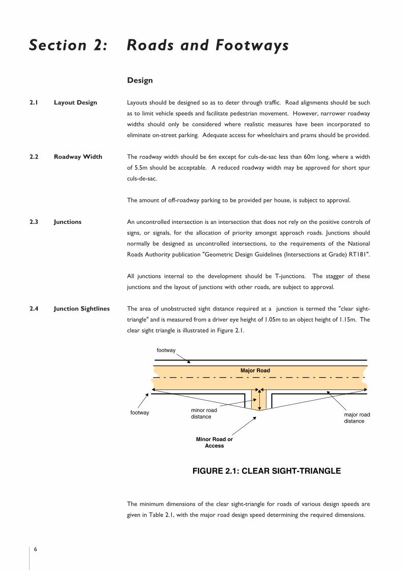
2.4 Junction Sightlines The area of unobstructed sight distance required at a junction is termed the "clear sight-
triangle" and is measured from a driver eye height of 1.05m to an object height of 1.15m. The
clear sight triangle is illustrated in Figure 2.1.
The minimum dimensions of the clear sight-triangle for roads of various design speeds are
given in Table 2.1, with the major road design speed determining the required dimensions.
Section 2: Roads and Footways
major roaddistance
footway
Major Road
minor roaddistance
Minor Road orAccess
footway
FIGURE 2.1: CLEAR SIGHT-TRIANGLE
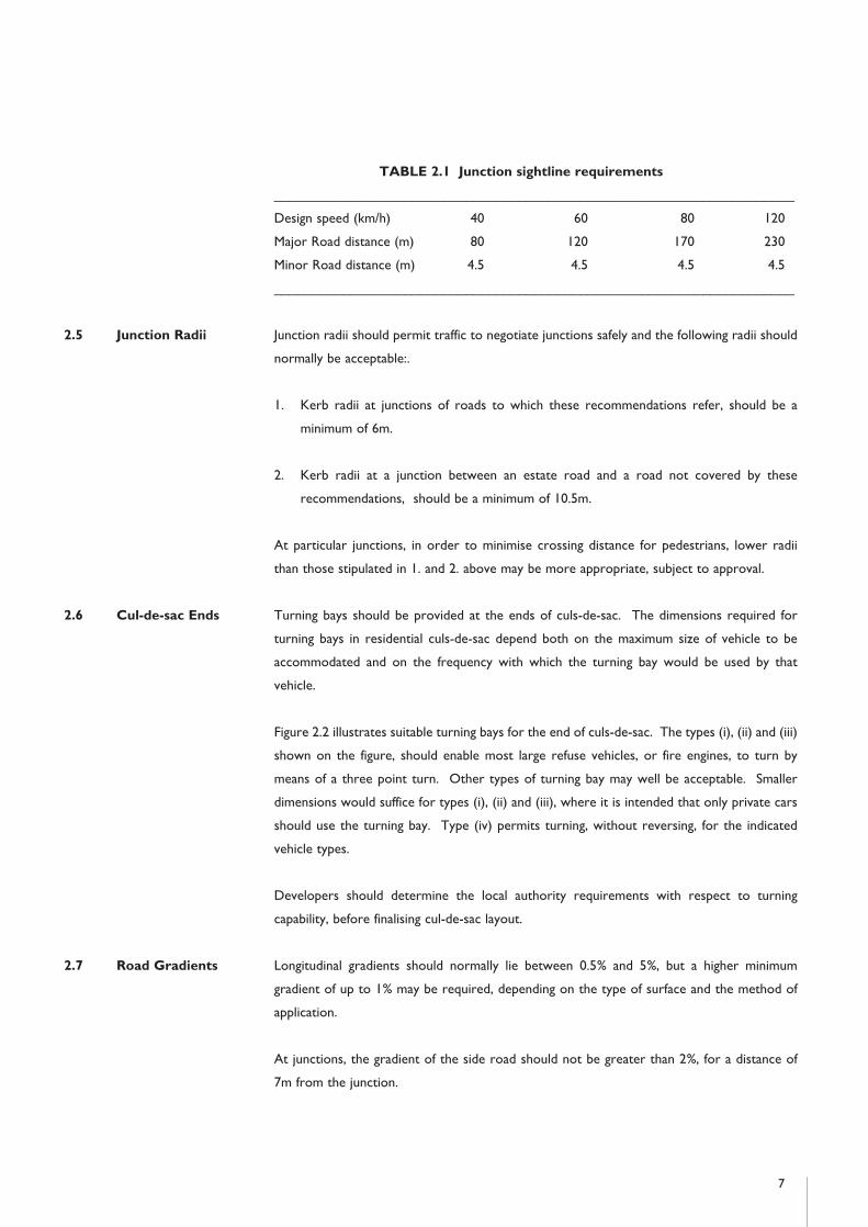
TABLE 2.1 Junction sightline requirements
____________________________________________________________________
Design speed (km/h) 40 60 80 120
Major Road distance (m) 80 120 170 230
Minor Road distance (m) 4.5 4.5 4.5 4.5
____________________________________________________________________
2.5 Junction Radii Junction radii should permit traffic to negotiate junctions safely and the following radii should
normally be acceptable:.
1. Kerb radii at junctions of roads to which these recommendations refer, should be a
minimum of 6m.
2. Kerb radii at a junction between an estate road and a road not covered by these
recommendations, should be a minimum of 10.5m.
At particular junctions, in order to minimise crossing distance for pedestrians, lower radii
than those stipulated in 1. and 2. above may be more appropriate, subject to approval.
2.6 Cul-de-sac Ends Turning bays should be provided at the ends of culs-de-sac. The dimensions required for
turning bays in residential culs-de-sac depend both on the maximum size of vehicle to be
accommodated and on the frequency with which the turning bay would be used by that
vehicle.
Figure 2.2 illustrates suitable turning bays for the end of culs-de-sac. The types (i), (ii) and (iii)
shown on the figure, should enable most large refuse vehicles, or fire engines, to turn by
means of a three point turn. Other types of turning bay may well be acceptable. Smaller
dimensions would suffice for types (i), (ii) and (iii), where it is intended that only private cars
should use the turning bay. Type (iv) permits turning, without reversing, for the indicated
vehicle types.
Developers should determine the local authority requirements with respect to turning
capability, before finalising cul-de-sac layout.
2.7 Road Gradients Longitudinal gradients should normally lie between 0.5% and 5%, but a higher minimum
gradient of up to 1% may be required, depending on the type of surface and the method of
application.
At junctions, the gradient of the side road should not be greater than 2%, for a distance of
7m from the junction.
7

8
19m1m 1m
11.5m1m 5.5mor
6.0m
5.5mor
6.0m
6m
6m
1m R(see table)
6m
6m
5.5m
1m
1m
6m
10m
120°120°
10m
6m
6m
6m
5.5m
1m
1m
13m
5.5m
1m
1m
1m
5.5mor
6.0m
5.5mor
6.0m
Type (ii)Type (i)
Type (iv)
Type (iii)
1m clearance for vehicle overhang shown dashed
NOT TO SCALE
Value of R which permits turningwithout reversing
Vehicle Type R metres
Private Car
Fire Engine
Refuse Vehicle
Furniture Removal
6
9
10
11
FIGURE 2.2: RESIDENTIAL TURNING BAYS

2.8 Road Crossfall A crossfall of 2.5% should be provided for a normal machine laid surface. This may be
decreased to 2% for a high quality surface finish, or may be increased to 3% for hand laid
surfaces.
2.9 Horizontal Roads should normally be designed and located to intersect at angles of between 70 and 110
Alignment degrees and preferably at 90 degrees. Where one road crosses or meets another at an angle
outside this range, suitable curves should be introduced in the alignment of the minor road,
subject to approval, in order to improve the angle of intersection.
2.10 Driveways Driveways should have a minimum width of 3m and a maximum gradient of 10%. A kerb
upstand of 25mm should be provided at entrances.
2.11 Screen Walls Screen walls should be constructed in accordance with the requirements of IS 325.
2.12 Services Services should be laid underground, adjacent to the roadway. The laying of services in other
locations is subject to approval.
The public area, including the footway (if any) beside the roadway, should be of sufficient
width to accommodate the services required. Services should only be laid under the roadway
where there is a requirement to cross the roadway. In such cases, services should be laid at
right angles to the roadway.
2.13 Clearance The normal minimum lateral clearance of fixed objects from the roadway edge should be one
metre. This applies to items such as public lighting columns, posts, trees and piers at
entrances to developments. Particular circumstances may require that this clearance be
reduced. In no circumstance should this clearance be less than 450mm.
Construction
2.14 Specification Road works should comply with the requirements of "Specification for Road Works"
published by the Department of the Environment.
2.15 Roadway The roadway construction comprises the pavement layers and the pavement foundation. The
Construction pavement may be constructed using flexible materials, block paving, or in situ concrete. The
pavement foundation comprises the sub-base and capping layer, laid over the natural subgrade
soil.
The various construction options and the terminology for roadway construction are
illustrated in Figure 2.3. In situ concrete, or flexible roadway, are the general forms of
construction. Other forms, such as concrete paving blocks, or clay or calcium silicate pavers
may also be appropriate, subject to approval.
9

2.16 Subgrade Strength Subgrade strength should be established by means of the California Bearing Ratio (CBR) Test,
in accordance with BS 1377: Part 4: Section 7. Samples should be taken at the rate of one
per 100m of road and where significant variations in soil type are anticipated. Extra samples
may be required by the Local Authority where the difference in strength between two
adjacent samples indicates a significant variation in soil type. In preparing the test specimen,
the method of compaction should be the Static Compaction Method 2, as specified in
paragraph 7.2.3.3 of BS 1377: Part 4.
The moisture content and density conditions used in the test should reproduce, as closely as
possible, the conditions likely to apply under the road after construction. To estimate the
appropriate density condition, a preliminary test may be carried out using the vibrating
hammer method of compaction given in BS 1377: Part 4: Section 3, but with the soil at the
expected average moisture content after construction. The CBR specimen should then be
compacted to a density corresponding with 95% of the value obtained in the preliminary test.
In establishing subgrade strength, due account should be taken of the likely impact of the
construction phase on the characteristics of the subgrade material. This may be critical,
particularly on a site with a relatively high water table or poor drainage parameters. In such
10
FLEXIBLEROADWAY
BituminousSurfacing
Roadbase
BLOCK PAVINGROADWAY
Block Surfacing
Laying Course
Sub-Base
Capping Layer (see Note 2)
Subgrade
Roadbase(see Note 1)
IN SITU CONCRETEROADWAY
Concrete Pavement
Foundation
FIGURE 2.3: TERMINOLOGY FOR ROADWAY CONSTRUCTION
NOTE:1. In lightly trafficked situations, a Roadbase would not be required under a Block Paving
Roadway.2. No capping layer is required with a subgrade CBR greater than 15%.
cases, the in-service long term strength of the subgrade may be considerably less than that of
the same soil in an undisturbed condition.
For subgrades with a CBR of less than 2%, a geotextile separator should be used and specialist
advice should be sought regarding minimum thicknesses.
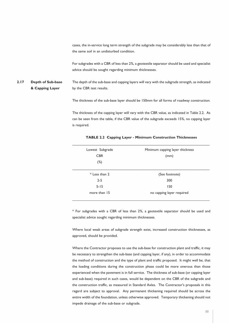
2.17 Depth of Sub-base The depth of the sub-base and capping layers will vary with the subgrade strength, as indicated
& Capping Layer by the CBR test results.
The thickness of the sub-base layer should be 150mm for all forms of roadway construction.
The thickness of the capping layer will vary with the CBR value, as indicated in Table 2.2. As
can be seen from the table, if the CBR value of the subgrade exceeds 15%, no capping layer
is required.
TABLE 2.2 Capping Layer - Minimum Construction Thicknesses
____________________________________________________________________
Lowest Subgrade Minimum capping layer thickness
CBR (mm)
(%)
____________________________________________________________________
* Less than 2 (See footnote)
2-5 300
5-15 150
more than 15 no capping layer required
____________________________________________________________________
* For subgrades with a CBR of less than 2%, a geotextile separator should be used and
specialist advice sought regarding minimum thicknesses.
Where local weak areas of subgrade strength exist, increased construction thicknesses, as
approved, should be provided.
Where the Contractor proposes to use the sub-base for construction plant and traffic, it may
be necessary to strengthen the sub-base (and capping layer, if any), in order to accommodate
the method of construction and the type of plant and traffic proposed. It might well be, that
the loading conditions during the construction phase could be more onerous than those
experienced when the pavement is in full service. The thickness of sub-base (or capping layer
and sub-base) required in such cases, would be dependent on the CBR of the subgrade and
the construction traffic, as measured in Standard Axles. The Contractor's proposals in this
regard are subject to approval. Any permanent thickening required should be across the
entire width of the foundation, unless otherwise approved. Temporary thickening should not
impede drainage of the sub-base or subgrade.
11

12
Damage caused by construction traffic should be remedied, as approved, before construction
of the pavement layers.
2.18 Capping Layer Capping layer material should comprise either crushed rock, natural gravel, crushed gravel,
Material or crushed concrete. The material should have a maximum size of 100mm and the maximum
allowable passing the 75 micron sieve should be 10%. The material should be well graded
throughout all sizes.
Selected demolition materials which meet the above requirements may also be used, subject
to approval.
2.19 Sub-base Material Sub-base material should comprise Type B granular material, in accordance with Clause 804
of the Specification for Roadworks. The material should lie within the grading limits set out
in Table 2.3.
TABLE 2.3 Sub-base Material - Range of Grading
____________________________________________________________________
Sieve size Percentage by
IS 24 mass passing
____________________________________________________________________
75 mm 100
37.5mm 85-100
10 mm 40-70
5 mm 25-45
600 µm 8-22
75 µm 0-10
____________________________________________________________________
Particle size distribution should be determined by the washing and sieving method of BS 812:
Part 103. All material used should be frost resistant
Material passing the 425µm sieve, when tested in accordance with BS 1377, should be non-
plastic.
The material should have a ten percent fines value of 100kN, or more, when tested in
accordance with BS 812.
The sub-base should be laid and compacted to the requirements of Clause 802 of the
Specification for Roadworks, without drying out, or segregation.
Other materials may be used, subject to approval.
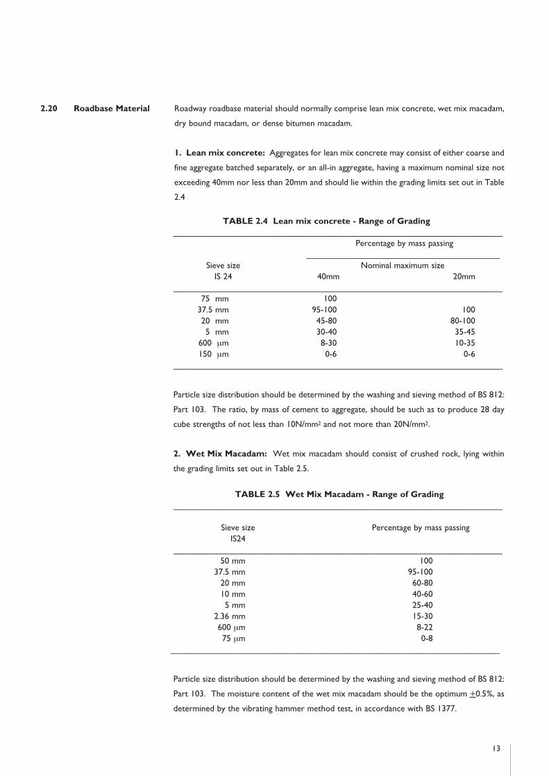
2.20 Roadbase Material Roadway roadbase material should normally comprise lean mix concrete, wet mix macadam,
dry bound macadam, or dense bitumen macadam.
1. Lean mix concrete: Aggregates for lean mix concrete may consist of either coarse and
fine aggregate batched separately, or an all-in aggregate, having a maximum nominal size not
exceeding 40mm nor less than 20mm and should lie within the grading limits set out in Table
2.4
TABLE 2.4 Lean mix concrete - Range of Grading____________________________________________________________________
Percentage by mass passing________________________________________
Sieve size Nominal maximum sizeIS 24 40mm 20mm
____________________________________________________________________75 mm 100
37.5 mm 95-100 10020 mm 45-80 80-1005 mm 30-40 35-45
600 µm 8-30 10-35150 µm 0-6 0-6
____________________________________________________________________
Particle size distribution should be determined by the washing and sieving method of BS 812:
Part 103. The ratio, by mass of cement to aggregate, should be such as to produce 28 day
cube strengths of not less than 10N/mm2 and not more than 20N/mm2.
2. Wet Mix Macadam: Wet mix macadam should consist of crushed rock, lying within
the grading limits set out in Table 2.5.
TABLE 2.5 Wet Mix Macadam - Range of Grading____________________________________________________________________
Sieve size Percentage by mass passingIS24
____________________________________________________________________50 mm 100
37.5 mm 95-10020 mm 60-8010 mm 40-605 mm 25-40
2.36 mm 15-30600 µm 8-2275 µm 0-8
____________________________________________________________________
Particle size distribution should be determined by the washing and sieving method of BS 812:
Part 103. The moisture content of the wet mix macadam should be the optimum +0.5%, as
determined by the vibrating hammer method test, in accordance with BS 1377.
13
3. Dry-bound Macadam: Dry-bound macadam should consist of coarse and fine
aggregate. The coarse aggregate should consist of crushed rock complying with the 50mm,
or the 40mm nominal sizes of BS 63 and the fine aggregate should all pass the 5mm IS sieve
size. The coarse aggregate should be compacted in 100mm layers and fine aggregate, as
required, vibrated into the voids of the coarse aggregate.
4. Dense Bitumen Macadam: Dense bitumen macadam should be 40mm nominal size
dense roadbase, in accordance with BS 4987: Part 1.
Roadbase materials should be compacted in accordance with Clause 705, 802, or 809 of the
Specification for Roadworks, as appropriate.
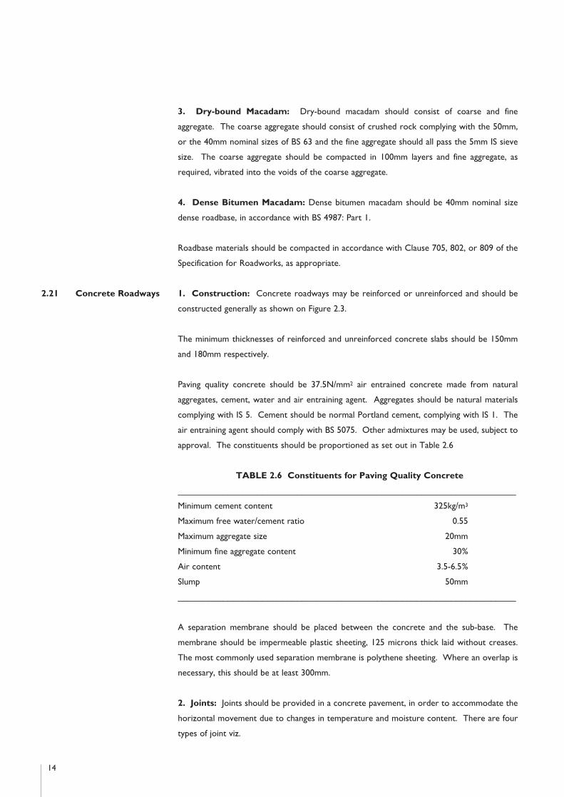
2.21 Concrete Roadways 1. Construction: Concrete roadways may be reinforced or unreinforced and should be
constructed generally as shown on Figure 2.3.
The minimum thicknesses of reinforced and unreinforced concrete slabs should be 150mm
and 180mm respectively.
Paving quality concrete should be 37.5N/mm2 air entrained concrete made from natural
aggregates, cement, water and air entraining agent. Aggregates should be natural materials
complying with IS 5. Cement should be normal Portland cement, complying with IS 1. The
air entraining agent should comply with BS 5075. Other admixtures may be used, subject to
approval. The constituents should be proportioned as set out in Table 2.6
TABLE 2.6 Constituents for Paving Quality Concrete
____________________________________________________________________
Minimum cement content 325kg/m3
Maximum free water/cement ratio 0.55
Maximum aggregate size 20mm
Minimum fine aggregate content 30%
Air content 3.5-6.5%
Slump 50mm
____________________________________________________________________
A separation membrane should be placed between the concrete and the sub-base. The
membrane should be impermeable plastic sheeting, 125 microns thick laid without creases.
The most commonly used separation membrane is polythene sheeting. Where an overlap is
necessary, this should be at least 300mm.
2. Joints: Joints should be provided in a concrete pavement, in order to accommodate the
horizontal movement due to changes in temperature and moisture content. There are four
types of joint viz.
14

15
Transverse contraction joints
Transverse expansion joints
Longitudinal joints
Formed contraction joints
Details for each of these joints are shown in Figures 2.4, 2.5, 2.6 and 2.7 respectively.
Maximum transverse joint spacing should be as shown in Table 2.7
TABLE 2.7 Maximum transverse joint spacing
____________________________________________________________________
Slab thickness Maximum
(mm) spacing (m)
Unreinforced ________________________________________
Concrete 180 - 200 4.5
201 - 250 5.0
____________________________________________________________________
Reinforcement, Maximum spacing (m),
long mesh to any slab thickness
BS: 4483
Reinforced Concrete ________________________________________
C283 15
C385 20
C503 25
____________________________________________________________________
The spacings in Table 2.7 refer to contraction joints. Transverse expansion joints would not
generally be required for roads constructed under summer conditions. However, for a road
constructed during the winter months, expansion joints are recommended. In order to avoid
uncertainty, it is considered good practice to provide expansion joints, irrespective of the
time of year laid. Transverse expansion joints should be provided at intervals of 60-75m,
where they would replace a transverse contraction joint.
Expansion joints should also be provided, to form small slabs around all manhole covers,
gullies and surface boxes occuring on the roadway. The slabs should be at least as large as
the external dimensions of the relevant chambers.
Transverse construction joints are required at the end of a day's work, or in the event of a
plant breakdown. All such joints should take the form of either a contraction or expansion
joint. In no instance should a construction joint be located closer than 2m from an existing
joint position. A formed contraction joint is detailed in Figure 2.7.
Roadways wider than 4m should have a central longitudinal joint.

16
25mmseal
compressible filler board its top routedout later to receive joint sealant
waterproof cap with compressible fillerdowel bars, covered over their lengthwith plastic sleeves, at 300mm centres
Reinforcement (if used) should have 50mm cover and terminate within 300 + 50mm of joint line
FIGURE 2.5: TRANSVERSE EXPANSION JOINT
Note (i) For concrete slabs up to 230mm deep the dowel bars should be 20mm diameter and 500mm long. Above this depth the bars should be 25mm diameter and 600mm long.
–
dowel bars, covered over their lengthwith plastic sleeves, at 300mm centresbottom crack inducer
Reinforcement (if used) should have 50mm cover and terminate within 300 + 50mm of joint line
Groove20mm
FIGURE 2.4: TRANSVERSE CONTRACTION JOINT
Note (i) Groove formed by vibrating a narrow strip into the plastic concrete. This strip is then removed and replaced by a temporary filler. Alternatively a preformed sealing strip can be inserted into the plastic concrete acting as both the top crack inducer and temporary joint. The top of the groove is later widened by sawing to 20mm and then sealed.
Note (ii) The combined depth of the top groove and bottom crack inducer should be between a quarter and a third of the slab depth. Alternatively a deep surface groove can be sawn to a depth between a quarter and a third of the slab depth and the bottom crack inducer omitted. This is the preferred option.
Note (iii) For concrete slabs up to 230mm deep the dowel bars should be 20mm diameter and 500mm long. Above this depth the bars should be 25mm diameter and 600mm long.
–

Sawing of joint grooves should be undertaken as soon as possible after the concrete has
hardened sufficiently to enable a sharp edged groove to be produced, without disrupting the
concrete and before random cracks develop in the slab. This would usually be within 6 to 24
hours after the concrete is poured. The grooves should be between 1/4 and 1/3 the depth
of the slab and of any convenient width not less than 3mm. The groove can be widened by
sawing at this stage, or later, to accommodate the joint sealant.
Expansion joint filler should be compressible board 25mm thick, for the full depth of the
concrete. The top of the filler board should be routed out later, to a depth of 25mm, in order
to receive the joint sealant.
Dowel bars and tie bars should be Grade 250 steel, complying with BS 4449 and should be
free from oil, dirt, loose scale and rust. Dowel bars should be straight, free of burrs and other
17
12mm tie bars (cast into first slab)– 900mm long at 600mm centres
Reinforcement (if used) should have 50mm cover and terminate within 60 + 20mm of joint line
Pre-formed strip stuck to edge of hardenedconcrete slab as joint sealer: the top of the stripshould be 3mm below the level of the slab
FIGURE 2.6: LONGITUDINAL JOINT
–
Reinforcement (if used) should have 50mm cover and terminate within 300 + 50mm of joint line
Note (i) For concrete slabs up to 230mm deep the dowel bars should be 20mm diameter and 500mm long.Above this depth the bars should be 25mm diameter and 600mm long.
dowel bars, covered over their lengthwith plastic sleeves, at 300mm centres
Pre-formed strip stuck to edge of hardenedconcrete slab as joint sealer: the top of the stripshould be 3mm below the level of the slab
–
FIGURE 2.7: FORMED CONTRACTION JOINT
–

18
irregularities, with the sliding end sawn. Dowel bars should be debonded over their length
with a tough, durable plastic sheath of average thickness not greater than 1.25mm. For
expansion joints, the expansion space available in the waterproof cap should be 10mm greater
than the thickness of the joint filler board.
Joint grooves should be sealed with a hot applied joint-sealing compound complying with BS
2499 Type A2 and the finished surface of the seal should be 3mm below the surface level of
the concrete.
Other expansion joint filling or sealing materials, or other debonding agents may be used,
subject to approval.
3. Reinforcement: Where reinforced concrete is used, the reinforcement should be long
mesh steel fabric, complying with BS 4483 and should be free from loose mill scale, rust, dirt,
oil, paint or grease. The minimum weight of reinforcement should be 2.61 kg/m2. The
reinforcement should have 50mm minimum cover from the surface and should terminate
between 250 and 350mm from any transverse joint and between 40 and 80mm from a
longitudinal joint. The reinforcement should terminate between 100 and 150mm from the
edges of the slab. Reinforcing mats should overlap such that the transverse wire of one mat
would lie within the last complete mesh of the previous mat and the overlap should be at least
450mm.
2.22 Block Paving Block paving roadways should be constructed generally as shown on Figure 2.3. The layout
Roadways and structural design of the pavement is subject to approval.
The structural design of pavements constructed with clay or concrete block pavers, should
comply with the requirements of BS 7533.
Clay and calcium silicate pavers should comply with BS 6677: Part 1, type PB with chamfers.
200 x 100 x 65mm pavers are generally the preferred size.
Concrete block pavers should comply with BS 6717: Part 1, type R. 200 x 100 x 80mm pavers
are generally the preferred size.
Horizontal interlock should be given to the paving, either by the use of shaped blocks, or by
laying rectangular blocks in a herringbone pattern. At the edge of the pavement, restraint
should be provided, in order to prevent the pavers and the laying course from migrating
outwards and losing interlock.
Clay and calcium silicate pavers should be laid in accordance with BS 6677: Parts 2 & 3.
Concrete block pavers should be laid in accordance with BS 6717: Part 3.
Laying course sand and jointing sand should comply with gradings C and F in Table 5 of IS 5
respectively.

2.23 Flexible Roadways Flexible roadways should be constructed generally as shown on Figure 2.3.
The minimum roadbase thickness should be 150mm, except for dense bitumen macadam
roadbase, which should have a minimum thickness at any point, of 80mm.
The Contractor may use either the sub-base, or the roadbase appropriately strengthened, for
construction plant and traffic.
The requirements for so using the sub-base, are set out in clause 2.17 above. Any damage
caused by construction traffic should be remedied, as approved, before laying of the roadbase.
Alternatively, the roadbase may be used by construction traffic, provided it is increased in
thickness by 50mm and surface dressed in accordance with clause 2.24 below. Damage
caused by construction traffic should be remedied, as approved, before laying of the surface
course. Contaminated materials should be made good by cleaning; if this proves impractical
the layer should be removed and replaced.
Roadway surfacing should consist of one of the following:
1. Two courses, consisting of a basecourse, 40mm minimum thickness at any point, of 20mm
nominal size dense basecourse bitumen macadam and a wearing course, 25mm minimum
thickness at any point, of 10mm nominal size close graded wearing course bitumen macadam,
both of which should comply with BS 4987.
2. A combined wearing course and basecourse, 80mm thickness at any point, consisting of
40mm nominal size single course bitumen macadam, complying with BS 4987.
2.24 Surface Dressing Surface dressing should be carried out in accordance with the manual "Surface Dressing"
published by the Department of the Environment. The binder should be cutback bitumen or
cationic bitumen emulsion, complying with the specifications issued by the Department of the
Environment. Other binders may be used, subject to approval.
Cutback bitumen should be of the appropriate grade recommended in the manual. Cationic
bitumen emulsion should have a nominal bitumen content of 70%. The binder should be
spread at the appropriate rate recommended in the manual. Chippings should be of a single
size (as approved by the local authority), cubical in shape and should comply with the
requirements of Table 4 of the manual.
2.25 Footways Footways should have a sub-base, of minimum thickness 100mm, complying with clause 2.19
above and should normally be of in-situ concrete construction, 100mm in depth generally, but
increasing to 150mm where there is vehicular access. Other forms of footway construction
are subject to approval.
19

The minimum footway width should normally be 2m. Where isolated obstructions occur on
footways, the minimum clear width at the obstruction should be 1.2m. Footways should have
a cross slope of 2.5% and where adjacent to roadways, this slope should be towards the
roadway. Joints should be formed in a straight line, at right angles to the footway, at a
maximum spacing of 3m and each joint should include a double layer of roofing felt, complying
with IS 36, for the full depth of the joint.
A separation membrane, as specified in clause 2.21 above, should be placed between the
concrete and the sub-base.
Concrete should be air entrained paving quality, as specified in Table 2.6 of clause 2.21 above.
2.26 Kerbs At roadway edges, kerbs should show between 100mm and 150mm above the channel,
except at vehicular accesses, where they should be reduced to 25mm over the channel and
at wheelchair and pram accesses where an upstand of 10mm should be provided. The
footway slope at such dished kerbs should not normally exceed 7%.
Cast-in-situ concrete kerbs should be 300mm deep by 225mm wide, laid on a 100mm sub-
base which should be haunched. Concrete should be air entrained, as specified in Table 2.6
of clause 2.21 above.
Precast kerbs should be 250mm by 125mm, complying with IS 146 and should be laid on a
100mm thick by 300mm wide concrete bed and haunch.
Alternative kerb types at roadway edges are subject to approval.
2.27 Cement Cement should comply with IS 1.
2.28 Concrete Aggregates Coarse and fine aggregates from natural sources, for concrete, should comply with IS 5.
20

3.1 Compliance Drainage works should comply generally with the requirements of BS 8005: Part 1, BS 8301
and the Specification for Roadworks.
3.2 Separate Systems Some public sewers carry foul water and surface water (combined systems) in the same pipe.
All new drainage systems should be designed and constructed on the basis of a separate
system, even where draining into a combined system.
3.3 Pipe Types The following pipes and fittings may be used for foul and surface water sewers and drains:
1. Unplasticized polyvinylchloride (PVC-U) pipes and fittings, in accordance with the
requirements of IS 424.
2. Spigot and socket concrete pipes, in accordance with the requirements of IS 6.
3. Clayware pipes and fittings, in accordance with the requirements of IS EN 295.
4. Glass reinforced plastics (GRP) pipes and fittings, in accordance with the requirements
of BS 5480.
5. Glass composite concrete (GCC) pipes and fittings, in accordance with the requirements
of BS 5911: Part 101.
Joint types and materials are subject to approval.
Rebated concrete pipes and fittings, in accordance with the requirements of BS 5911: Part
100, may be used for surface water sewers and drains only. Joints should incorporate an
elastomeric ring in compliance with Type D of BS 2494.
Other pipes and fittings may be used, subject to approval.
3.4 Pipe Sizes & Performance criteria for protection against surcharge and flooding should be determined by
Gradients - Surface the local authority.
Water
The area to be taken into account, should be the total area of the roofs, together with the
total area of paving contributing to the pipe system. Paving from which the run-off flows onto
permeable surfaces should not be included. Where there is a possibility that the run-off from
unpaved areas might cause ponding, or contribute significantly to the pipe flows, proposals for
the drainage of such areas are subject to approval.
Surface run-off (l/s) should be calculated by means of the Modified Rational Method
(Wallingford Procedure).
21
Section 3: Sewers and Drains

Q = Ap x i x Cr x Cv x 2.78
where
Q = Rate of run-off (l/s)
Ap = Impermeable area (ha)
i = Intensity of rainfall (mm/h)
Cr = Routing coefficient
Cv = Volumetric run-off coefficient
For areas which require a main surface water drain of up to 200m in length, rainfall intensities
(i) of 75mm per hour for roof surfaces and 50 mm per hour for paved surfaces may be used.
For larger areas, the rainfall intensity/duration/frequency relationship requires to be
established, having regard to such local rainfall records as are available.
Recommended storm return periods for the design of drainage pipework, within the context
of this publication, are set out in Table 3.1.
TABLE 3.1 Recommended Storm Return Periods for the
Design of Drainage Pipework
____________________________________________________________________
Type of Site Return Period Years
____________________________________________________________________
Sites with average surface gradient greater than 1% 1
Sites with average surface gradient of 1% or less 2
Sites where consequences of flooding are severe 5
____________________________________________________________________
It may be assumed that the maximum discharge of storm water from an area occurs when
the duration of the storm is equal to the time of concentration (t) of the area. The time of
concentration is the longest time taken for the rain falling on the area to reach the drain, plus
the time taken to reach the point of concentration.
t = time of entry + length of drain
full bore velocity of flow
The time of entry may be regarded as representing the delay and attenuation of flow over the
ground surface. Time of entry generally lies in the range of 4 to 8 minutes, with the larger
figure applicable to a relatively flat subcatchment and the smaller value to relatively steep
subcatchments. (Subcatchment refers to the area contributing to each individual pipe length).
Particular conditions may warrant a time of entry outside this range.
22
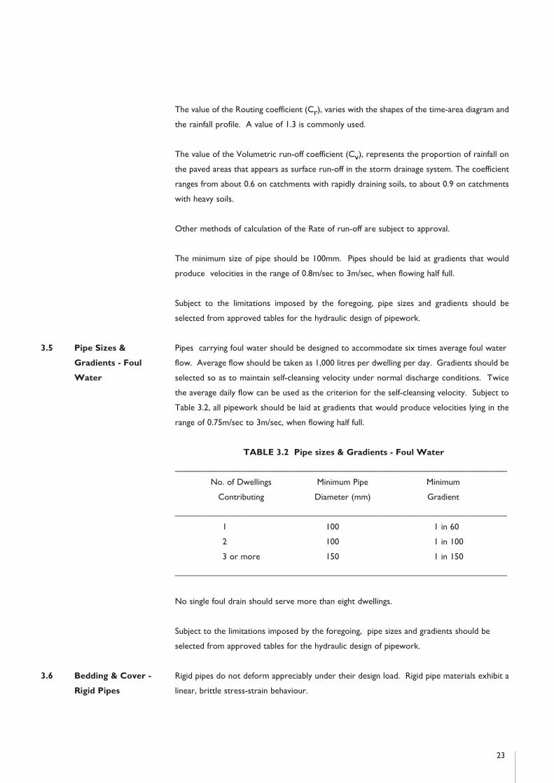
The value of the Routing coefficient (Cr), varies with the shapes of the time-area diagram and
the rainfall profile. A value of 1.3 is commonly used.
The value of the Volumetric run-off coefficient (Cv), represents the proportion of rainfall on
the paved areas that appears as surface run-off in the storm drainage system. The coefficient
ranges from about 0.6 on catchments with rapidly draining soils, to about 0.9 on catchments
with heavy soils.
Other methods of calculation of the Rate of run-off are subject to approval.
The minimum size of pipe should be 100mm. Pipes should be laid at gradients that would
produce velocities in the range of 0.8m/sec to 3m/sec, when flowing half full.
Subject to the limitations imposed by the foregoing, pipe sizes and gradients should be
selected from approved tables for the hydraulic design of pipework.
3.5 Pipe Sizes & Pipes carrying foul water should be designed to accommodate six times average foul water
Gradients - Foul flow. Average flow should be taken as 1,000 litres per dwelling per day. Gradients should be
Water selected so as to maintain self-cleansing velocity under normal discharge conditions. Twice
the average daily flow can be used as the criterion for the self-cleansing velocity. Subject to
Table 3.2, all pipework should be laid at gradients that would produce velocities lying in the
range of 0.75m/sec to 3m/sec, when flowing half full.
TABLE 3.2 Pipe sizes & Gradients - Foul Water
____________________________________________________________________
No. of Dwellings Minimum Pipe Minimum
Contributing Diameter (mm) Gradient
____________________________________________________________________
1 100 1 in 60
2 100 1 in 100
3 or more 150 1 in 150
____________________________________________________________________
No single foul drain should serve more than eight dwellings.
Subject to the limitations imposed by the foregoing, pipe sizes and gradients should be
selected from approved tables for the hydraulic design of pipework.
3.6 Bedding & Cover - Rigid pipes do not deform appreciably under their design load. Rigid pipe materials exhibit a
Rigid Pipes linear, brittle stress-strain behaviour.
23

The load carrying capacity of a rigid pipe is dependant on three main factors - the minimum
crushing strength of the pipe, the class of bedding used and the uniformity of the support
provided by the foundation along the pipeline.
Bedding and cover requirements for rigid drainage pipes are set out in Figure 3.1 and Table
3.3. It should be noted that Class D bedding should not be used, unless accurate trimming
can ensure full bearing of the pipe on the trench floor. Class F bedding is generally suitable in
all soil conditions, but measures may be required to prevent ground water flow in the
trenches, during construction.
Selected fill should be free from stones larger than 37.5mm, lumps of clay over 75mm, timber,
frozen material and vegetable matter.
Granular material should be either 14mm to 5mm graded aggregate, or 10mm single sized
aggregate, complying with the requirements of IS 5: Part 1: 1990, Table 7 and should have a
Compaction Factor value not greater than 0.2 when measured in accordance with BS 8301:
1985, Appendix D.
24
150min. 150min.
100min. 100min.������������������������������
@@@@@@@@@@@@@@@@@@@@@@@@@@@@@@
������������������������������
ÀÀÀÀÀÀÀÀÀÀÀÀÀÀÀÀÀÀÀÀÀÀÀÀÀÀÀÀÀÀ
������������������������������
@@@@@@@@@@@@@@@@@@@@@@@@@@@@@@
������������������������������
ÀÀÀÀÀÀÀÀÀÀÀÀÀÀÀÀÀÀÀÀÀÀÀÀÀÀÀÀÀÀ
������������������������������
@@@@@@@@@@@@@@@@@@@@@@@@@@@@@@
������������������������������
ÀÀÀÀÀÀÀÀÀÀÀÀÀÀÀÀÀÀÀÀÀÀÀÀÀÀÀÀÀÀ
������������������������������
@@@@@@@@@@@@@@@@@@@@@@@@@@@@@@
������������������������������
ÀÀÀÀÀÀÀÀÀÀÀÀÀÀÀÀÀÀÀÀÀÀÀÀÀÀÀÀÀÀ
������������������������������
@@@@@@@@@@@@@@@@@@@@@@@@@@@@@@
������������������������������
ÀÀÀÀÀÀÀÀÀÀÀÀÀÀÀÀÀÀÀÀÀÀÀÀÀÀÀÀÀÀ
������������������������������
@@@@@@@@@@@@@@@@@@@@@@@@@@@@@@
������������������������������
ÀÀÀÀÀÀÀÀÀÀÀÀÀÀÀÀÀÀÀÀÀÀÀÀÀÀÀÀÀÀ
������������������������������
@@@@@@@@@@@@@@@@@@@@@@@@@@@@@@
������������������������������
ÀÀÀÀÀÀÀÀÀÀÀÀÀÀÀÀÀÀÀÀÀÀÀÀÀÀÀÀÀÀ
������������������������������
@@@@@@@@@@@@@@@@@@@@@@@@@@@@@@
������������������������������
ÀÀÀÀÀÀÀÀÀÀÀÀÀÀÀÀÀÀÀÀÀÀÀÀÀÀÀÀÀÀ
������������������������������
@@@@@@@@@@@@@@@@@@@@@@@@@@@@@@
������������������������������
ÀÀÀÀÀÀÀÀÀÀÀÀÀÀÀÀÀÀÀÀÀÀÀÀÀÀÀÀÀÀ
������������������������������
@@@@@@@@@@@@@@@@@@@@@@@@@@@@@@
������������������������������
ÀÀÀÀÀÀÀÀÀÀÀÀÀÀÀÀÀÀÀÀÀÀÀÀÀÀÀÀÀÀ
������������������������������
@@@@@@@@@@@@@@@@@@@@@@@@@@@@@@
������������������������������
ÀÀÀÀÀÀÀÀÀÀÀÀÀÀÀÀÀÀÀÀÀÀÀÀÀÀÀÀÀÀ
������������������������������
@@@@@@@@@@@@@@@@@@@@@@@@@@@@@@
������������������������������
ÀÀÀÀÀÀÀÀÀÀÀÀÀÀÀÀÀÀÀÀÀÀÀÀÀÀÀÀÀÀ
������������������������������
@@@@@@@@@@@@@@@@@@@@@@@@@@@@@@
������������������������������
ÀÀÀÀÀÀÀÀÀÀÀÀÀÀÀÀÀÀÀÀÀÀÀÀÀÀÀÀÀÀ
������������������������������
@@@@@@@@@@@@@@@@@@@@@@@@@@@@@@
������������������������������
ÀÀÀÀÀÀÀÀÀÀÀÀÀÀÀÀÀÀÀÀÀÀÀÀÀÀÀÀÀÀ
������������������������������
@@@@@@@@@@@@@@@@@@@@@@@@@@@@@@
������������������������������
ÀÀÀÀÀÀÀÀÀÀÀÀÀÀÀÀÀÀÀÀÀÀÀÀÀÀÀÀÀÀ
������������������������������
@@@@@@@@@@@@@@@@@@@@@@@@@@@@@@
������������������������������
ÀÀÀÀÀÀÀÀÀÀÀÀÀÀÀÀÀÀÀÀÀÀÀÀÀÀÀÀÀÀ
������������������������������
150min.
Bc/2
Bc��������������������������������������������������
@@@@@@@@@@@@@@@@@@@@@@@@@@@@@@@@@@@@@@@@@@@@@@@@@@
��������������������������������������������������
ÀÀÀÀÀÀÀÀÀÀÀÀÀÀÀÀÀÀÀÀÀÀÀÀÀÀÀÀÀÀÀÀÀÀÀÀÀÀÀÀÀÀÀÀÀÀÀÀÀÀ
��������������������������������������������������
@@@@@@@@@@@@@@@@@@@@@@@@@@@@@@@@@@@@@@@@@@@@@@@@@@
��������������������������������������������������
ÀÀÀÀÀÀÀÀÀÀÀÀÀÀÀÀÀÀÀÀÀÀÀÀÀÀÀÀÀÀÀÀÀÀÀÀÀÀÀÀÀÀÀÀÀÀÀÀÀÀ
��������������������������������������������������
@@@@@@@@@@@@@@@@@@@@@@@@@@@@@@@@@@@@@@@@@@@@@@@@@@
��������������������������������������������������
ÀÀÀÀÀÀÀÀÀÀÀÀÀÀÀÀÀÀÀÀÀÀÀÀÀÀÀÀÀÀÀÀÀÀÀÀÀÀÀÀÀÀÀÀÀÀÀÀÀÀ
��������������������������������������������������
@@@@@@@@@@@@@@@@@@@@@@@@@@@@@@@@@@@@@@@@@@@@@@@@@@
��������������������������������������������������
ÀÀÀÀÀÀÀÀÀÀÀÀÀÀÀÀÀÀÀÀÀÀÀÀÀÀÀÀÀÀÀÀÀÀÀÀÀÀÀÀÀÀÀÀÀÀÀÀÀÀ
��������������������������������������������������
@@@@@@@@@@@@@@@@@@@@@@@@@@@@@@@@@@@@@@@@@@@@@@@@@@
��������������������������������������������������
ÀÀÀÀÀÀÀÀÀÀÀÀÀÀÀÀÀÀÀÀÀÀÀÀÀÀÀÀÀÀÀÀÀÀÀÀÀÀÀÀÀÀÀÀÀÀÀÀÀÀ
��������������������������������������������������
@@@@@@@@@@@@@@@@@@@@@@@@@@@@@@@@@@@@@@@@@@@@@@@@@@
��������������������������������������������������
ÀÀÀÀÀÀÀÀÀÀÀÀÀÀÀÀÀÀÀÀÀÀÀÀÀÀÀÀÀÀÀÀÀÀÀÀÀÀÀÀÀÀÀÀÀÀÀÀÀÀ
��������������������������������������������������
@@@@@@@@@@@@@@@@@@@@@@@@@@@@@@@@@@@@@@@@@@@@@@@@@@
��������������������������������������������������
ÀÀÀÀÀÀÀÀÀÀÀÀÀÀÀÀÀÀÀÀÀÀÀÀÀÀÀÀÀÀÀÀÀÀÀÀÀÀÀÀÀÀÀÀÀÀÀÀÀÀ
��������������������������������������������������
@@@@@@@@@@@@@@@@@@@@@@@@@@@@@@@@@@@@@@@@@@@@@@@@@@
��������������������������������������������������
ÀÀÀÀÀÀÀÀÀÀÀÀÀÀÀÀÀÀÀÀÀÀÀÀÀÀÀÀÀÀÀÀÀÀÀÀÀÀÀÀÀÀÀÀÀÀÀÀÀÀ
��������������������������������������������������
@@@@@@@@@@@@@@@@@@@@@@@@@@@@@@@@@@@@@@@@@@@@@@@@@@
��������������������������������������������������
ÀÀÀÀÀÀÀÀÀÀÀÀÀÀÀÀÀÀÀÀÀÀÀÀÀÀÀÀÀÀÀÀÀÀÀÀÀÀÀÀÀÀÀÀÀÀÀÀÀÀ
��������������������������������������������������
@@@@@@@@@@@@@@@@@@@@@@@@@@@@@@@@@@@@@@@@@@@@@@@@@@
��������������������������������������������������
ÀÀÀÀÀÀÀÀÀÀÀÀÀÀÀÀÀÀÀÀÀÀÀÀÀÀÀÀÀÀÀÀÀÀÀÀÀÀÀÀÀÀÀÀÀÀÀÀÀÀ
��������������������������������������������������
@@@@@@@@@@@@@@@@@@@@@@@@@@@@@@@@@@@@@@@@@@@@@@@@@@
��������������������������������������������������
ÀÀÀÀÀÀÀÀÀÀÀÀÀÀÀÀÀÀÀÀÀÀÀÀÀÀÀÀÀÀÀÀÀÀÀÀÀÀÀÀÀÀÀÀÀÀÀÀÀÀ
��������������������������������������������������
@@@@@@@@@@@@@@@@@@@@@@@@@@@@@@@@@@@@@@@@@@@@@@@@@@
��������������������������������������������������
ÀÀÀÀÀÀÀÀÀÀÀÀÀÀÀÀÀÀÀÀÀÀÀÀÀÀÀÀÀÀÀÀÀÀÀÀÀÀÀÀÀÀÀÀÀÀÀÀÀÀ
��������������������������������������������������
@@@@@@@@@@@@@@@@@@@@@@@@@@@@@@@@@@@@@@@@@@@@@@@@@@
��������������������������������������������������
ÀÀÀÀÀÀÀÀÀÀÀÀÀÀÀÀÀÀÀÀÀÀÀÀÀÀÀÀÀÀÀÀÀÀÀÀÀÀÀÀÀÀÀÀÀÀÀÀÀÀ
��������������������������������������������������
@@@@@@@@@@@@@@@@@@@@@@@@@@@@@@@@@@@@@@@@@@@@@@@@@@
��������������������������������������������������
ÀÀÀÀÀÀÀÀÀÀÀÀÀÀÀÀÀÀÀÀÀÀÀÀÀÀÀÀÀÀÀÀÀÀÀÀÀÀÀÀÀÀÀÀÀÀÀÀÀÀ
��������������������������������������������������
@@@@@@@@@@@@@@@@@@@@@@@@@@@@@@@@@@@@@@@@@@@@@@@@@@
��������������������������������������������������
ÀÀÀÀÀÀÀÀÀÀÀÀÀÀÀÀÀÀÀÀÀÀÀÀÀÀÀÀÀÀÀÀÀÀÀÀÀÀÀÀÀÀÀÀÀÀÀÀÀÀ
��������������������������������������������������
@@@@@@@@@@@@@@@@@@@@@@@@@@@@@@@@@@@@@@@@@@@@@@@@@@
��������������������������������������������������
ÀÀÀÀÀÀÀÀÀÀÀÀÀÀÀÀÀÀÀÀÀÀÀÀÀÀÀÀÀÀÀÀÀÀÀÀÀÀÀÀÀÀÀÀÀÀÀÀÀÀ
��������������������������������������������������
CLASS D CLASS F
FIGURE 3.1: BEDDING AND SURROUND FOR RIGID DRAINAGE PIPES
CLASS B
Dimensions are in millimiteres
Selected Fill
Granular material
����������������
@@@@@@@@@@@@@@@@
����������������
ÀÀÀÀÀÀÀÀÀÀÀÀÀÀÀÀ
����������������
@@@@@@@@@@@@@@@@
����������������
ÀÀÀÀÀÀÀÀÀÀÀÀÀÀÀÀ
����������������
@@@@@@@@@@@@@@@@
����������������
ÀÀÀÀÀÀÀÀÀÀÀÀÀÀÀÀ
����������������
@@@@@@@@@@@@@@@@
����������������
ÀÀÀÀÀÀÀÀÀÀÀÀÀÀÀÀ
����������������
@@@@@@@@@@@@@@@@
����������������
ÀÀÀÀÀÀÀÀÀÀÀÀÀÀÀÀ
����������������
@@@@@@@@@@@@@@@@
����������������
ÀÀÀÀÀÀÀÀÀÀÀÀÀÀÀÀ
����������������
@@@@@@@@@@@@@@@@
����������������
ÀÀÀÀÀÀÀÀÀÀÀÀÀÀÀÀ
����������������
@@@@@@@@@@@@@@@@
����������������
ÀÀÀÀÀÀÀÀÀÀÀÀÀÀÀÀ
����������������
@@@@@@@@@@@@@@@@
����������������
ÀÀÀÀÀÀÀÀÀÀÀÀÀÀÀÀ
����������������
@@@@@@@@@@@@@@@@
����������������
ÀÀÀÀÀÀÀÀÀÀÀÀÀÀÀÀ
����������������
@@@@@@@@@@@@@@@@
����������������
ÀÀÀÀÀÀÀÀÀÀÀÀÀÀÀÀ
����������������
@@@@@@@@@@@@@@@@
����������������
ÀÀÀÀÀÀÀÀÀÀÀÀÀÀÀÀ
����������������
@@@@@@@@@@@@@@@@
����������������
ÀÀÀÀÀÀÀÀÀÀÀÀÀÀÀÀ
����������������
@@@@@@@@@@@@@@@@
����������������
ÀÀÀÀÀÀÀÀÀÀÀÀÀÀÀÀ
����������������
@@@@@@@@@@@@@@@@
����������������
ÀÀÀÀÀÀÀÀÀÀÀÀÀÀÀÀ
����������������
@@@@@@@@@@@@@@@@
����������������
ÀÀÀÀÀÀÀÀÀÀÀÀÀÀÀÀ
����������������
�@�À�@�À�@�À�@�À��@�À�@�À�@�À�@�À���@@��ÀÀ��@@��ÀÀ��@@��ÀÀ��@@��ÀÀ������@@@@����ÀÀÀÀ����@@@@����ÀÀÀÀ����@@@@����ÀÀÀÀ����@@@@����ÀÀÀÀ������@@��ÀÀ��@@��ÀÀ��@@��ÀÀ��@@��ÀÀ����@@��ÀÀ��@@��ÀÀ��@@��ÀÀ��@@��ÀÀ������@@@@����ÀÀÀÀ����@@@@����ÀÀÀÀ����@@@@����ÀÀÀÀ����@@@@����ÀÀÀÀ��������@@@@����ÀÀÀÀ����@@@@����ÀÀÀÀ����@@@@����ÀÀÀÀ����@@@@����ÀÀÀÀ����

TABLE 3.3 Limits of cover in metres for standard rigid pipes in any
width of trench
____________________________________________________________________
Gardens Light traffic Roads
____________________________________________________________________
Pipe Bedding Min Max Min Max
Diameter Class
____________________________________________________________________
100mm D 0.6 4.2 1.2 4.1
100mm F 0.6 5.8 1.2 5.8
100mm B 0.6 7.4 1.2 7.4
150mm D 0.6 2.7 1.2 2.5
150mm F 0.6 3.9 1.2 3.8
150mm B 0.6 5.0 1.2 5.0
225mm D - - - -
225mm F 0.6 2.5 1.2 2.1
225mm B 0.6 3.3 1.2 3.2
300mm D - - - -
300mm F 0.6 2.2 - -
300mm B 0.6 2.6 1.2 2.4
____________________________________________________________________
Pipes laid in open spaces should have a minimum cover of 0.9m.
Where it is not possible to achieve the minimum cover stipulated in Table 3.3, pipes should
be bedded and surrounded in concrete, 150mm thick, Class E, in accordance with Clause
1502 of the Specification for Roadworks.
For depths of cover greater than the maxima stipulated in Table 3.3, pipes with a higher
crushing strength and/or bedding with a higher bedding factor are required, subject to
approval.
3.7 Bedding & Cover - Flexible pipes deform under load and the extent of this deformation depends upon the
Flexible Pipes stiffness of the pipe and the compaction of the immediately surrounding fill. The materials
for these pipes exhibit ductile stress-strain characteristics.
A flexible pipe derives its load bearing capacity from the pipe stiffness and the passive
resistance developed in the surrounding materials. Bedding and surround requirements for
flexible pipes are shown in Figure 3.2.
In the case of Vee Trench excavation, a sub-trench should be dug as shown in Figure 3.2.
Otherwise, the form of construction is the same as that of the Typical Trench case.
Flexible pipes should be laid with a minimum cover of 1.2m in roads and driveways, 0.9m in
open spaces and footpaths not adjacent to roadways and 0.6m in gardens. Where it is not
25
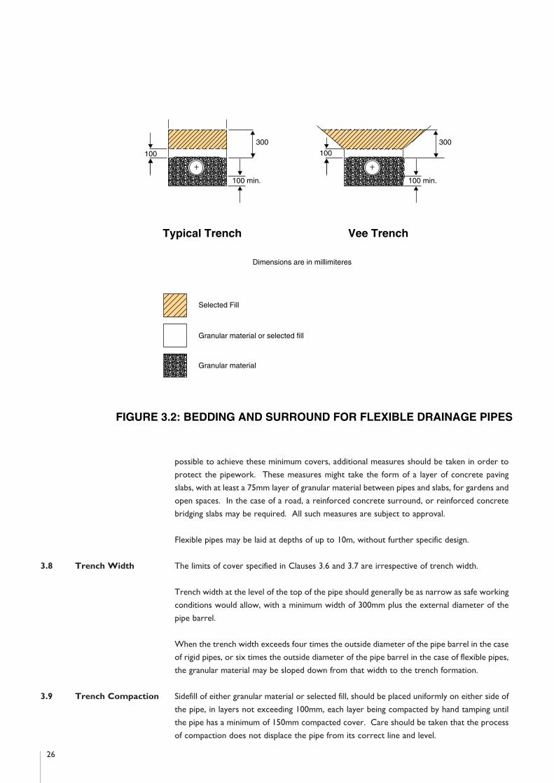
possible to achieve these minimum covers, additional measures should be taken in order to
protect the pipework. These measures might take the form of a layer of concrete paving
slabs, with at least a 75mm layer of granular material between pipes and slabs, for gardens and
open spaces. In the case of a road, a reinforced concrete surround, or reinforced concrete
bridging slabs may be required. All such measures are subject to approval.
Flexible pipes may be laid at depths of up to 10m, without further specific design.
3.8 Trench Width The limits of cover specified in Clauses 3.6 and 3.7 are irrespective of trench width.
Trench width at the level of the top of the pipe should generally be as narrow as safe working
conditions would allow, with a minimum width of 300mm plus the external diameter of the
pipe barrel.
When the trench width exceeds four times the outside diameter of the pipe barrel in the case
of rigid pipes, or six times the outside diameter of the pipe barrel in the case of flexible pipes,
the granular material may be sloped down from that width to the trench formation.
3.9 Trench Compaction Sidefill of either granular material or selected fill, should be placed uniformly on either side of
the pipe, in layers not exceeding 100mm, each layer being compacted by hand tamping until
the pipe has a minimum of 150mm compacted cover. Care should be taken that the process
of compaction does not displace the pipe from its correct line and level.
26
����������������������������������������
@@@@@@@@@@@@@@@@@@@@@@@@@@@@@@@@@@@@@@@@
����������������������������������������
ÀÀÀÀÀÀÀÀÀÀÀÀÀÀÀÀÀÀÀÀÀÀÀÀÀÀÀÀÀÀÀÀÀÀÀÀÀÀÀÀ
����������������������������������������
@@@@@@@@@@@@@@@@@@@@@@@@@@@@@@@@@@@@@@@@
����������������������������������������
ÀÀÀÀÀÀÀÀÀÀÀÀÀÀÀÀÀÀÀÀÀÀÀÀÀÀÀÀÀÀÀÀÀÀÀÀÀÀÀÀ
����������������������������������������
@@@@@@@@@@@@@@@@@@@@@@@@@@@@@@@@@@@@@@@@
����������������������������������������
ÀÀÀÀÀÀÀÀÀÀÀÀÀÀÀÀÀÀÀÀÀÀÀÀÀÀÀÀÀÀÀÀÀÀÀÀÀÀÀÀ
����������������������������������������
@@@@@@@@@@@@@@@@@@@@@@@@@@@@@@@@@@@@@@@@
����������������������������������������
ÀÀÀÀÀÀÀÀÀÀÀÀÀÀÀÀÀÀÀÀÀÀÀÀÀÀÀÀÀÀÀÀÀÀÀÀÀÀÀÀ
����������������������������������������
@@@@@@@@@@@@@@@@@@@@@@@@@@@@@@@@@@@@@@@@
����������������������������������������
ÀÀÀÀÀÀÀÀÀÀÀÀÀÀÀÀÀÀÀÀÀÀÀÀÀÀÀÀÀÀÀÀÀÀÀÀÀÀÀÀ
����������������������������������������
@@@@@@@@@@@@@@@@@@@@@@@@@@@@@@@@@@@@@@@@
����������������������������������������
ÀÀÀÀÀÀÀÀÀÀÀÀÀÀÀÀÀÀÀÀÀÀÀÀÀÀÀÀÀÀÀÀÀÀÀÀÀÀÀÀ
����������������������������������������
@@@@@@@@@@@@@@@@@@@@@@@@@@@@@@@@@@@@@@@@
����������������������������������������
ÀÀÀÀÀÀÀÀÀÀÀÀÀÀÀÀÀÀÀÀÀÀÀÀÀÀÀÀÀÀÀÀÀÀÀÀÀÀÀÀ
����������������������������������������
@@@@@@@@@@@@@@@@@@@@@@@@@@@@@@@@@@@@@@@@
����������������������������������������
ÀÀÀÀÀÀÀÀÀÀÀÀÀÀÀÀÀÀÀÀÀÀÀÀÀÀÀÀÀÀÀÀÀÀÀÀÀÀÀÀ
����������������������������������������
@@@@@@@@@@@@@@@@@@@@@@@@@@@@@@@@@@@@@@@@
����������������������������������������
ÀÀÀÀÀÀÀÀÀÀÀÀÀÀÀÀÀÀÀÀÀÀÀÀÀÀÀÀÀÀÀÀÀÀÀÀÀÀÀÀ
����������������������������������������
@@@@@@@@@@@@@@@@@@@@@@@@@@@@@@@@@@@@@@@@
����������������������������������������
ÀÀÀÀÀÀÀÀÀÀÀÀÀÀÀÀÀÀÀÀÀÀÀÀÀÀÀÀÀÀÀÀÀÀÀÀÀÀÀÀ
����������������������������������������
@@@@@@@@@@@@@@@@@@@@@@@@@@@@@@@@@@@@@@@@
����������������������������������������
ÀÀÀÀÀÀÀÀÀÀÀÀÀÀÀÀÀÀÀÀÀÀÀÀÀÀÀÀÀÀÀÀÀÀÀÀÀÀÀÀ
����������������������������������������
@@@@@@@@@@@@@@@@@@@@@@@@@@@@@@@@@@@@@@@@
����������������������������������������
ÀÀÀÀÀÀÀÀÀÀÀÀÀÀÀÀÀÀÀÀÀÀÀÀÀÀÀÀÀÀÀÀÀÀÀÀÀÀÀÀ
����������������������������������������
@@@@@@@@@@@@@@@@@@@@@@@@@@@@@@@@@@@@@@@@
����������������������������������������
ÀÀÀÀÀÀÀÀÀÀÀÀÀÀÀÀÀÀÀÀÀÀÀÀÀÀÀÀÀÀÀÀÀÀÀÀÀÀÀÀ
����������������������������������������
@@@@@@@@@@@@@@@@@@@@@@@@@@@@@@@@@@@@@@@@
����������������������������������������
ÀÀÀÀÀÀÀÀÀÀÀÀÀÀÀÀÀÀÀÀÀÀÀÀÀÀÀÀÀÀÀÀÀÀÀÀÀÀÀÀ
����������������������������������������
@@@@@@@@@@@@@@@@@@@@@@@@@@@@@@@@@@@@@@@@
����������������������������������������
ÀÀÀÀÀÀÀÀÀÀÀÀÀÀÀÀÀÀÀÀÀÀÀÀÀÀÀÀÀÀÀÀÀÀÀÀÀÀÀÀ
����������������������������������������
@@@@@@@@@@@@@@@@@@@@@@@@@@@@@@@@@@@@@@@@
����������������������������������������
ÀÀÀÀÀÀÀÀÀÀÀÀÀÀÀÀÀÀÀÀÀÀÀÀÀÀÀÀÀÀÀÀÀÀÀÀÀÀÀÀ
����������������������������������������100
300
100 min.���������������������������������������������
@@@@@@@@@@@@@@@@@@@@@@@@@@@@@@@@@@@@@@@@@@@@@
���������������������������������������������
ÀÀÀÀÀÀÀÀÀÀÀÀÀÀÀÀÀÀÀÀÀÀÀÀÀÀÀÀÀÀÀÀÀÀÀÀÀÀÀÀÀÀÀÀÀ
���������������������������������������������
@@@@@@@@@@@@@@@@@@@@@@@@@@@@@@@@@@@@@@@@@@@@@
���������������������������������������������
ÀÀÀÀÀÀÀÀÀÀÀÀÀÀÀÀÀÀÀÀÀÀÀÀÀÀÀÀÀÀÀÀÀÀÀÀÀÀÀÀÀÀÀÀÀ
���������������������������������������������
@@@@@@@@@@@@@@@@@@@@@@@@@@@@@@@@@@@@@@@@@@@@@
���������������������������������������������
ÀÀÀÀÀÀÀÀÀÀÀÀÀÀÀÀÀÀÀÀÀÀÀÀÀÀÀÀÀÀÀÀÀÀÀÀÀÀÀÀÀÀÀÀÀ
���������������������������������������������
@@@@@@@@@@@@@@@@@@@@@@@@@@@@@@@@@@@@@@@@@@@@@
���������������������������������������������
ÀÀÀÀÀÀÀÀÀÀÀÀÀÀÀÀÀÀÀÀÀÀÀÀÀÀÀÀÀÀÀÀÀÀÀÀÀÀÀÀÀÀÀÀÀ
���������������������������������������������
@@@@@@@@@@@@@@@@@@@@@@@@@@@@@@@@@@@@@@@@@@@@@
���������������������������������������������
ÀÀÀÀÀÀÀÀÀÀÀÀÀÀÀÀÀÀÀÀÀÀÀÀÀÀÀÀÀÀÀÀÀÀÀÀÀÀÀÀÀÀÀÀÀ
���������������������������������������������
@@@@@@@@@@@@@@@@@@@@@@@@@@@@@@@@@@@@@@@@@@@@@
���������������������������������������������
ÀÀÀÀÀÀÀÀÀÀÀÀÀÀÀÀÀÀÀÀÀÀÀÀÀÀÀÀÀÀÀÀÀÀÀÀÀÀÀÀÀÀÀÀÀ
���������������������������������������������
@@@@@@@@@@@@@@@@@@@@@@@@@@@@@@@@@@@@@@@@@@@@@
���������������������������������������������
ÀÀÀÀÀÀÀÀÀÀÀÀÀÀÀÀÀÀÀÀÀÀÀÀÀÀÀÀÀÀÀÀÀÀÀÀÀÀÀÀÀÀÀÀÀ
���������������������������������������������
@@@@@@@@@@@@@@@@@@@@@@@@@@@@@@@@@@@@@@@@@@@@@
���������������������������������������������
ÀÀÀÀÀÀÀÀÀÀÀÀÀÀÀÀÀÀÀÀÀÀÀÀÀÀÀÀÀÀÀÀÀÀÀÀÀÀÀÀÀÀÀÀÀ
���������������������������������������������
@@@@@@@@@@@@@@@@@@@@@@@@@@@@@@@@@@@@@@@@@@@@@
���������������������������������������������
ÀÀÀÀÀÀÀÀÀÀÀÀÀÀÀÀÀÀÀÀÀÀÀÀÀÀÀÀÀÀÀÀÀÀÀÀÀÀÀÀÀÀÀÀÀ
���������������������������������������������
@@@@@@@@@@@@@@@@@@@@@@@@@@@@@@@@@@@@@@@@@@@@@
���������������������������������������������
ÀÀÀÀÀÀÀÀÀÀÀÀÀÀÀÀÀÀÀÀÀÀÀÀÀÀÀÀÀÀÀÀÀÀÀÀÀÀÀÀÀÀÀÀÀ
���������������������������������������������
@@@@@@@@@@@@@@@@@@@@@@@@@@@@@@@@@@@@@@@@@@@@@
���������������������������������������������
ÀÀÀÀÀÀÀÀÀÀÀÀÀÀÀÀÀÀÀÀÀÀÀÀÀÀÀÀÀÀÀÀÀÀÀÀÀÀÀÀÀÀÀÀÀ
���������������������������������������������
@@@@@@@@@@@@@@@@@@@@@@@@@@@@@@@@@@@@@@@@@@@@@
���������������������������������������������
ÀÀÀÀÀÀÀÀÀÀÀÀÀÀÀÀÀÀÀÀÀÀÀÀÀÀÀÀÀÀÀÀÀÀÀÀÀÀÀÀÀÀÀÀÀ
���������������������������������������������
@@@@@@@@@@@@@@@@@@@@@@@@@@@@@@@@@@@@@@@@@@@@@
���������������������������������������������
ÀÀÀÀÀÀÀÀÀÀÀÀÀÀÀÀÀÀÀÀÀÀÀÀÀÀÀÀÀÀÀÀÀÀÀÀÀÀÀÀÀÀÀÀÀ
���������������������������������������������
@@@@@@@@@@@@@@@@@@@@@@@@@@@@@@@@@@@@@@@@@@@@@
���������������������������������������������
ÀÀÀÀÀÀÀÀÀÀÀÀÀÀÀÀÀÀÀÀÀÀÀÀÀÀÀÀÀÀÀÀÀÀÀÀÀÀÀÀÀÀÀÀÀ
���������������������������������������������
@@@@@@@@@@@@@@@@@@@@@@@@@@@@@@@@@@@@@@@@@@@@@
���������������������������������������������
ÀÀÀÀÀÀÀÀÀÀÀÀÀÀÀÀÀÀÀÀÀÀÀÀÀÀÀÀÀÀÀÀÀÀÀÀÀÀÀÀÀÀÀÀÀ
���������������������������������������������
@@@@@@@@@@@@@@@@@@@@@@@@@@@@@@@@@@@@@@@@@@@@@
���������������������������������������������
ÀÀÀÀÀÀÀÀÀÀÀÀÀÀÀÀÀÀÀÀÀÀÀÀÀÀÀÀÀÀÀÀÀÀÀÀÀÀÀÀÀÀÀÀÀ
���������������������������������������������100
300
100 min.
Typical Trench Vee Trench
Dimensions are in millimiteres
Selected Fill
Granular material����������������
@@@@@@@@@@@@@@@@
����������������
ÀÀÀÀÀÀÀÀÀÀÀÀÀÀÀÀ
����������������
@@@@@@@@@@@@@@@@
����������������
ÀÀÀÀÀÀÀÀÀÀÀÀÀÀÀÀ
����������������
@@@@@@@@@@@@@@@@
����������������
ÀÀÀÀÀÀÀÀÀÀÀÀÀÀÀÀ
����������������
@@@@@@@@@@@@@@@@
����������������
ÀÀÀÀÀÀÀÀÀÀÀÀÀÀÀÀ
����������������
@@@@@@@@@@@@@@@@
����������������
ÀÀÀÀÀÀÀÀÀÀÀÀÀÀÀÀ
����������������
@@@@@@@@@@@@@@@@
����������������
ÀÀÀÀÀÀÀÀÀÀÀÀÀÀÀÀ
����������������
@@@@@@@@@@@@@@@@
����������������
ÀÀÀÀÀÀÀÀÀÀÀÀÀÀÀÀ
����������������
@@@@@@@@@@@@@@@@
����������������
ÀÀÀÀÀÀÀÀÀÀÀÀÀÀÀÀ
����������������
@@@@@@@@@@@@@@@@
����������������
ÀÀÀÀÀÀÀÀÀÀÀÀÀÀÀÀ
����������������
@@@@@@@@@@@@@@@@
����������������
ÀÀÀÀÀÀÀÀÀÀÀÀÀÀÀÀ
����������������
@@@@@@@@@@@@@@@@
����������������
ÀÀÀÀÀÀÀÀÀÀÀÀÀÀÀÀ
����������������
@@@@@@@@@@@@@@@@
����������������
ÀÀÀÀÀÀÀÀÀÀÀÀÀÀÀÀ
����������������
@@@@@@@@@@@@@@@@
����������������
ÀÀÀÀÀÀÀÀÀÀÀÀÀÀÀÀ
����������������
@@@@@@@@@@@@@@@@
����������������
ÀÀÀÀÀÀÀÀÀÀÀÀÀÀÀÀ
����������������
@@@@@@@@@@@@@@@@
����������������
ÀÀÀÀÀÀÀÀÀÀÀÀÀÀÀÀ
����������������
@@@@@@@@@@@@@@@@
����������������
ÀÀÀÀÀÀÀÀÀÀÀÀÀÀÀÀ
����������������
Granular material or selected fill
FIGURE 3.2: BEDDING AND SURROUND FOR FLEXIBLE DRAINAGE PIPES
Backfill should be placed in layers not exceeding 300mm, each layer then being well
compacted. Mechanical compaction equipment should not be used, until there is a minimum
of 450mm of compacted material above the crown of the pipe.
3.10 Accessibility Sewers should be accessible for maintenance and repair and should be constructed on public
property.
3.11 Access to Sewers Access to sewers and drains should be provided at maximum intervals of 90m and in the
following positions:
1. At all changes of direction.
2. At all changes of gradient.
3. At the head of all sewer and drain lengths.
4. At all sewer junctions and all changes in pipe diameter.
5. At the point of connection of a branch drain with a main drain or sewer, or on the branch
drain within 12m of such connection.
Access should generally be provided by means of a manhole but, subject to approval, a
proprietary access junction may be used in lieu of a manhole, on a drain where the depth to
invert is less than 600mm. An untrapped gully at the head of a drain would suffice as access.
Where there is a trapped gulley at the head of a drain, it should be provided with a rodding
eye, or an alternative means of access, within one metre of the gully.
3.12 Drain to Sewer Subject to the requirements of Clause 3.11, the connections of drains to sewers should be
Connections made in such a manner as to minimise any interruption of the flow, by one of the following
methods:
1. Where there is an adjacent manhole, the connection should be made at the manhole.
2. Where there is not an adjacent manhole, it may be necessary to construct a new
manhole.
3. When connecting directly to a sewer or a drain, an oblique or curved square junction
pipe inserted in the main may be used.
4. As an alternative to method 3., an oblique type saddle may be used. Saddles should not
be used on pipes of 100mm diameter, nor to connect pipes of the same diameter.
In the case of methods 3. and 4., an approved slow bend may be used in the drain, immediately
upstream of the connection.
Intercepting traps between drains and sewers should not be used, except where the Local
Authority requires them at connections with existing sewers.
3.13 Joints All pipes should have flexible joints formed by a method recommended by the pipe
manufacturer. Elastomeric sealing rings, complying with the requirements of BS 2494, type
D, should be used.
3.14 Manhole Construction Manholes should be durable, resistant to water penetration, resistant to leakage and should
be designed and constructed so as to minimise the risk of blockage.
27

Manholes may be constructed of:
1. Solid concrete blockwork, complying with the requirements of IS 20.
2. In situ concrete, 30N/mm2, 20mm maximum aggregate size.
3. Precast concrete units, complying with the requirements of BS 5911: Part 200.
4. Other materials, as approved.
Manhole bases should be constructed of concrete, 30N/mm2, 20mm maximum aggregate size,
minimum thickness 150mm for depths up to 3.3m and 225mm for depths in excess of 3.3m.
Alternatively, approved precast concrete bases may be used.
The minimum wall thickness for concrete blockwork, or in situ concrete, should be 200mm
for depths up to 3.3m and 300mm for depths on excess of 3.3m.
Blockwork mortar should be Class 1 in accordance with Clause 1721 of the Specification for
Roadworks. All mortar joints should be completely filled and flush pointed as the work
proceeds. Blockwork walls should be scudded and rendered in two coats externally, to a
minimum thickness of 20mm. The rendering materials should have a 1:3 cement sand dry
volume ratio and should incorporate an approved waterproofing agent. The sand should
comply with the requirements of BS 1199.
Where precast concrete units are used for the manhole chamber, special attention should be
paid to jointing. Where manholes are constructed wholly above the watertable, rebated
joints sealed with cement mortar may be satisfactory. In waterlogged ground, or where the
water table is above the manhole base, joints should be made watertight, preferably using a
non-rigid jointing material such as a mastic sealant, or an elastomeric ring.
Where precast units are installed in unstable ground, or are likely to be subjected to
exceptional or eccentric loads, a 150mm concrete surround, 30N/mm2, 20mm maximum
aggregate size should be provided. Care should be taken to compact the concrete under
incoming and outgoing pipes. Any joints in the concrete surround should be staggered with
those of the precast units.
Roofs should consist of a reinforced concrete slab, minimum thickness 150mm, designed to
carry all live and dead loads. Alternatively, approved precast concrete roofs may be used.
3.15 Manhole Dimensions Manhole dimensions depend on the size of the main drain or sewer and on the number, size
and position of branch pipes entering. The design size should permit entry, without unduly
restricting operating space.
Minimum internal dimensions of manholes should be as in Table 3.4. Subject to the minimum
sizes given, adequate dimensions may be calculated for straight inverts on the following basis:
1. Length: Considering the side with the greater number of branches, provide the sum of
the branch diameters plus 200mm per branch for branches up to 150mm diameter (or,
300mm per branch for branches greater than 150mm diameter), plus 300mm.
28

2. Width: Provide 300mm for each benching with branches, or 150mm for a benching with
no branches, plus the diameter of the pipe.
Manholes with curved channels, or with a difference in level of over 300mm between
incoming and outgoing pipes, require special consideration and the dimensions should be
subject to approval.
TABLE 3.4 Minimum Internal Dimensions of Manholes
Pipe Diameter < 300mm)
____________________________________________________________________
Depth to Invert Rectangular Circular Diameter
(m) Length (m) Width (m) (m)
____________________________________________________________________
< 1.5 1.2 0.75 1.0
1.5 to 2.7 1.2 0.75 1.2
* > 2.7 1.2 0.84 1.2
____________________________________________________________________
* For depth to invert of more than 2.7m, a working chamber and access shaft may be
provided in lieu of a full-sized manhole for the full depth. The chamber height should be not
less than 2m above the top of the benching and its dimensions should be as for the manhole.
The minimum internal dimensions of the shaft should be 0.9 x 0.84m (rectangular), or 0.9m
diameter (circular).
3.16 Channels & Benching An open channel of half-round section, bedded and jointed in 1:3 cement sand mortar, should
extend the whole length of the manhole. Where there is change in pipe size between the
main pipe entering and that leaving the manhole, the connecting channel should consist of an
approved proprietary taper. Where a suitable taper is not available, the channel should be
formed from in situ concrete, 30N/mm2, 20mm maximum aggregate size, finished with a 1:3
cement sand mortar.
A vertical in situ benching should be formed from the top edge of the channel, to a height not
less than the soffit of the outlet. It should be rounded off to a radius of about 25mm and then
sloped upwards at a gradient of about 1:12 to meet the wall of the manhole. The benching
should be floated to a hard smooth surface, with a coat of 1:3 cement sand mortar laid
monolithically.
In the case of branch channels, the benching should be so shaped as to guide the flow in the
desired direction.
Alternatively, precast base units, incorporating channels and benching may be used, subject to
approval.
29
3.17 Manhole Covers Manhole covers and frames are subject to approval, but should comply generally with the
& Frames requirements of IS EN 124. The minimum opening dimensions should be 600mm x 600mm
(rectangular), or 600mm diameter (circular). The appropriate class of cover and frame that
should be used in various locations is given in Table 3.5.
TABLE 3.5 Manhole Covers and Frames
____________________________________________________________________
* Class Location
____________________________________________________________________
Class D 400 Roadways, hard shoulders, vehicular accesses
____________________________________________________________________
Class B 125 Footways, grass verges
____________________________________________________________________
Class A 15 Areas inaccessible to motor vehicles
____________________________________________________________________
* Ref: IS EN 124
3.18 Manhole Steps & Steps should be provided in manholes of between one metre and 4.5m in depth. Ladders
Ladders should be used, instead of steps, for manholes deeper than 4.5m.
Manhole steps should comply with the requirements of BS 1247: Part 1. Blockwork, in situ
concrete and precast concrete manholes should be provided with steps, in two vertical runs,
300mm apart centre to centre. The steps should be at 300mm intervals in each run and the
two runs should be staggered vertically, by 150mm. The top step should be a maximum
distance of 450mm from the ground surface and the bottom step should be a maximum
distance of 300mm above the top of the benching. Precast concrete units should have built-
in steps, as provided for in Clause 3.6.5 of BS 5911: Part 200.
Access ladders should be fabricated from steel complying with the requirements of IS EN
10113. Stringers should be not less than 65mm x 12mm in section, 300mm apart and drilled
with holes 20mm diameter for shouldered 22mm diameter rungs at 300mm centres. At the
top, the stringers should be bent at right angles, to a radius of 150mm and an allowance made
for a horizontal run of 225mm before ending in a face plate, for fixing to the manhole wall.
Horizontal stays, not less than 65mm x 12mm in section should be provided at intervals not
exceeding 2.4m. The ladder and stays should be hot-dipped galvanized, after fabrication in
accordance with the requirements of BS 729. The method of fixing the ladder to the manhole
wall is subject to approval. The top rung should be a maximum distance of 450mm from the
ground surface and the bottom rung should be a maximum distance of 300mm above the top
of the benching. Alternative ladder designs may be used, subject to approval.
30

3.19 Gullies Gullies are required generally, for the collection of surface water from roofs and impervious
areas, for discharge into a drainage system. They should be provided for impervious or paved
areas at a minimum rate of one gully per 200m2. In the selection of gully locations, care
should be taken to ensure that ponding would not occur.
Subject to the limitations specified in this clause, gullies for road drainage should be provided
in accordance with Table 3.6.
The maximum length of roadway contributing to a gully should be 70m. At sag curves, two
gullies side by side, with separate connections to the surface water sewer, should be provided
at the lowest point.
At junctions, where a blocked gully could cause ponding, additional gullies with separate
connections to the surface water sewer should be provided, as required by the local
authority.
TABLE 3.6 Maximum paved areas contributing to road gullies.
____________________________________________________________________
Gradient Paved Area (m2)
____________________________________________________________________
1/180 180
1/150 210
1/100 255
1/80 285
1/60 320
1/40 (or steeper) 390
____________________________________________________________________
Gullies for the collection of roof water and for the drainage of small paved areas should be
clayware, complying with the requirements of BS 65. Other types of gully may be used,
subject to approval. Rainwater downpipes should either discharge over an open gully fitted
with a grating, or be connected to the back inlet of a back inlet gully. The maximum distance
from finished ground to the bottom of the gully, should be 600mm.
Gullies for the drainage of roadways and large paved areas should be precast concrete,
complying with the requirements of BS 5911: Part 230, or may consist of a chamber
constructed of 100mm solid blockwork and having a 150mm in situ concrete flor, with
minimum internal dimensions of 450mm x 300mm x 750mm. The outlet from the gully
should be 150mm diameter, set a minimum of 375mm above the floor of the chamber. The
class of gully grating required for various locations, is the same as that given for manhole
covers and frames in Table 3.5. The type of gully is subject to approval.
31
32
Gully gratings in roads should be set with the direction of the openings at right angles to the
direction of traffic.
Gullies connected to a drain or sewer carrying foul water should be trapped.
3.20 Testing of Sewers Sewers and drains should be tested by one or other of the following methods:
& Drains
1. Water Test: Foul sewers and drains should be tested for a minimum of 30 minutes,
under a head not less than one metre of water over the crown at the high point and not
more than 2.5m of water over the crown at low points of the line under test. The
pipeline should stand for two hours after filling, to allow for absorption, topping up as
necessary, before commencing the test proper. The rate of water loss should not
exceed one litre per hour, per metre diameter, per metre run of pipe. The maximum
allowable loss of water per 30 minutes, per 100m run of pipe, for various pipe diameters,
should be as shown in Table 3.7.
Surface water sewers and drains should be tested for a minimum of 30 minutes and the
test head of water should be not less than one metre over the crown at the high point
and not more than two metres over the crown at low points of the line under test.
Acceptance criteria should be as for foul sewers and drains, unless otherwise approved.
Where either foul or surface water sewers or drains fail the appropriate test, remedial
works should be subject to approval.
TABLE 3.7 Maximum allowable water loss in litres, per 100 metres
of pipe, in 30 minutes
____________________________________________________________________
Pipe Diameter Maximum allowable loss
(mm) (litres)
____________________________________________________________________
100 5
150 7.5
225 11.25
300 15
____________________________________________________________________
2. Air Test: Air should be pumped into the section of sewer or drain under test, until a
pressure of 100mm of water is indicated on a U-tube connected to the system. The
pipeline should stand for a period of five minutes, to permit air pressure stabilisation,
before commencing the test proper. Care should be taken that temperature changes of
the air in the pipe during the test, do not distort the test results. The air pressure should
not fall to less than 75mm head of water during the test period of five minutes, without
further pumping.

Failure to pass an air test should not be taken as conclusive. When failure occurs, a
water test, as specified in 1. above should be undertaken. Acceptance or rejection of
the line under test should be based on the results of this water test.
3.21 Manhole Infiltration Infiltration tests should be carried out on manholes after backfilling, when the ground water
adjacent to the manhole is at its highest level.
The maximum infiltration should not exceed one litre per hour, per square metre of internal
surface area of the whole of the manhole. Notwithstanding this requirement, any visible
leaks should be repaired as approved.
3.22 Cleaning of Sewers At the time of completion of the development works, the developer should ensure, to the
& Drains satisfaction of the local authority, that all sewers and drains within the site are clean and free
from obstructions. Some local authorities require the developer to provide sewer condition
surveys, by approved contractors, which would include internal inspections using closed
circuit television equipment. The results may be recorded on diskette, tape, or compact disc.
The developer should ascertain the local authority's requirements in this regard.
33

4.1 Supply Water is normally supplied by the Local Authority and points of supply should be ascertained
in consultation with the Local Authority.
4.2 Watermain Pipes Watermain pipes should have a minimum nominal pressure classification of 9 bar. The
following pipes may be used:
1. PVC-U pipes, in accordance with the requirements of the Provisional Specification of the
Department of Local Government for Unplasticized PVC Pipes for Cold Water Supply.
2. Ductile iron pipes, fittings and accesories, to the requirements of IS EN 545.
3. Polyethylene pipes, type 50, to the requirements of IS 135.
4. Fibre-cement pressure pipes, to the requirements of IS EN 512.
Fittings and specials should be subject to approval.
4.3 Service Pipes Service pipes should be minimum 12mm internal diameter and should be one of the following
types, unless otherwise approved:
1. Annealed copper pipe, to the requirements of IS EN 1057.
2. Polyethylene pipe, type 32, heavy gauge, to the requirements of IS 134.
3. Polyethylene pipe, type 50, to the requirements of IS 135.
Fittings and specials should be subject to approval.
4.4 Watermain Pipe Size Watermain pipe size and layout should be designed in consultation with the Local Authority.
and Layout However, the following general design criteria should apply:
1. The minimum pipe nominal diameter should be 100mm.
2. House connections should not be taken across roads.
3. Watermains should be looped. Where the Local Authority approves the use of dead
ends, a duck foot hydrant should be provided at the dead end.
4. Watermains should preferably be laid under footways, or grass margins.
5. No pipe, cable, conduit, or other service should be laid longitudinally over the line of a
watermain.
4.5 Watermain Class The Local Authority should determine the class of pipe to be used, having regard to the
maximum in-service operating pressure.
4.6 Pipe Cover Watermain pipes should have a minimum cover of 900mm. Service pipes should have a
minimum cover of 600mm.
4.7 Pipe Laying Maximum trench width should be the pipe diameter plus 600mm. Pipes should be laid on a
50mm bed of fine grained material, consisting of sand, gravel or soil, passing a 10mm sieve.
34
Section 4: Water Supply

(Where pipes are laid on rock, bedding material depth should be increased to 100mm).
Similar material should be placed around and over the pipe for a cover of 100mm. (Pipes laid
under roads should have cover materials increased to 150mm). Selected fill, free from stones
greater than 25mm in size, rubbish, tree roots, vegetable matter, or lumps of clay greater than
75mm in size, should be used to fill the next 300mm.
4.8 Pipe Jointing Joints should be formed by an approved method, recommended by the manufacturer.
Elastomeric sealing rings, where used, should comply with the requirements of BS 2494.
4.9 Marker Tape An approved marker tape containing a tracer wire, should be affixed to the top surface of all
watermains.
4.10 Pipe Anchorage Concrete anchor blocks should be provided on watermains at dead ends, tees, bends of
curvature greater than 221/20 and at both sides of a sluice valve chamber. Anchor blocks
should encase the pipe in concrete (Class E, Clause 1502, Specification for Roadworks), to a
minimum thickness of 150mm all round and should be a minimum length of 750mm.
4.11 Sluice Valves Sluice valves should be provided such that houses can be isolated in groups of not more than
40 houses and should comply with the requirements of BS 5163. The depth of the sluice valve
spindle cap below finished ground level should not exceed 300mm.
4.12 Hydrants Hydrants should be provided such that no house is more than 46 metres from a hydrant.
Hydrants should be of the screw-down type in compliance with the requirements of BS 750.
Hydrant outlets should comply with the Chief Fire Officer's requirements. The depth of the
hydrant outlet below finished ground level, should not exceed 200mm.
4.13 Air Valves Air valves in compliance with the requirements of BS 5159, may be required at summits on
watermains. The locations and types of such valves are subject to the approval of the Local
Authority.
4.14 Stopcocks A stopcock, complying with the requirements of BS 1010: Part 2, should be provided on each
service pipe, in the footway immediately outside the boundary of each house. The top of the
stopcock spindle should be 300-450mm below finished footway levels.
4.15 Valve Chambers Chambers for sluice valves, air valves, hydrants and stopcocks should be as shown on Figures
4.1 and 4.2. Precast or in situ concrete may also be used, subject to approval.
35
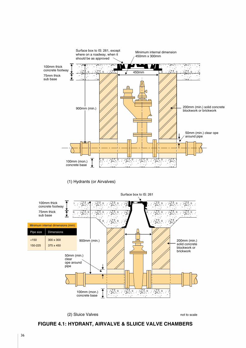
36
��������������������
@@@@@@@@@@@@@@@@@@@@
��������������������
ÀÀÀÀÀÀÀÀÀÀÀÀÀÀÀÀÀÀÀÀ
��������������������
@@@@@@@@@@@@@@@@@@@@
��������������������
ÀÀÀÀÀÀÀÀÀÀÀÀÀÀÀÀÀÀÀÀ
��������������������
@@@@@@@@@@@@@@@@@@@@
��������������������
ÀÀÀÀÀÀÀÀÀÀÀÀÀÀÀÀÀÀÀÀ
��������������������
@@@@@@@@@@@@@@@@@@@@
��������������������
ÀÀÀÀÀÀÀÀÀÀÀÀÀÀÀÀÀÀÀÀ
��������������������
@@@@@@@@@@@@@@@@@@@@
��������������������
ÀÀÀÀÀÀÀÀÀÀÀÀÀÀÀÀÀÀÀÀ
��������������������
@@@@@@@@@@@@@@@@@@@@
��������������������
ÀÀÀÀÀÀÀÀÀÀÀÀÀÀÀÀÀÀÀÀ
��������������������
@@@@@@@@@@@@@@@@@@@@
��������������������
ÀÀÀÀÀÀÀÀÀÀÀÀÀÀÀÀÀÀÀÀ
��������������������
@@@@@@@@@@@@@@@@@@@@
��������������������
ÀÀÀÀÀÀÀÀÀÀÀÀÀÀÀÀÀÀÀÀ
��������������������
@@@@@@@@@@@@@@@@@@@@
��������������������
ÀÀÀÀÀÀÀÀÀÀÀÀÀÀÀÀÀÀÀÀ
��������������������
@@@@@@@@@@@@@@@@@@@@
��������������������
ÀÀÀÀÀÀÀÀÀÀÀÀÀÀÀÀÀÀÀÀ
��������������������
@@@@@@@@@@@@@@@@@@@@
��������������������
ÀÀÀÀÀÀÀÀÀÀÀÀÀÀÀÀÀÀÀÀ
��������������������
@@@@@@@@@@@@@@@@@@@@
��������������������
ÀÀÀÀÀÀÀÀÀÀÀÀÀÀÀÀÀÀÀÀ
��������������������
@@@@@@@@@@@@@@@@@@@@
��������������������
ÀÀÀÀÀÀÀÀÀÀÀÀÀÀÀÀÀÀÀÀ
��������������������
@@@@@@@@@@@@@@@@@@@@
��������������������
ÀÀÀÀÀÀÀÀÀÀÀÀÀÀÀÀÀÀÀÀ
��������������������
@@@@@@@@@@@@@@@@@@@@
��������������������
ÀÀÀÀÀÀÀÀÀÀÀÀÀÀÀÀÀÀÀÀ
��������������������
@@@@@@@@@@@@@@@@@@@@
��������������������
ÀÀÀÀÀÀÀÀÀÀÀÀÀÀÀÀÀÀÀÀ
��������������������
��������������������
@@@@@@@@@@@@@@@@@@@@
��������������������
ÀÀÀÀÀÀÀÀÀÀÀÀÀÀÀÀÀÀÀÀ
��������������������
@@@@@@@@@@@@@@@@@@@@
��������������������
ÀÀÀÀÀÀÀÀÀÀÀÀÀÀÀÀÀÀÀÀ
��������������������
@@@@@@@@@@@@@@@@@@@@
��������������������
ÀÀÀÀÀÀÀÀÀÀÀÀÀÀÀÀÀÀÀÀ
��������������������
@@@@@@@@@@@@@@@@@@@@
��������������������
ÀÀÀÀÀÀÀÀÀÀÀÀÀÀÀÀÀÀÀÀ
��������������������
@@@@@@@@@@@@@@@@@@@@
��������������������
ÀÀÀÀÀÀÀÀÀÀÀÀÀÀÀÀÀÀÀÀ
��������������������
@@@@@@@@@@@@@@@@@@@@
��������������������
ÀÀÀÀÀÀÀÀÀÀÀÀÀÀÀÀÀÀÀÀ
��������������������
@@@@@@@@@@@@@@@@@@@@
��������������������
ÀÀÀÀÀÀÀÀÀÀÀÀÀÀÀÀÀÀÀÀ
��������������������
@@@@@@@@@@@@@@@@@@@@
��������������������
ÀÀÀÀÀÀÀÀÀÀÀÀÀÀÀÀÀÀÀÀ
��������������������
@@@@@@@@@@@@@@@@@@@@
��������������������
ÀÀÀÀÀÀÀÀÀÀÀÀÀÀÀÀÀÀÀÀ
��������������������
@@@@@@@@@@@@@@@@@@@@
��������������������
ÀÀÀÀÀÀÀÀÀÀÀÀÀÀÀÀÀÀÀÀ
��������������������
@@@@@@@@@@@@@@@@@@@@
��������������������
ÀÀÀÀÀÀÀÀÀÀÀÀÀÀÀÀÀÀÀÀ
��������������������
@@@@@@@@@@@@@@@@@@@@
��������������������
ÀÀÀÀÀÀÀÀÀÀÀÀÀÀÀÀÀÀÀÀ
��������������������
@@@@@@@@@@@@@@@@@@@@
��������������������
ÀÀÀÀÀÀÀÀÀÀÀÀÀÀÀÀÀÀÀÀ
��������������������
@@@@@@@@@@@@@@@@@@@@
��������������������
ÀÀÀÀÀÀÀÀÀÀÀÀÀÀÀÀÀÀÀÀ
��������������������
@@@@@@@@@@@@@@@@@@@@
��������������������
ÀÀÀÀÀÀÀÀÀÀÀÀÀÀÀÀÀÀÀÀ
��������������������
@@@@@@@@@@@@@@@@@@@@
��������������������
ÀÀÀÀÀÀÀÀÀÀÀÀÀÀÀÀÀÀÀÀ
��������������������
��������@@@@@@@@��������ÀÀÀÀÀÀÀÀ��������@@@@@@@@��������ÀÀÀÀÀÀÀÀ��������@@@@@@@@��������ÀÀÀÀÀÀÀÀ��������@@@@@@@@��������ÀÀÀÀÀÀÀÀ��������@@@@@@@@��������ÀÀÀÀÀÀÀÀ��������@@@@@@@@��������ÀÀÀÀÀÀÀÀ��������@@@@@@@@��������ÀÀÀÀÀÀÀÀ��������@@@@@@@@��������ÀÀÀÀÀÀÀÀ��������@@@@@@@@��������ÀÀÀÀÀÀÀÀ��������@@@@@@@@��������ÀÀÀÀÀÀÀÀ��������@@@@@@@@��������ÀÀÀÀÀÀÀÀ��������@@@@@@@@��������ÀÀÀÀÀÀÀÀ��������@@@@@@@@��������ÀÀÀÀÀÀÀÀ��������@@@@@@@@��������ÀÀÀÀÀÀÀÀ��������@@@@@@@@��������ÀÀÀÀÀÀÀÀ��������@@@@@@@@��������ÀÀÀÀÀÀÀÀ��������
������@@@@@@������ÀÀÀÀÀÀ������@@@@@@������ÀÀÀÀÀÀ������@@@@@@������ÀÀÀÀÀÀ������@@@@@@������ÀÀÀÀÀÀ������@@@@@@������ÀÀÀÀÀÀ������@@@@@@������ÀÀÀÀÀÀ������@@@@@@������ÀÀÀÀÀÀ������@@@@@@������ÀÀÀÀÀÀ������@@@@@@������ÀÀÀÀÀÀ������@@@@@@������ÀÀÀÀÀÀ������@@@@@@������ÀÀÀÀÀÀ������@@@@@@������ÀÀÀÀÀÀ������@@@@@@������ÀÀÀÀÀÀ������@@@@@@������ÀÀÀÀÀÀ������@@@@@@������ÀÀÀÀÀÀ������@@@@@@������ÀÀÀÀÀÀ������ ����
����@@@@@@@@��������ÀÀÀÀÀÀÀÀ��������@@@@@@@@��������ÀÀÀÀÀÀÀÀ��������@@@@@@@@��������ÀÀÀÀÀÀÀÀ��������@@@@@@@@��������ÀÀÀÀÀÀÀÀ��������@@@@@@@@��������ÀÀÀÀÀÀÀÀ��������@@@@@@@@��������ÀÀÀÀÀÀÀÀ��������@@@@@@@@��������ÀÀÀÀÀÀÀÀ��������@@@@@@@@��������ÀÀÀÀÀÀÀÀ��������@@@@@@@@��������ÀÀÀÀÀÀÀÀ��������@@@@@@@@��������ÀÀÀÀÀÀÀÀ��������@@@@@@@@��������ÀÀÀÀÀÀÀÀ��������@@@@@@@@��������ÀÀÀÀÀÀÀÀ��������@@@@@@@@��������ÀÀÀÀÀÀÀÀ��������@@@@@@@@��������ÀÀÀÀÀÀÀÀ��������@@@@@@@@��������ÀÀÀÀÀÀÀÀ��������@@@@@@@@��������ÀÀÀÀÀÀÀÀ��������
������@@@@@@������ÀÀÀÀÀÀ������@@@@@@������ÀÀÀÀÀÀ������@@@@@@������ÀÀÀÀÀÀ������@@@@@@������ÀÀÀÀÀÀ������@@@@@@������ÀÀÀÀÀÀ������@@@@@@������ÀÀÀÀÀÀ������@@@@@@������ÀÀÀÀÀÀ������@@@@@@������ÀÀÀÀÀÀ������@@@@@@������ÀÀÀÀÀÀ������@@@@@@������ÀÀÀÀÀÀ������@@@@@@������ÀÀÀÀÀÀ������@@@@@@������ÀÀÀÀÀÀ������@@@@@@������ÀÀÀÀÀÀ������@@@@@@������ÀÀÀÀÀÀ������@@@@@@������ÀÀÀÀÀÀ������@@@@@@������ÀÀÀÀÀÀ������
������������@@@@@@@@@@@@������������ÀÀÀÀÀÀÀÀÀÀÀÀ������������@@@@@@@@@@@@������������ÀÀÀÀÀÀÀÀÀÀÀÀ������������@@@@@@@@@@@@������������ÀÀÀÀÀÀÀÀÀÀÀÀ������������@@@@@@@@@@@@������������ÀÀÀÀÀÀÀÀÀÀÀÀ������������@@@@@@@@@@@@������������ÀÀÀÀÀÀÀÀÀÀÀÀ������������@@@@@@@@@@@@������������ÀÀÀÀÀÀÀÀÀÀÀÀ������������@@@@@@@@@@@@������������ÀÀÀÀÀÀÀÀÀÀÀÀ������������@@@@@@@@@@@@������������ÀÀÀÀÀÀÀÀÀÀÀÀ������������@@@@@@@@@@@@������������ÀÀÀÀÀÀÀÀÀÀÀÀ������������@@@@@@@@@@@@������������ÀÀÀÀÀÀÀÀÀÀÀÀ������������@@@@@@@@@@@@������������ÀÀÀÀÀÀÀÀÀÀÀÀ������������@@@@@@@@@@@@������������ÀÀÀÀÀÀÀÀÀÀÀÀ������������@@@@@@@@@@@@������������ÀÀÀÀÀÀÀÀÀÀÀÀ������������@@@@@@@@@@@@������������ÀÀÀÀÀÀÀÀÀÀÀÀ������������@@@@@@@@@@@@������������ÀÀÀÀÀÀÀÀÀÀÀÀ������������@@@@@@@@@@@@������������ÀÀÀÀÀÀÀÀÀÀÀÀ��������������@@��ÀÀ��@@��ÀÀ��@@��ÀÀ��@@��ÀÀ��@@��ÀÀ��@@��ÀÀ��@@��ÀÀ��@@��ÀÀ��@@��ÀÀ��@@��ÀÀ��@@��ÀÀ��@@��ÀÀ��@@��ÀÀ��@@��ÀÀ��@@��ÀÀ��@@��ÀÀ��
��@@��ÀÀ��@@��ÀÀ��@@��ÀÀ��@@��ÀÀ��@@��ÀÀ��@@��ÀÀ��@@��ÀÀ��@@��ÀÀ��@@��ÀÀ��@@��ÀÀ��@@��ÀÀ��@@��ÀÀ��@@��ÀÀ��@@��ÀÀ��@@��ÀÀ��@@��ÀÀ��
Surface box to IS: 261, exceptwhere on a roadway, when itshould be as approved
Minimum internal dimension450mm x 300mm
450mm
100mm thickconcrete footway
900mm (min.)
100mm (mon.)concrete base
�@�À�@�À�@�À�@�À�@�À�@�À�@�À�@�À�@�À�@�À�@�À�@�À�@�À�@�À�@�À�@�À��@�À�@�À�@�À�@�À�@�À�@�À�@�À�@�À�@�À�@�À�@�À�@�À�@�À�@�À�@�À�@�À�
100mm (mon.)concrete base
50mm (min.)clearope aroundpipe
200mm (min.)solid concreteblockwork orbrickwork
75mm thicksub base
100mm thickconcrete footway
75mm thicksub base
50mm (min.) clear opearound pipe
200mm (min.) solid concreteblockwork or brickwork
(1) Hydrants (or Airvalves)
(2) Sluice Valves not to scale
����������@@@@@@@@@@����������ÀÀÀÀÀÀÀÀÀÀ����������@@@@@@@@@@����������ÀÀÀÀÀÀÀÀÀÀ����������@@@@@@@@@@����������ÀÀÀÀÀÀÀÀÀÀ����������@@@@@@@@@@����������ÀÀÀÀÀÀÀÀÀÀ����������@@@@@@@@@@����������ÀÀÀÀÀÀÀÀÀÀ����������@@@@@@@@@@����������ÀÀÀÀÀÀÀÀÀÀ����������@@@@@@@@@@����������ÀÀÀÀÀÀÀÀÀÀ����������@@@@@@@@@@����������ÀÀÀÀÀÀÀÀÀÀ����������@@@@@@@@@@����������ÀÀÀÀÀÀÀÀÀÀ����������@@@@@@@@@@����������ÀÀÀÀÀÀÀÀÀÀ����������@@@@@@@@@@����������ÀÀÀÀÀÀÀÀÀÀ����������@@@@@@@@@@����������ÀÀÀÀÀÀÀÀÀÀ����������@@@@@@@@@@����������ÀÀÀÀÀÀÀÀÀÀ����������@@@@@@@@@@����������ÀÀÀÀÀÀÀÀÀÀ����������@@@@@@@@@@����������ÀÀÀÀÀÀÀÀÀÀ����������@@@@@@@@@@����������ÀÀÀÀÀÀÀÀÀÀ����������
900mm (min.)
Surface box to IS: 261
Minimum internal dimensions (mm)
Pipe size Dimensions
<150 300 x 300
150-225 375 x 450
FIGURE 4.1: HYDRANT, AIRVALVE & SLUICE VALVE CHAMBERS

4.16 Surface Boxes Hydrant, sluice valve, air valve and stopcock chambers should be provided with cast iron
surface boxes in compliance with the requirements of IS 261. Surface boxes for roadways
and areas accessible to wheeled traffic should be subject to approval.
Surface boxes should be bedded in mortar on the chamber walls and where the chamber is
located other than on a footway, driveway or roadway, should be surrounded by 150mm
concrete, 100mm in depth (Class E, Clause 1502, Specification for Roadworks).
4.17 Indicator Plates The location of hydrants, air valves and sluice valves should be shown by indicator plates
and Marker Posts positioned to the approval of the Local Authority.
Hydrant plates should comply with the requirements of BS 3251. They should show the
diameter of the watermain in millimetres on the upper part of the plate and the distance of
the marker from the hydrant on the lower part of the plate, as set out in Figure 4.3. All
characters should be black and the remainder of the front face should conform to colour
reference No.309 (canary yellow) of BS 381C.
Sluice valve and air valve plates should be in cast iron, measuring 200mm x 200mm. They
should have the letters SV or AV as appropriate, cast in relief. The plates should have a
background in black bitumastic paint, with the letters in white enamel.
Indicator plates may be fixed to solid boundary walls. Where marker posts are used they
should be constructed in accordance with Figure 4.3 and should be located as an inset to the
rear of the footway.
37
������
@@@@@@
������
ÀÀÀÀÀÀ
������
@@@@@@
������
ÀÀÀÀÀÀ
������
@@@@@@
������
ÀÀÀÀÀÀ
������
@@@@@@
������
ÀÀÀÀÀÀ
������
@@@@@@
������
ÀÀÀÀÀÀ
������
@@@@@@
������
ÀÀÀÀÀÀ
������
@@@@@@
������
ÀÀÀÀÀÀ
������
@@@@@@
������
ÀÀÀÀÀÀ
������
@@@@@@
������
ÀÀÀÀÀÀ
������
@@@@@@
������
ÀÀÀÀÀÀ
������
@@@@@@
������
ÀÀÀÀÀÀ
������
@@@@@@
������
ÀÀÀÀÀÀ
������
@@@@@@
������
ÀÀÀÀÀÀ
������
@@@@@@
������
ÀÀÀÀÀÀ
������
@@@@@@
������
ÀÀÀÀÀÀ
������
@@@@@@
������
ÀÀÀÀÀÀ
������
������
@@@@@@
������
ÀÀÀÀÀÀ
������
@@@@@@
������
ÀÀÀÀÀÀ
������
@@@@@@
������
ÀÀÀÀÀÀ
������
@@@@@@
������
ÀÀÀÀÀÀ
������
@@@@@@
������
ÀÀÀÀÀÀ
������
@@@@@@
������
ÀÀÀÀÀÀ
������
@@@@@@
������
ÀÀÀÀÀÀ
������
@@@@@@
������
ÀÀÀÀÀÀ
������
@@@@@@
������
ÀÀÀÀÀÀ
������
@@@@@@
������
ÀÀÀÀÀÀ
������
@@@@@@
������
ÀÀÀÀÀÀ
������
@@@@@@
������
ÀÀÀÀÀÀ
������
@@@@@@
������
ÀÀÀÀÀÀ
������
@@@@@@
������
ÀÀÀÀÀÀ
������
@@@@@@
������
ÀÀÀÀÀÀ
������
@@@@@@
������
ÀÀÀÀÀÀ
������
Surface box toIS: 261
100mm thickconcrete footway
75mm thick sub-base
600mm (min.)
Service pipe
Stopcock chamber to BS: 5834 with150mm x 65mm slotsInternal diameter 150mm
not to scale
FIGURE 4.2: STOPCOCK CHAMBER

4.18 Testing and All watermains should be hydraulically tested after laying, for a period of between 1 and 24
Sterilisation hours as approved, at a test pressure of 1.5 times the specified class pressure. The pipeline
should be adequately anchored or restrained, during the test.
A test pump, with stopcock, water tank and pressure gauge, is connected to the watermain
and operated until the gauge shows the required test pressure. (If it is considered necessary,
the calibration of the pressure gauge should be validated just prior to the test.) The amount
of water in the tank is noted at the beginning of the test period. An hour later, gauge pressure
is inspected and if it has fallen, test pressure is restored by means of the pump. This process
is repeated at hourly intervals, during the test period. The total quantity of water pumped to
maintain the pressure during the test is termed "the apparent leakage".
The apparent leakage should not normally exceed 0.11 litres, per millimetre of nominal pipe
diameter, per kilometre of length, per 24 hours.
An alternative test procedure may be approved, in consultation with the Local Authority.
Should pipelines fail this test, remedial works should be to the approval of the Local
Authority.
38
100
2
3 No. 6mm M.S. bars Diameter ofWatermain(100mm)
Distance ofmarker fromhydrant (2m)
3 No. 6mm M.S. tie-bars
25
75
230
265
240
660
450
265
TYPICAL EXAMPLE
FIGURE 4.3: CONCRETE MARKER POST

On completion of the final test, pipelines should be thoroughly flushed-out. The system
should be sterilised in sections, by allowing water containing at least 10 parts per million
residual chlorine to stand in the mains and service pipes, for at least two hours. The system
should again be thoroughly flushed-out, on completion of sterilisation.
Care should be exercised in flushing out the sterilised watermains, that the draining liquid
does not cause environmental damage.
39

5.1 Introduction Public Lighting for Housing Areas may be provided by the Electricity Supply Board (ESB), or
a private Contractor, subject to the requirements of the local authority and the ESB. Some
local authorities have adopted specific standards for Public Lighting and Developers who
intend to employ private Contractors on public lighting projects, should consult with the local
authority, before finalising the design.
5.2 Standards Public Lighting scheme equipment and installation should conform to the requirements of:
- National Rules for Electrical Installations ET 101/1991 and Amendments, published by
the Electro Technical Council of Ireland (ETCI)
- National Rules for Electrical Installations ET 102/1993, Section 714, External Lighting
Installations, published by ETCI
- National Rules for Electrical Installations, Section 533 1.1.1, with regard to Cartridge
Fuses for A.C. Circuits, published by ETCI
- IS EN 40-1: 1992, Lighting Columns, Definitions and Terms
- IS EN 55015: 1993, Limits and Methods of Measurement of Radio Disturbance
Characteristics of Electrical Lighting and Similar Equipment
- IS EN 60238: 1993, Edison Screw Lampholders
- IS EN 60598-2-3: 1994, Luminaires for Road and Street Lighting
- IS EN 60922: 1992, Ballasts for Discharge Lamps - General and Safety Requirements
- IS EN 60923: 1992, Ballasts for Discharge Lamps - Performance Requirements
- IS EN 60928: 1997, Auxiliaries for Lamps. A.C. Supplied Electronic Ballasts for Tubular
Flourescent Lamps - General and Safety Requirements
- IS EN 60929: 1993, A.C. Supplied Electronic Ballasts for Tubular Flourescent Lamps -
Performance Requirements
- IS EN 61000-3-2: 1995, Electromagnetic Compatibility (EMC). Part 3: Limits - Section
2: Limits for Harmonic Current Emissions (Equipment Input Current < 16A per Phase)
- IS EN 61048: 1993, Capacitors for Use in Tubular Fluorescent and Other Discharge
Lamp Circuits - General and Safety Requirements
40
Section 5: Public Lighting

- IS EN 61049: 1994, Capacitors for Use in Tubular Flourescent and Other Discharge
Lamp Circuits -Performance Requirements
- IS EN 61184: 1995, Bayonet Lampholders
- IS EN ISO 9001: 1994, Quality Systems - Model for Quality Assurance in Design,
Development, Production, Installation and Servicing
- IS EN ISO 9002: 1994, Quality Systems - Model for Quality Assurance in Production,
Installation and Servicing
- BS 729: 1971(1994), Specification for Hot Dipped Galvanized Coatings on Iron and Steel
Articles
- BS 1361: 1971(1986), Specification for Cartridge Fuses for A.C. Circuits in Domestic and
Similar Premises
- BS 3676: Part 1: 1989, Switches for Household and Similar Fixed Electrical Installations -
Specification for General Requirements
- BS 5489: Part 1: 1992, Road Lighting - Guide to the General Principals
- BS 5489: Part 3: 1992, Road Lighting - Code of Practice for Lighting for Subsidiary Roads
and Associated Pedestrian Areas
- BS 5649: Parts 2 to 9: 1997, Lighting Columns
- BS 6346: 1989, Specification for PVC-insulated Cables for Electricity Supply
5.3 Minimum Illuminance The minimum standard of illuminance that should be considered acceptable, can be provided
Levels by the installation of either:
- 55W SOX side-entry lanterns at 34±3m spacing, with 6m mounting height and 0.7 metre
outreach,
- 70W SONT side-entry lanterns at 34±3m spacing, with 6m mounting height and 0.7
metre outreach.
A staggered arrangement of lanterns is to be preferred for the lighting of roads with a footway
on either side, but a single side arrangement may be used, provided that the lighting criteria
are met.
41

It should be noted that the 55W SOX lanterns are more energy efficient and cost effective
than the 70W SONT alternative and are accordingly preferable whenever it is feasible to
specify them.
The recommend spacing (34 + 3m) is for a 6m roadway with a 2m footway on either side,
where vehicular traffic and public use are solely associated with adjacent properties. Should
conditions be otherwise, advice should be sought on the appropriate standard and spacing.
Other lanterns may be used, subject to approval by the ESB and the local authority.
5.4 Lighting Columns and The lighting column manufacturer should preferably be registered with and certified by the
Brackets National Standards Authority of Ireland, for the design and manufacture of lighting columns
and accessories, under their quality assurance schedule to IS EN ISO 9001 and IS EN ISO
9002.
Columns should be manufactured to BS 5649 (including any amendments), or equivalent and
also to the Department of Transport's interim design rules, which augment the requirements
of BS 5649: Part 6: 1982(1997). Lighting columns and brackets should generally be of tubular,
or octagonal steel construction, with a minimum wall thickness of 3mm and should comply
with the requirements of BS 5649: Part 3: 1982. Columns, brackets and steel fittings should
be protected against corrosion by hot-dip galvanizing, in accordance with BS 729: 1971(1994).
Mill test certificates may be required for the column and bracket steel sections.
Octagonal columns should be 7m long, of folded steel, gradually tapered at a constant rate
from the base and terminating with a dimension of 68mm across flats at the top.
Columns with a tubular cross-section should be 7m long, with a base minimum diameter of
140mm and a shaft minimum diameter of 76mm. The base length should be 3m. The junction
of the base and shaft sections should be a swaged and welded joint.
The base should be fitted with a cable entry opening, 180 x 60mm, with the top of the opening
700mm from the base end, together with a compartment door and welded-in frame. The
top of the compartment door and frame assembly should be 2700mm from the base end and
in line with the cable entry opening. The door should be weatherproof to IP 33 (IEC
classification system) and should be secured by two recessed locking mechanisms requiring a
female triangular key of 10mm side. An earthing connection should be provided within the
base compartment. The fastening screw for this connection should be of stainless steel.
The bracket assembly should be manufactured in accordance with Figure 5.1, with the bracket
arm inclined 50 above the horizontal. The bracket should be fitted with an anti-rotation
device, when fitted to a tubular column.
42

The column and bracket should carry a permanent identification mark, indicating the
manufacturer and the year of manufacture.
5.5 Lanterns Lanterns should comply with the requirements of IS EN 60598-2-3: 1994, and BS 5489: Part
3: 1992.
The lantern should be constructed from injection moulded or die-cast aluminium alloy, GRP,
or other suitable corrosion-resistant materials. The lower portion of the lantern should
consist of a single piece bowl. The earthing screw, hinges, grub screws and bowl clips or
springs should be fabricated from a corrosion-resistant material. Alternatively, the lantern
optical compartment may consist of a single piece sealed reflector/bowl unit.
The bowl should be constructed from an ultraviolet stabilised polycarbonate, which is
specially toughened, so as to be vandal resistant.
The lantern should be waterproof and dustproof by virtue of a non-porous self-sealing heat
resisting gasket where applicable and should have a minimum protection of IP65.
The lanterns should have a three-prong twist lock NEMA socket to take an approved photo-
electric control unit, suitably sealed with a weatherproof gasket and fixed to the lantern body
with non-corrosive screws.
A fixed and fused terminal block, with clearly identified phase, neutral and earth connections,
should be provided within the control gear compartment.
43
6mm VENT HOLE
WELDED STEELCOVER PLATE
3mm GUSSET
700
12560
9 No. 8mm TAPPED HOLESFITTED WITH M8 x 20 STAINLESSSTEEL SET SCREWS
88.9mm dia x 4 thk x 220 long
337mm dia x 3.2 thk
FIGURE 5.1: LIGHTING COLUMN BRACKET
5°

The lampholders on the SOX lanterns should be porcelain B.C., with stainless steel or
phosphor bronze springs and nickle-plated plungers. Lampholders on the SONT lanterns
should be of the E.S. type.
5.6 Fitting Out of A readily-detachable hardwood baseboard, measuring 400 x 80 x 20mm should be fitted
Columns in the base compartment of each column. The clearance between the baseboard and the
inside face of the door when secured, should be not less than 100mm.
Each lantern should be individually protected with a suitable fuse in the column base.
Neutral blocks, or looping-in-blocks, should be of an approved grooved bore 63A type and
should be fully insulated and solidly mounted on the baseboard.
Columns should be wired with a minimum 2.5mm2 PVC/PVC stranded copper cable.
The internal electrical arrangement should be as shown in Figure 5.2.
44
Test Switch
To Lantern
6 Amp Fuse
Neutral Block
Earth Block
Live Block
Door Frame(Lug to be crimped)
Incoming cable Outgoing cable
FIGURE 5.2: INTERNAL ELECTRICAL ARRANGEMENT PUBLIC LIGHTING COLUMN

5.7 Control Switching of the Public Lighting system should be by approved solid state photo-electric
switches, with each lantern being individually controlled. A 5A surface mounted switch,
tested to BS 3676, should be provided in the base of each column, to facilitate daytime testing
by short-circuiting the photo-electric switch.
Control gear for 55W SOX lanterns may be mounted over the lamp. In such instances, a
metal reflector should be fitted between the lamp and the control gear. Control gear for
70W SONT lanterns should not be mounted over the lamp, but should be located in a
separate compartment, sealed to a minimum of IP 43.
All lanterns should have an external ignitor in the control gear, which should be of the anti-
cycling type.
Capacitors should be rated so as to give a corrected power factor of not less than 0.9 at 230V
and should comply with the requirements of BS EN 61048: 1993 and BS EN 61049: 1993.
5.8 Auxiliary Public All columns should be supplied from an auxiliary Public Lighting micro pillar, located adjacent
Lighting Micro Pillar to the ESB section pillar. Not more than six columns may be supplied from any one circuit
and not more than four circuits may be taken from any one auxiliary Public Lighting micro
pillar.
The pillar should consist of a rectangular box of overall dimensions 600 x 150 x 150mm, with
front and rear bottom extension plates 300mm long, for anchoring purposes. The pillar
should be vented and fitted with a lift-out door, 445 x 142mm, fixed with two triangular
headed locking screws onto a suitably tapped fixing plate, with a weathering strip all around.
A key, operating both locks, should be provided with each pillar. The shell, door and
extension plates should be 3mm thick mild steel and the entire unit should be hot dipped
galvanized to BS 729. Ground level should be clearly marked on the unit.
An alternative pillar of similar design, offering additional features, may be offered for approval,
prior to installation.
5.9 Fitting Out of A hardwood baseboard, measuring 440 x 140 x 20mm should be fitted in each pillar. A main
Auxiliary Public earthing terminal should also be provided and all components should be securely mounted on
Lighting Micro Pillar the baseboard. The internal electrical arrangement should be as shown on Figure 5.3.
All outgoing circuits should be individually fused by means of a 20A HRC cut-out, capable of
accommodating cable sizes up to 25mm2. These fuses should be rated 16kA minimum
rupturing capacity and should comply with BS 1361. The terminals of the cut-out should be
of the grooved bore type.
45

Where there is more than one outgoing service cable, a main circuit fuse should also be
provided. It should be rated 30A and should otherwise be identical with the individual circuit
fuses.
The Electrical Contractor should consult with the local ESB office on ESB
interface requirements at the micro pillar.
A bituminous protective coating should be applied all around the extension plates and up to
a level on the shell extending 100mm above the ground level marking.
The installed pillar should be embedded in concrete, Class E, Clause 1502, Specification for
Roadworks.
The front of all Public Lighting micro pillars should display a high voltage warning sign (black
on a yellow face), 100mm wide by 120mm deep, securely fixed to the pillar door, as shown
in Figure 5.4.
46
FIGURE 5.3: INTERNAL ELECTRICAL ARRANGEMENT AUXILIARY MICRO PILLAR
10 Sq. mmto earth rod
10 Sq. mmto frame lug
IncomingE.S.B. Cable
OutgoingSupply Cable
Live block
20 AmpHRC Fuse
OutgoingLive Block
Neutral Block
Earth Block

5.10 Cable and Ducting All cabling should be laid underground in 100mm PVC-U ducting with a wall thickness in the
range 2.3-2.8mm. A minimum cover of 600mm to the ducting should be provided in grass
margins. A minimum cover of 750mm to the ducting should be provided at road crossings.
A spare duct should be laid across all aprons.
Two core cable with a separate earth return path should be used. Cables may be either
- 2 x 6mm2 NYCY type to VDE specification 0271/5
or
- 3 x 6mm2 PVC/SWA/PVC type to BS 6346:1989, with colours brown, blue and green-
yellow.
Cable joints are not permitted. Cables should be looped from column to column on each
circuit. If faults develop on cables prior to commissioning, the section of cable involved
should be replaced.
A duct should be provided between the ESB section pillar and the auxiliary Public Lighting
micro pillar.
5.11 Earthing All auxiliary pillars should be earthed, using an earth electrode and the supply neutralised.
The electrode should consist of a bare copper, or hot dipped galvanized steel rod/pipe of at
least 16mm diameter, driven vertically into the soil for a length of at least 1200mm. If
47
DANGER
KEEP AWAY
PUBLIC LIGHTING
FIGURE 5.4: HIGH VOLTAGE WARNING SIGN

difficulties arise in driving the vertical rod, due to underground services, a horizontal earth
electrode may be installed as follows:
A straight length of at least 4.5m of either:
- 16mm diameter bare copper,
- 16mm diameter hot dipped galvanized steel rod,
- 25mm2 cross-section bare copper,
- 25mm2 cross section hot dipped galvanized steel rod,
buried in the soil to a depth of at least 500mm. The earthing lead should exit the pillar
through the services cable entry opening.
The connection at the earth electrode should be accessible for inspection and should be
protected against corrosion by a suitable waterproof tape. The connection should be
enclosed in a galvanized steel box, with an inspection cover. After inspection, the connection
should be buried underground.
A main earth terminal should be mounted on the pillar baseboard, with the following
connections:
- 10mm2 PVC cable from the earth terminal on the pillar, with a crimped lug connection
to the pillar,
- 10mm2 PVC cable from the earth electrode,
- 10mm2 PVC cable from the neutral link.
A main earth terminal should be mounted on the baseboard fitted to each lighting column,
with the following connections:
- 6mm2 PVC cable from the earth terminal on the column, with a crimped lug connection
to the column,
- 2.5mm2 PVC cable from the lantern earth terminal.
The outer sheath of the incoming and/or outgoing service cable, should be connected to the
main earth terminal, in the case of both the lighting column and the auxiliary micro pillar
baseboards.
If PVC/SWA/PVC cables are used, the outer sheath should be terminated in an approved
manner.
48

Earth continuity cables should be coloured yellow/green, in accordance with ETCI wiring
rules. In the case of NYCY cables, appropriate yellow/green sleeving should be used.
5.12 Column Installation Lighting column bases should be treated internally and externally with a bituminous
preservative, for a distance of 1.25 metres from the end.
Where there is no grass verge, all columns should be located to the back of the footway.
The excavation for lighting columns should be a minimum of 500mm in diameter and 1.05
metres in depth.
Column erection should be in three stages as follows:
- Place 50mm of blinding concrete in the bottom of the excavation. Concrete should be
Class E, Clause 1502, Specification for Roadworks.
- Erect column vertically and centrally on the blinding and surround the column with
Grade 15.20 concrete, to a level 150mm below the service entry slot. Concrete should
be Class 30/20, Clause 1501, Specification for Roadworks. In the case of tubular
columns, an anti-rotation bar 15mm diameter should be installed.
- The final one metre of incoming and outgoing service cable up to the cable entry slot,
should be protected by polyethylene piping, which should extend 30mm into the column.
The cable should be kept level with the bottom of the entry slot, in order to avoid
damage due to column settlement.
If any other services are exposed by the excavation, care should be taken not to encase them
in the concrete surround. If necessary, an approved separating barrier should be used, in
order to maintain service access.
Excavations should be free of water when pouring the concrete surround. Columns should
be erected with the compartment door positioned on the side away from the direction of
traffic flow and should be set back a minimum distance of one metre from the kerb edge. The
installation should be completed by properly backfilling the excavation to ground level.
49

NATIONAL STANDARDS AUTHORITY OF IRELAND
IS 1: 1991 Portland Cement
IS 5: 1990 Aggregates for Concrete
IS 6: 1974 Concrete Sewer Pipes
IS 20: 1974 Concrete Building Blocks
IS 24: 1973 Test Sieves
IS 36: 1987 Bitumen Roofing Felts
IS 134: 1977 Polyethylene Pipe Type 32
IS 135: 1975 Polyethylene Pipe Type 50
IS 146: 1965 Pre-Cast Concrete Kerbs, Channels, Edgings and Quadrants
IS 261: 1984 Cast Iron Road Furniture
IS 325: 1995 Code of Practice for use of Masonry
IS 424: 1990 Unplasticized Polyvinylchloride (PVC-U) Pipes and Fittings for Buried Drainage and Sewage Systems -
Specifications
IS EN 40-1: 1992 Lighting Columns, Definitions and Terms
IS EN 124: 1994 Gully Tops and Manhole Tops for Vehicular and Pedestrian Areas
IS EN 295: 1996 Vitrified Clay Pipes and Fittings and Pipe Joints for Drains and Sewers
IS EN 512: 1995 Fibre-cement Products - Pressure Pipes and Joints
IS EN 545: 1995 Ductile Iron Pipes, Fittings, Accessories and their Joints for Water Pipelines
IS EN 1057: 1996 Copper and Copper Alloys - Seamless, Round Copper Tubes for Water and Gas in Sanitary and
Heating Applications
IS EN 10113: 1993 Hot-rolled Products in Weldable Fine Grain Structural Steels
IS EN 55015: 1993 Limits and Methods of Measurement of Radio Disturbance Characteristics of Electrical Lighting and
Similar Equipment
IS EN 60238: 1993 Edison Screw Lampholders
IS EN 60598-2-3: 1994 Luminaires for Road and Street Lighting
IS EN 60922: 1992 Ballasts for Discharge Lamps - General and Safety Requirements
IS EN 60923: 1992 Ballasts for Discharge Lamps - Performance Requirements
IS EN 60928: 1997 Auxiliaries for Lamps. A.C. Supplied Electronic Ballasts for Tubular Flourescent Lamps - General and
Safety Requirements
IS EN 60929: 1993 A.C. Supplied Electronic Ballasts for Tubular Flourescent Lamps - Performance Requirements
IS EN 61000-3-2: 1995 Electromagnetic Compatibility (EMC). Part 3: Limits - Section 2: Limits for Harmonic Current
Emissions (Equipment Input Current < 16A per Phase)
IS EN 61048: 1993 Capacitors for Use in Tubular Flourescent and Other Discharge Lamp Circuits - General and Safety
Requirements
IS EN 61049: 1994 Capacitors for Use in Tubular Flourescent and Other Discharge Lamp Circuits - Performance
Requirements
IS EN 61184: 1995 Bayonet Lampholders
IS EN ISO 9001: 1994 Quality Systems - Model for Quality Assurance in Design, Development, Production, Installation and
Servicing
IS EN ISO 9002: 1994 Quality Systems - Model for Quality Assurance in Production, Installation and Servicing
50
References

BRITISH STANDARDS INSTITUTION
BS 63: 1994 Road Aggregates
BS 65: 1991 Specification for Vitrified Clay Pipes, Fittings and Ducts, also Flexible Mechanical Joints for use solely
with Surface Water Pipes and Fittings
BS 381C: 1996 Specification for Colours for Identification, Coding and Special Purposes
BS 729: 1994 Specification for Hot Dip Galvanized Coatings on Iron and Steel Articles
BS 750: 1984 Specification for Underground Fire Hydrants and Surface Box Frames and Covers
BS 812: 1995 Testing Aggregates
BS 1010: 1973 Specification for Draw-off Taps and Stopvalves for Water Services (Screw-down pattern)
BS 1199¸ BS 1200: 1996 Specifications for Building Sands from Natural Sources
BS 1247: 1991 Manhole Steps
BS 1361: 1986 Specification for Cartridge Fuses for A.C. Circuits in Domestic and Similar Premises
BS 1377: 1990 Methods of Test for Soils for Civil Engineering Purposes
BS 2494: 1990 Specification for Elastomeric Seals for Joints in Pipework and Pipelines
BS 2499: 1993 Hot-applied Joint Sealant Systems for Concrete Pavements
BS 3251: 1993 Specification. Indicator Plates for Fire Hydrants and Emergency Water Supplies
BS 3676: 1989 Switches for Household and Similar Fixed Electrical Installations
BS 4449: 1988 Specification for Carbon Steel Bars for the Reinforcement of Concrete
BS 4483: 1985 Specification for Steel Fabric for the Reinforcement of Concrete
BS 4987: 1993 Coated Macadam for Roads and Other Paved Areas
BS 5075: 1985 Concrete Admixtures
BS 5159: 1991 Specification for Cast Iron and Carbon Steel Ball Valves for General Purposes
BS 5163: 1991 Specification for Predominantly Key-operated Cast Iron Gate Valves for Waterworks Purposes
BS 5480: 1990 Specification for Glass Reinforced Plastics (GRP) Pipes, Joints and Fittings for use for Water Supply
or Sewerage
BS 5489: 1996 Road Lighting
BS 5649: 1997 Lighting Columns
BS 5834: 1993 Surface Boxes, Guards and Underground Chambers for Gas and Waterworks Purposes
BS 5911: 1994 Precast Concrete Pipes, Fittings and Ancillary Products
BS 6346: 1989 Specification for PVC-insulated Cables for Electricity Supply
BS 6677: 1986 Clay and Calcium Silicate Pavers for Flexible Pavements
BS 6717: 1993 Precast Concrete Paving Blocks
BS 7533: 1992 Guide for Structural Design of Pavements Constructed with Clay or Concrete Block Pavers
BS 7668: 1994 Specification for Weldable Structural Steels
BS 8005: 1990 Sewerage
BS 8301: 1985 Code of Practice for Building Drainage
51

DEPARTMENT OF LOCAL GOVERNMENT
Provisional Specification for Unplasticized PVC Pipes for Cold Water Supply (1982)
DEPARTMENT OF THE ENVIRONMENT
Specification for Road Works (1995)
Surface Dressing (1981)
NATIONAL ROADS AUTHORITY
Geometric Design Guidelines (Intersections at Grade), RT 181, 1986
ELECTRO TECHNICAL COUNCIL OF IRELAND
National Rules for Electrical Installations ET 101/1991 and Amendments
National Rules for Electrical Installations ET 102/1993, Section 714, External Lighting Installations
52

53

Moltaí i dtaobh Oibreacha Forbartha Láithreáin le haghaidh Limistéir Tithíochta
AN ROINN COMHSHAOIL AGUS RIALTAIS ÁITIÚIL
DEPARTMENT OF THE ENVIRONMENTAND LOCAL GOVERNMENT
9 780707 661636
ISBN 0-7076-6163-3