Embed Size (px)
Citation preview
Recommendations on ILC Project Implementation
High Energy Accelerator Research Organization (KEK)
October 1, 2019

ii
This document summarizes the recommendations on ILC project implementation by High Energy Accelerator Research Organization (KEK). The International Linear Collider (ILC) is a next-generation experimental facility to explore fundamental laws of the Universe. The importance of electron-positron linear colliders as a future experimental facility has been long recognized by the worldwide high energy physics community. A global design team, the Global Design Efforts (GDE), was set up under the International Committee for Future Accelerators (ICFA) for design and coordination of R&D activities of the ILC in 2005, and the ILC Technical Design Report (TDR) was completed in 2013. ICFA then established the Linear Collider Collaboration (LCC) and the Linear Collider Board (LCB) and has continued to support the worldwide efforts for realizing the ILC. Meanwhile, in 2012, KEK and the high energy physics community in Japan proposed that Japan should host the ILC, which was welcomed by the worldwide high energy physics community. Implementation of the ILC project will require strong involvements from international partners due to its scientific importance and large scale. Aspects of international cost sharing and governance of the organization carrying out the ILC project will need to be discussed and agreed at the governmental level. Therefore, KEK established an International Working Group (WG) on the ILC Project in May 2019, inviting scientific experts worldwide*, and asking them to study international aspects of the project implementation from viewpoints of researchers. They were requested to create a report on model of international cost sharing for construction and operation, organization and governance of the ILC Laboratory, and international sharing of the remaining technical preparation. The WG report was submitted to KEK on September 25, 2019. After reviewing the content of the report, KEK decided to make it available within this document entitled “Recommendations on ILC Project Implementation”. This document summarizes the deliberations from researchers’ viewpoints; it does not intend to pre-empt governments and funding agencies. It is hoped that it will be helpful for discussions among governments and funding agencies. Finally, KEK wishes to thank the Working Group members for submitting the report in a timely manner. * The WG members are listed in the Appendix B of the WG report.

iii
iv
Report of KEK International Working Group on the ILC Project
KEK International Working Group on the ILC Project
September 25, 2019

i
TABLE OF CONTENTS
1. Introduction ..................................................................................................................... 1
2. International Cost Sharing for ILC Construction and Operation .................................. 3
2.1. General Principles......................................................................................................... 3 2.2. Sharing of ILC Construction Cost .................................................................................. 4 2.2.1. Civil Engineering ...................................................................................................... 4 2.2.2. Conventional Facilities.............................................................................................. 4 2.2.3. Superconducting RF and Accelerator Components .................................................. 5 2.2.4. Sharing of Person-Power Contributions during Construction of the Accelerator ........ 5 2.2.5. ILC Laboratory Central Budget During Accelerator Construction .............................. 6 2.3. Sharing of ILC Detector Construction and Operation .................................................... 7 2.4. Function of the ILC International City ............................................................................ 7 2.5. Sharing of Operational Cost .......................................................................................... 8 2.6. Sharing of the Decommissioning Cost .......................................................................... 8
3. Organization and Governance ........................................................................................ 9
3.1. Introduction ................................................................................................................... 9 3.2. ILC Pre-Lab ................................................................................................................ 10 3.2.1. Host Laboratory and Member Laboratories ............................................................ 10 3.2.2. Mandate ................................................................................................................. 10 3.2.3. Organization ........................................................................................................... 11 3.2.4. Funding .................................................................................................................. 11 3.2.5. Project Management .............................................................................................. 12 3.2.6. Preparation for Mass Production and Towards Hub Laboratories ........................... 12 3.2.7. Regional Design Offices ......................................................................................... 12 3.2.8. Interplay between the Pre-Lab and Inter-governmental Negotiations...................... 13 3.3. ILC Laboratory ............................................................................................................ 13 3.3.1. Legal Basis............................................................................................................. 13 3.3.2. Governance and Organizational Structure .............................................................. 14 3.3.3. Council Representation and Voting Structure ......................................................... 14 3.3.4. Laboratory and Project Management...................................................................... 15 3.3.5. Interface between ILC Laboratory and Experiments ............................................... 16
4. Technical Preparation Plan in Response to MEXT’s ILC Advisory Panel and the Science Council of Japan (SCJ) ................................................................................... 17
4.1. Technical Preparation Plan of the Main Preparatory Phase......................................... 17 4.2. Specific Items Identified by MEXT’s ILC Advisory Panel and the SCJ report ............... 18
5. Summary ........................................................................................................................ 23
Appendices ........................................................................................................................ 24
A. Charge to KEK International Working Group on the ILC Project ............................... 24
B. Member List of KEK International Working Group on the ILC Project....................... 25
C. Member List of the Preparatory Group ........................................................................ 25
D. Meeting Records ........................................................................................................... 25
ii
E. Current Status of ILC Accelerator ................................................................................ 26
E.1. ILC250 Accelerator Overview ...................................................................................... 26 E.2. ILC Accelerator Preparation Status ............................................................................. 26 E.2.1. Superconducting RF (SCRF) cavities ..................................................................... 26 E.2.2. Positron Source ...................................................................................................... 27 E.2.3. Damping Ring ........................................................................................................ 29 E.2.4. Interaction Region .................................................................................................. 29 E.2.5. Beam Dump ........................................................................................................... 30
1
1. Introduction The International Linear Collider (ILC) is a next-generation experimental facility to explore fundamental laws of the Universe being proposed by the international community of high energy physics. Electron and positron beams will be accelerated from opposite ends of a linear tunnel of 20 km and focused to collide with a center-of-mass energy of 250 GeV in the current baseline design. The ILC will be a Higgs factory, which will produce and precisely measure a large number of Higgs boson particles, and will provide an ideal opportunity to search for new physics. The facility can be extended to higher collision energy at a later stage. The international high energy physics community has been promoting electron-positron linear colliders as a future large accelerator facility for more than two decades. Due to the strong international interest and its large size, the ILC is conceived by the community as an international project. The International Committee of Future Accelerators (ICFA) established the Global Design Effort (GDE) for design and coordination of R&D activities of the ILC in 2005. The GDE completed the ILC Technical Design Report (TDR) in 2013. ICFA has continued to support the worldwide effort to realize a linear collider by establishing the Linear Collider Collaboration (LCC) as well as the Linear Collider Board (LCB), a supervising body for linear collider activities. After the discovery of the Higgs boson at the LHC in the summer of 2012, KEK and the high energy physics community in Japan proposed1 in October 2012 that Japan host the ILC. This proposal was welcomed by the high energy physics community worldwide, for instance in the European Strategy for Particle Physics update (2013), the US P5 Report (2014), and several statements by ICFA and the Asian Committee of Future Accelerators (ACFA). In May 2013, the Ministry of Education, Culture, Sports, Science and Technology (MEXT) asked the Science Council of Japan (SCJ) to study the ILC project from a scientific viewpoint. In September 2013, the SCJ produced a “Report on the International Linear Collider Project”2 and recommended MEXT to investigate various issues to determine the possibility of hosting the ILC. In May 2014, MEXT established the ILC Advisory Panel and started to study issues pointed out by the SCJ. Meanwhile, in light of LHC early Run 2 results, the high energy physics community in Japan proposed3 “to construct a 250 GeV center-of-mass ILC promptly as a Higgs factory.” This proposal was carefully studied by LCB/LCC and endorsed by ICFA in November 2017. A report was released by MEXT’s ILC Advisory Panel4 in July 2018, and in reply to the request of MEXT, the SCJ submitted the “Assessment of the Revised Plan of the International Linear Collider Project”5 to MEXT in December 2018. MEXT then presented its view in regard to the ILC project at the LCB meeting6 on March 7, 2019 in Tokyo. Although “MEXT has not yet reached declaration for hosting the ILC in Japan at this moment”, “MEXT will continue to 1 http://www.jahep.org/office/doc/201210_ILC_staging_e.pdf 2 http://www.scj.go.jp/ja/info/kohyo/pdf/Report_on_ILC_Exective_Summary.pdf 3 http://www.jahep.org/files/JAHEP-ILCstatement-170816-EN.pdf 4 http://www.mext.go.jp/component/b_menu/shingi/toushin/__icsFiles/afieldfile/2018/09/20/1409220_2_1.pdf 5 http://www.scj.go.jp/ja/info/kohyo/pdf/kohyo-24-k273-en.pdf 6 https://www.kek.jp/en/newsroom/2019/03/13/2100/
2
discuss the ILC project with other governments while having an interest in the ILC project.” At the same meeting, MEXT said it hoped that KEK will set up a working group with international participation in order that discussions within the community of domestic and international researchers would proceed on topics such as international cost sharing. KEK accordingly established an International Working Group on the ILC Project in May 2019. This group was to also address the issues raised by SCJ. Members of the Working Group were appointed by the Director-General of KEK. The Working Group consists of seven members, two from Europe, two from North America, and three from Asia including two from Japan. The members were invited by KEK as scientific experts in the fields related to the ILC project; they do not formally represent the community of researchers or the organizations with which the members are affiliated. The Working Group (WG) was charged to submit a report to the Director-General of KEK on the following broad points7: l Model of international cost-sharing for construction and operation
Ø Study the construction cost of the 250 GeV version of the ILC (ILC250) based on the ILC-TDR cost estimate, and propose a model for the construction describing: (a) items that are appropriate for the host responsibility, and (b) items that should be shared by all partners. In addition, propose a model for sharing the operational and decommissioning costs.
l Organization and governance of the ILC Laboratory Ø Propose an organizational and governance model for the ILC Laboratory as well as
the ILC Pre-Lab. l International sharing of the remaining technical preparation
Ø Present a technical preparation plan for the preparatory phase to solve the technical issues pointed out in MEXT’s ILC Advisory Panel report and the SCJ report, including the possibility of international cooperation.
Many of these issues were already studied by the GDE and LCB/LCC. Originally, there was a supplemental document to the ILC-TDR called “ILC Project Implementation Planning” (ILC-PIP). The document was updated in 2015 assuming the candidate site of the ILC is in Japan. The WG has used the Revised ILC-PIP (July 2015, Revision C)8 as a starting point of its discussion. A preparatory group was formed to help preparing materials for discussions and writing the report.9 The WG had five meetings between May 2019 and September 2019.10 A draft report was presented at the LCB meeting on August 7, 2019 for comments and feedback. This document summarizes the conclusions of the Working Group. The purpose of this document is to present some important aspects on implementation of the ILC project, so that KEK can utilize the suggestions therein to prepare a report for MEXT as an input for discussions at the governmental level. It is hoped that this document will be helpful for discussions among governments and funding authorities; it does not intend to pre-empt any necessary discussions among governments and funding authorities.
7 Full text of the charge is shown in Appendix A; the WG members are listed in Appendix B. 8 http://ilcdoc.linearcollider.org/record/62116/files/PIP_complete_IssueC.pdf 9 The preparatory group members are listed in Appendix C. 10 Meeting records can be found in Appendix D.
3
2. International Cost Sharing for ILC Construction and Operation 2.1. General Principles The establishment of the ILC as an international project (“ILC project”) implies that ILC construction, operation and decommissioning costs should be shared internationally. Intergovernmental negotiations should forge a joint inter-governmental agreement on cost sharing of the ILC project and how the project will be collaboratively realized. The agreement will generally be preceded by the necessary procedures within each state that will contribute to the ILC project, such as discussions by science council bodies and project approvals by funding agencies. It is envisaged that the Member States of the ILC project consist of a Host State, where the ILC accelerator will be sited, and non-host Member States, which contribute to the project in its construction, operation, and decommissioning. The Host State as well as the non-host Member States are the stakeholders of the ILC project; all stakeholders should be committed beyond their deliverables to the success of the overall project. The ILC Laboratory is defined as an international laboratory consisting of all the facilities in the accelerator site, the central campus, and the related facilities located in the same region. It is expected that significant work for ILC construction will be done outside the ILC Laboratory. The deliverables of that work constitute in-kind contributions to the ILC project. It is foreseen that sharing of the cost of ILC construction will be via a combination of in-kind, monetary, and labor contributions. The level of contribution of each Member State, as well as its admixture of in-kind, monetary, and labor contributions, should be driven by the Member State’s interests, technical capabilities, and the resource requirements of the project. Member States will be naturally motivated to make in-kind contributions because of the scientific, technological, and economic benefits that will accrue from producing accelerator components within their states. Member States should also be motivated to make monetary and labor contributions in order to further the project and its scientific program as a whole by sharing necessary ILC costs that are not amenable to in-kind contribution. Monetary contributions will be used to fund the ILC Laboratory’s central budget (See Section 2.2.5). Labor contributions are discussed in Section 2.2.4. The in-kind, monetary, and labor contributions of all Member States should be determined via international discussion and negotiation. In this document, an in-kind contribution is defined as a contribution of manufactured components. The contributing Member State takes primary responsibility for the function, performance, and maintenance of the delivered components throughout the life of the ILC project. In-kind contributions must be produced according to engineering and manufacturing specifications defined by the ILC project. For accounting purposes, the value for the construction of each in-kind contribution will be based upon the project’s estimate of the cost of the corresponding component or system at the time of the joint inter-governmental agreement. In this document, “standard sharing” is defined by the set of agreed fractional contributions of all Member States, where the fractional contribution of each Member State is calculated from the sum of all its in-kind, monetary, and labor contributions to ILC construction, divided by the total construction cost. The sum over different types of contributions should use agreed
4
conversion factors between types. The calculation does not include the cost of detector construction and operation. Standard sharing is sharing according to these agreed fractions, specified in the joint inter-governmental agreement. Sharing of operational cost and of decommissioning cost are discussed in Sections 2.5 and 2.6. 2.2. Sharing of ILC Construction Cost The following breakdown of the cost for ILC accelerator complex is considered in this section.
- Civil engineering (approx. 22%) including tunnels and surface buildings
- Conventional facilities (approx. 15%) including AC power (electrical transformers, cables, distribution), water cooling (pipes/pumps), water supply/drainage, air-conditioning, networking, handling, safety, and alignment.
- Superconducting RF (approx. 35%) including cavities, cryomodules, and RF power sources (Klystrons/modulators).
- Accelerator components (approx. 28%) including magnets, power supplies, vacuum systems, beam dumps, instrumentation, controls, and cryoplants.
The fractions in parentheses correspond to the approximate fractions relative to the full cost of ILC250 construction 11 (“ILC250 cost estimate”). Labor for the civil engineering and construction of the conventional facilities is included in these fractions, as in the TDR. The cost of labor from the ILC Laboratory and contributing laboratories in Member States is not included in these fractions because labor costs vary by Member State. The details of the labor are discussed in Section 2.2.4. The cost of infrastructure and services outside the ILC Laboratory, discussed in Section 2.4, is not included. 2.2.1. Civil Engineering It is foreseen that the civil engineering will be provided by the Host State as an in-kind contribution, with the reasoning that the tunnels and buildings cannot be moved and, after the end of the ILC operation, will naturally become an asset of the Host State. The land needed for the ILC site is to be acquired and provided by the Host State, as is the regional transportation infrastructure to support construction and operation of the ILC. The cost of land acquisition and regional infrastructure is not included in the project cost or as an in-kind contribution in the context of this document. 2.2.2. Conventional Facilities The conventional facilities provide the critical utilities for ILC construction and operation. The main cost drivers of the construction of conventional facilities are AC power (approx. 40%) and water facilities (approx. 35%), with air-conditioning, networking, handling equipment, safety, and alignment and survey being the other important components. Construction of conventional
11 The numbers are obtained from input documents to MEXT’s Advisory Panel and SCJ’s ILC evaluation committee; p.38, http://www.mext.go.jp/component/b_menu/shingi/toushin/__icsFiles/afieldfile/2018/09/20/1409220_2_1.pdf
5
facilities is closely interconnected with the civil engineering. Planning and construction are site-specific, including considerations concerning local regulations and local utility suppliers. For these reasons, it is natural that the Host State will provide a significant part of the conventional facilities as in-kind contributions. Nevertheless, the ILC Laboratory may accept in-kind contributions to conventional facilities from non-host Member States. Possible examples are electrical transformers and water pumps. Since the failure of conventional facilities tends to cause more critical effects than failures of other accelerator components, the ILC Laboratory should have full control of the facilities for quicker reaction. Therefore, the procedure of the operation and maintenance of the in-kind components of the facilities may be different from the basis of the in-kind contributions written in Section 2.1. 2.2.3. Superconducting RF and Accelerator Components Superconducting RF and accelerator components will comprise the main part of international cost sharing, which will be mostly carried out via in-kind contributions. Approximately 9,000 superconducting RF cavities need to be produced, which are used for manufacturing approximately 900 RF cryomodules, corresponding to about 25-30% of the total ILC construction cost. It is to be noted that these numbers are about a factor of ten larger than the numbers in any existing large-scale accelerator projects. It is assumed that several regional hub laboratories will be set up, each to produce large numbers of cryomodules for the ILC. Cryomodules will be assembled in each hub laboratory and transported to the ILC Laboratory, where their performance will be checked before installation in the ILC tunnel. In-kind contribution of other accelerator components can be contributed from a wider pool of Member States and laboratories than for superconducting RF, matching the technical complexity and cost to the expertise and resources of potential contributors. Contribution of complete functional subsystems is preferable to components. The ILC Laboratory should provide facilities for maintenance and testing of in-kind components from all Member States. 2.2.4. Sharing of Person-Power Contributions during Construction of the Accelerator The person-power at the ILC Laboratory and contributing laboratories worldwide is categorized along with its estimated fraction as:
(a) assembly, test, and integration of accelerator components (approx. 50%), (b) management of civil engineering and conventional facilities (approx. 5%), (c) directorate, project management, and administration (approx. 20%), (d) installation of the ILC accelerator components on site (approx. 25%).
The person-power required for assembly, test, and integration of accelerator components (a) has two portions, a portion provided by Member States and a portion directly employed at the ILC Laboratory. It is understood that the Member States should provide person-power for assembly and test of in-kind accelerator components in the laboratories of the contributing

6
Member States (e.g. the hub laboratories), for transportation to the ILC Laboratory, and for integration at the ILC Laboratory. This person-power is considered as a labor contribution by the Member State responsible for each in-kind contribution. Employment contracts should generally be made by the Member States. The ILC Laboratory can also employ persons working at the ILC Laboratory with budget contributed from the responsible Member State, if necessary. This person-power at the ILC Laboratory should also be counted as labor contributions by the Member States providing the funding. A significant fraction of staff is expected to work on long-term assignment to the ILC Laboratory from member state laboratories and is counted as labor contributions. Nonetheless, it is desirable for some of the person-power for integration as well as for coordination at the ILC Laboratory to be directly employed by the ILC Laboratory. The directly-employed staff comprises the second portion of category (a). A strong scientific and technical staff directly employed by the ILC Laboratory is desired if sufficient funding via the central budget can be secured from contributions by the Member States. The international negotiations should discuss what proportions of the necessary scientific and technical staff resident at the ILC Laboratory should be provided by long-term assignments from Member States and by direct employment by the ILC Laboratory. Person-power to manage civil engineering and construction of conventional facilities (b), because of its close connection to local industry, is expected to be fully provided by the Host State as a labor contribution. The Directorate (discussed in Section 3) should be employed by the ILC Laboratory and paid from the central budget, to ensure the independence of management from national interests. The project management team and most of administrative staff working at the ILC Laboratory are foreseen to be employees of the ILC Laboratory and funded by the central budget. Person-power for installation at the ILC Laboratory of in-kind accelerator contributions (d) is separated into two parts. The necessary expertise to ensure the quality of components contributed in kind should be provided as a labor contribution by the Member States engaged in the in-kind contribution. Non-expert person-power required for installation can mainly come from the Host State with contracts under the ILC Laboratory, while keeping the possibility of labor contributions from non-host Member States. 2.2.5. ILC Laboratory Central Budget During Accelerator Construction The central budget of the ILC Laboratory will be crucial for timely completion of ILC construction. The central budget is intended for the following three categories of expenditure:
(A) salaries of person-power directly employed by the ILC Laboratory excluding installation, (B) salaries for installation person-power, and (C) central contingency.
For categories (A) and (C), standard sharing, as defined in Section 2.1, should be applied. For category (B), the contribution from the Host State is expected to be larger than that in standard sharing, considering that most of the person-power is expected to come from the Host State.

7
The budget for categories (A) and (B) is used for employing person-power described in Section 2.2.4 (c) and part of person-power described in Section 2.2.4 (a) and (d). It is included in the ILC250 cost estimate. The central contingency (C) discussed here is the budget to deal with unforeseen cost increases of activities covered by the central budget, or increases caused by issues for which the project management team is responsible (e.g. design changes of interfaces). This central contingency should not be used for cost overrun of in-kind contributions, although in exceptional cases the ILC Laboratory can use central contingency funds to keep ILC construction on track. Experience from past projects shows that contingency is critically important. The appropriate size of the central contingency budget should be determined at the time of the inter-governmental agreement. A figure of about 10% of the total project cost could be used until then. Any surplus of the central contingency budget after completion of ILC construction should either be returned to Member States in proportion to their contributions or transferred to the central contingency budget for the operation phase. The central contingency is not included in the ILC250 cost estimate. 2.3. Sharing of ILC Detector Construction and Operation The funding of detector construction and operation of high-energy physics experiments is traditionally separate from the funding of accelerator construction. Detector collaborations are expected to pay for the cost of the detector. The method of international sharing of detector costs should be discussed and agreed upon within the detector collaboration, and the method may be different for the construction and operation phases. For the construction phase, the level of contribution of each participating partner is driven by the partner’s interests, technical capability, and resources. During the operation phase, when scientific results are being published, past experience shows that sharing could be related to the number of Ph.D. researchers participating in the collaboration. Although the ILC Laboratory is responsible for the success of the experimental program, it is not foreseen that it will take a major role in the construction of detector components. The Laboratory should provide the experimental areas and all the services related to the experimental areas including utilities and ventilation. The Laboratory should also provide infrastructure and services, as well as necessary support for assembly and installation, including clean room facilities for sensitive detectors (e.g. silicon detectors). The boundaries between the responsibilities of the ILC Laboratory and detector collaborations should be clearly defined in the ILC Laboratory cost estimate. 2.4. Function of the ILC International City For attracting an international community, the Host State and local government are expected to provide a living environment around the ILC Campus that is friendly and welcoming to the international community, such as sufficient and affordable residences for long- and short-term stay, language support in everyday life, educational and medical aspects, and facilitation of locating job opportunities for family members for attracting international community. The cost
8
of the preparation and operation of these items is not included in the project cost. 2.5. Sharing of Operational Cost The ILC operational cost includes:
(a) the necessary utilities such as electricity and water, (b) the person-power for accelerator operation, (c) the person-power for management and administration and the necessary operational cost of the ILC Laboratory, and (d) the cost of maintenance and repair of the accelerator.
Operational costs should be shared among Member States including the Host State. The way in which the operational cost will be shared should be agreed upon before construction. It could be related to the capital contributions to construction. Among several ways to share the operational cost are via:
(A) contribution of maintenance of in-kind components, (B) contribution of labor for operation and management, and (C) cash contribution.
In-kind contributions (A) and labor contributions (B) should be encouraged in order to minimize the need for cash contributions. However, some level of cash contribution will be necessary, particularly because a significant fraction of the operational cost is for utilities. 2.6. Sharing of the Decommissioning Cost The ILC Laboratory and Member States should be responsible for the decommissioning of the ILC after the end of its operation. Decommissioning here refers to the dismantling of the ILC accelerator and does not include long-distance shipping of the components. It is estimated that the full cost of decommissioning, including that of in-kind contributions, amounts to about two years of the operational cost. A possible model for funding the decommissioning is to extend the operational cost by approximately two additional years. The decommissioning of components provided by in-kind contributions should be primarily undertaken by the contributors themselves; it is often the case that the provided components retain values at the end of the project and are reused for other purposes. In this model, it is suggested that the Member States contribute the difference between the extended operational cost and the decommissioning cost of in-kind components towards the central laboratory’s decommissioning cost for the remaining components. Agreement on such arrangements should be made before the construction.
9
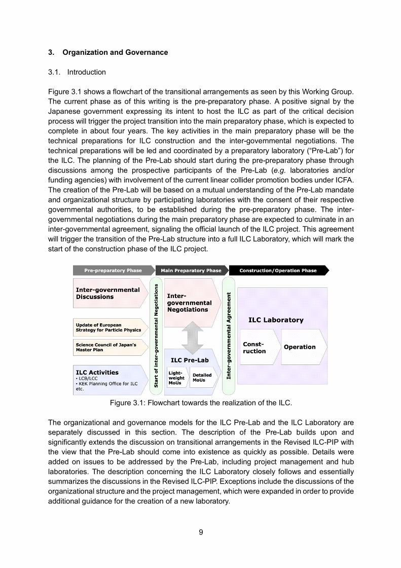
3. Organization and Governance 3.1. Introduction Figure 3.1 shows a flowchart of the transitional arrangements as seen by this Working Group. The current phase as of this writing is the pre-preparatory phase. A positive signal by the Japanese government expressing its intent to host the ILC as part of the critical decision process will trigger the project transition into the main preparatory phase, which is expected to complete in about four years. The key activities in the main preparatory phase will be the technical preparations for ILC construction and the inter-governmental negotiations. The technical preparations will be led and coordinated by a preparatory laboratory (“Pre-Lab”) for the ILC. The planning of the Pre-Lab should start during the pre-preparatory phase through discussions among the prospective participants of the Pre-Lab (e.g. laboratories and/or funding agencies) with involvement of the current linear collider promotion bodies under ICFA. The creation of the Pre-Lab will be based on a mutual understanding of the Pre-Lab mandate and organizational structure by participating laboratories with the consent of their respective governmental authorities, to be established during the pre-preparatory phase. The inter-governmental negotiations during the main preparatory phase are expected to culminate in an inter-governmental agreement, signaling the official launch of the ILC project. This agreement will trigger the transition of the Pre-Lab structure into a full ILC Laboratory, which will mark the start of the construction phase of the ILC project.
Figure 3.1: Flowchart towards the realization of the ILC.
The organizational and governance models for the ILC Pre-Lab and the ILC Laboratory are separately discussed in this section. The description of the Pre-Lab builds upon and significantly extends the discussion on transitional arrangements in the Revised ILC-PIP with the view that the Pre-Lab should come into existence as quickly as possible. Details were added on issues to be addressed by the Pre-Lab, including project management and hub laboratories. The description concerning the ILC Laboratory closely follows and essentially summarizes the discussions in the Revised ILC-PIP. Exceptions include the discussions of the organizational structure and the project management, which were expanded in order to provide additional guidance for the creation of a new laboratory.

10
3.2. ILC Pre-Lab 3.2.1. Host Laboratory and Member Laboratories The Pre-Lab is based on a partnership among laboratories for preparation of ILC accelerator construction. The Pre-Lab should be hosted by KEK (“host laboratory”) as it is the de facto national laboratory for high energy physics in Japan. The laboratories that form the Pre-Lab including the host laboratory are the “member laboratories”. The “participating partners” for the Pre-Lab refer to either the member laboratories themselves or their funding agencies, whichever is appropriate in the context being used, as the organizational structure is different for the different laboratories and different countries or regions. The relation between the Pre-Lab and its member laboratories is as follows. The technical preparation work for the ILC is to be shared and carried out by the member laboratories. The Pre-Lab plays a leading role in the coordination of such efforts. The Pre-Lab activities that are specific to the Host State, such as those requiring field work at the ILC accelerator site, will be led by the host laboratory. As the host laboratory, KEK is expected to provide office space for the personnel directly employed by the Pre-Lab. To facilitate its establishment, a two-stage MoU approach is proposed as the basis for the Pre-Lab. The first-stage agreements will be lightweight MoUs signed between KEK and participating partners. The lightweight MoUs should contain an expression of interest to participate in the main preparatory phase of the ILC and the Pre-Lab. Once funding has been assured to a participating partner, a second-stage agreement, in the form of a detailed MoU, should be signed between KEK and this partner. These detailed MoUs should include a commitment of budget and an agreement on the specific tasks and schedule to be undertaken by the member laboratory. The membership of the Pre-Lab should be dynamic and ready to grow. New members are to be added as they become ready and sign MoUs. 3.2.2. Mandate The mandate of the Pre-Lab is to coordinate international efforts in the main preparatory phase towards the construction of the ILC and to provide necessary information to assist the inter-governmental negotiations. The interplay between the Pre-Lab and inter-governmental negotiations is described in Sec. 3.2.8. The remaining necessary technical preparations are to be shared and carried out by the member laboratories. Preparation for mass production of the ILC accelerator components should begin at this stage. The engineering design, including the environmental impact assessment and civil engineering tasks such as geological survey, should be carried out and reviewed periodically by setting up a machine advisory committee. The engineering design should resolve open issues of the ILC configuration, including consideration of risk and cost. Among the open issues are the SCRF cavity specifications following performance R&D, and the positron source layout. At the same time, the requirements and timelines relevant to the machine-detector interface should be reviewed in consultation with the worldwide high-energy physics community. Preparations for the experimental program at the ILC Laboratory should be initiated and technical development of detector concepts should be fostered. A schedule should be proposed for the readiness towards a full ILC Laboratory. At the end of its mandate,

11
the Pre-Lab is expected to transition into the ILC Laboratory, provided that there is final approval of the ILC project based on an inter-governmental agreement. The Pre-Lab should also play a leading role in outreach and communication of the merits of the ILC project to the general public. 3.2.3. Organization The elements of the Pre-Lab organization should be a Governance Board, a Director, a Directorate, and the member laboratories. The Governance Board is the ultimate decision-making authority. Its membership is composed of representatives of the participating partners. A minimum level of contribution to accelerator design may be established for a participating partner to be represented in the Governance Board. The representatives should be of high enough standing that they are able to make timely decisions concerning Pre-Lab activities. The Governance Board should delegate the management of Pre-Lab activities to the Director. The Director, assisted by the Directorate, manages the Pre-Lab activities. The Director should have significant delegated authority from the Governance Board necessary for decisive action without continual referral to the Governance Board. The Director is appointed by the Governance Board after a search by a selection committee set up by the Governance Board. During the initial stage of the Pre-Lab, while the selection process is ongoing, an Interim Director should be appointed by the host laboratory. The Director reports to the Governance Board. The Directorate is composed of associate directors each responsible for a major area of Pre-Lab activity, such as project management, accelerator design, environmental impact assessment and civil engineering, and physics and detector coordination. Members of the Directorate are nominated by the Director and approved by the Governance Board. The Directorate reports to the Director. The member laboratories, under the direction of the Director and Directorate, collectively execute the Pre-Lab activities, according to the plans detailed in the MoUs. The member laboratories or their funding agencies are represented in the Governance Board. Appropriate external committees advisory to the Governance Board should be established, as should appropriate external committees advisory to the Director. 3.2.4. Funding The funding for Pre-Lab activities can be categorized as follows: (a) central budget for the Pre-Lab; (b) budget available to individual member laboratories for Pre-Lab activities; (c) budget allocated by the Host State for site-specific preparations. (a) The central budget for the Pre-Lab will be needed to pay the salaries of the top
management, the administrative staff, and a minimal number of project management experts from outside the scientific community. Initially, this central budget is expected to

12
be seeded by the Host State as part of the preparatory budget. Sharing of the central budget may be negotiated at a later stage as budgetary commitment becomes possible.
(b) Member laboratories are expected to provide funding for completing the technical
preparations and engineering design for which they will be responsible. The division of tasks and expected schedule should be outlined in the detailed Pre-Lab MoUs.
(c) Funding for tasks that are closely tied to the accelerator site, such as environmental impact
assessment and civil engineering, is expected to come from the Host State as part of the preparatory budget.
3.2.5. Project Management A dedicated project management team will be critical for the successful construction of the ILC. This project management effort should start early during the main preparatory phase. In addition to supporting the activities of the remaining necessary technical preparations and engineering design, the Pre-Lab project management team should define the project management procedures and tools for the construction phase. The project management team should incorporate expertise from outside the scientific community, including both the public and private sectors. 3.2.6. Preparation for Mass Production and Towards Hub Laboratories The preparatory work towards mass production of the accelerator components is expected to begin during the main preparatory phase. Member laboratories who have, or will have, the capabilities and the expertise for producing large quantities of accelerator components, such as SCRF cavities,12 cryomodules, and related components, are to start coordinating the personnel and facilities needed for mass production. These production centers are expected to be the precursors to the hub laboratories during the construction phase. The actual implementation of full-scale hub laboratories will come after the final agreement on the ILC project. 3.2.7. Regional Design Offices A regional design office is an optional organization during the main preparatory phase that plays a central coordinating role in combining regional efforts towards the preparation and the construction of the ILC.13 Regional design offices can coordinate some of the regional bidding and contracts as well as centralize the regional efforts for the engineering design. Setting up this organization will depend on how funding will be made available as a regional effort. Regional design offices could be precursors to regional project offices during the construction phase.
12 The technical preparation plan includes the manufacturing of a significant number of cavities and cryomodules; see Section 4.2. 13 Horizon 2020 / E-JADE Report (2018). The European ILC Preparation Plan. https://www.e-jade.eu/sites/sites_custom/site_e-jade/content/e49893/e65922/e73204/ILC-EIPP.E-JADE.v2.12.20180703.pdf
13
3.2.8. Interplay between the Pre-Lab and Inter-governmental Negotiations The success of the inter-governmental agreement critically depends on the close interaction of the prospective Member States with the laboratories participating in the Pre-Lab. The Director of the Pre-Lab should play a leading role in facilitating the inter-governmental negotiations and in providing all necessary information. The interplay between the Pre-Lab and inter-governmental negotiations is expected to be bi-directional. The Pre-Lab will assist the inter-governmental negotiations by providing technical information. At the same time, certain technical decisions in the Pre-Lab activities may require guidance from the inter-governmental negotiations; these include decisions on the open issues related to the engineering design, as discussed in Sec. 3.2.2. Various topics requiring technical input are expected to be raised during the inter-governmental negotiations, such as, but not limited to, costing, organization, and project management. It is recommended to form an appropriate organizational structure within the Pre-Lab in order to address these topics. This could be achieved, for example, by forming a dedicated working group on each of these topics. The planning for the topics to be addressed by the Pre-Lab should begin as soon as possible in the pre-preparatory phase. The Director of the Pre-Lab should be the official point of contact connecting the Pre-Lab and the inter-governmental negotiations. The proposed working groups should report to the Director. The Director will be responsible for communicating the findings and conclusions of the Pre-Lab as technical input to the inter-governmental negotiations. 3.3. ILC Laboratory 3.3.1. Legal Basis The concept of the ILC Laboratory being established as an international laboratory supported by Host as well as non-host Member States is introduced in Section 2.1. It will be preferable to set up the ILC Laboratory as an international treaty organization; however, if there are constraints by some Member States that will make it difficult to come to a treaty agreement, possibilities should be explored for an alternative form of inter-governmental agreement. In either case, the following aspects are recommended to be considered for the inter-governmental agreement for the ILC Laboratory. - Stability of the project, including long-term budgetary commitment by Member States. - Rights and obligations of the Host State and non-host Member States. - Exemption of import duties and taxes. - Managing of intellectual property. - Labor standard of the Host State. - Rules of financial management, including the possibility of bank loans.14 - Decommissioning procedures and responsibilities.
14 For example, CERN was able to take out bank loans which helped manage its LHC construction schedule.
14
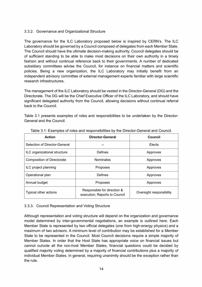
3.3.2. Governance and Organizational Structure The governance for the ILC Laboratory proposed below is inspired by CERN’s. The ILC Laboratory should be governed by a Council composed of delegates from each Member State. The Council should have the ultimate decision-making authority. Council delegates should be of sufficient standing to be able to make most decisions on their own authority in a timely fashion and without continual reference back to their governments. A number of dedicated subsidiary committees advise the Council, for instance on financial matters and scientific policies. Being a new organization, the ILC Laboratory may initially benefit from an independent advisory committee of external management experts familiar with large scientific research infrastructures. The management of the ILC Laboratory should be vested in the Director-General (DG) and the Directorate. The DG will be the Chief Executive Officer of the ILC Laboratory, and should have significant delegated authority from the Council, allowing decisions without continual referral back to the Council. Table 3.1 presents examples of roles and responsibilities to be undertaken by the Director-General and the Council.
Table 3.1: Examples of roles and responsibilities by the Director-General and Council. Action Director-General Council
Selection of Director-General -- Elects
ILC organizational structure Defines Approves
Composition of Directorate Nominates Approves
ILC project planning Proposes Approves
Operational plan Defines Approves
Annual budget Proposes Approves
Typical other actions Responsible for direction & execution; Reports to Council Oversight responsibility
3.3.3. Council Representation and Voting Structure Although representation and voting structure will depend on the organization and governance model determined by inter-governmental negotiations, an example is outlined here. Each Member State is represented by two official delegates (one from high-energy physics) and a maximum of two advisors. A minimum level of contribution may be established for a Member State to be represented in the Council. Most Council decisions require a simple majority of Member States. In order that the Host State has appropriate voice on financial issues but cannot outvote all the non-host Member States, financial questions could be decided by qualified majority voting determined by a majority of financial contributions plus a majority of individual Member States. In general, requiring unanimity should be the exception rather than the rule.

15
3.3.4. Laboratory and Project Management The Council elects the Director-General for a renewable fixed term. As scientific leader of the ILC Laboratory, the DG will: propose to the Council the organizational structure of the ILC Laboratory, including its advisory bodies; nominate members of the Directorate and other members of the top level of management for Council endorsement; direct ILC construction and operation; and report regularly to the Council. Under the direction of the DG, the Directorate will steer ILC construction and operation and will direct laboratory divisions in that task. The structure of the Directorate will be defined by the DG and approved by the Council. The structure may differ between the construction and operational phases. The structure of the Directorate should reflect critical facets of laboratory activity, such as civil engineering and conventional facilities, accelerator, and research program. The composition of the Directorate should reflect the expertise and experience required in all aspects, including project management, engineering and technology, and administration. Members of the Directorate will be nominated by the DG and endorsed by the Council for the term of the DG. During ILC construction, the laboratory organization must have well-defined project management and a well-defined project organization, to be defined by the DG. Given the size, technical complexity, and international nature of ILC construction, a dedicated project management team will be critical for success. With direction by the DG and by (or within) the Directorate, the project management team will be responsible for managing the construction of the ILC, including its cost and schedule, and including civil engineering, conventional facilities, and accelerator construction. The project management team should include, in addition to scientists and engineers, individuals with necessary expertise in working with the public sector, the private sector, international projects and organizations, and legal matters. This expertise could be brought in from outside the scientific community, if needed. The project organization and management should make provision for appropriate coordination and interfacing of global in-kind Member State contributions. It should be also noted that directly employing scientific staff at the ILC Laboratory will be important for the scientific atmosphere of the ILC Laboratory, to attract scientists to spend time at the Laboratory and to motivate the technical and administrative staff. The technical and management expertise and experience in large scientific projects and their construction that is resident in the leading laboratories of the Member States should be provided to advise the project and to address unforeseen issues when they arise. For instance, a wealth of know-how and expertise from manufacture of cryomodules and construction of light source facilities exists in the prospective Member States. The management practices used for large science projects are relatively well-established and will be followed for the ILC.15
15 Sec. 5 of ILC-PIP (Rev. C, July 2015).
16
3.3.5. Interface between ILC Laboratory and Experiments The ILC Laboratory should develop a successful scientific program in collaboration with the worldwide scientific community. It should define the process to be used to select experiments. The ILC detector collaborations are expected to be self-organizing and governing. Following the tradition of experiments at large colliders, participation in the experiments is expected to be open to the entire community. The ILC Laboratory should supply the necessary infrastructure and services for experiments. It should propose a scheme to decide the precise running program after consultation with the scientific community. In order to strengthen the liaison between the ILC Laboratory and the detector collaborations, it is suggested that the collaborations be mandated to designate individuals in their management structure who are responsible for (a) financial matters and (b) matters of safety of personnel and equipment, and that these individuals should be staff members of the ILC Laboratory during their tenure in these designated roles.

17
4. Technical Preparation Plan in Response to MEXT’s ILC Advisory Panel and the Science Council of Japan (SCJ)
A short summary of the current status of the ILC accelerator is given in Appendix E. 4.1. Technical Preparation Plan of the Main Preparatory Phase The technical preparation plan defines all activities necessary during the main preparatory phase to prepare for the construction phase of the ILC. It is part of the KEK-ILC Action plan, which describes the ILC project in three phases: (a) pre-preparatory phase, (b) main preparatory phase, and (c) construction phase (See Figure 3.1.). KEK released the KEK-ILC Action Plan in 2016. It was updated for ILC25016 in 2018.17 The KEK-ILC Action Plan includes the tasks necessary to address the specific technical issues pointed out by MEXT’s ILC Advisory Panel (Table 4.1) and the SCJ report (Table 4.2). It also describes the human resources necessary in the main preparatory phase. The technical preparation plan will be conducted by the ILC Pre-Lab. The plan assumes that most of the preparatory tasks will be carried out through international collaboration. The technical preparation plan described in the KEK-ILC Action Plan includes the following preparatory tasks and identifies the required budget:
(a) development of accelerator systems and components that addresses MEXT’s ILC Advisory Panel and SCJ technical concerns (approximately 20% of budget),
(b) civil engineering (geological survey, engineering design, etc.) (approx. 30%), (c) Hub-Lab/pilot plant in Japan (approx. 20%), (d) detailed engineering design of accelerator components (approx. 10%), (e) labor cost in addition to existing human resources (approx. 20%).
KEK will be responsible for civil engineering tasks, including environmental conservation and safety, through industry-academia collaboration. It will also promote construction of a Hub-lab/pilot plant with cavity and cryomodule manufacturing capabilities in Japan. The other preparatory tasks, including detailed engineering design of accelerator components, will be accomplished with international collaborators. The development tasks that address MEXT’s ILC Advisory Panel and SCJ technical concerns are discussed in Section 4.2. The 2018 E-JADE Report “The European ILC Preparation Plan”18 [EIPP] complements the KEK-ILC Action Plan and provides an overview of European expertise and possible contributions to the project during the main preparatory phase. The white paper from the European ILC community19 [EILC] to the European Strategy for Particle Physics Update also
16 L. Evans and S. Michizono (2017). The International Linear Collider Machine Staging Report 2017. https://arxiv.org/pdf/1711.00568.pdf 17 KEK (rev. 2018). KEK-ILC Action Plan. https://www.kek.jp/en/newsroom/KEK-ILC_ActionPlan_Addendum-EN%20%281%29.pdf 18 Horizon 2020 / E-JADE Report (2018). The European ILC Preparation Plan. https://www.e-jade.eu/sites/sites_custom/site_e-jade/content/e49893/e65922/e73204/ILC-EIPP.E-JADE.v2.12.20180703.pdf 19 P. Bambade et al. (2019). The International Linear Collider. A European Perspective. https://arxiv.org/pdf/1901.09825.pdf
18
identifies possible contributions to technical preparation. The EIPP identifies the following areas for potential European contributions to technical preparations: • SCRF:
- Cost reduction of the cavity fabrication process - Fundamental power couplers - Automation of module assembly - Dissemination of know-how and experience across labs participating in preparatory
efforts • High-efficiency klystrons • System design of highly reliable, high-efficiency cryogenic plants • System design of accelerator components:
- Positron source - Damping ring - Beam delivery system - Low-emittance beam transport - Beam dump
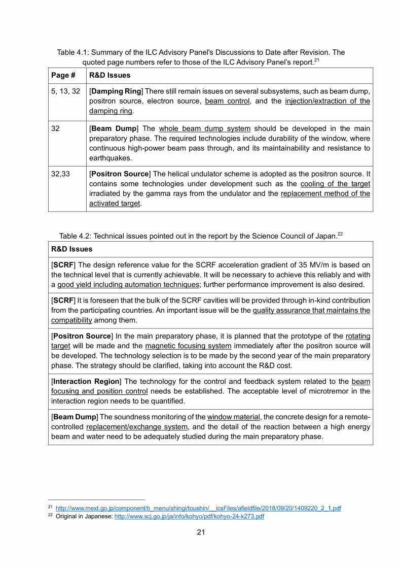
It is assumed that collaboration with the United States on the ILC accelerator during the main preparatory phase will be based upon ongoing R&D programs in the US-Japan R&D collaboration and on past and recent US accelerator activities on the ILC and other accelerators. For example, the US-Japan R&D collaboration for SCRF cost reduction and performance improvement, which started in 2017, is expected to contribute to finalizing the method for cost-effective cavity production. While the primary goal of technical preparation during the main preparatory phase is to complete the ILC250 accelerator technology, technical preparation will cultivate a younger generation of international scientists and engineers skilled in accelerator and beam operation technologies, and who can be expected to play crucial roles during ILC250 construction and operation. 4.2. Specific Items Identified by MEXT’s ILC Advisory Panel and the SCJ report Technical preparation in response to the specific items pointed out by MEXT’s ILC Advisory Panel and in the SCJ report will be performed based on the KEK-ILC Action Plan, the EIPP, and past and recent ILC accelerator R&D activities. These items are expected to be resolved during the main preparatory phase using a well-defined budget corresponding to approximately 20% of the total estimated budget for the technical preparation plan. Accelerator-related technical preparation tasks and possible partners for international collaboration as envisioned by KEK are summarized in Table 4.3 and discussed below, with emphasis on possible international partners. Possible partners among European countries and CERN are identified based on the EIPP and EILC. SCRF cavity and cryomodule production: SCJ and MEXTs’ ILC Advisory Panel had technical concerns about maintaining cavity quality during mass production and cryomodule assembly. The plan is to demonstrate prototype manufacturing using a new cost-effective production method on the scale of 1% of the full production, corresponding to about 100
19
cavities in the main preparatory phase. Half of the cavities will be produced in Japan and the other half in other regions/countries. The performance of the cavities will be evaluated to test their yields, and plug-compatibility will be checked. Other components, such as couplers and tuners, are also expected to improve in terms of performance; they will also be manufactured, and their yields will be evaluated. Overall testing after assembling these parts into a cryomodule will be the final step of evaluating the performance as an accelerator component. The US and Europe have significant experience in cavity production and in formulation of countermeasures against performance degradation after cryomodule assembly. It is anticipated that Germany and the US will work on cost reduction of the cavity fabrication process and on reproducibility and high yield of cavity performance at the design gradient, while France could play a leading role in automation of cryomodule assembly. SCRF cryomodule transport: SCJ and MEXTs’ ILC Advisory Panel also had technical concerns about the effect of cryomodule transport on cavity performance. Europe and the US have significant experience with land transportation of cryomodules. This experience needs to be extended to marine transport, while assuring that performance is maintained. In order to demonstrate performance preservation after transport, multiple cryomodules meeting ILC specifications will be manufactured in the main preparatory phase, and after initial performance testing, they will be delivered to another region, where their performance will be tested again. This work will be performed by international cooperation among KEK and institutes in the US and Europe by transporting cryomodules between two or more regions. It will also provide an opportunity to establish an SCRF hub laboratory in Japan. Positron source: SCJ and MEXT’s ILC Advisory Panel had technical concerns about the rotating target, particularly its system design and the need for a plan for replacing activated targets, and about the magnetic focusing system. System designs for monitoring the reliability of the equipment and for remote handling to replace the rotating target will be performed in the main preparatory phase. Germany and the US possess experience from having studied positron sources for the ILC during the GDE process. In addition, CERN, France, and Russia possess expertise in positron sources. They could all be important partners for system design of the rotating target and the magnetic focusing devices. KEK will lead an industry-academia joint effort to develop the system design of the remote handling system for replacing the rotating target while ensuring environmental and radiation safety. In addition to these tasks pointed out by MEXT and SCJ, the KEK-ILC Action Plan recognizes that a system design of the photon dump system of the positron source is needed. CERN, Germany, and the US could become important partners in carrying out this system design of the photon dump, building upon Germany’s extensive experience in system design for the undulator positron source and upon experience of CERN and the US in operating high-power beam dumps. Design of an electron-driven positron source as a backup technology will also be continued. Damping Ring: MEXT’s ILC Advisory Panel had technical concerns, as described in the MEXT’s commissioned research/survey report 20 [NRI], about several damping ring subsystems, including stability and reliability of the injection and extraction kicker systems and necessity for a high-resolution fast feedback system. System design of the fast feedback system in the damping ring could be performed by a collaboration between Japan and Italy,
20 Nomura Research Institute, Report commissioned by MEXT on the ILC (2016). Analysis report on the technical feasibility concerning the ILC project. (Original in Japanese)
20
and tests will be performed at SuperKEKB at KEK. SuperKEKB has a circumference close to that of the ILC damping ring and a feedback system similar to ILC250. System development of the high-resolution fast feedback system for the ILC will be performed based on experience of the system operation and upgrade development at SuperKEKB. For its injection and extraction system, fast kicker magnets and a fast-pulsed power source have been developed, and multiple kicker systems have already been operated under beam operation. The remaining task is to ensure the stability and reliability over long-term operation. A long-term stability test of the fast kicker system will be performed at the Accelerator Test Facility (ATF) at KEK. Furthermore, international collaboration is foreseen on upgrading and improving the reliability of the fast kicker system for the damping ring. CERN and Italy could be important partners for the system design of the injection and extraction system, as they have been studying fast kickers since the GDE process. Interaction Region: SCJ stated technical concerns about the technology of the control and feedback system and about long-term stability of beam focus and position. The beam size at the ATF2 focal point is designed to be 37 nm, which is technically equivalent to a beam size of 7 nm for ILC250. At ATF2, the achieved beam size is smaller than 41 nm, which is consistent with the design beam size. The ILC prototype feedback system has been verified to satisfy all ILC requirements. Beam focusing and position control for the ILC final focus system have been studied at ATF2 at KEK. Based on the final-focus R&D experience at ATF2 at KEK and for CLIC, a long-term stability study of beam focusing and position control for the ILC final focus system will continue through collaboration with CERN and the UK. Beam Dump: SCJ and MEXT’s ILC Advisory Panel stated technical concerns regarding: reliability, earthquake protection, and stability of the window of the main beam dump; reaction between the high energy beam and water; and containment of activated water. In the main preparatory phase, the scheme for monitoring the integrity of the beam dump window will be studied and the system design for items such as the containment of activated water will be performed. CERN operates beam dumps for large accelerators and high-power beam dumps, and the US operates water-circulated beam dumps. They could be important partners for the system design of the beam dump. KEK will lead the system design of the beam dump facilities, ensuring environmental and radiation safety with cooperation from the government, industry, and the scientific community.
21
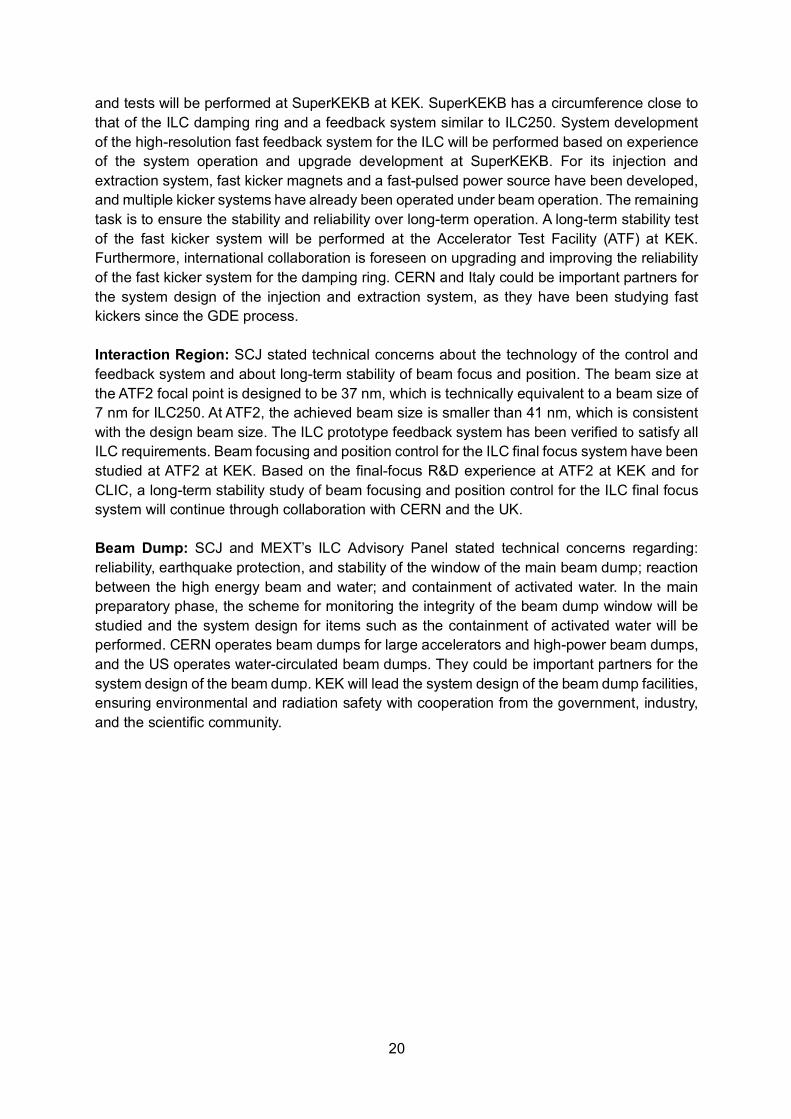
Table 4.1: Summary of the ILC Advisory Panel's Discussions to Date after Revision. The quoted page numbers refer to those of the ILC Advisory Panel’s report.21
Page # R&D Issues
5, 13, 32 [Damping Ring] There still remain issues on several subsystems, such as beam dump, positron source, electron source, beam control, and the injection/extraction of the damping ring.
32 [Beam Dump] The whole beam dump system should be developed in the main preparatory phase. The required technologies include durability of the window, where continuous high-power beam pass through, and its maintainability and resistance to earthquakes.
32,33 [Positron Source] The helical undulator scheme is adopted as the positron source. It contains some technologies under development such as the cooling of the target irradiated by the gamma rays from the undulator and the replacement method of the activated target.
Table 4.2: Technical issues pointed out in the report by the Science Council of Japan.22
R&D Issues
[SCRF] The design reference value for the SCRF acceleration gradient of 35 MV/m is based on the technical level that is currently achievable. It will be necessary to achieve this reliably and with a good yield including automation techniques; further performance improvement is also desired.
[SCRF] It is foreseen that the bulk of the SCRF cavities will be provided through in-kind contribution from the participating countries. An important issue will be the quality assurance that maintains the compatibility among them.
[Positron Source] In the main preparatory phase, it is planned that the prototype of the rotating target will be made and the magnetic focusing system immediately after the positron source will be developed. The technology selection is to be made by the second year of the main preparatory phase. The strategy should be clarified, taking into account the R&D cost.
[Interaction Region] The technology for the control and feedback system related to the beam focusing and position control needs be established. The acceptable level of microtremor in the interaction region needs to be quantified.
[Beam Dump] The soundness monitoring of the window material, the concrete design for a remote-controlled replacement/exchange system, and the detail of the reaction between a high energy beam and water need to be adequately studied during the main preparatory phase.
21 http://www.mext.go.jp/component/b_menu/shingi/toushin/__icsFiles/afieldfile/2018/09/20/1409220_2_1.pdf 22 Original in Japanese: http://www.scj.go.jp/ja/info/kohyo/pdf/kohyo-24-k273.pdf
22
Table 4.3: Accelerator-related technical preparation tasks and possible partners for
international collaboration as envisioned by KEK.
Component Issue Summary of tasks Candidates for collaboration
SCRF Cavity
Mass production incl. automation
Performance statistics, mass production technology
France, Germany, US
Cryomodule transport
Performance assurance after transport France, Germany, US
Positron Source
Rotating target Exchanging target, system design
CERN, France, Germany, US + industry-academia efforts
Magnetic focusing system System design France, Germany, Russia, US
Photon dump23 System design CERN, Germany, US
Damping Ring
Fast kicker Test of long-term stability, system design CERN, Italy
Feedback Test at SuperKEKB Italy
Interaction Region
Beam focus/position control
Test of long-term stability CERN, UK
Beam Dump
Total system System design CERN, US
Beam window, cooling water circulation
Durability, exchangeability, earthquake-resistance
CERN, US + industry-academia efforts
23 Since the system design of the photon dump system is a necessary task in the main preparatory phase, it is also listed here even though it is not pointed out by MEXT’s ILC Advisory Panel and SCJ.
23
5. Summary This document summarizes deliberations of the International Working Group on the ILC Project set up by KEK. Three aspects are studied, namely international cost sharing for ILC construction and operation, organization and governance, and international sharing of the remaining technical preparation. The document “Revised ILC Project Implementation Planning” produced under the LCB in July 2015 is used as a major reference. Developments since then have been taken into account. For instance, since November 2017, the baseline of the ILC has been a 250 GeV center-of-mass energy machine as a Higgs Factory. The Working Group has revisited issues considered in the Revised ILC-PIP and made proposals for relevant aspects. The basic principle of international cost sharing is the same as what is described in the Revised ILC-PIP. Civil engineering is a responsibility of the Host State, and accelerator components will be provided by Member States mostly as in-kind contributions. Construction of conventional facilities will be managed by the ILC Laboratory, and the Host State will provide a significant part of the conventional facilities as in-kind contributions. The operational cost should be shared among Member States. A model of the decommissioning cost sharing is proposed. The organization and governance of the ILC Laboratory were studied. The basic structure described in the Revised ILC-PIP is deemed to be appropriate. The organization and governance of the ILC Pre-Lab and its formation, evolution, and transition to the ILC Laboratory are described in detail. A technical preparation plan in response to MEXT’s ILC Advisory Panel report and the SCJ report is presented. Based on current expertise of various laboratories, technical capabilities are identified to carry out the technical preparation plan through international collaboration in the main preparatory phase. This document presents views from scientists concerning some important aspects of implementation of the ILC project. It is hoped that it is helpful for discussions among governments and funding authorities.

24
Appendices A. Charge to KEK International Working Group on the ILC Project May 17, 2019 KEK and the high energy physics community in Japan proposed in October 2012 that Japan host the International Linear Collider (ILC). Since then, the Ministry of Education, Culture, Sports, Science and Technology (MEXT) has been seriously investigating hosting the ILC project. A report was released by MEXT’s ILC Advisory Panel in July 2018, and in reply to the request of MEXT, the Science Council of Japan (SCJ) submitted the “Assessment of the Revised Plan of the International Linear Collider Project” to MEXT in December 2018. MEXT then presented its view in regard to the ILC project at the Linear Collider Board (LCB) meeting on March 7, 2019 in Tokyo. Although “MEXT has not yet reached declaration for hosting the ILC in Japan at this moment”, “MEXT will continue to discuss the ILC project with other governments while having an interest in the project.” At the same meeting, MEXT said it hoped that KEK will set up an international working group so that discussions within the community of domestic and international researchers would proceed on topics such as the international cost sharing. KEK is hereby establishing the International Working Group on the ILC Project, with close consultation with MEXT. The Working Group is charged to submit a report on the following points: l Model of international cost-sharing for construction and operation
Ø Study the construction cost of the 250 GeV ILC version (ILC250) based on the ILC-TDR cost estimate, and propose a model for the construction describing: (a) items that are appropriate for the host responsibility, and (b) items that should be shared by all partners. In addition, propose a model for sharing the operational and decommissioning cost.
l Organization and governance of the ILC Laboratory Ø Propose an organizational and governance model for the ILC Laboratory as well as
the ILC Pre-Lab. l International share of the remaining technical preparation
Ø Present a technical preparation plan for the preparatory phase to solve the technical issues pointed out in MEXT’s ILC Advisory Panel report and the SCJ report, including the possibility of international cooperation.
The “Revised ILC Project Implementation Planning (July 2015, Revision C)” can be used as a starting point of discussions: – http://ilcdoc.linearcollider.org/record/62116/files/PIP_complete_IssueC.pdf The Working Group is requested to submit a report to the KEK Director-General by the end of September 2019. The report will be submitted to MEXT and will be used by MEXT for discussions with other governments. A draft of the report should be available at the LCB meeting on August 7, 2019 for comments from the LCB members.
25
B. Member List of KEK International Working Group on the ILC Project Members: Klaus Desch (University of Bonn) Andy Lankford (University of California, Irvine) Kajari Mazumdar (Tata Institute of Fundamental Research) Patricia McBride (Fermi National Accelerator Laboratory) Shinichiro Michizono (KEK) Yasuhiro Okada (KEK) *Chair Claude Vallée (Centre de Physique des Particules de Marseille, CNRS-IN2P3 and Aix-Marseille University) Scientific Secretary: Keisuke Fujii (KEK) C. Member List of the Preparatory Group Keisuke Fujii (KEK) Shinichiro Michizono (KEK) Yasuhiro Okada (KEK) Toshiyuki Okugi (KEK) Taikan Suehara (Kyushu University) Tomohiko Tanabe (ICEPP, University of Tokyo) Nobuhiro Terunuma (KEK) Yasuchika Yamamoto (KEK) D. Meeting Records • 1st Meeting, May 17, 2019, in Granada • 2nd Meeting, June 19, 2019, video-conference • 3rd Meeting, July 9-10, 2019, at KEK • 4th Meeting, August 26, 2019, video-conference • 5th Meeting, September 12-13, 2019, at KEK
26
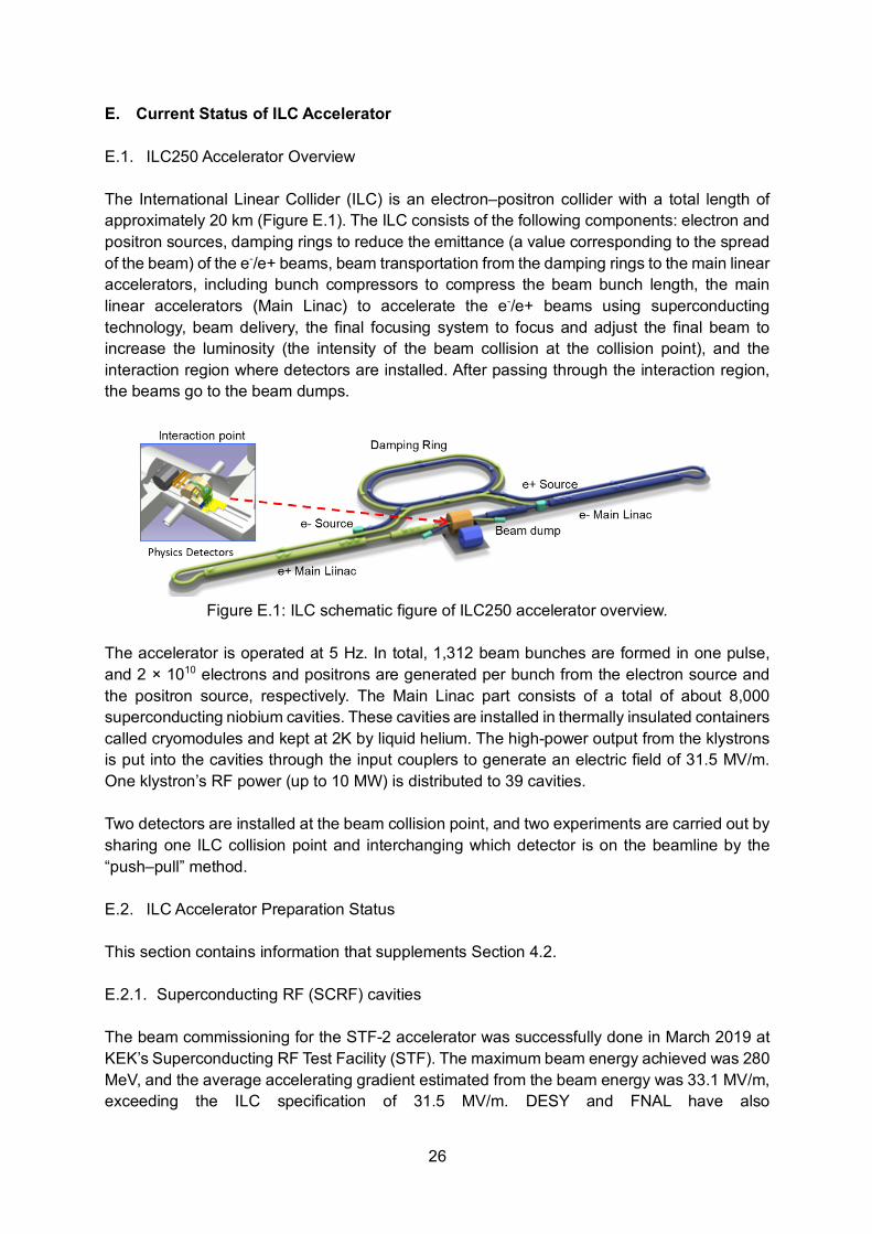
E. Current Status of ILC Accelerator E.1. ILC250 Accelerator Overview The International Linear Collider (ILC) is an electron–positron collider with a total length of approximately 20 km (Figure E.1). The ILC consists of the following components: electron and positron sources, damping rings to reduce the emittance (a value corresponding to the spread of the beam) of the e-/e+ beams, beam transportation from the damping rings to the main linear accelerators, including bunch compressors to compress the beam bunch length, the main linear accelerators (Main Linac) to accelerate the e-/e+ beams using superconducting technology, beam delivery, the final focusing system to focus and adjust the final beam to increase the luminosity (the intensity of the beam collision at the collision point), and the interaction region where detectors are installed. After passing through the interaction region, the beams go to the beam dumps.
Figure E.1: ILC schematic figure of ILC250 accelerator overview.
The accelerator is operated at 5 Hz. In total, 1,312 beam bunches are formed in one pulse, and 2 × 10¹⁰ electrons and positrons are generated per bunch from the electron source and the positron source, respectively. The Main Linac part consists of a total of about 8,000 superconducting niobium cavities. These cavities are installed in thermally insulated containers called cryomodules and kept at 2K by liquid helium. The high-power output from the klystrons is put into the cavities through the input couplers to generate an electric field of 31.5 MV/m. One klystron’s RF power (up to 10 MW) is distributed to 39 cavities. Two detectors are installed at the beam collision point, and two experiments are carried out by sharing one ILC collision point and interchanging which detector is on the beamline by the “push–pull” method. E.2. ILC Accelerator Preparation Status This section contains information that supplements Section 4.2. E.2.1. Superconducting RF (SCRF) cavities The beam commissioning for the STF-2 accelerator was successfully done in March 2019 at KEK’s Superconducting RF Test Facility (STF). The maximum beam energy achieved was 280 MeV, and the average accelerating gradient estimated from the beam energy was 33.1 MV/m, exceeding the ILC specification of 31.5 MV/m. DESY and FNAL have also
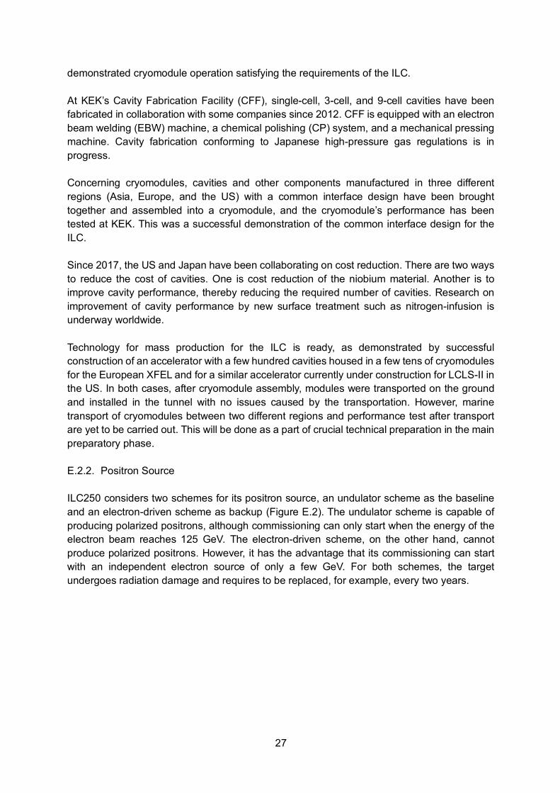
27
demonstrated cryomodule operation satisfying the requirements of the ILC. At KEK’s Cavity Fabrication Facility (CFF), single-cell, 3-cell, and 9-cell cavities have been fabricated in collaboration with some companies since 2012. CFF is equipped with an electron beam welding (EBW) machine, a chemical polishing (CP) system, and a mechanical pressing machine. Cavity fabrication conforming to Japanese high-pressure gas regulations is in progress. Concerning cryomodules, cavities and other components manufactured in three different regions (Asia, Europe, and the US) with a common interface design have been brought together and assembled into a cryomodule, and the cryomodule’s performance has been tested at KEK. This was a successful demonstration of the common interface design for the ILC. Since 2017, the US and Japan have been collaborating on cost reduction. There are two ways to reduce the cost of cavities. One is cost reduction of the niobium material. Another is to improve cavity performance, thereby reducing the required number of cavities. Research on improvement of cavity performance by new surface treatment such as nitrogen-infusion is underway worldwide. Technology for mass production for the ILC is ready, as demonstrated by successful construction of an accelerator with a few hundred cavities housed in a few tens of cryomodules for the European XFEL and for a similar accelerator currently under construction for LCLS-II in the US. In both cases, after cryomodule assembly, modules were transported on the ground and installed in the tunnel with no issues caused by the transportation. However, marine transport of cryomodules between two different regions and performance test after transport are yet to be carried out. This will be done as a part of crucial technical preparation in the main preparatory phase. E.2.2. Positron Source ILC250 considers two schemes for its positron source, an undulator scheme as the baseline and an electron-driven scheme as backup (Figure E.2). The undulator scheme is capable of producing polarized positrons, although commissioning can only start when the energy of the electron beam reaches 125 GeV. The electron-driven scheme, on the other hand, cannot produce polarized positrons. However, it has the advantage that its commissioning can start with an independent electron source of only a few GeV. For both schemes, the target undergoes radiation damage and requires to be replaced, for example, every two years.

28
Figure E.2: Schematic figure of ILC positron source schemes. (a) undulator scheme, (b)
electron-driven scheme. In the undulator scheme, the electron beam is accelerated in the main linac and travels through a 231 m long superconducting helical undulator. Photons produced in the undulator are sent downstream and hit a rotating titanium-alloy target with a radiation length of 0.2. Positrons are then produced through electron-positron pair creation. The resulting positron beam can reach a polarization of 30% without special equipment, which can be enhanced to approximately 60% by introducing photon collimators. A prototype of two high-field short-period superconducting helical undulators for the ILC positron source was developed by STFC Daresbury. The magnetic field of the prototype satisfied the requirement for ILC250. A magnetic bearing is used to rotate the 50-cm radius titanium-alloy target at a rotation speed of 2000 rpm. The heat load on the target is relatively small, approximately 2 kW. Magnetic bearings have been used under much harsher conditions, for instance at gas plants, where the weight and rotation speed exceed those for the ILC250 target. The produced positrons are efficiently collected using a magnetic focusing device. A quarter-wave transformer (QWT) with a pulse width of 1 ms and a maximum magnetic field of 1 T is used as the magnetic focusing device. At KEKB, there is long-term experience of operating a QWT with a magnetic field which is twice that of ILC250 at the same duty cycle as ILC250 (Its pulse length is one-tenth of the ILC but its repetition rate is ten times higher.). The photons used for positron production eventually enter a photon dump, depositing a power of approximately 60 kW. There are two candidate schemes for the photon dump, a water curtain scheme and a graphite scheme; conceptual designs have been completed for both. In the electron-driven scheme, a normal-conducting linac is used to produce an electron beam of a few GeV, which then hits a metal target. Positrons are extracted from the produced electron-positrons pairs. In the present scheme, positron beams with a bunch structure that is consistent with storage in the damping ring are injected in 20 pulses within a time window of approximately 63 ms. By stretching the time duration of the electron beam hitting the target, the heat load on the target can be mitigated.
29
In the electron-driven scheme, a tungsten alloy target with a 25-cm radius is rotated at a rotation speed of 225 rpm using a bearing system with ferrofluid rotating seal. The heat load of approximately 20 kW on the target is to be directly cooled with cooling water under high vacuum. There already exists operational experience at Nagoya University with a fast-rotating target for an X-ray generator, albeit at a different degree of vacuum, with a heat load of 90 kW. Tests of the ferrofluid rotating seal are being carried out at KEK and Hiroshima University, under the vacuum pressure of 10-6 Pa required for ILC250. For the magnetic focusing device, an adiabatic matching device (AMD) with a pulse width of 25 μs, a maximum magnetic field of 5 T, and a minimum inner diameter of 16 mm will be used. There is operational experience at SLC and SuperKEKB with using an AMD with a pulse width of 5 μs, a maximum magnetic field of 3.5 T, and a minimum inner diameter of 7 mm. For VLEPP-5 at BINP, there is operational experience with a maximum magnetic field of 10 T. E.2.3. Damping Ring The damping rings are circular accelerators which are placed after the electron and positron sources with the goal of creating high-quality electron and positron beams for the ILC. The circumference of the damping rings is approximately 3.2 km, corresponding to about 1/90 of the beam pulse length at the electron and positron sources and at the main linac. A fast kicker system compresses and decompresses the beam pulse during its injection and extraction, respectively. An injection-extraction system using a fast kicker has been under active development since the GDE period. At KEK, the necessary performance was demonstrated in a test of beam injection-extraction system at the ATF damping ring, by using a pulsed power source satisfying ILC250 specifications for ramping time and repetition rate. A fast kicker using a fast-pulsed power source is being developed at INFN-LNF, SLAC, and CERN. They are foreseen to be collaboration partners for system development including assurance of long-term reliability of the injection-extraction system. The feedback system, which is one of the issues pointed out by MEXT’s ILC Advisory Panel, is based on an ultrafast programmable electronic circuit and is used to stabilize the beam in the damping ring. This fast feedback system is being developed along the lines similar to systems already realized for many existing storage rings. Specifically, the six-dimensional fast feedback system currently in use for DAΦNE at INFN-LNF is the basis for the R&D program of the fast feedback system for the ILC damping ring. Although it is stated in the TDR that a 14-16 bit analog-to-digital converter is needed, it is envisioned that a 12-bit feedback system may be sufficient for the ILC damping ring, which will be tested at SuperKEKB. E.2.4. Interaction Region The final focus system of the ILC is the beamline after the main linac. The main purpose of the final focus system is to squeeze the electron and positron beams at the interaction point while accurately controlling their positions. The ATF2 beamline was designed and constructed by an international collaboration as a facility to test the design of the ILC final focus system. Beam tuning of the ATF2 beamline is also being done as a project of the international ATF collaboration. A large number of domestic and
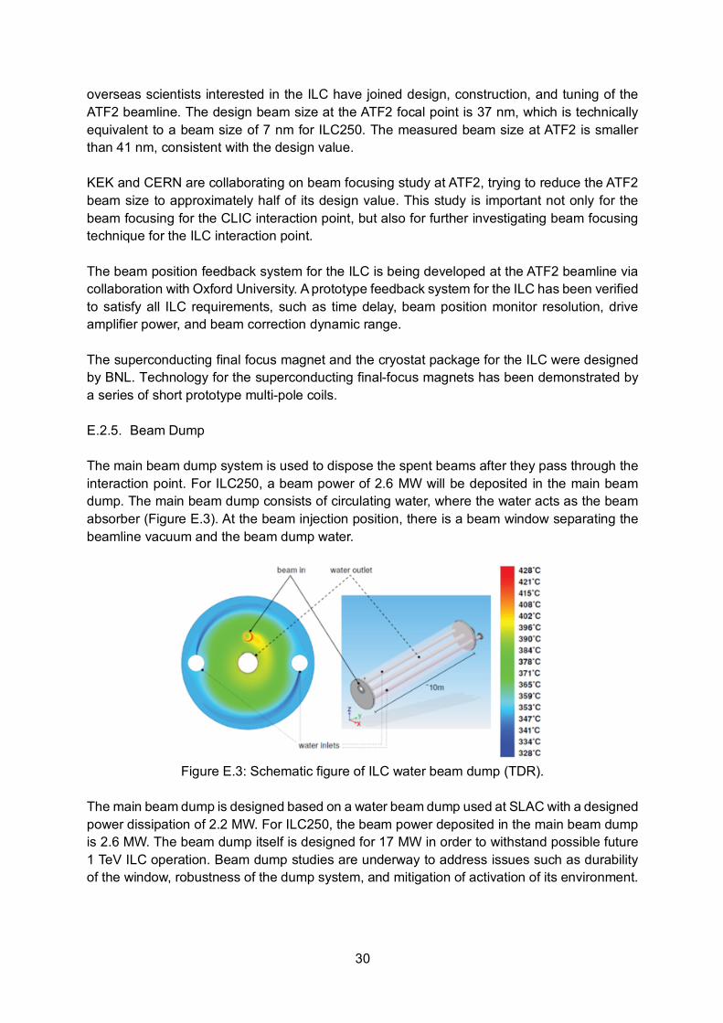
30
overseas scientists interested in the ILC have joined design, construction, and tuning of the ATF2 beamline. The design beam size at the ATF2 focal point is 37 nm, which is technically equivalent to a beam size of 7 nm for ILC250. The measured beam size at ATF2 is smaller than 41 nm, consistent with the design value. KEK and CERN are collaborating on beam focusing study at ATF2, trying to reduce the ATF2 beam size to approximately half of its design value. This study is important not only for the beam focusing for the CLIC interaction point, but also for further investigating beam focusing technique for the ILC interaction point. The beam position feedback system for the ILC is being developed at the ATF2 beamline via collaboration with Oxford University. A prototype feedback system for the ILC has been verified to satisfy all ILC requirements, such as time delay, beam position monitor resolution, drive amplifier power, and beam correction dynamic range. The superconducting final focus magnet and the cryostat package for the ILC were designed by BNL. Technology for the superconducting final-focus magnets has been demonstrated by a series of short prototype multi-pole coils. E.2.5. Beam Dump The main beam dump system is used to dispose the spent beams after they pass through the interaction point. For ILC250, a beam power of 2.6 MW will be deposited in the main beam dump. The main beam dump consists of circulating water, where the water acts as the beam absorber (Figure E.3). At the beam injection position, there is a beam window separating the beamline vacuum and the beam dump water.
Figure E.3: Schematic figure of ILC water beam dump (TDR).
The main beam dump is designed based on a water beam dump used at SLAC with a designed power dissipation of 2.2 MW. For ILC250, the beam power deposited in the main beam dump is 2.6 MW. The beam dump itself is designed for 17 MW in order to withstand possible future 1 TeV ILC operation. Beam dump studies are underway to address issues such as durability of the window, robustness of the dump system, and mitigation of activation of its environment.