Embed Size (px)
Citation preview
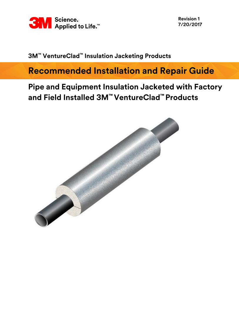
3M™ VentureClad™ Insulation Jacketing Products
Recommended Installation and Repair Guide
Pipe and Equipment Insulation Jacketed with Factory
and Field Installed 3M™ VentureClad™ Products
Revision 1 7/20/2017
Page 1 of 48
3M™ VentureClad™ Insulation Jacketing Products Recommended Installation and Repair Guidelines, Revision 1
Table of Contents
1. Scope ................................................................................................................................. Page 2
2. Notes ................................................................................................................................. Page 3
3. Installing straight sections of preformed pipe insulation
that has been factory‐jacketed ........................................................................................ Page 4
4. Field installation of 3M™ VentureClad™ Jacket over insulated straight pipe ............. Page 14
5. Installing factory-jacketed fittings ................................................................................. Page 17
6. Installing factory‐fabricated or field‐fabricated valve insulation .............................. Page 30
7. Using 3M™ VentureClad™ to jacket an insulated, small diameter storage tank .......... Page 33
8. Using insulation boards, factory jacketed with 3M™ VentureClad™ Product, to
insulate a large diameter horizontal storage tank operating
at temperatures from ambient up to 350°F ..................................................................Page 34
9. Using 3M™ VentureClad™ Insulation Jacketing Product
to jacket an insulated heat exchanger ..........................................................................Page 38
10. Repair of punctures and tears of the 3M™ VentureClad™ Product ..............................Page 39
11. Using 3M™ VentureClad™ Product to jacket an insulated pipe
that penetrates an exterior wall ..................................................................................... Page 41
Product Key
1577CW Smooth silver aluminum with adhesive
1577CW-E Embossed silver aluminum with adhesive
1577NA Smooth silver aluminum without adhesive
1577CW-CM/WM/BM Smooth silver aluminum, white, or black with adhesive and a membrane
1579GCW Heavy duty, smooth silver aluminum with adhesive
1579GCW-E Heavy duty, embossed silver aluminum with adhesive
1579GNA Heavy duty, smooth silver aluminum without adhesive
1579GCW-CM/WM Smooth silver aluminum and white with adhesive and a membrane
Page 2 of 48
3M™ VentureClad™ Insulation Jacketing Products Recommended Installation and Repair Guidelines, Revision 1
1. Scope
a. Using 3M™ VentureClad™ products 1577CW, 1579GCW, and 1579GNA, the following
recommended installation guidelines apply when installing these materials to rigid or semi‐
rigid pipe insulation materials. It will apply to either factory or field jacketing. “CW” products
have a pressure sensitive adhesive, covered with a release liner, over their entire inside
surface. “NA” products have no adhesive.
b. 1577CW, 1579GCW, and 1579GNA are suitable for both indoor and outdoor applications but
not for below ground, buried applications. It is recommended that either 1577CW pressure
sensitive tape be used for sealing all 1579GCW and 1579GNA seams, whether they are lap or
butt joints, or the more flexible 1578CW tape. The 1577CW tape may be used for both
securement and sealing the insulation sections/segments against both water and water vapor
intrusion. The 1578CW tape is only to be used for sealing the insulation sections/segments
against water and water vapor intrusion in recommended locations. 4-inch (100mm) wide
seaming tape should be considered the standard if not recommended otherwise.
c. Although the figures within this manual show the 3M™ VentureClad™ and 3M™ Venture Tape™
products with an embossed and smooth aluminum finish, they are also available in
other colors.
d. Insulation materials for which these procedures are applicable include, but are not
necessarily limited to, the following: polystyrene, polyisocyanurate, phenolic foam, cellular
glass, flexible elastomeric, polyolefin, faced or unfaced fiberglass, mineral wool, molded
expanded perlite, flexible aerogel, and calcium silicate.
e. These procedures assume the piping will operate at below ambient temperatures and
therefore include sealing against water vapor intrusion. For below ambient applications,
where condensation control is required, it may be beneficial to select a 3M™ VentureClad™
product with a high emittance (i.e., > 0.5) to reduce the insulation thickness required to
prevent surface condensation. Since all the 3M™ VentureClad™ products covered by this
manual will have a low water vapor permeance, no additional vapor retarder needs to be
used so long as the 3M™ VentureClad™ is sealed tightly at all locations.
f. The maximum use temperature of the Natural Aluminum 3M™ VentureClad™ products is
300°F (149°C). The maximum use of the Membrane 3M™ VentureClad™ products is 248°F
(120°C). The pipe service temperature itself may be much higher on above ambient service.
In those cases, the exposure temperature of the 3M™ VentureClad™ should be controlled to
below 300°F by the design and installation of the insulation system.
g. Proper adhesion of the materials is paramount in the long term success of the jacketing
and the tape products. It is recommended that for both the 3M™ VentureClad™ and the
3M™ Venture Tape™, the installer keep the adherent surfaces free of dust, dirt, and water.
It is recommended that the applicator is to seal immediately once this adhesive is exposed by
removing the release liner.
Page 3 of 48
3M™ VentureClad™ Insulation Jacketing Products Recommended Installation and Repair Guidelines, Revision 1
2. Notes that apply to the installation of 3M™ VentureClad™ jacketing on insulated pipes:
Note 1: The guidelines in this manual do not purport to address all engineering issues associated with the
use of 3M™ VentureClad™ jacketing products and pipe insulation system design. It is the responsibility of
the facility owner to have (1) qualified structural engineers perform calculations, as required, to make
certain that the securement is sufficient, accounting for the weight of the insulation system; (2) qualified
mechanical engineers determine the insulation meets the required thermal requirements and (3) qualified
corrosion engineers to specify type and thicknesses of insulation materials and coatings to protect the
metal surfaces from corrosion under insulation.
Note 2: Users of this manual should use only trained, skilled, and experienced insulation workers. The
guidelines included in this manual are not of sufficient detail to advise the installer of all techniques
required to install insulation systems correctly.
Note 3: The guidelines in this manual do not purport to address all of the safety concerns, if any,
associated with its use. It is the responsibility of the user of this manual to establish appropriate safety
and health practices and determine the applicability of regulatory limitations prior to use.
Note 4: 3M strongly recommends the facility owner/operator to conduct regular pipe and equipment
insulation system maintenance. Damaged insulation systems can perform poorly and allow ingress of
water from rain or melting snow or, on below ambient systems, water vapor intrusion with subsequent
condensation. Wet insulation will not perform thermally on a par with that provided by the insulation
material’s manufacturer; further, it can lead to corrosion under insulation. The best prevention of
these problems is a proactive insulation system maintenance program that includes sealing of the
3M™ VentureClad™ jacketing.
Note 5: 3M generally recommends the use of 3M™ Venture Tape™ 1577CW as a seaming tape with both
3M™ VentureClad™ 1577CW and 1579GCW products. In situations where extremely tight corners are
required, the more flexible, 3M™ Venture Tape™ 1578CW product is acceptable.
Page 4 of 48
3M™ VentureClad™ Insulation Jacketing Products Recommended Installation and Repair Guidelines, Revision 1
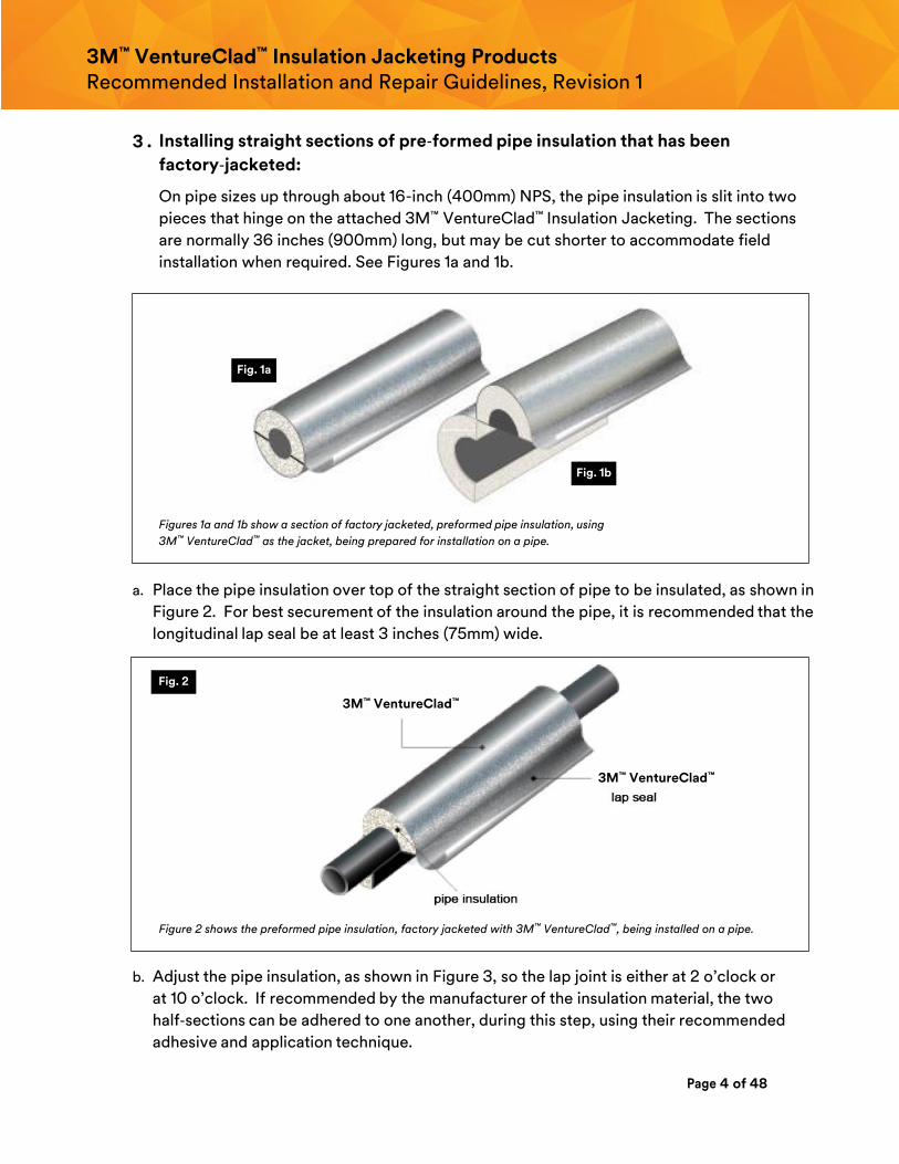
3 . Installing straight sections of pre‐formed pipe insulation that has been
factory‐jacketed:
On pipe sizes up through about 16-inch (400mm) NPS, the pipe insulation is slit into two
pieces that hinge on the attached 3M™ VentureClad™ Insulation Jacketing. The sections
are normally 36 inches (900mm) long, but may be cut shorter to accommodate field
installation when required. See Figures 1a and 1b.
Figures 1a and 1b show a section of factory jacketed, preformed pipe insulation, using
3M™ VentureClad™ as the jacket, being prepared for installation on a pipe.
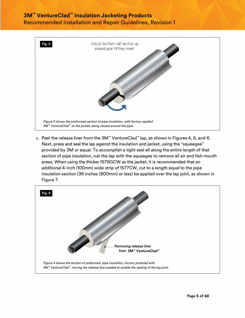
a. Place the pipe insulation over top of the straight section of pipe to be insulated, as shown in
Figure 2. For best securement of the insulation around the pipe, it is recommended that the
longitudinal lap seal be at least 3 inches (75mm) wide.
Figure 2 shows the preformed pipe insulation, factory jacketed with 3M™ VentureClad™, being installed on a pipe.
b. Adjust the pipe insulation, as shown in Figure 3, so the lap joint is either at 2 o’clock or
at 10 o’clock. If recommended by the manufacturer of the insulation material, the two
half‐sections can be adhered to one another, during this step, using their recommended
adhesive and application technique.
Fig. 1a
Fig. 1b
Fig. 2
3M™ VentureClad™
3M™ VentureClad™
Page 5 of 48
3M™ VentureClad™ Insulation Jacketing Products Recommended Installation and Repair Guidelines, Revision 1
Figure 3 shows the preformed section of pipe insulation, with factory applied
3M™ VentureClad™ as the jacket, being closed around the pipe.
c. Peel the release liner from the 3M™ VentureClad™ lap, as shown in Figures 4, 5, and 6.
Next, press and seal the lap against the insulation and jacket, using the “squeegee”
provided by 3M or equal. To accomplish a tight seal all along the entire length of that
section of pipe insulation, rub the lap with the squeegee to remove all air and fish-mouth
areas. When using the thicker 1579GCW as the jacket, it is recommended that an
additional 4-inch (100mm) wide strip of 1577CW, cut to a length equal to the pipe
insulation section (36 inches (900mm) or less) be applied over the lap joint, as shown in
Figure 7.
Figure 4 shows the section of preformed pipe insulation, factory jacketed with
3M™ VentureClad™, having the release liner peeled to enable the sealing of the lap joint.
Fig. 3
Fig. 4
3M™ VentureClad™
Page 6 of 48
3M™ VentureClad™ Insulation Jacketing Products Recommended Installation and Repair Guidelines, Revision 1
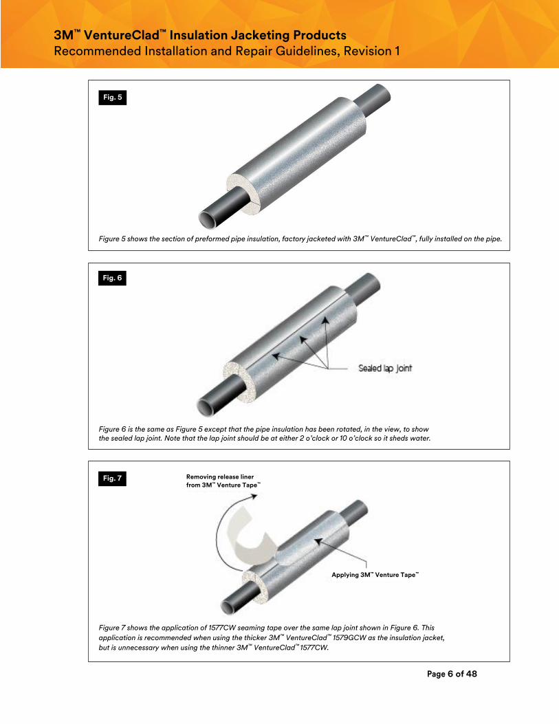
Figure 5 shows the section of preformed pipe insulation, factory jacketed with 3M™ VentureClad™, fully installed on the pipe.
Figure 6 is the same as Figure 5 except that the pipe insulation has been rotated, in the view, to show the sealed lap joint. Note that the lap joint should be at either 2 o’clock or 10 o’clock so it sheds water.
Figure 7 shows the application of 1577CW seaming tape over the same lap joint shown in Figure 6. This
application is recommended when using the thicker 3M™ VentureClad™ 1579GCW as the insulation jacket,
but is unnecessary when using the thinner 3M™ VentureClad™ 1577CW.
Fig. 5
Fig. 6
Fig. 7 Removing release liner
from 3M™ Venture Tape™
Applying 3M™ Venture Tape™
Page 7 of 48
3M™ VentureClad™ Insulation Jacketing Products Recommended Installation and Repair Guidelines, Revision 1
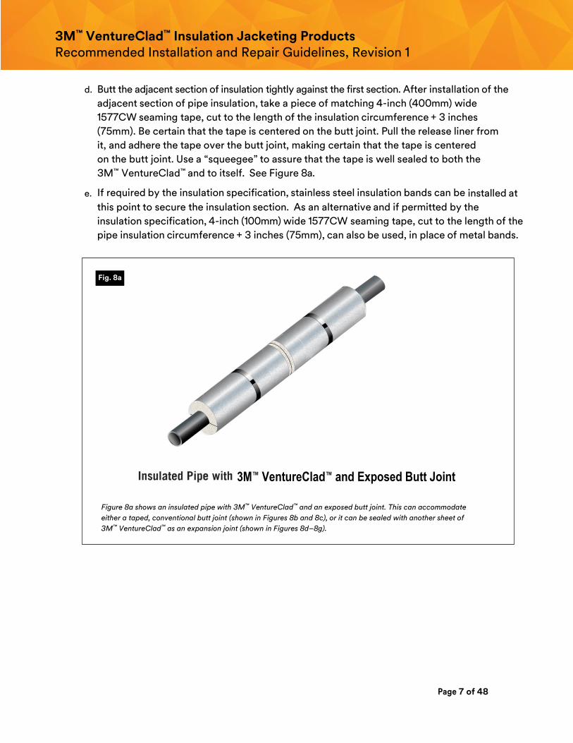
d. Butt the adjacent section of insulation tightly against the first section. After installation of the
adjacent section of pipe insulation, take a piece of matching 4-inch (400mm) wide
1577CW seaming tape, cut to the length of the insulation circumference + 3 inches
(75mm). Be certain that the tape is centered on the butt joint. Pull the release liner from
it, and adhere the tape over the butt joint, making certain that the tape is centered
on the butt joint. Use a “squeegee” to assure that the tape is well sealed to both the
3M™ VentureClad™ and to itself. See Figure 8a.
e. If required by the insulation specification, stainless steel insulation bands can be installed at
this point to secure the insulation section. As an alternative and if permitted by the
insulation specification, 4-inch (100mm) wide 1577CW seaming tape, cut to the length of the
pipe insulation circumference + 3 inches (75mm), can also be used, in place of metal bands.
Figure 8a shows an insulated pipe with 3M™ VentureClad™ and an exposed butt joint. This can accommodate
either a taped, conventional butt joint (shown in Figures 8b and 8c), or it can be sealed with another sheet of
3M™ VentureClad™ as an expansion joint (shown in Figures 8d–8g).
Fig. 8a
3M™ VentureClad™ and Exposed Butt Joint
Page 8 of 48
3M™ VentureClad™ Insulation Jacketing Products Recommended Installation and Repair Guidelines, Revision 1
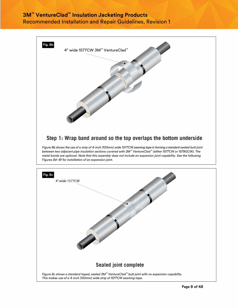
Figure 8b shows the use of a strip of 4-inch (100mm) wide 1577CW seaming tape in forming a standard sealed butt joint
between two adjacent pipe insulation sections covered with 3M™ VentureClad™ (either 1577CW or 1579GCW). The
metal bands are optional. Note that this assembly does not include an expansion joint capability. See the following
Figures 8d–8f for installation of an expansion joint.
Figure 8c shows a standard taped, sealed 3M™ VentureClad™ butt joint with no expansion capability. This makes use of a 4-inch (100mm) wide strip of 1577CW seaming tape.
Fig. 8b
Fig. 8c
4" wide 1577CW 3M™ VentureClad™
Page 9 of 48
3M™ VentureClad™ Insulation Jacketing Products Recommended Installation and Repair Guidelines, Revision 1
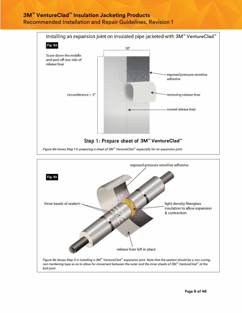
Figure 8d shows Step 1 in preparing a sheet of 3M™ VentureClad™ especially for an expansion joint.
Figure 8e shows Step 2 in installing a 3M™ VentureClad™ expansion joint. Note that the sealant should be a non-curing,
non-hardening type so as to allow for movement between the outer and the inner sheets of 3M™ VentureClad™ at the
butt joint.
Fig. 8d
Fig. 8e
3M™ VentureClad™
3M™ VentureClad™
Page 10 of 48
3M™ VentureClad™ Insulation Jacketing Products Recommended Installation and Repair Guidelines, Revision 1
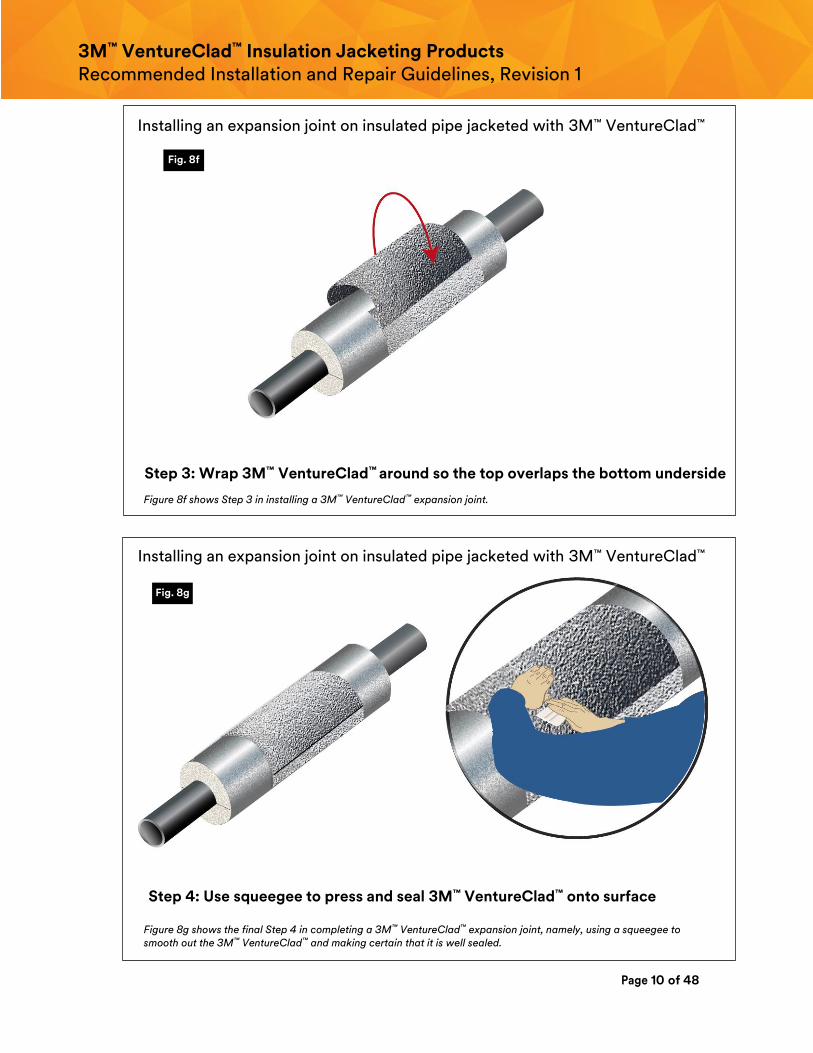
Figure 8f shows Step 3 in installing a 3M™ VentureClad™ expansion joint.
Figure 8g shows the final Step 4 in completing a 3M™ VentureClad™ expansion joint, namely, using a squeegee to smooth out the 3M™ VentureClad™ and making certain that it is well sealed.
Fig. 8f
Fig. 8g
Step 3: Wrap 3M™ VentureClad™ around so the top overlaps the bottom underside
Installing an expansion joint on insulated pipe jacketed with 3M™ VentureClad™
Step 4: Use squeegee to press and seal 3M™ VentureClad™ onto surface
Installing an expansion joint on insulated pipe jacketed with 3M™ VentureClad™
Page 11 of 48
3M™ VentureClad™ Insulation Jacketing Products Recommended Installation and Repair Guidelines, Revision 1
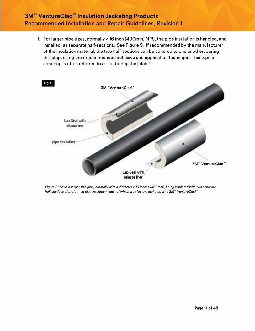
f. For larger pipe sizes, normally > 16 inch (400mm) NPS, the pipe insulation is handled, and
installed, as separate half‐sections. See Figure 9. If recommended by the manufacturer
of the insulation material, the two half‐sections can be adhered to one another, during
this step, using their recommended adhesive and application technique. This type of
adhering is often referred to as “buttering the joints”.
Figure 9 shows a larger size pipe, normally with a diameter > 16 inches (400mm), being insulated with two separate
half sections of preformed pipe insulation, each of which was factory jacketed with 3M™ VentureClad™.
Fig. 9
3M™ VentureClad™
3M™ VentureClad™
Page 12 of 48
3M™ VentureClad™ Insulation Jacketing Products Recommended Installation and Repair Guidelines, Revision 1
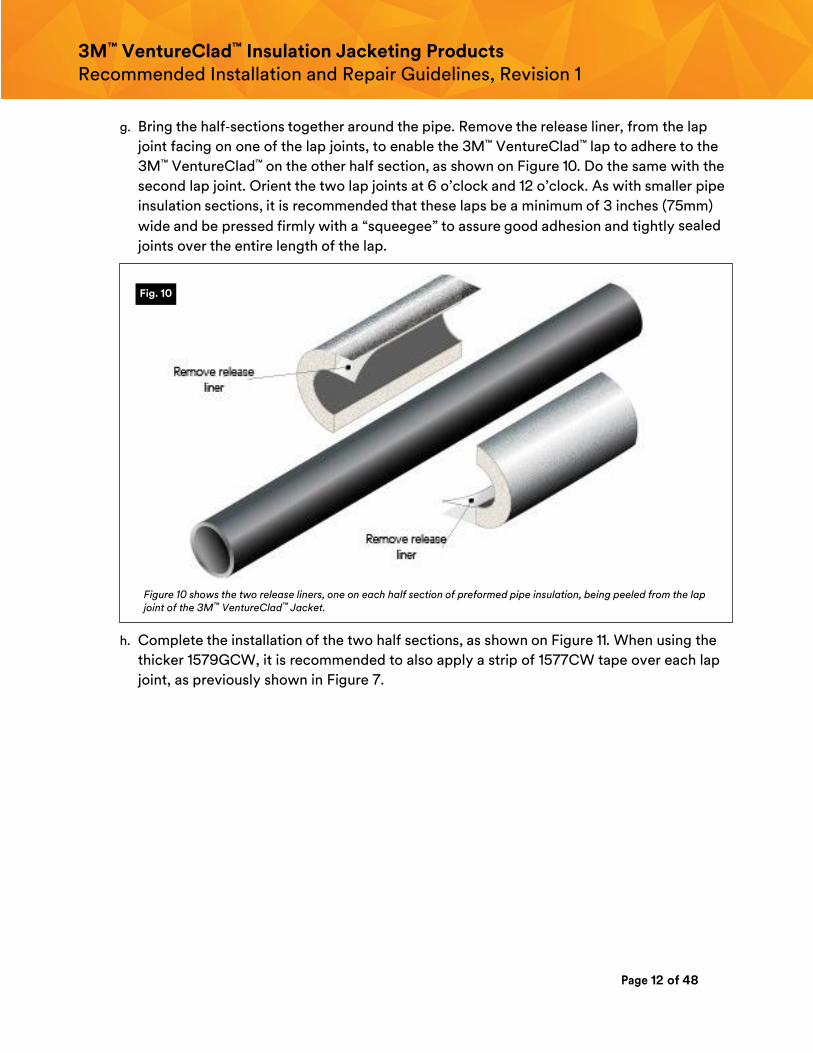
g. Bring the half‐sections together around the pipe. Remove the release liner, from the lap
joint facing on one of the lap joints, to enable the 3M™ VentureClad™ lap to adhere to the
3M™ VentureClad™ on the other half section, as shown on Figure 10. Do the same with the
second lap joint. Orient the two lap joints at 6 o’clock and 12 o’clock. As with smaller pipe
insulation sections, it is recommended that these laps be a minimum of 3 inches (75mm)
wide and be pressed firmly with a “squeegee” to assure good adhesion and tightly sealed
joints over the entire length of the lap.
Figure 10 shows the two release liners, one on each half section of preformed pipe insulation, being peeled from the lap joint of the 3M™ VentureClad™ Jacket.
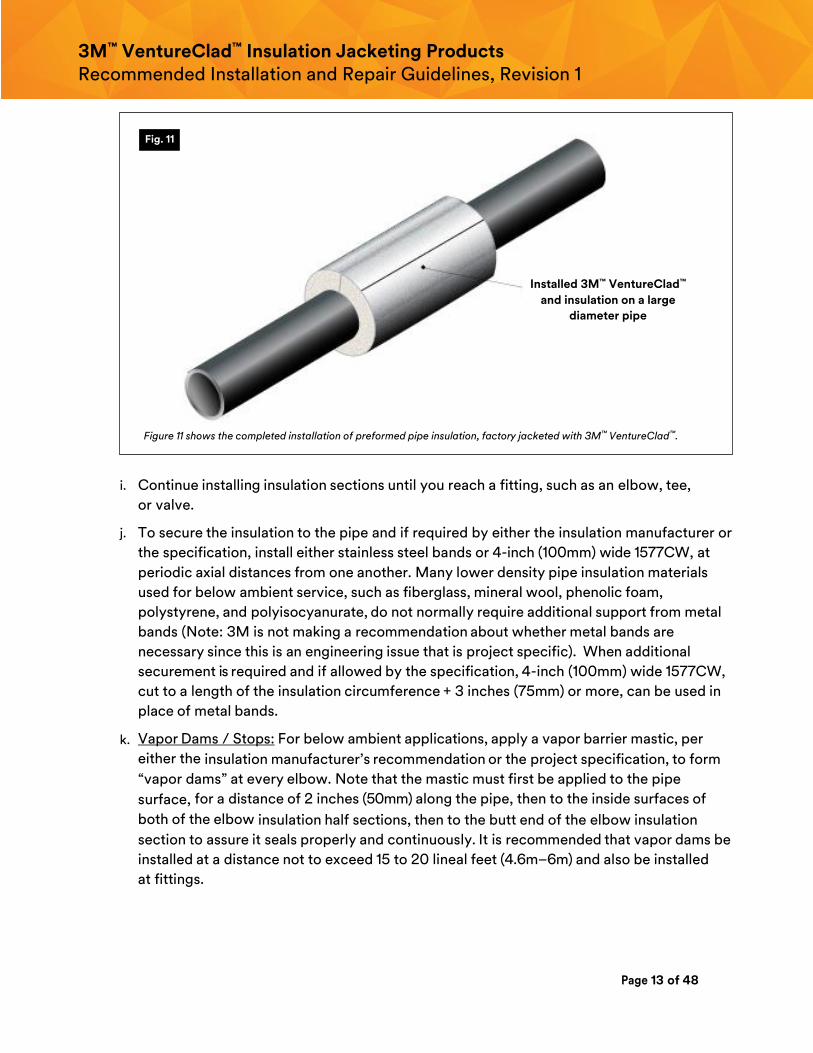
h. Complete the installation of the two half sections, as shown on Figure 11. When using the
thicker 1579GCW, it is recommended to also apply a strip of 1577CW tape over each lap
joint, as previously shown in Figure 7.
Fig. 10
Page 13 of 48
3M™ VentureClad™ Insulation Jacketing Products Recommended Installation and Repair Guidelines, Revision 1
Figure 11 shows the completed installation of preformed pipe insulation, factory jacketed with 3M™ VentureClad™.
i. Continue installing insulation sections until you reach a fitting, such as an elbow, tee,
or valve.
j. To secure the insulation to the pipe and if required by either the insulation manufacturer or
the specification, install either stainless steel bands or 4-inch (100mm) wide 1577CW, at
periodic axial distances from one another. Many lower density pipe insulation materials
used for below ambient service, such as fiberglass, mineral wool, phenolic foam,
polystyrene, and polyisocyanurate, do not normally require additional support from metal
bands (Note: 3M is not making a recommendation about whether metal bands are
necessary since this is an engineering issue that is project specific). When additional
securement is required and if allowed by the specification, 4-inch (100mm) wide 1577CW,
cut to a length of the insulation circumference + 3 inches (75mm) or more, can be used in
place of metal bands.
k. Vapor Dams / Stops: For below ambient applications, apply a vapor barrier mastic, per
either the insulation manufacturer’s recommendation or the project specification, to form
“vapor dams” at every elbow. Note that the mastic must first be applied to the pipe
surface, for a distance of 2 inches (50mm) along the pipe, then to the inside surfaces of
both of the elbow insulation half sections, then to the butt end of the elbow insulation
section to assure it seals properly and continuously. It is recommended that vapor dams be
installed at a distance not to exceed 15 to 20 lineal feet (4.6m–6m) and also be installed
at fittings.
Fig. 11
Installed 3M™ VentureClad™
and insulation on a large
diameter pipe
Page 14 of 48
3M™ VentureClad™ Insulation Jacketing Products Recommended Installation and Repair Guidelines, Revision 1
4. Field installation of 3M™ VentureClad™ jacket over insulated straight pipe:
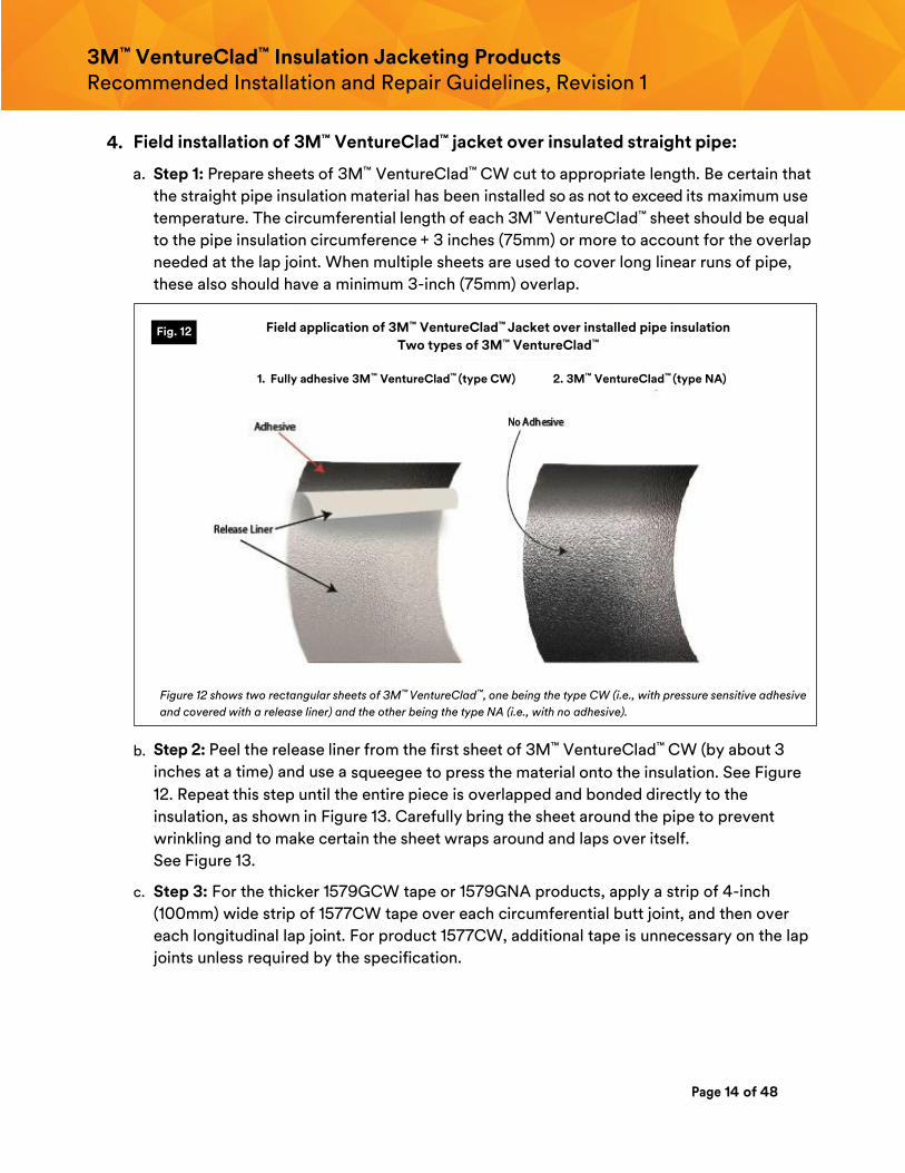
a. Step 1: Prepare sheets of 3M™ VentureClad™ CW cut to appropriate length. Be certain that
the straight pipe insulation material has been installed so as not to exceed its maximum use
temperature. The circumferential length of each 3M™ VentureClad™ sheet should be equal
to the pipe insulation circumference + 3 inches (75mm) or more to account for the overlap
needed at the lap joint. When multiple sheets are used to cover long linear runs of pipe,
these also should have a minimum 3-inch (75mm) overlap.
Figure 12 shows two rectangular sheets of 3M™ VentureClad™, one being the type CW (i.e., with pressure sensitive adhesive
and covered with a release liner) and the other being the type NA (i.e., with no adhesive).
b. Step 2: Peel the release liner from the first sheet of 3M™ VentureClad™ CW (by about 3
inches at a time) and use a squeegee to press the material onto the insulation. See Figure
12. Repeat this step until the entire piece is overlapped and bonded directly to the
insulation, as shown in Figure 13. Carefully bring the sheet around the pipe to prevent
wrinkling and to make certain the sheet wraps around and laps over itself.
See Figure 13.
c. Step 3: For the thicker 1579GCW tape or 1579GNA products, apply a strip of 4-inch
(100mm) wide strip of 1577CW tape over each circumferential butt joint, and then over
each longitudinal lap joint. For product 1577CW, additional tape is unnecessary on the lap
joints unless required by the specification.
Fig. 12 Field application of 3M™ VentureClad™ Jacket over installed pipe insulation
Two types of 3M™ VentureClad™
1. Fully adhesive 3M™ VentureClad™ (type CW) 2. 3M™ VentureClad™ (type NA)
Page 15 of 48
3M™ VentureClad™ Insulation Jacketing Products Recommended Installation and Repair Guidelines, Revision 1
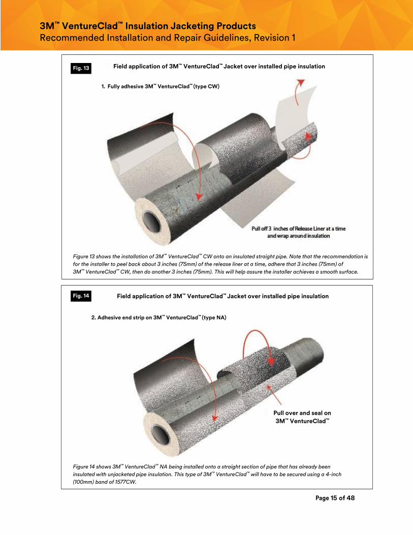
Figure 13 shows the installation of 3M™ VentureClad™ CW onto an insulated straight pipe. Note that the recommendation is
for the installer to peel back about 3 inches (75mm) of the release liner at a time, adhere that 3 inches (75mm) of
3M™ VentureClad™ CW, then do another 3 inches (75mm). This will help assure the installer achieves a smooth surface.
Figure 14 shows 3M™ VentureClad™ NA being installed onto a straight section of pipe that has already been
insulated with unjacketed pipe insulation. This type of 3M™ VentureClad™ will have to be secured using a 4-inch
(100mm) band of 1577CW.
Fig. 13
Fig. 14
1. Fully adhesive 3M™ VentureClad™ (type CW)
2. Adhesive end strip on 3M™ VentureClad™ (type NA)
Field application of 3M™ VentureClad™ Jacket over installed pipe insulation
Field application of 3M™ VentureClad™ Jacket over installed pipe insulation
Pull over and seal on
3M™ VentureClad™
Page 16 of 48
3M™ VentureClad™ Insulation Jacketing Products Recommended Installation and Repair Guidelines, Revision 1
d. Apply another sheet of 3M™ VentureClad™ in the same manner, adjacent to the first. The
sheets do not have to overlap one another, but should be within ½ inch (12mm) of one
another. Then, apply a strip of 4-inch (100mm) wide 1577CW to the circumferential joint.
On small bore pipe (i.e., < 4 ½ inch (115mm) NPS), it is recommended that 1579GNA be
used to cover the insulation and that a minimum 2-inch (50mm) wide 1577CW or 1578CW
be used on all longitudinal seams and mitered joints and that 4 inch (100mm) wide 1577CW
or 1578CW be used on all butt strip joints.
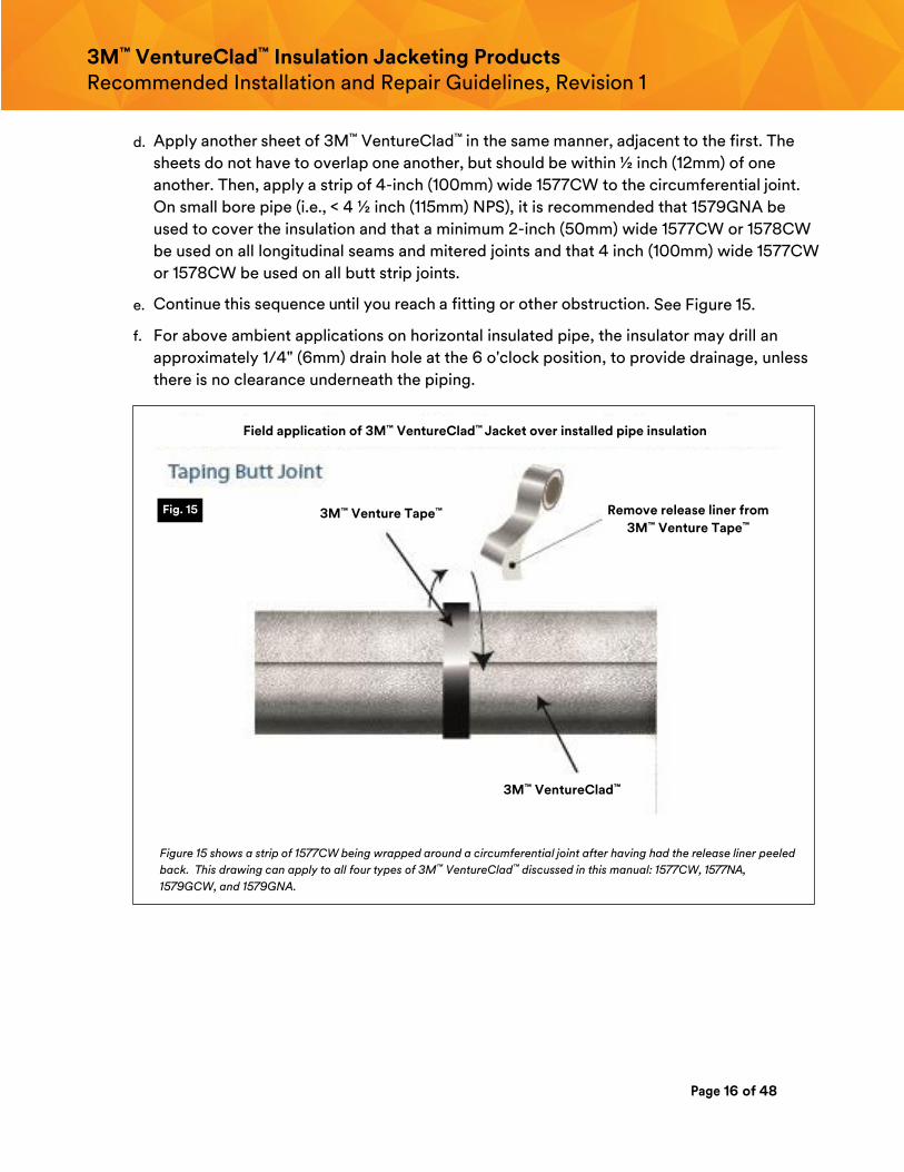
e. Continue this sequence until you reach a fitting or other obstruction. See Figure 15.
f. For above ambient applications on horizontal insulated pipe, the insulator may drill an
approximately 1/4" (6mm) drain hole at the 6 o'clock position, to provide drainage, unless
there is no clearance underneath the piping.
Figure 15 shows a strip of 1577CW being wrapped around a circumferential joint after having had the release liner peeled
back. This drawing can apply to all four types of 3M™ VentureClad™ discussed in this manual: 1577CW, 1577NA,
1579GCW, and 1579GNA.
Fig. 15
Field application of 3M™ VentureClad™ Jacket over installed pipe insulation
3M™ Venture Tape™ Remove release liner from
3M™ Venture Tape™
3M™ VentureClad™
Page 17 of 48
3M™ VentureClad™ Insulation Jacketing Products Recommended Installation and Repair Guidelines, Revision 1
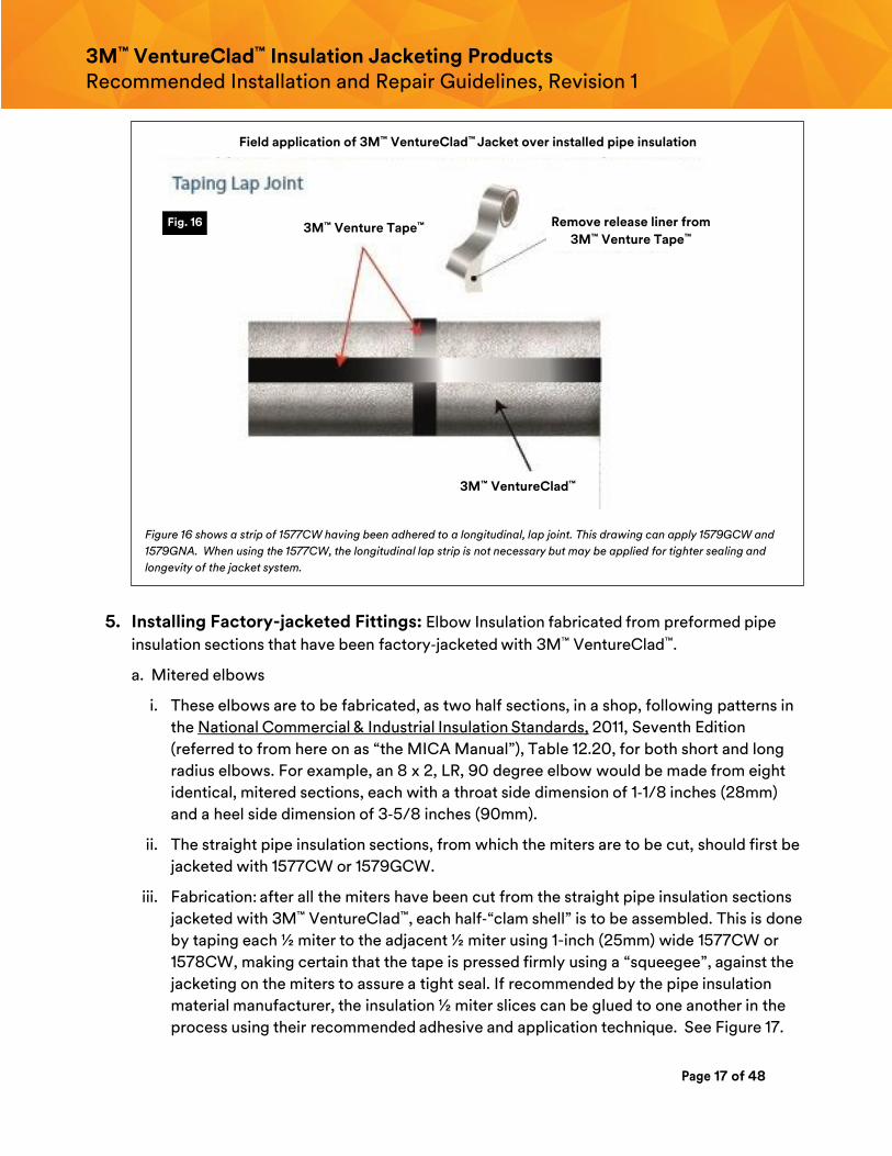
Figure 16 shows a strip of 1577CW having been adhered to a longitudinal, lap joint. This drawing can apply 1579GCW and
1579GNA. When using the 1577CW, the longitudinal lap strip is not necessary but may be applied for tighter sealing and
longevity of the jacket system.
5. Installing Factory-jacketed Fittings: Elbow Insulation fabricated from preformed pipe
insulation sections that have been factory‐jacketed with 3M™ VentureClad™.
a. Mitered elbows
i. These elbows are to be fabricated, as two half sections, in a shop, following patterns in
the National Commercial & Industrial Insulation Standards, 2011, Seventh Edition
(referred to from here on as “the MICA Manual”), Table 12.20, for both short and long
radius elbows. For example, an 8 x 2, LR, 90 degree elbow would be made from eight
identical, mitered sections, each with a throat side dimension of 1‐1/8 inches (28mm)
and a heel side dimension of 3‐5/8 inches (90mm).
ii. The straight pipe insulation sections, from which the miters are to be cut, should first be
jacketed with 1577CW or 1579GCW.
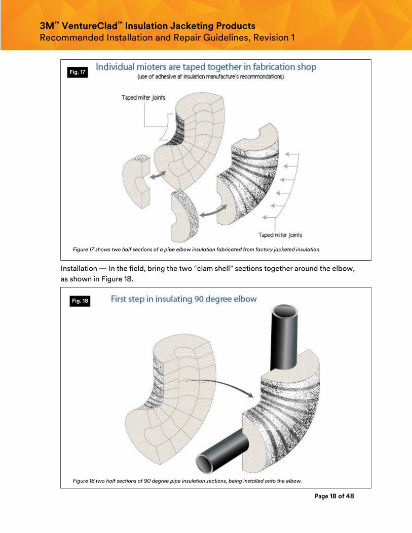
iii. Fabrication: after all the miters have been cut from the straight pipe insulation sections
jacketed with 3M™ VentureClad™, each half‐“clam shell” is to be assembled. This is done
by taping each ½ miter to the adjacent ½ miter using 1-inch (25mm) wide 1577CW or
1578CW, making certain that the tape is pressed firmly using a “squeegee”, against the
jacketing on the miters to assure a tight seal. If recommended by the pipe insulation
material manufacturer, the insulation ½ miter slices can be glued to one another in the
process using their recommended adhesive and application technique. See Figure 17.
Fig. 16 3M™ Venture Tape™ Remove release liner from
3M™ Venture Tape™
Field application of 3M™ VentureClad™ Jacket over installed pipe insulation
3M™ VentureClad™
Page 18 of 48
3M™ VentureClad™ Insulation Jacketing Products Recommended Installation and Repair Guidelines, Revision 1
Figure 17 shows two half sections of a pipe elbow insulation fabricated from factory jacketed insulation.
Installation — In the field, bring the two “clam shell” sections together around the elbow,
as shown in Figure 18.
Figure 18 two half sections of 90 degree pipe insulation sections, being installed onto the elbow.
Fig. 17
Fig. 18
Page 19 of 48
3M™ VentureClad™ Insulation Jacketing Products Recommended Installation and Repair Guidelines, Revision 1
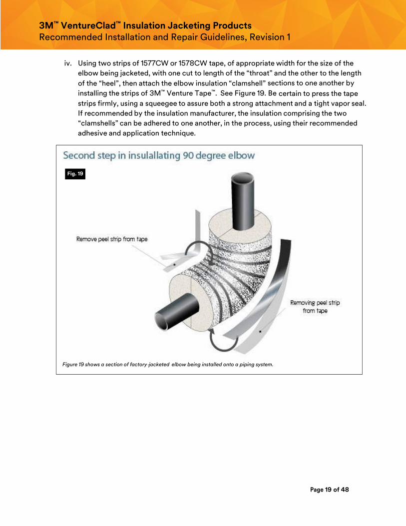
iv. Using two strips of 1577CW or 1578CW tape, of appropriate width for the size of the
elbow being jacketed, with one cut to length of the “throat” and the other to the length
of the “heel”, then attach the elbow insulation “clamshell” sections to one another by
installing the strips of 3M™ Venture Tape™. See Figure 19. Be certain to press the tape
strips firmly, using a squeegee to assure both a strong attachment and a tight vapor seal.
If recommended by the insulation manufacturer, the insulation comprising the two
“clamshells” can be adhered to one another, in the process, using their recommended
adhesive and application technique.
Figure 19 shows a section of factory‐jacketed elbow being installed onto a piping system.
Fig. 19
Page 20 of 48
3M™ VentureClad™ Insulation Jacketing Products Recommended Installation and Repair Guidelines, Revision 1
b. PVC jacketed elbow covers and other PVC fitting covers (generally for commercial
applications only)
i. For insulation systems using straight pipe sections factory jacketed with
3M™ VentureClad™ and with PCV elbows, follow either the PVC manufacturer’s
installation instructions or follow those in the MICA Manual (7th Edition, 2011), Plate No.
12. This is particularly important if the PVC fitting cover forms the vapor retarder for the
fitting. 3M is not making recommendations for how to seal the two PVC half sections to
one another since that should be provided by the PVC fitting cover manufacturer or by
the project specification.
ii. Some designers will not specify PVC jacketing for use outdoors and / or for high
temperature applications. Note that 3M is not recommending the use of PVC fitting
covers but merely acknowledging that they may be specified and used and if so, should
be attached and tightly sealed to the adjacent 3M™ VentureClad™ jacketed pipe
insulation.
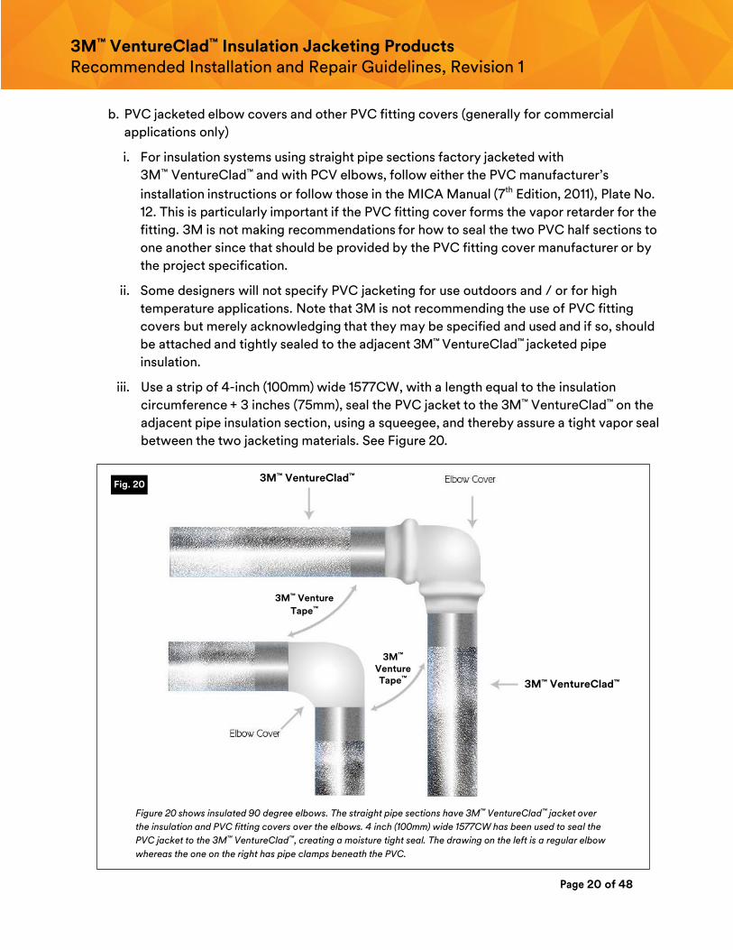
iii. Use a strip of 4-inch (100mm) wide 1577CW, with a length equal to the insulation
circumference + 3 inches (75mm), seal the PVC jacket to the 3M™ VentureClad™ on the
adjacent pipe insulation section, using a squeegee, and thereby assure a tight vapor seal
between the two jacketing materials. See Figure 20.
Figure 20 shows insulated 90 degree elbows. The straight pipe sections have 3M™ VentureClad™ jacket over
the insulation and PVC fitting covers over the elbows. 4 inch (100mm) wide 1577CW has been used to seal the
PVC jacket to the 3M™ VentureClad™, creating a moisture tight seal. The drawing on the left is a regular elbow
whereas the one on the right has pipe clamps beneath the PVC.
Fig. 20 3M™ VentureClad™
3M™ VentureClad™
3M™ Venture
Tape™
3M™ Venture Tape™
Page 21 of 48
3M™ VentureClad™ Insulation Jacketing Products Recommended Installation and Repair Guidelines, Revision 1
iv. It is recommended that other types of PVC fitting covers, such as those for Tees, be
sealed with 1577CW in the same manner as PVC elbows.
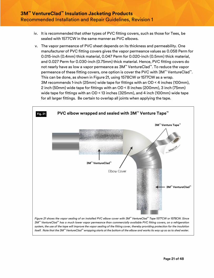
v. The vapor permeance of PVC sheet depends on its thickness and permeability. One
manufacturer of PVC fitting covers gives the vapor permeance values as 0.058 Perm for
0.015-inch (0.4mm) thick material, 0.047 Perm for 0.020-inch (0.5mm) thick material,
and 0.027 Perm for 0.030-inch (0.75mm) thick material. Hence, PVC fitting covers do
not nearly have as low a vapor permeance as 3M™ VentureClad™. To reduce the vapor
permeance of these fitting covers, one option is cover the PVC with 3M™ VentureClad™.
This can be done, as shown in Figure 21, using 1578CW or 1577CW as a wrap.
3M recommends 1-inch (25mm) wide tape for fittings with an OD < 4 inches (100mm),
2 inch (50mm) wide tape for fittings with an OD < 8 inches (200mm), 3 inch (75mm)
wide tape for fittings with an OD < 13 inches (325mm), and 4 inch (100mm) wide tape
for all larger fittings. Be certain to overlap all joints when applying the tape.
Figure 21 shows the vapor sealing of an installed PVC elbow cover with 3M™ VentureClad™ Tape 1577CW or 1578CW. Since
3M™ VentureClad™ has a much lower vapor permeance than commercially available PVC fitting covers, on a refrigeration
system, the use of the tape will improve the vapor sealing of the fitting cover, thereby providing protection for the insulation
itself. Note that the 3M™ VentureClad™ wrapping starts at the bottom of the elbow and works its way up so as to shed water.
Fig. 21
3M™ Venture Tape™
PVC elbow wrapped and sealed with 3M™ Venture Tape™
3M™ VentureClad™
3M™ VentureClad™
Page 22 of 48
3M™ VentureClad™ Insulation Jacketing Products Recommended Installation and Repair Guidelines, Revision 1
c. Pressed aluminum elbow covers and other aluminum fitting covers
i. For insulation systems using straight pipe sections factory jacketed with
3M™ VentureClad™ and with pressed aluminum elbows, follow the pressed aluminum
fitting cover manufacturer’s installation instructions.
ii. Note that 3M is not recommending the use of pressed elbow covers but merely
acknowledging that they may be specified or selected and if so, should be attached and
tightly sealed to the adjacent 3M™ VentureClad™ Jacketed Pipe Insulation.
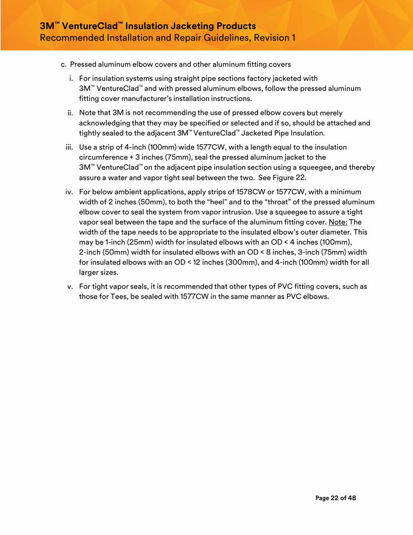
iii. Use a strip of 4-inch (100mm) wide 1577CW, with a length equal to the insulation
circumference + 3 inches (75mm), seal the pressed aluminum jacket to the
3M™ VentureClad™ on the adjacent pipe insulation section using a squeegee, and thereby
assure a water and vapor tight seal between the two. See Figure 22.
iv. For below ambient applications, apply strips of 1578CW or 1577CW, with a minimum
width of 2 inches (50mm), to both the “heel” and to the “throat” of the pressed aluminum
elbow cover to seal the system from vapor intrusion. Use a squeegee to assure a tight
vapor seal between the tape and the surface of the aluminum fitting cover. Note: The
width of the tape needs to be appropriate to the insulated elbow’s outer diameter. This
may be 1-inch (25mm) width for insulated elbows with an OD < 4 inches (100mm),
2-inch (50mm) width for insulated elbows with an OD < 8 inches, 3-inch (75mm) width
for insulated elbows with an OD < 12 inches (300mm), and 4-inch (100mm) width for all
larger sizes.
v. For tight vapor seals, it is recommended that other types of PVC fitting covers, such as
those for Tees, be sealed with 1577CW in the same manner as PVC elbows.
Page 23 of 48
3M™ VentureClad™ Insulation Jacketing Products Recommended Installation and Repair Guidelines, Revision 1
Figure 22 shows a method for using 1577CW to seal an aluminum elbow cover to the straight pipe insulation that has
pre‐jacketed with 3M™ VentureClad™. This same approach can be used to seal an aluminum fitting cover to
aluminum pipe jacket. Note the application of 3M™ VentureClad™ to the aluminum fitting cover seams to seal it for
below ambient applications.
vi. Vapor Dams / Stops: See Section 2.L.
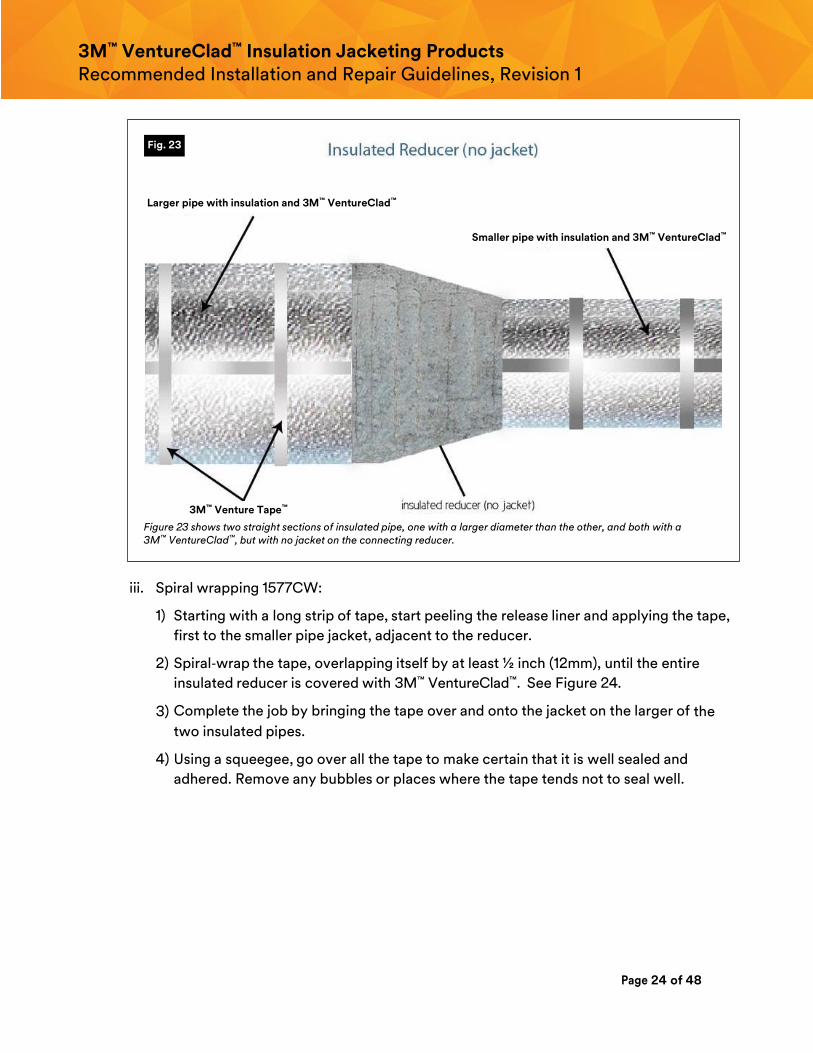
e. Insulated Reducer
i. Insulated pipe reducers can be jacketed using one of two methods: either 4-inch
(100mm) wide 1577CW, spiral wrapped around the reducer, or with a piece of
3M™ VentureClad™ pre‐cut from a larger sheet of 1579GNA.
ii. The adjacent two sections of straight pipe should already have been insulated and
jacketed with 3M™ VentureClad™. See Figure 23.
Fig. 22 3M™ VentureClad™ 3M™ Venture Tape™ 3M™ Venture Tape™
on seams (for below ambient applications)
3M™ Venture Tape™
3M™ VentureClad™
3M™ Venture Tape™ on seams (for below
ambient applications)
Page 24 of 48
3M™ VentureClad™ Insulation Jacketing Products Recommended Installation and Repair Guidelines, Revision 1
Figure 23 shows two straight sections of insulated pipe, one with a larger diameter than the other, and both with a 3M™ VentureClad™, but with no jacket on the connecting reducer.
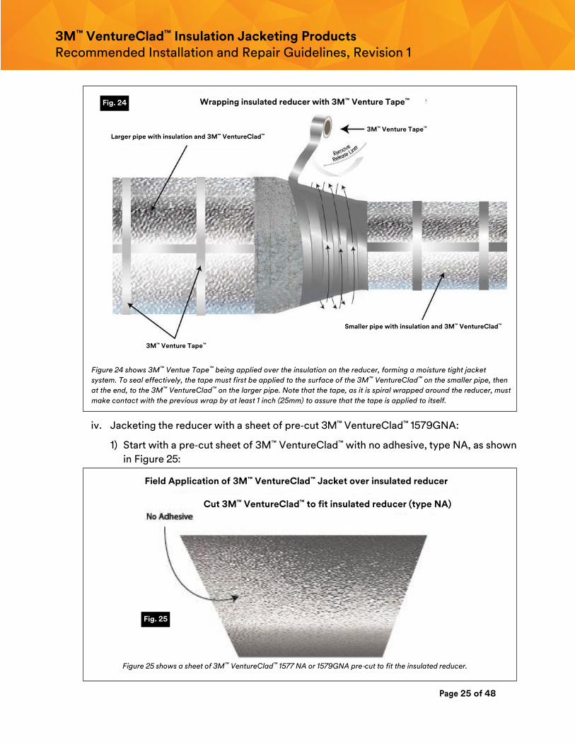
iii. Spiral wrapping 1577CW:
1) Starting with a long strip of tape, start peeling the release liner and applying the tape,
first to the smaller pipe jacket, adjacent to the reducer.
2) Spiral‐wrap the tape, overlapping itself by at least ½ inch (12mm), until the entire
insulated reducer is covered with 3M™ VentureClad™. See Figure 24.
3) Complete the job by bringing the tape over and onto the jacket on the larger of the
two insulated pipes.
4) Using a squeegee, go over all the tape to make certain that it is well sealed and
adhered. Remove any bubbles or places where the tape tends not to seal well.
Fig. 23
Larger pipe with insulation and 3M™ VentureClad™
Smaller pipe with insulation and 3M™ VentureClad™
3M™ Venture Tape™
Page 25 of 48
3M™ VentureClad™ Insulation Jacketing Products Recommended Installation and Repair Guidelines, Revision 1
Figure 24 shows 3M™ Ventue Tape™ being applied over the insulation on the reducer, forming a moisture tight jacket
system. To seal effectively, the tape must first be applied to the surface of the 3M™ VentureClad™ on the smaller pipe, then
at the end, to the 3M™ VentureClad™ on the larger pipe. Note that the tape, as it is spiral wrapped around the reducer, must
make contact with the previous wrap by at least 1 inch (25mm) to assure that the tape is applied to itself.
iv. Jacketing the reducer with a sheet of pre‐cut 3M™ VentureClad™ 1579GNA:
1) Start with a pre‐cut sheet of 3M™ VentureClad™ with no adhesive, type NA, as shown
in Figure 25:
Figure 25 shows a sheet of 3M™ VentureClad™ 1577 NA or 1579GNA pre‐cut to fit the insulated reducer.
Fig. 24
Fig. 25
3M™ Venture Tape™
Wrapping insulated reducer with 3M™ Venture Tape™
Larger pipe with insulation and 3M™ VentureClad™
3M™ Venture Tape™
Smaller pipe with insulation and 3M™ VentureClad™
Field Application of 3M™ VentureClad™ Jacket over insulated reducer
Cut 3M™ VentureClad™ to fit insulated reducer (type NA)
Page 26 of 48
3M™ VentureClad™ Insulation Jacketing Products Recommended Installation and Repair Guidelines, Revision 1
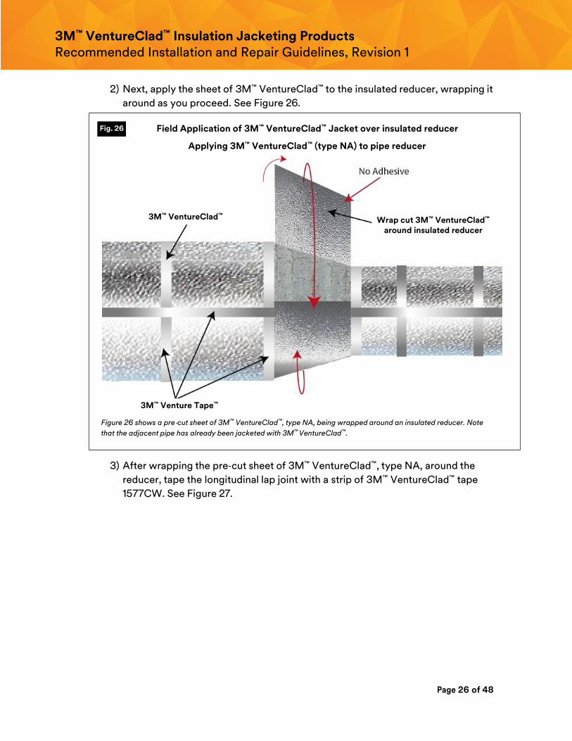
2) Next, apply the sheet of 3M™ VentureClad™ to the insulated reducer, wrapping it
around as you proceed. See Figure 26.
Figure 26 shows a pre‐cut sheet of 3M™ VentureClad™, type NA, being wrapped around an insulated reducer. Note
that the adjacent pipe has already been jacketed with 3M™ VentureClad™.
3) After wrapping the pre‐cut sheet of 3M™ VentureClad™, type NA, around the
reducer, tape the longitudinal lap joint with a strip of 3M™ VentureClad™ tape
1577CW. See Figure 27.
Fig. 26 Field Application of 3M™ VentureClad™ Jacket over insulated reducer
Applying 3M™ VentureClad™ (type NA) to pipe reducer
3M™ VentureClad™ Wrap cut 3M™ VentureClad™ around insulated reducer
3M™ Venture Tape™
Page 27 of 48
3M™ VentureClad™ Insulation Jacketing Products Recommended Installation and Repair Guidelines, Revision 1
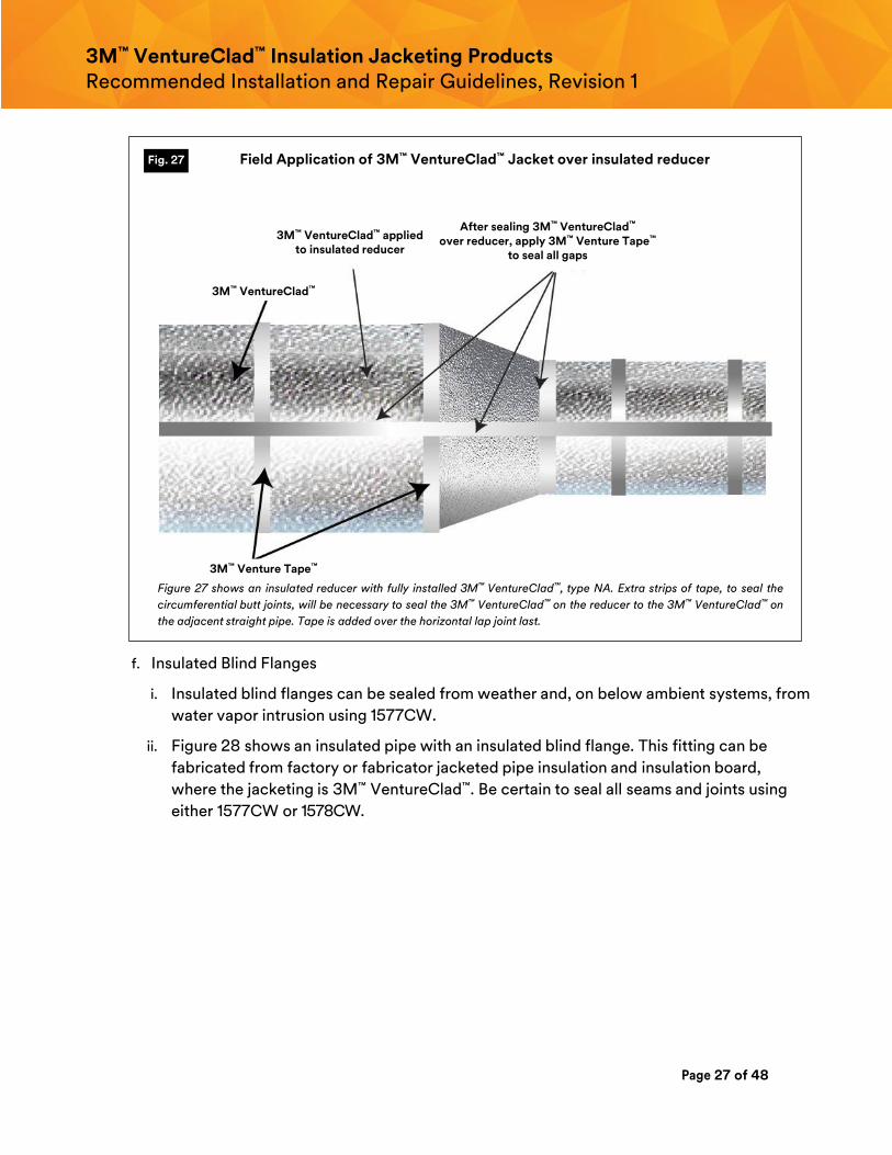
Figure 27 shows an insulated reducer with fully installed 3M™ VentureClad™, type NA. Extra strips of tape, to seal the
circumferential butt joints, will be necessary to seal the 3M™ VentureClad™ on the reducer to the 3M™ VentureClad™ on
the adjacent straight pipe. Tape is added over the horizontal lap joint last.
f. Insulated Blind Flanges
i. Insulated blind flanges can be sealed from weather and, on below ambient systems, from
water vapor intrusion using 1577CW.
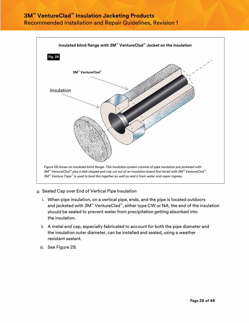
ii. Figure 28 shows an insulated pipe with an insulated blind flange. This fitting can be
fabricated from factory or fabricator jacketed pipe insulation and insulation board,
where the jacketing is 3M™ VentureClad™. Be certain to seal all seams and joints using
either 1577CW or 1578CW.
Fig. 27 Field Application of 3M™ VentureClad™ Jacket over insulated reducer
3M™ VentureClad™ applied to insulated reducer
After sealing 3M™ VentureClad™ over reducer, apply 3M™ Venture Tape™
to seal all gaps
3M™ VentureClad™
3M™ Venture Tape™
Page 28 of 48
3M™ VentureClad™ Insulation Jacketing Products Recommended Installation and Repair Guidelines, Revision 1
Figure 28 shows an insulated blind flange. This insulation system consists of pipe insulation pre‐jacketed with
3M™ VentureClad™ plus a disk shaped end cap cut out of an insulation board first faced with 3M™ VentureClad™.
3M™ Venture Tape™ is used to bind this together as well as seal it from water and vapor ingress.
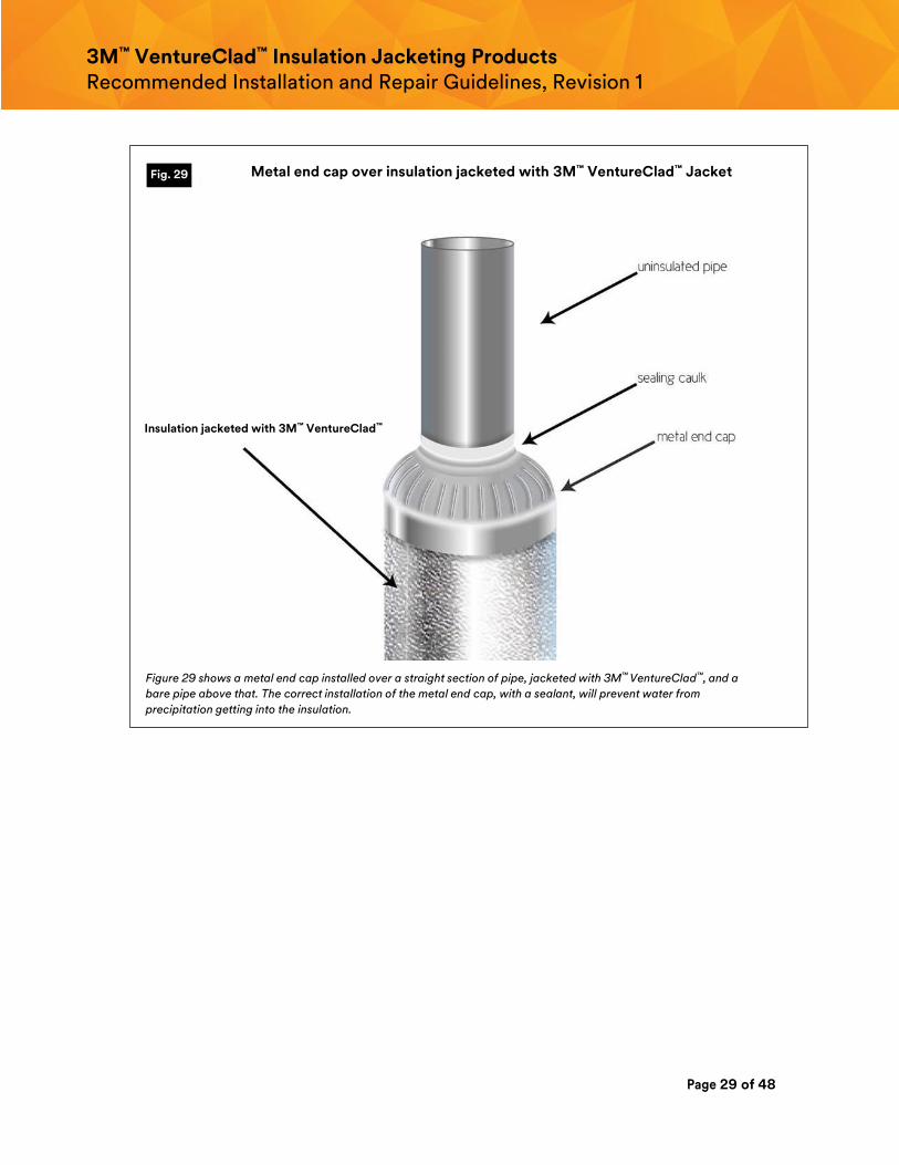
g. Sealed Cap over End of Vertical Pipe Insulation
i. When pipe insulation, on a vertical pipe, ends, and the pipe is located outdoors
and jacketed with 3M™ VentureClad™, either type CW or NA, the end of the insulation
should be sealed to prevent water from precipitation getting absorbed into
the insulation.
ii. A metal end cap, especially fabricated to account for both the pipe diameter and
the insulation outer diameter, can be installed and sealed, using a weather
resistant sealant.
iii. See Figure 29.
Fig. 28
3M™ VentureClad™
Insulated blind flange with 3M™ VentureClad™ Jacket on the insulation
Page 29 of 48
3M™ VentureClad™ Insulation Jacketing Products Recommended Installation and Repair Guidelines, Revision 1
Figure 29 shows a metal end cap installed over a straight section of pipe, jacketed with 3M™ VentureClad™, and a
bare pipe above that. The correct installation of the metal end cap, with a sealant, will prevent water from
precipitation getting into the insulation.
Fig. 29 Metal end cap over insulation jacketed with 3M™ VentureClad™ Jacket
Insulation jacketed with 3M™ VentureClad™
Page 30 of 48
3M™ VentureClad™ Insulation Jacketing Products Recommended Installation and Repair Guidelines, Revision 1
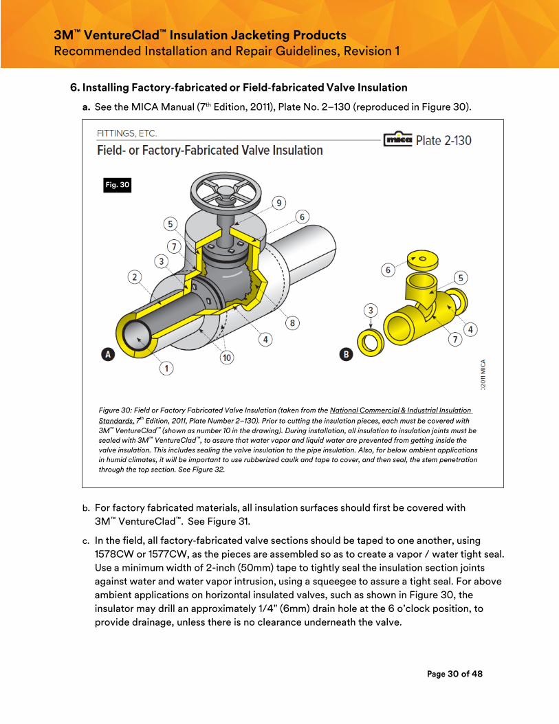
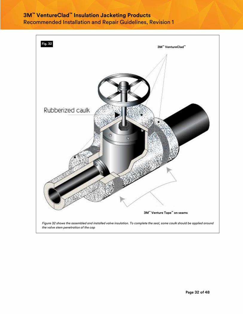
6. Installing Factory‐fabricated or Field‐fabricated Valve Insulation
a. See the MICA Manual (7th Edition, 2011), Plate No. 2–130 (reproduced in Figure 30).
Figure 30: Field or Factory Fabricated Valve Insulation (taken from the National Commercial & Industrial Insulation
Standards, 7th Edition, 2011, Plate Number 2–130). Prior to cutting the insulation pieces, each must be covered with
3M™ VentureClad™ (shown as number 10 in the drawing). During installation, all insulation to insulation joints must be
sealed with 3M™ VentureClad™, to assure that water vapor and liquid water are prevented from getting inside the
valve insulation. This includes sealing the valve insulation to the pipe insulation. Also, for below ambient applications
in humid climates, it will be important to use rubberized caulk and tape to cover, and then seal, the stem penetration
through the top section. See Figure 32.
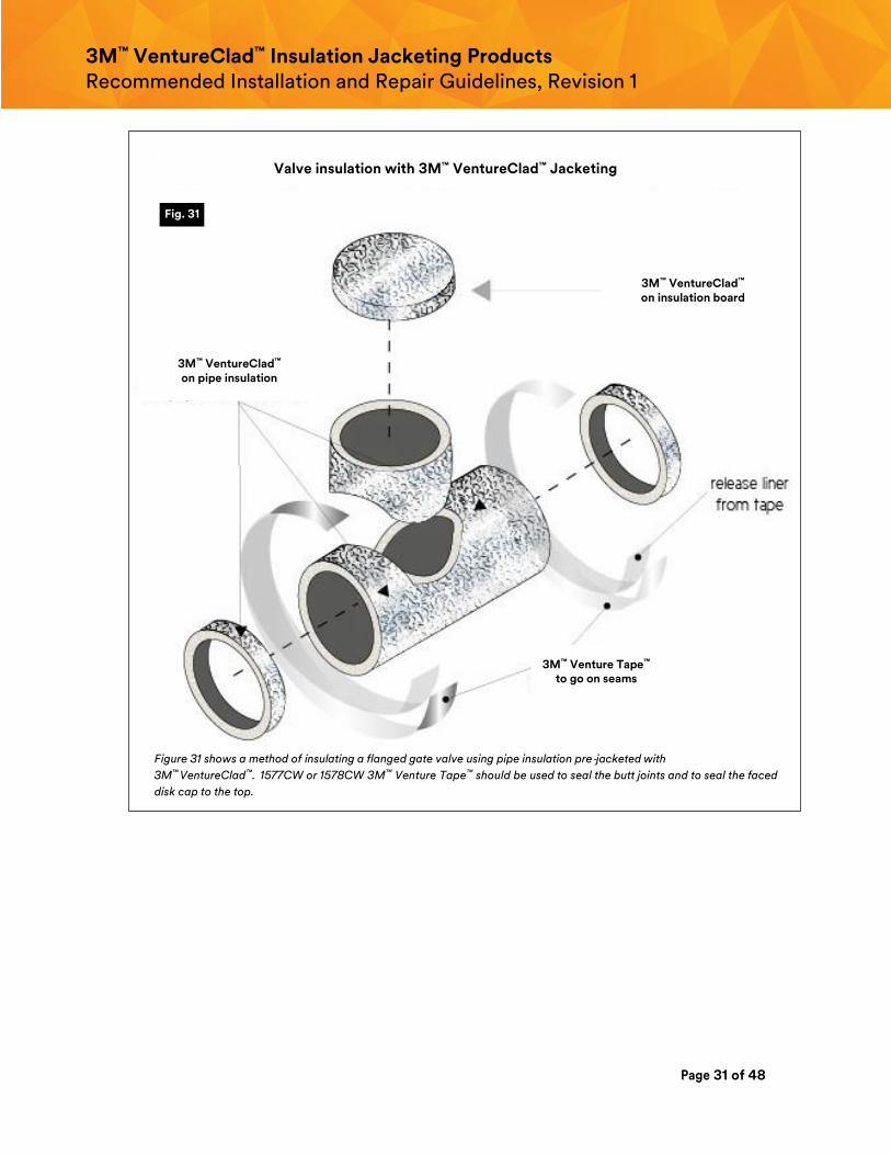
b. For factory fabricated materials, all insulation surfaces should first be covered with
3M™ VentureClad™. See Figure 31.
c. In the field, all factory‐fabricated valve sections should be taped to one another, using
1578CW or 1577CW, as the pieces are assembled so as to create a vapor / water tight seal.
Use a minimum width of 2-inch (50mm) tape to tightly seal the insulation section joints
against water and water vapor intrusion, using a squeegee to assure a tight seal. For above
ambient applications on horizontal insulated valves, such as shown in Figure 30, the
insulator may drill an approximately 1/4" (6mm) drain hole at the 6 o’clock position, to
provide drainage, unless there is no clearance underneath the valve.
Fig. 30
Page 31 of 48
3M™ VentureClad™ Insulation Jacketing Products Recommended Installation and Repair Guidelines, Revision 1
Figure 31 shows a method of insulating a flanged gate valve using pipe insulation pre‐jacketed with
3M™ VentureClad™. 1577CW or 1578CW 3M™ Venture Tape™ should be used to seal the butt joints and to seal the faced
disk cap to the top.
Fig. 31
Valve insulation with 3M™ VentureClad™ Jacketing
3M™ VentureClad™ on insulation board
3M™ VentureClad™ on pipe insulation
Valve insulation with 3M™ VentureClad™ Jacketing
3M™ Venture Tape™ to go on seams
Page 32 of 48
3M™ VentureClad™ Insulation Jacketing Products Recommended Installation and Repair Guidelines, Revision 1
Figure 32 shows the assembled and installed valve insulation. To complete the seal, some caulk should be applied around
the valve stem penetration of the cap
Fig. 32 3M™ VentureClad™
3M™ Venture Tape™ on seams
Page 33 of 48
3M™ VentureClad™ Insulation Jacketing Products Recommended Installation and Repair Guidelines, Revision 1
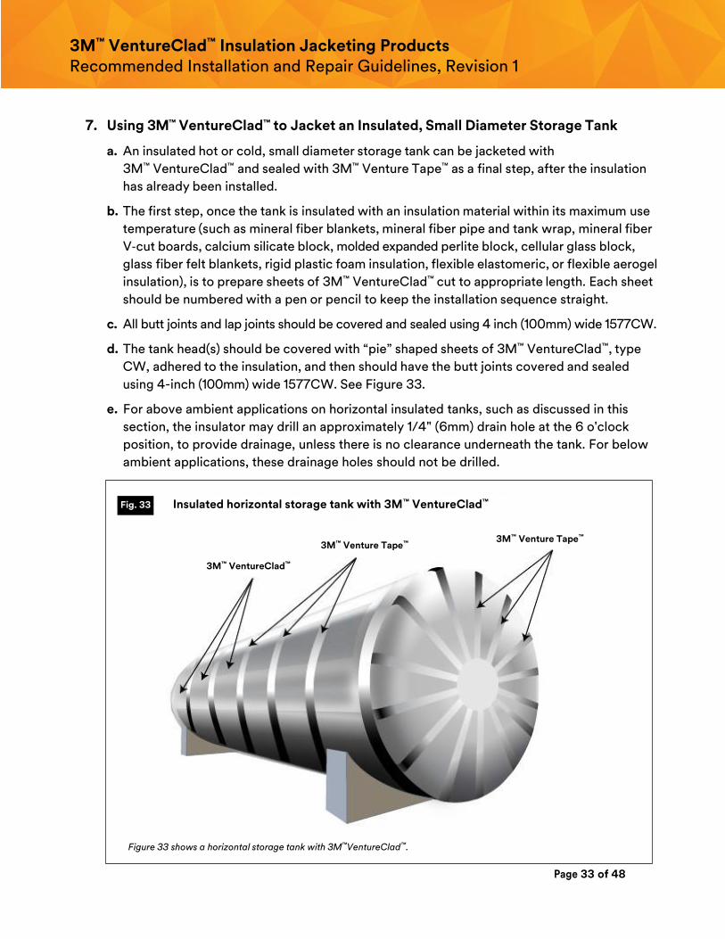
7. Using 3M™ VentureClad™ to Jacket an Insulated, Small Diameter Storage Tank
a. An insulated hot or cold, small diameter storage tank can be jacketed with
3M™ VentureClad™ and sealed with 3M™ Venture Tape™ as a final step, after the insulation
has already been installed.
b. The first step, once the tank is insulated with an insulation material within its maximum use
temperature (such as mineral fiber blankets, mineral fiber pipe and tank wrap, mineral fiber
V‐cut boards, calcium silicate block, molded expanded perlite block, cellular glass block,
glass fiber felt blankets, rigid plastic foam insulation, flexible elastomeric, or flexible aerogel
insulation), is to prepare sheets of 3M™ VentureClad™ cut to appropriate length. Each sheet
should be numbered with a pen or pencil to keep the installation sequence straight.
c. All butt joints and lap joints should be covered and sealed using 4 inch (100mm) wide 1577CW.
d. The tank head(s) should be covered with “pie” shaped sheets of 3M™ VentureClad™, type
CW, adhered to the insulation, and then should have the butt joints covered and sealed
using 4-inch (100mm) wide 1577CW. See Figure 33.
e. For above ambient applications on horizontal insulated tanks, such as discussed in this
section, the insulator may drill an approximately 1/4" (6mm) drain hole at the 6 o'clock
position, to provide drainage, unless there is no clearance underneath the tank. For below
ambient applications, these drainage holes should not be drilled.
Figure 33 shows a horizontal storage tank with 3M™VentureClad™.
Fig. 33
3M™ VentureClad™
3M™ Venture Tape™ 3M™ Venture Tape™
Insulated horizontal storage tank with 3M™ VentureClad™
Page 34 of 48
3M™ VentureClad™ Insulation Jacketing Products Recommended Installation and Repair Guidelines, Revision 1
8. Using Insulation boards, factory jacketed with 3M™ VentureClad™, to insulate a
Large Diameter Horizontal Storage Tank operating at temperatures from ambient
up to 350°F.
As an alternative, the tank can first be insulated and covered with 3M™ VentureClad™, type
CW, field installed. However, the steps below apply to factory jacketed insulation either on
flexible insulation blankets or on rigid insulation boards.
a. A hot tank operating at a temperature up to 350°F can be insulated with insulation boards
that have been factory‐jacketed, or faced, with 1577CW or 1579GCW. Seams can be
sealed using 1577CW tape.
b. The insulation should first be applied to the sidewalls, then to the roof.
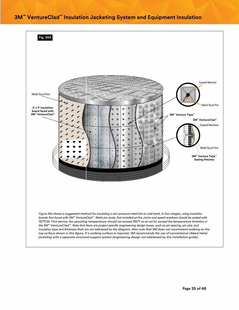
c. As shown on Figure 34, the first step is to install weld stud pins on the tank surfaces. The
spacing and size (i.e., diameter) of these weld stud pins must first be determined by an
engineering analysis that takes into account design wind loads and insulation weight. The
length of the pins after cutting off extra length, would be only 1/16 inch (2mm) longer than
the insulation type and thickness which also must be determined by engineering analysis
that takes into account maximum allowable heat loss, or heat gain, for design conditions.
d. The second step is to push each 2-foot x 4 foot insulation board, faced with
3M™ VentureClad™, over the weld stud pins. Each board must butt up against the
adjacent board.
e. The third step is to push speed washers over the weld stud pins. These are pressed
down to the surface of the insulation board sufficiently to slightly depress the board.
f. The forth step is to tape all the joints with the 1577CW, that has a minimum width of
4 inches (100mm), using a squeegee to make certain that the tape adheres completely to
the boards.
g. The fifth step is to bend the protruding end of each weld stud pin 90° so it is flush with
the speed washer.
h. The sixth step is to cover and seal each speed washer / weld pin stud with a piece of
3M™ VentureClad™ that is sufficiently long to cover the washer.
i. The roof can be insulated in the same manner as the sidewalls. 3M™ VentureClad™ should
be used to seal the roof insulation system to the sidewall insulation system.
j. Blanket Insulation: Rolls of blanket insulation, such as fiberglass, mineral wool, glass fiber
mat, and aerogel, can also be used to insulate tanks. Unfaced rolls of blanket insulation
would first be applied over weld pin studs to the tank’s surfaces. Then, 3M™ VentureClad™
would be applied over top of that, also working with rolls, and this would be sealed with
1577CW. As with the insulation boards, there are many engineering issues that must be
suitably addressed by others.
k. Repairs to rips and tears in the 3M™ VentureClad™ Jacket would be made in the same
manner as shown for pipe insulation (shown at the end of this manual).
Page 35 of 48
3M™ VentureClad™ Insulation Jacketing System and Equipment Insulation
Figure 34a shows a suggested method for insulating a non-pressure rated hot or cold tank, in four stages, using insulation
boards first faced with 3M™ VentureClad™. Weld-pin studs, first installed on the Joints and speed washers should be sealed with
1577CW. If hot service, the operating temperature should not exceed 350°F so as not to exceed the temperature limitation of
the 3M™ VentureClad™. Note that there are project specific engineering design issues, such as pin spacing, pin size, and
insulation type and thickness that are not addressed by this diagram. Also note that 3M does not recommend walking on the
top surface shown in this figure. If a walking surface is required, 3M recommends the use of conventional ribbed metal
jacketing with a separate structural support system (engineering design not addressed by this installation guide).
Fig. 34A
' ' '
' ' '
' ' '
' ' '
' ' ' ' ' ' '' '
3M™ Venture Tape™
3M™ Venture Tape™
Sealing Patches
3M™ VentureClad™
2' x 4' insulation board faced with
3M™ VentureClad™
Page 36 of 48
3M™ VentureClad™ Insulation Jacketing System and Equipment Insulation
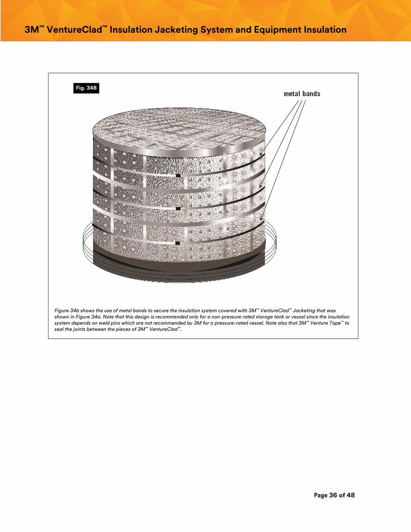
Figure 34b shows the use of metal bands to secure the insulation system covered with 3M™ VentureClad™ Jacketing that was shown in Figure 34a. Note that this design is recommended only for a non-pressure rated storage tank or vessel since the insulation system depends on weld pins which are not recommended by 3M for a pressure-rated vessel. Note also that 3M™ Venture Tape™ to seal the joints between the pieces of 3M™ VentureClad™.
Fig. 34B
Page 37 of 48
3M™ VentureClad™ Insulation Jacketing System and Equipment Insulation
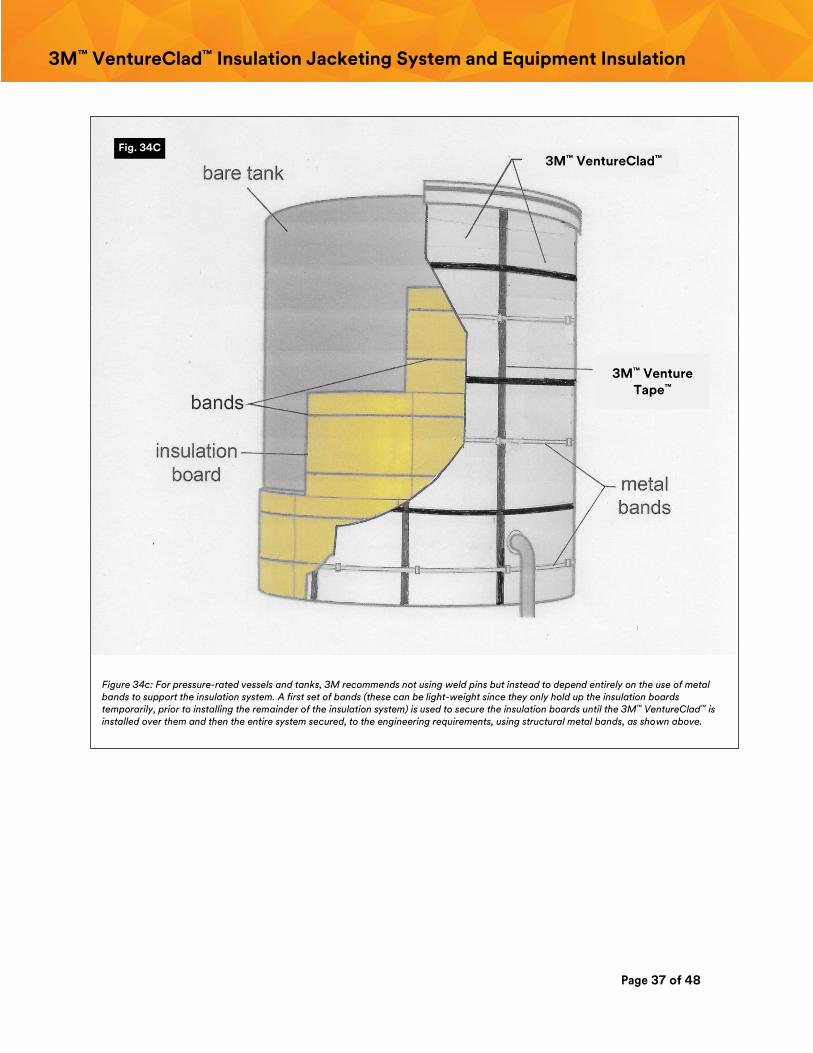
Figure 34c: For pressure-rated vessels and tanks, 3M recommends not using weld pins but instead to depend entirely on the use of metal bands to support the insulation system. A first set of bands (these can be light-weight since they only hold up the insulation boards temporarily, prior to installing the remainder of the insulation system) is used to secure the insulation boards until the 3M™ VentureClad™ is installed over them and then the entire system secured, to the engineering requirements, using structural metal bands, as shown above.
Fig. 34C
3M™ VentureClad™
3M™ Venture Tape™
Page 38 of 48
3M™ VentureClad™ Insulation Jacketing System and Equipment Insulation
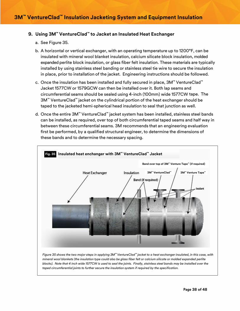
9. Using 3M™ VentureClad™ to Jacket an Insulated Heat Exchanger
a. See Figure 35.
b. A horizontal or vertical exchanger, with an operating temperature up to 1200°F, can be
insulated with mineral wool blanket insulation, calcium silicate block insulation, molded
expanded perlite block insulation, or glass fiber felt insulation. These materials are typically
installed by using stainless steel banding or stainless steel tie wire to secure the insulation
in place, prior to installation of the jacket. Engineering instructions should be followed.
c. Once the insulation has been installed and fully secured in place, 3M™ VentureClad™
Jacket 1577CW or 1579GCW can then be installed over it. Both lap seams and
circumferential seams should be sealed using 4-inch (100mm) wide 1577CW tape. The
3M™ VentureClad™ jacket on the cylindrical portion of the heat exchanger should be
taped to the jacketed hemi‐spherical head insulation to seal that junction as well.
d. Once the entire 3M™ VentureClad™ jacket system has been installed, stainless steel bands
can be installed, as required, over top of both circumferential taped seams and half way in
between these circumferential seams. 3M recommends that an engineering evaluation
first be performed, by a qualified structural engineer, to determine the dimensions of
these bands and to determine the necessary spacing.
Figure 35 shows the two major steps in applying 3M™ VentureClad™ jacket to a heat exchanger insulated, in this case, with
mineral wool blankets (the insulation type could also be glass fiber felt or calcium silicate or molded expanded perlite
blocks). Note that 4 inch wide 1577CW is used to seal the joints. Finally, stainless steel bands may be installed over the
taped circumferential joints to further secure the insulation system if required by the specification.
Fig. 35 Insulated heat enchanger with 3M™ VentureClad™ Jacket
3M™ VentureClad™ 3M™ Venture Tape™
Band over top of 3M™ Venture Tape™ (if required)
Page 39 of 48
3M™ VentureClad™ Insulation Jacketing System and Equipment Insulation
10. Repair of punctures and tears of the 3M™ VentureClad™
a. While both 3M™ VentureClad™ 1577CW and 1579GCW are strong and resistant to rips,
punctures and / or tears, any of these types of damage can occur with enough pressure.
When this happens, the damage should be repaired as soon as possible, particularly on
below ambient applications.
b. To make a repair, clean the area around the rip, puncture, or tear with a cloth to remove
dust and lose dirt. If an oily substance is on the 3M™ VentureClad™ surface, it should first be
removed with an appropriate solvent, as recommended by either the specification or the
facility owner.
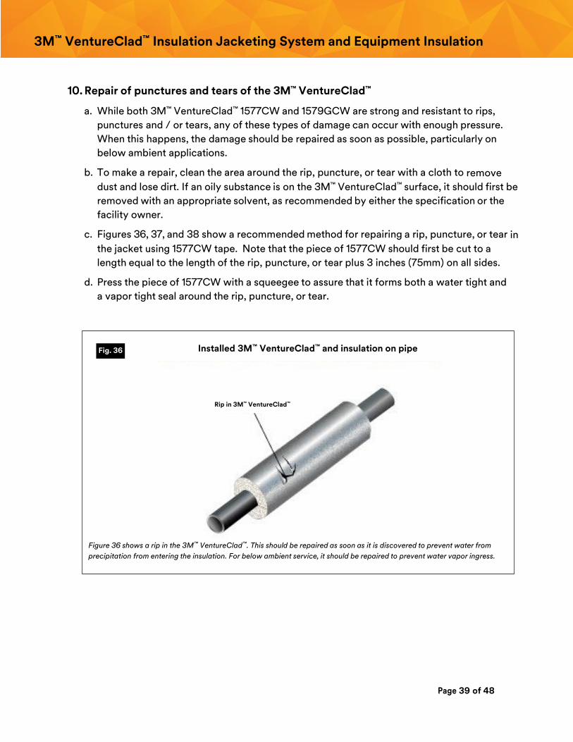
c. Figures 36, 37, and 38 show a recommended method for repairing a rip, puncture, or tear in
the jacket using 1577CW tape. Note that the piece of 1577CW should first be cut to a
length equal to the length of the rip, puncture, or tear plus 3 inches (75mm) on all sides.
d. Press the piece of 1577CW with a squeegee to assure that it forms both a water tight and
a vapor tight seal around the rip, puncture, or tear.
Figure 36 shows a rip in the 3M™ VentureClad™. This should be repaired as soon as it is discovered to prevent water from
precipitation from entering the insulation. For below ambient service, it should be repaired to prevent water vapor ingress.
Fig. 36
Rip in 3M™ VentureClad™
Installed 3M™ VentureClad™ and insulation on pipe
Page 40 of 48
3M™ VentureClad™ Insulation Jacketing System and Equipment Insulation
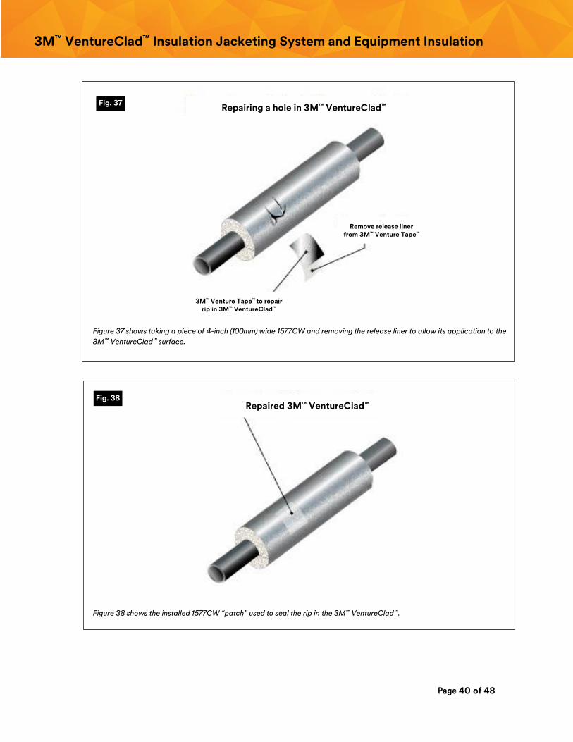
Figure 37 shows taking a piece of 4-inch (100mm) wide 1577CW and removing the release liner to allow its application to the
3M™ VentureClad™ surface.
Figure 38 shows the installed 1577CW “patch” used to seal the rip in the 3M™ VentureClad™.
Fig. 37
Fig. 38
3M™ Venture Tape™ to repair rip in 3M™ VentureClad™
Remove release liner from 3M™ Venture Tape™
Repairing a hole in 3M™ VentureClad™
Repaired 3M™ VentureClad™
Page 41 of 48
3M™ VentureClad™ Insulation Jacketing System and Equipment Insulation
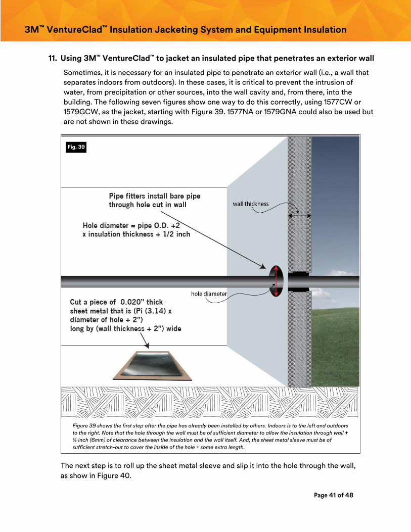
11. Using 3M™ VentureClad™ to jacket an insulated pipe that penetrates an exterior wall
Sometimes, it is necessary for an insulated pipe to penetrate an exterior wall (i.e., a wall that
separates indoors from outdoors). In these cases, it is critical to prevent the intrusion of
water, from precipitation or other sources, into the wall cavity and, from there, into the
building. The following seven figures show one way to do this correctly, using 1577CW or
1579GCW, as the jacket, starting with Figure 39. 1577NA or 1579GNA could also be used but
are not shown in these drawings.
Figure 39 shows the first step after the pipe has already been installed by others. Indoors is to the left and outdoors
to the right. Note that the hole through the wall must be of sufficient diameter to allow the insulation through wall +
¼ inch (6mm) of clearance between the insulation and the wall itself. And, the sheet metal sleeve must be of
sufficient stretch-out to cover the inside of the hole + some extra length.
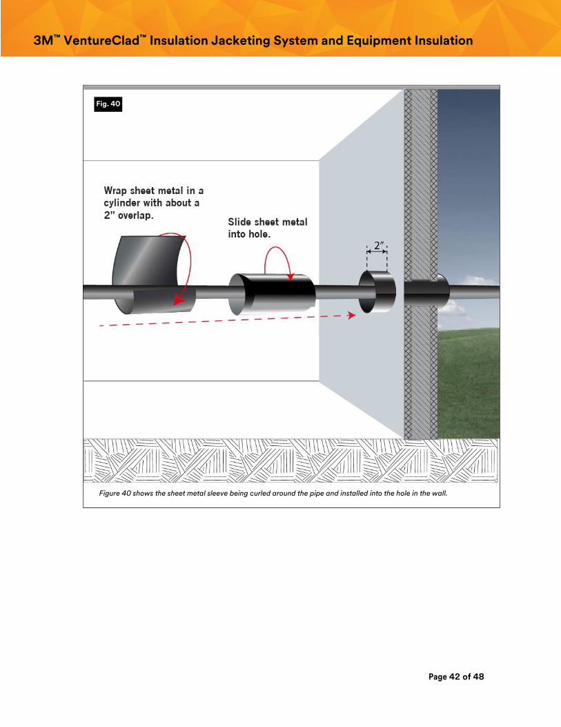
The next step is to roll up the sheet metal sleeve and slip it into the hole through the wall,
as show in Figure 40.
Fig. 39
Page 42 of 48
3M™ VentureClad™ Insulation Jacketing System and Equipment Insulation
Figure 40 shows the sheet metal sleeve being curled around the pipe and installed into the hole in the wall.
Fig. 40
Page 43 of 48
3M™ VentureClad™ Insulation Jacketing System and Equipment Insulation
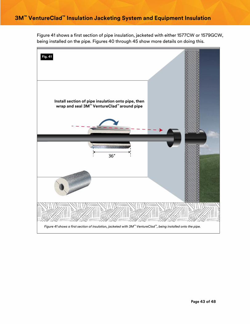
Figure 41 shows a first section of pipe insulation, jacketed with either 1577CW or 1579GCW,
being installed on the pipe. Figures 40 through 45 show more details on doing this.
Figure 41 shows a first section of insulation, jacketed with 3M™ VentureClad™, being installed onto the pipe.
Fig. 41
Install section of pipe insulation onto pipe, then wrap and seal 3M™ VentureClad™ around pipe
Page 44 of 48
3M™ VentureClad™ Insulation Jacketing System and Equipment Insulation
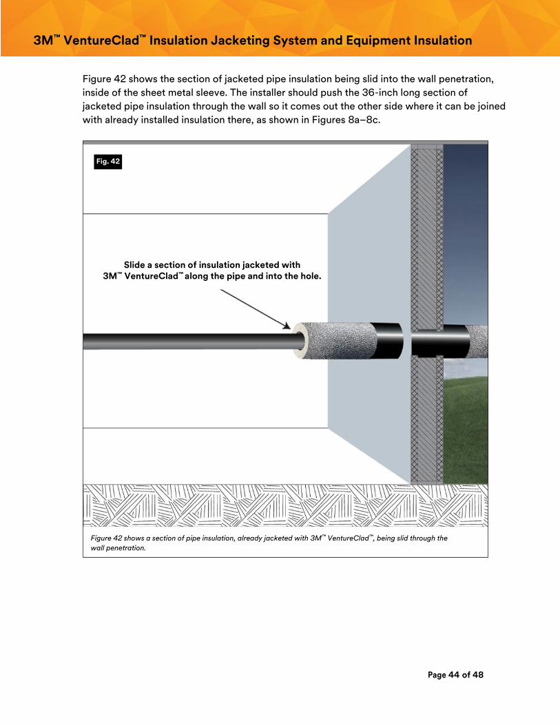
Figure 42 shows the section of jacketed pipe insulation being slid into the wall penetration,
inside of the sheet metal sleeve. The installer should push the 36-inch long section of
jacketed pipe insulation through the wall so it comes out the other side where it can be joined
with already installed insulation there, as shown in Figures 8a–8c.
Figure 42 shows a section of pipe insulation, already jacketed with 3M™ VentureClad™, being slid through the
wall penetration.
Fig. 42
Slide a section of insulation jacketed with 3M™ VentureClad™ along the pipe and into the hole.
Page 45 of 48
3M™ VentureClad™ Insulation Jacketing System and Equipment Insulation
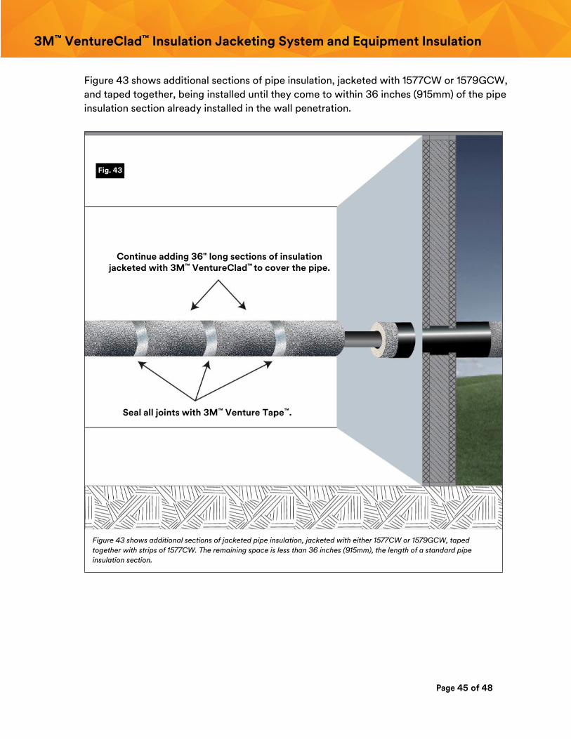
Figure 43 shows additional sections of pipe insulation, jacketed with 1577CW or 1579GCW,
and taped together, being installed until they come to within 36 inches (915mm) of the pipe
insulation section already installed in the wall penetration.
Figure 43 shows additional sections of jacketed pipe insulation, jacketed with either 1577CW or 1579GCW, taped
together with strips of 1577CW. The remaining space is less than 36 inches (915mm), the length of a standard pipe
insulation section.
Fig. 43
Continue adding 36" long sections of insulation jacketed with 3M™ VentureClad™ to cover the pipe.
Seal all joints with 3M™ Venture Tape™.
Page 46 of 48
3M™ VentureClad™ Insulation Jacketing System and Equipment Insulation
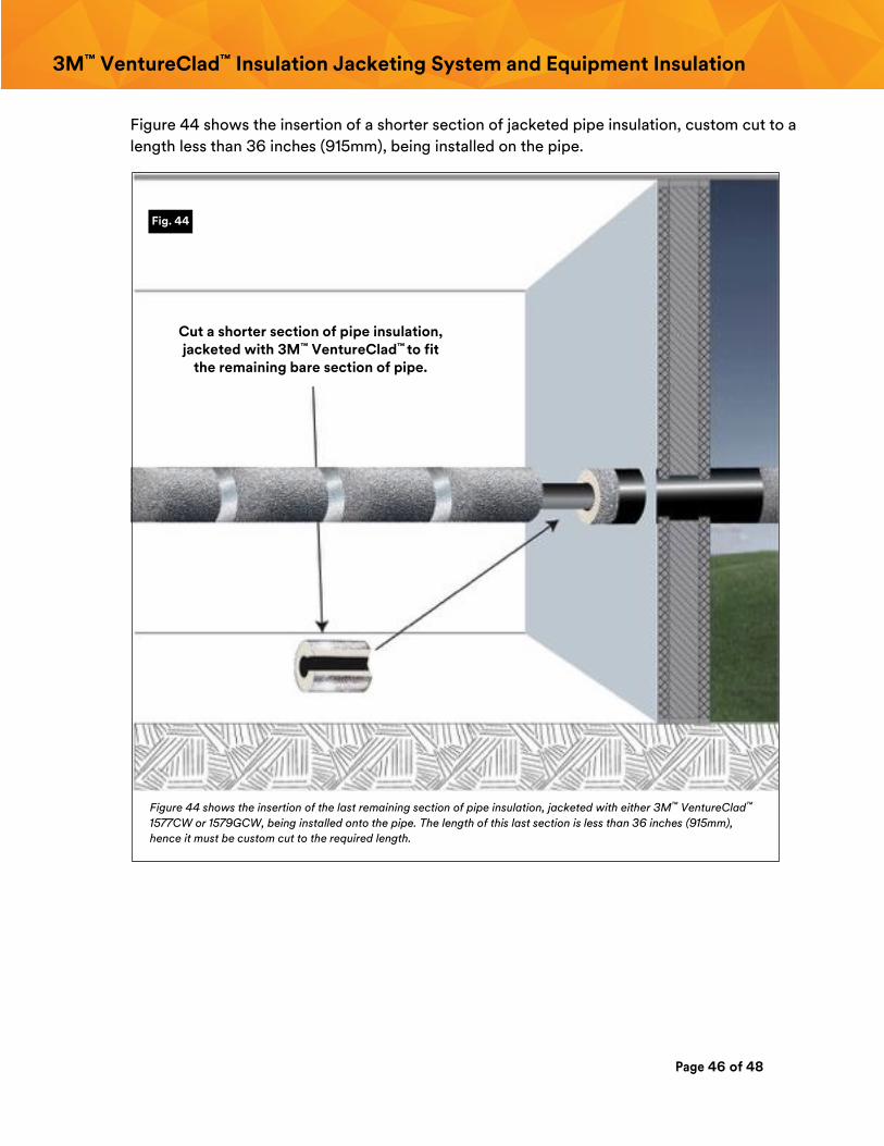
Figure 44 shows the insertion of a shorter section of jacketed pipe insulation, custom cut to a
length less than 36 inches (915mm), being installed on the pipe.
Figure 44 shows the insertion of the last remaining section of pipe insulation, jacketed with either 3M™ VentureClad™
1577CW or 1579GCW, being installed onto the pipe. The length of this last section is less than 36 inches (915mm),
hence it must be custom cut to the required length.
Fig. 44
Cut a shorter section of pipe insulation, jacketed with 3M™ VentureClad™ to fit
the remaining bare section of pipe.
Page 47 of 48
3M™ VentureClad™ Insulation Jacketing System and Equipment Insulation
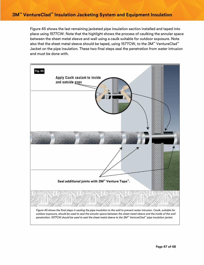
Figure 45 shows the last remaining jacketed pipe insulation section installed and taped into
place using 1577CW. Note that the highlight shows the process of caulking the annular space
between the sheet metal sleeve and wall using a caulk suitable for outdoor exposure. Note
also that the sheet metal sleeve should be taped, using 1577CW, to the 3M™ VentureClad™
Jacket on the pipe insulation. These two final steps seal the penetration from water intrusion
and must be done with.
Figure 45 shows the final steps in sealing the pipe insulation to the wall to prevent water intrusion. Caulk, suitable for
outdoor exposure, should be used to seal the annular space between the sheet metal sleeve and the inside of the wall
penetration. 1577CW should be used to seal the sheet metal sleeve to the 3M™ VentureClad™ pipe insulation jacket.
Fig. 45
Seal additional joints with 3M™ Venture Tape™.
Page 48 of 48
Technical Information The technical information, recommendations and other statements contained in this document are based upon tests or experience
that 3M believes are reliable, but the accuracy or completeness of such information is not guaranteed.
Product Use
Many factors beyond 3M’s control and uniquely within user’s knowledge and control can affect the use and performance of a 3M
product in a particular application. As a result, customer is solely responsible for evaluating the product and determining whether it is
appropriate and suitable for customer’s application, including conducting a workplace hazard assessment and reviewing all applicable
regulations and standards (e.g., OSHA, ANSI, etc.). Failure to properly evaluate, select, and use a 3M product and appropriate safety
products, or to meet all applicable safety regulations, may result in injury, sickness, death, and/or harm to property.
Warranty, Limited Remedy, and Disclaimer
Unless a different warranty is specifically stated on the applicable 3M product packaging or product literature (in which case such
warranty governs), 3M warrants that each 3M product meets the applicable 3M product specification at the time 3M ships the
product. 3M MAKES NO OTHER WARRANTIES OR CONDITIONS, EXPRESS OR IMPLIED, INCLUDING, BUT NOT LIMITED TO, ANY
IMPLIED WARRANTY OR CONDITION OF MERCHANTABILITY, FITNESS FOR A PARTICULAR PURPOSE, OR ARISING OUT OF A
COURSE OF DEALING, CUSTOM, OR USAGE OF TRADE. If a 3M product does not conform to this warranty, then the sole and
exclusive remedy is, at 3M’s option, replacement of the 3M product or refund of the purchase price.
Limitation of Liability
Except for the limited remedy stated above, and except to the extent prohibited by law, 3M will not be liable for any loss or damage
arising from or related to the 3M product, whether direct, indirect, special, incidental, or consequential (including, but not limited to,
lost profits or business opportunity), regardless of the legal or equitable theory asserted, including, but not limited to, warranty,
contract, negligence, or strict liability.
This Industrial Adhesives and Tapes Division product was manufactured under a 3M quality system registered to ISO9001 standards.
ISO 9001
Industrial Adhesives and Tapes Division 3M Center, Building 225-3S-06 St. Paul, MN 55144-1000
Phone 800-362-3550
Fax 877-369-2923 Web 3M.com/Construction
3M, VentureClad and Venture Tape are trademarks of 3M Company.
Please recycle. Printed in USA © 3M 2017. All rights reserved.


![1 Steel Buildings Recommended Installation Guide Frame First Web[1]](https://img.pdfslide.net/doc/110x75/55725c20497959da6be89df9/1-steel-buildings-recommended-installation-guide-frame-first-web1.jpg)


