Embed Size (px)
Citation preview
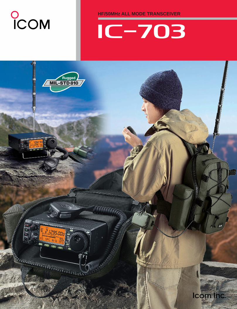
HF/50MHz ALL MODE TRANSCEIVER
i703
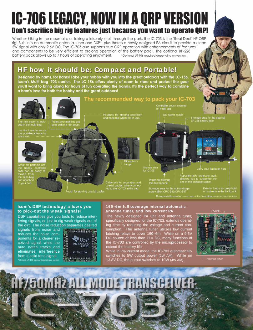
HF how it should be: Compact and Portable!
The rain cover is inclu-ded in the multi-bag.
Pouch for stowingthe microphone
Stowage area for the optional sep-arate cable, OPC-581/OPC-587
Repositionable protection pad, allowing you to customize the size of the stowage space
Carry your log book here
Exterior loops securely hold an antenna to the backpack
Stowage area for the optional BP-228 battery pack
DC power cables
Controller pouch secured on multi-bag
Pouches for stowing controller and hand mic when not in use.
Great for portable use, the handy controller case can be easily re-moved from the multi-bag and attached to your belt.
Use the loops to secure your portable antenna for safe travel.
Protect your multi-bag and gear with the rain cover.
The recommended way to pack your IC-703
Cable exit for separation and coaxial cables, when connec-ted to the IC-703 in the bag.
Pouch for stowing coaxial cables
Microphonehanger
Storage area for IC-703
HF how it should be: Compact and Portable!
Icom's DSP technology allows you to pick-out the weak signals!DSP capabilities give you tools to reduce inter-fering signals, or just to dig weak signals out of the dirt. The noise reduction separates desired signals from noise and reduces the noise com-ponents for a clearer re-ceived signal, while the auto notch tracks and eliminates interference from a solid tone signal. * Optional UT-106 required depending on version.
160–6m full coverage internal automatic antenna tuner, and low current PAThe newly designed PA unit and antenna tuner, specifically designed for the IC-703, extends operat-ing time by reducing the voltage and current con-sumption. The antenna tuner utilizes low current latching relays to cover 160–6m. While on a 9.6V DC source or less than 11V DC, many functions of the IC-703 are controlled by the microprocessor to extend the battery life. While in low current mode, the IC-703 automatically switches to 5W output power (2W AM). While on 13.8V DC, the output switches to 10W (4W AM). Antenna tuner
PA unit
During portable operation, make sure not to harm other people or environments.
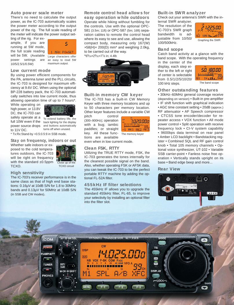
Auto power scale meterThere’s no need to calculate the outputpower, as the IC-703 automatically scalesthe power meter according to the outputpower of the rig. The full scale reading ofthe meter will indicate the power output set-ting of the rig. For ex-ample, if you arerunning at 5W mode,the full scale readingwill be 5W. (Availablepower settings are10/5/2.5/1/0.5W)
Low current modeBy using power efficient components forthe PA, antenna tuner and the PLL circuits,the IC-703 is designed for maximum effi-ciency at 9.6V DC. When using the optionalBP-228 battery pack, the IC-703 automati-cally switches into low current mode, thusallowing operation time of up to 7 hours*.While operating onhigh power, or 13.8VDC, the IC-703 cansafely operate at afull 10W even if thepower source dropsto 11V DC.* Tx:Rx:Stand-by =0.5:0.5:9 in SSB mode.
Stay on frequency, indoors or outWhether safe indoors or ex-posed to the cold tempera-tures outdoors, the IC-703will be right on frequencywith the standard ±0.5ppmTCXO.
High sensitivityThe IC-703’s receiver performance is in thesame class as that of high end base sta-tions: 0.16µV at 10dB S/N for 1.8 to 30MHzbands and 0.13µV for 50MHz at 10dB S/N(in SSB and CW modes).
Remote control head allows foreasy operation while outdoorsOperate while hiking without fumbling forthe controls. Use with the optional OPC-581 (3.5m; 11ft) or OPC-587 (5m; 16ft) sepa-ration cables to remote the control headwhere its easy to see and use, allowing thecompact body, measuring only 167(W)×58(H)× 200(D) mm* and weighing 2.0kg,to be carried out of the way.*69⁄16×29⁄32×77⁄8 in; 4.4lb
Built-in memory CW keyerThe IC-703 has a built-in CW MemoryKeyer with three memory locations and upto 50 characters per memory location.Other keyer features include a variable CWpitch control(300–900Hz); operationwith a bug; iambicpaddles; or straightkey. All these func-tions are availableeven when in low current mode.
Clean FSK, RTTYUtilizing the TRUE RTTY mode, FSK, theIC-703 generates the tones internally forthe cleanest possible signal on the band.Also, whether operating FSK or AFSK data,you can tweak the IC-703 to be the perfectportable RTTY machine by adding the op-tional FL-52A filter.
455kHz IF filter selectionsThe 455kHz IF allows you to upgrade thestandard 455kHz filter, FL-65, to improveyour selectivity by installing an optional filterinto the filter slot.
Built-in SWR analyzerCheck out your antenna’s SWR with the in-ternal SWR analyzer.The resolution of theIC-703’s SWR graphbandwidth is ad-justable from 10/50/100/500kHz.
Band scopeCatch band activity at a glance with theband scope. With the operating frequencyin the center of thedisplay, each step ei-ther to the left or rightof center is selectablefrom 0.5/1/2/5/10/20/100 kHz steps.
Other outstanding features• 30kHz–60MHz general coverage receive(depending on version) • Built-in pre-amplifier• IF shift function with graphical indication • AGC time constant setting • 20dB (approx.)RF attenuator • AF Speech compressor • CTCSS tone encoder/decoder for re-peater access • VOX function • All modepower control • Split operation with receivefrequency lock • CI-V system capability • 9600bps data terminal on rear panel • Amber LCD backlight • Bandstacking reg-ister • Combined SQL and RF gain controlknob • Total 105 memory channels • Op-tional voice synthesizer, UT-102 • VariableSSB carrier-point • Fanless noise free op-eration • Vertically stands upright on itsbase • Band edge beep and more...
Large characters offeran easy to read 5Wmaximum output.
To extend battery life, theback lighting for the displayand buttons automaticallyturns off when unused.
Close up of theTCXO circuit
The memory keyer
Graphing the SWR
The band scope
Rear View
• Frequency coverage* :Receive 0.030– 60.000MHz Transmit 1.800– 1.999MHz 3.500– 3.999MHz
5.000– 5.499MHz 7.000– 7.300MHz10.100– 10.150MHz 14.000– 14.350MHz18.068– 18.168MHz 21.000– 21.450MHz24.890– 24.990MHz 28.000– 29.700MHz50.000– 54.000MHz
* Frequency range varies and some frequency ranges are not guar-anteed depending on version. 5MHz and 50MHz bands availabledepending on version.
• Mode : USB, LSB, CW, RTTY, AM, FM• No. of channels : 105 (99 regular, 6 scan edges)• Antenna impedance : 50Ω (SO-239)• Power supply requirement : 9–15.8V DC• Operating temp. range : –10°C to +60°C; +14°F to +140°F• Frequency stability : Less than ±0.5ppm (+0°C to +50°C)
Less than ±2.5ppm (–10°C to +60°C)• Output power and current drain :
• Dimensions (W×H×D) : 167 × 58 × 200 mm; (projections not included) 69⁄16 × 29⁄32 × 77⁄8 in
• Weight : 2.0kg; 4.4lb• CI-V connector : 2-conductor 3.5 (d) mm (1⁄8˝)
• Modulation system :SSB Balanced modulationAM Low level modulationFM Variable reactance modulation
• Spurious emissions : Less than –50dB (Below 30MHz)Less than –60dB (Above 50MHz)
• Carrier suppression : More than 40dB• Unwanted sideband : More than 50dB
suppression• Microphone connector : 8-pin modular jack (600Ω)• CW KEY connector : 3-conductor 6.35 (d) mm (1⁄4˝)
• Receive system : Double conversion superheterodyne• Intermediate frequency : 1st/2nd 64.455/0.455MHz
• Sensitivity (typical) :• Squelch sensitivity : SSB 5.6µV typ.
(threshold; pre-amp on) FM 0.32µV typ.• Selectivity :
SSB, CW (2.4kHz) More than 2.4kHz/–6dB
Less than 4.0kHz/–60dBAM/FM-N (6kHz) More than 9.0kHz/–6dB
Less than 20kHz/–50dBFM (15kHz) More than 15kHz/–6dB
Less than 30kHz/–50dB• Spurious and image rejection ratio:
HF bands More than 70dB50MHz More than 65dB (except IF point)
• Audio output power : More than 1.0W (at 13.8V DC)(8Ω load, 10% distortion) More than 0.5W (at 9.6V DC)
• RIT variable range : ±9.99kHz• PHONES connector : 3-conductor 3.5 (d) mm (1⁄8˝)• EXT SP connector : 2-conductor 3.5 (d) mm (1⁄8˝)/8Ω
1-1-32, Kamiminami, Hirano-ku, Osaka 547-0003, Japan Phone: +81 (06) 6793 5302 Fax: +81 (06) 6793 0013 Count on us!URL: http://www.icom.co.jp/world/index.html
Printed in Japan
2380 116th Avenue NE, Bellevue, WA 98004, U.S.A.Phone : +1 (425) 454-8155Fax : +1 (425) 454-1509E-mail : [email protected] : http://www.icomamerica.com
Communication EquipmentHimmelgeister Str. 100, D-40225 Düsseldorf, GermanyPhone : +49 (0211) 346047Fax : +49 (0211) 333639E-mail : [email protected] : http://www.icomeurope.com
A.B.N. 88 006 092 575Unit 1 / 103 Garden Road,Clayton VIC 3168 AustraliaPhone : +61 (03) 9549 7500Fax : +61 (03) 9549 7505 E-mail : [email protected] : http://www.icom.net.au
Unit 9, Sea St., Herne Bay, Kent, CT6 8LD, U.K.Phone : +44 (01227) 741741Fax : +44 (01227) 741742E-mail : [email protected] : http://www.icomuk.co.uk
Zac de la Plaine, 1, Rue Brindejonc des Moulinais BP 5804, 31505 Toulouse Cedex, FrancePhone : +33 (5) 61 36 03 03Fax : +33 (5) 61 36 03 00E-mail : [email protected] : http://www.icom-france.com
Ctra. Rubi, No. 88 "Edificio Can Castanyer"08190, Sant Cugat del Valles, Barcelona, SpainPhone : +34 (93) 590 26 70Fax : +34 (93) 589 04 46E-mail : [email protected] : http://www.icomspain.com
146A Harris Road, East Tamaki, Auckland, New ZealandPhone : +64 (09) 274 4062Fax : +64 (09) 274 4708E-mail : [email protected] : http://www.icom.co.nz
Glenwood Centre #150-6165 Highway 17, Delta, B.C., V4K 5B8, CanadaPhone : +1 (604) 952-4266Fax : +1 (604) 952-0090E-mail : [email protected] : http://www.icomcanada.com
Your local distributor/dealer:
JP98/14190QA TW03/00288EM
Icom Inc. (Japan), is an ISO 9001 and ISO 14001 certification acquired company.
6F No. 68, Sec. 1 Cheng-Teh Road, Taipei, Taiwan, R.O.C.Phone : +886 (02) 2559 1899Fax : +886 (02) 2559 1874E-mail : [email protected] : http://www.asia-icom.com
10C07, Long Silver Mansion, No.88, Yong DingRoad, Haidian District, Beijing, 100039, ChinaPhone : +86 (010) 5889 5391/5392/5393Fax : +86 (010) 5889 5395E-mail : [email protected] : http://www.bjicom.com
Sopot, 3 maja 54, PolandPhone : +48 (58) 550 7135Fax : +48 (58) 551 0484E-mail : [email protected] : http://www.icompolska.com.pl
HF/50MHz ALL MODE TRANSCEIVER
GENERAL
SPECIFICATIONSTRANSMITTER
All stated specifications are subject to change without notice orobligation.
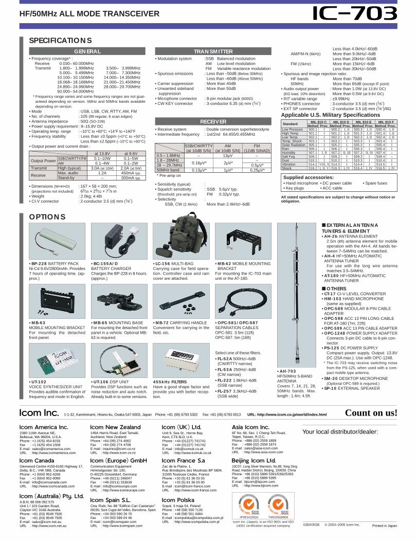
OPTIONS
RECEIVER
Supplied accessories:• Hand microphone • DC power cable • Spare fuses• Key plugs • ACC cable
• MB-63MOBILE MOUNTING BRACKETFor mounting the detachedfront panel.
• MB-72 CARRYING HANDLEConvenient for carrying in thefield, etc.
• OPC-581/OPC-587SEPARATION CABLESOPC-581: 3.5m (11ft)OPC-587: 5m (16ft)
455kHz FILTERSHave a good shape factor andprovide you with better recep-tion.
• UT-106 DSP UNITProvides DSP functions such asnoise reduction and auto notch.Already built-in to some versions.
• UT-102VOICE SYNTHESIZER UNITProvides audible confirmation offrequency and mode in English.
• AH-703HF/50MHz 5-BANDANTENNACovers 7, 14, 21, 28,50MHz bands. Max.length ; 1.4m; 4.5ft.
• BP-228 BATTERY PACK Ni-Cd 9.6V/2800mAh. Provides7 hours of operating time. (ap-prox.)
• BC-155A/DBATTERY CHARGERCharges the BP-228 in 8 hours.(approx.)
• LC-156 MULTI-BAGCarrying case for field opera-tion. Controller case and raincover are attached.
0.5 – 1.8MHz1.8 – 28MHz28 – 29.7MHz50MHz band* Pre-amp on
SSB/CW/RTTY(at 10dB S/N)
–
0.16µV*
0.13µV*
AM(at 10dB S/N)
13µV
2µV*
1µV*
FM(12dB SINAD)
––
0.5µV*0.25µV*
Output PowerSSB/CW/RTTY/FMAM
Transmit High (typical)
ReceiveMax. audioStand-by
at 13.8V0.1–10W0.1–4W
3.0A (at 10W)1.2A
–
at 9.6V0.1–5W0.1–2W
2.0A (at 5W)450mA typ.300mA typ.
• MB-62 MOBILE MOUNTINGBRACKET
For mounting the IC-703 mainunit or the AT-180.
• MB-65 MOUNTING BASE For mounting the detached frontpanel in a vehicle. Optional MB-63 is required.
Select one of these filters.• FL-52A 500Hz/–6dB
(CW/RTTY narrow)• FL-53A 250Hz/–6dB
(CW narrow)• FL-222 1.8kHz/–6dB
(SSB narrow)• FL-257 3.3kHz/–6dB
(SSB wide)
Applicable U.S. Military Specifications
Standard MIL 810 C MIL 810 D MIL 810 E MIL 810 FMethod Proc. Method Proc. Method Proc. Method Proc.
Low Pressure 500.1 I 500.2 I, II 500.3 I, II 500.4 I, IIHigh Temp. 501.1 I 501.2 I, II 501.3 I, II 501.4 I, IILow Temp. 502.1 I 502.2 I, II 502.3 I, II 502.4 I, IITemp. Shock 503.1 I 503.2 I 503.3 I 503.4 ISolar Radiation 505.1 I 505.2 I 505.3 I 505.4 IRain 506.1 I 506.2 I 506.3 I 506.4 IHumidity 507.1 I, II 507.2 II, III 507.3 II, III 507.4 –Salt Fog 509.1 I 509.2 I 509.3 I 509.4 –Dust 510.1 I 510.2 I 510.3 I 510.4 IVibration 514.2 VIII, X 514.3 I 514.4 I 514.5 I Shock 516.2 I, II, V 516.3 I, IV 516.4 I, IV 516.5 I, IV
EXTERNAL ANTENNATUNERS & ELEMENT• AH-2b ANTENNA ELEMENT
2.5m (8ft) antenna element for mobileoperation with the AH-4. All bands be-tween 7–54MHz can be matched.
• AH-4 HF+50MHz AUTOMATIC ANTENNA TUNER
For use with the long wire antennamatches 3.5–54MHz.
• AT-180 HF+50MHz AUTOMATIC ANTENNA TUNER
OTHERS• CT-17 CI-V LEVEL CONVERTER• HM-103 HAND MICROPHONE
(same as supplied)• OPC-589 MODULAR 8-PIN CABLE
ADAPTER• OPC-598 ACC 13 PIN LONG CABLE
FOR AT-180 (7m; 22ft)• OPC-599 ACC 13 PIN CABLE ADAPTER• OPC-1248 POWER SUPPLY ADAPTER
Connects 3-pin DC cable to 6-pin con-nector.
• PS-125 DC POWER SUPPLYCompact power supply. Output: 13.8VDC (25A max.). Use with OPC-1248.
* The IC-703 may receive switching noisefrom the PS-125, when used with a com-pact mobile type antenna.
• SM-20 DESKTOP MICROPHONE (Optional OPC-589 is required.)
• SP-10 EXTERNAL SPEAKER
03EK003E © 2003–2005 Icom Inc.